WO2024204231A1 - 快適性確認用人体ダミー - Google Patents
快適性確認用人体ダミー Download PDFInfo
- Publication number
- WO2024204231A1 WO2024204231A1 PCT/JP2024/012011 JP2024012011W WO2024204231A1 WO 2024204231 A1 WO2024204231 A1 WO 2024204231A1 JP 2024012011 W JP2024012011 W JP 2024012011W WO 2024204231 A1 WO2024204231 A1 WO 2024204231A1
- Authority
- WO
- WIPO (PCT)
- Prior art keywords
- dummy
- comfort
- resin
- skeletal
- resin material
- Prior art date
- Legal status (The legal status is an assumption and is not a legal conclusion. Google has not performed a legal analysis and makes no representation as to the accuracy of the status listed.)
- Ceased
Links
Images


Classifications
-
- G—PHYSICS
- G01—MEASURING; TESTING
- G01M—TESTING STATIC OR DYNAMIC BALANCE OF MACHINES OR STRUCTURES; TESTING OF STRUCTURES OR APPARATUS, NOT OTHERWISE PROVIDED FOR
- G01M17/00—Testing of vehicles
- G01M17/007—Wheeled or endless-tracked vehicles
- G01M17/0078—Shock-testing of vehicles
-
- G—PHYSICS
- G01—MEASURING; TESTING
- G01M—TESTING STATIC OR DYNAMIC BALANCE OF MACHINES OR STRUCTURES; TESTING OF STRUCTURES OR APPARATUS, NOT OTHERWISE PROVIDED FOR
- G01M17/00—Testing of vehicles
- G01M17/007—Wheeled or endless-tracked vehicles
-
- G—PHYSICS
- G01—MEASURING; TESTING
- G01M—TESTING STATIC OR DYNAMIC BALANCE OF MACHINES OR STRUCTURES; TESTING OF STRUCTURES OR APPARATUS, NOT OTHERWISE PROVIDED FOR
- G01M7/00—Vibration-testing of structures; Shock-testing of structures
- G01M7/08—Shock-testing
-
- G—PHYSICS
- G09—EDUCATION; CRYPTOGRAPHY; DISPLAY; ADVERTISING; SEALS
- G09B—EDUCATIONAL OR DEMONSTRATION APPLIANCES; APPLIANCES FOR TEACHING, OR COMMUNICATING WITH, THE BLIND, DEAF OR MUTE; MODELS; PLANETARIA; GLOBES; MAPS; DIAGRAMS
- G09B25/00—Models for purposes not provided for in G09B23/00, e.g. full-sized devices for demonstration purposes
-
- G—PHYSICS
- G09—EDUCATION; CRYPTOGRAPHY; DISPLAY; ADVERTISING; SEALS
- G09B—EDUCATIONAL OR DEMONSTRATION APPLIANCES; APPLIANCES FOR TEACHING, OR COMMUNICATING WITH, THE BLIND, DEAF OR MUTE; MODELS; PLANETARIA; GLOBES; MAPS; DIAGRAMS
- G09B9/00—Simulators for teaching or training purposes
Definitions
- the present invention relates to a human dummy for comfort testing that has a lightweight skeletal structure that closely resembles the bones of the human body.
- crash test anthropomorphs human dummies
- crash safety performance tests have been conducted by having anthropomorphs sit in automobiles in the same way as humans, and the data obtained from these tests has been analyzed and used to improve the crash safety performance of automobiles.
- a known example of such an anthropomorphic dummy is one that has a skeletal structure with properties similar to those of the human bones (see, for example, Patent Document 1).
- This anthropomorphic dummy has a structure that exhibits physical properties similar to those of the human body and is formed to have an appropriate bone weight, so it is particularly configured to be able to accurately reproduce the causes of injuries such as fractures suffered by humans, as well as damage to the skeletal structure.
- anthropomorphic dummies have also been used in confirmation tests to check the livability and comfort of the interior space of automobiles.
- confirmation tests since the anthropomorphic dummy is a heavy object with the same bone weight or total weight as a human body, multiple test executors carry the anthropomorphic dummy and have it seated inside the vehicle and set up in the correct position.
- the present invention aims to improve on the above-mentioned conventional technology and provide a highly portable human dummy for comfort testing that has a lightweight skeletal part or total weight that is similar to the bones of the human body.
- the comfort confirmation human dummy of the present invention comprises a skeletal portion molded from a resin material, a fleshy portion surrounding the outer periphery of the skeletal portion and a skin portion disposed on the surface side of the fleshy portion, the fleshy portion being formed from a material different from the resin material, the skeletal portion being molded from different resin materials depending on the part of the bone, and having a bone weight of 10% to 60% of the bone weight of the skeletal portion of an internationally standardized human dummy for crash safety performance testing based on human body data.
- the skeletal portion includes an upper limb portion excluding the upper limb girdle and a lower limb portion excluding the femur and knee, which are molded from a first resin material, and a skull, cervical vertebrae, spine, the upper limb girdle, pelvis, the femur, and the knee, which are molded from a second resin material.
- the first resin material is a thermoplastic resin having a heat resistance temperature of 200°C or higher.
- the first resin material is carbon fiber resin or PPS resin.
- the second resin material is ABS resin or PLA resin.
- the skeletal portion is formed by a three-dimensional modeling device.
- the head including the skull, is connected to at least one of the cervical vertebrae and the upper limb girdle so that the head can be turned left or right by a predetermined angle from a state in which the head faces forward.
- a human dummy for confirming comfort which comprises a skeleton molded from a resin material, a fleshy part surrounding the outer periphery of the skeleton, and a skin part arranged on the surface side of the fleshy part, both of which are formed from a material different from the resin material, and the skeleton is molded from different resin materials depending on the part of the bone, and the total weight of the skeleton, the fleshy part, and the skin part is between 10% and 60% of the total weight of a human dummy for crash safety performance testing that is internationally standardized based on human body data.
- the present invention provides a highly portable human dummy for comfort testing that has a lightweight skeletal structure or total weight that is similar to the bones of the human body.
- FIG. 1 is a front view showing, in outline, the overall configuration of a comfort confirmation dummy according to a first embodiment of the present invention, with the skeleton emphasized.
- 2 is a cross-sectional view taken along line AA' in FIG. 11 is a diagram for illustrating the schematic configuration of the skull of a comfort confirmation dummy according to a second embodiment of the present invention.
- FIG. 13 is a diagram for illustrating the schematic configuration of the spine of the comfort confirmation dummy.
- FIG. 13 is a diagram for illustrating the schematic configuration of a femur part of the comfort confirmation dummy.
- FIG. 13 is a diagram for illustrating the schematic configuration of the knees of the comfort confirmation dummy.
- the human body data may be, for example, data on a specific individual, or may be data obtained from at least one of the standard body types of the human body, such as the average male or female body within a specified age range, the average young male or female body, the average middle-aged male or female body, and the average elderly male or female body.
- standard body types of the human body include those specified in the above-mentioned standard (49 CFR Part 572).
- the skeleton 2 is molded, for example, from different resin materials depending on the part of the bone.
- the skeleton 2 is also molded to have a bone weight of 10% to 60%, and preferably 10% to 51%, of the bone weight of the skeleton of an internationally standardized human body dummy for crash safety performance testing based on human body data (for example, a human body dummy such as a Hybrid III 50th percentile male (50% standard male)).
- a human body dummy such as a Hybrid III 50th percentile male (50% standard male)
- the Hybrid III 5th percentile female crash safety performance testing dummy will be referred to as the "reference dummy”.
- the skeletal section 2 includes, for example, an upper limb section 101, a lower limb section 102, a skull 91, a cervical vertebrae 14, a spine 90 including lumbar vertebrae, a pelvis 80, and a thorax 92.
- the upper limb section 101 includes, for example, an upper limb girdle 11 having a scapula 11a and a clavicle 11b, a humerus 5, an ulna 6, a radius 7, a carpal radius 8a, and a hand bone 8b.
- the lower limb section 102 includes, for example, a femur 9, a tibia 12a, a fibula 12b, a knee 61, a talus 13a, and a foot bone 13b.
- the skeletal part 2 thus constructed has an upper limb part 101 excluding the upper limb girdle 11 (hereinafter referred to as the "upper limb part”), and a lower limb part 102 excluding the femur 9 and knee 61 (hereinafter referred to as the "lower limb part”), which are molded from a first resin material, a thermoplastic resin having a heat resistance temperature of 200°C or higher.
- the skeletal part 2 has a skull 91, cervical vertebrae 14, spine 90, upper limb girdle 11, pelvis 80, femur 9, knee 61, and thorax 92 (hereinafter collectively referred to as "other parts 103”) molded from a second resin material different from the first resin material.
- the thorax 92 is formed in the shape of a curved plate with a cavity inside that functions as a substitute bone, but it may be formed in a shape that corresponds to the ribs of a normal human body. If the thorax 92 is made up of such substitute bones, it is possible to reduce the number of parts that make up the skeletal section 2 and simplify the manufacturing process, compared to a thorax made up of multiple ribs.
- the first resin material may be, for example, carbon fiber resin (carbon resin) or a lightweight resin having the same performance (such as PPS resin (polyphenylene sulfide resin)).
- the second resin material may be, for example, ABS resin (acrylonitrile butadiene styrene copolymer synthetic resin) or PLA resin (polylactic acid resin), and PA12 (polyamide 12) resin may also be used.
- the first resin material is described as being carbon resin
- the second resin material is described as being ABS resin, but this is not limited to this.
- the upper limbs 101 and lower limbs 102 of the skeleton 2 are shaped by a three-dimensional modeling device (3D printer) (not shown) that uses carbon resin as the resin filament.
- the upper limbs 101 and lower limbs 102 are then shaped by sintering in a molding oven (not shown) or the like.
- the other parts 103 are shaped by a 3D printer that uses ABS resin as the resin filament, and are shaped after a predetermined cooling period has passed.
- the skeletal portion 2 Since the skeletal portion 2 is molded as described above, it can be constructed to be extremely lightweight, with a bone weight of 10% to 51% of that of the skeletal portion of the reference dummy.
- An example of the bone weight of the skeletal portion 2 of the human dummy 1 relative to the bone weight of the skeletal portion of the reference dummy is as follows. For example, if the bone weight of the skull of the reference dummy is 3.73 kg, the bone weight of the skull 91 of the human dummy 1 is molded to be 1.86 kg. Furthermore, if the bone weight of the cervical vertebrae of the reference dummy is 0.91 kg, the bone weight of the cervical vertebrae 14 of the human dummy 1 is molded to be 0.455 kg.
- the bone weight of the spine of the reference dummy is 12.02 kg
- the bone weight of the spine 90 of the human dummy 1 is formed to be 6.0 kg.
- the bone weight of the pelvis 80 of the reference dummy is 13.25 kg
- the bone weight of the pelvis 80 of the human dummy 1 is formed to be 6.63 kg.
- the bone weight of one humerus of the reference dummy is 1.18 kg and the bone weight of one ulna and radius is 0.9 kg (total 2.08 kg)
- the bone weight of one humerus 5 of the human dummy 1 is formed to be 0.59 kg and the bone weight of one ulna 6 and radius 7 is formed to be 0.45 kg (total 1.04 kg).
- the weight of one femur of the reference dummy is 3.13 kg, then the weight of one femur 9 of the human dummy 1 is 1.565 kg. If the weight of one tibia and fibula of the reference dummy is 3.27 kg, then the weight of one tibia 12a and fibula 12b of the human dummy 1 is 1.635 kg. If the weight of one talus and foot bone of the reference dummy is 0.79 kg, then the weight of one talus 13a and foot bone 13b of the human dummy 1 is 0.395 kg.
- the bone weight of the reference dummy is 48.45 kg, and the total bone weight is set to 49.05 kg including the weight of other connecting parts (not shown), 0.6 kg.
- the bone weight of the anthropomorphic dummy 1 is 24.215 kg, and the total bone weight is set to 25.0 kg including the weight of connecting parts (0.785 kg).
- the bone weight of the skeletal part 2 of the anthropomorphic dummy 1 is approximately 50% (approximately 51% or less) of the bone weight of the skeletal part of the reference dummy.
- the bone weight of the skeletal part 2 of the anthropomorphic dummy 1 is approximately 10% of the bone weight of the skeletal part of the reference dummy
- the bone weight of the skeletal part 2 can be set to approximately 5 kg.
- the structure of each of the above bones is formed as a hollow structure, etc., to reduce the weight.
- the human dummy 1 of this embodiment has a skeletal part 2 similar to the bones of the human body, but is highly lightweight, making it very portable. This makes it possible to reduce the manpower required for transporting it inside the vehicle and setting it up, compared to conventional methods.
- the fleshy portion 3 of the human dummy 1 can be formed so as to surround and cover the outer periphery of the skeletal portion 2, and can be formed to reproduce, for example, a fleshy shape that matches the body type (fleshiness) of a human body, or a fleshy shape that matches the body type of a reference dummy.
- the fleshy portion 3 is formed from a material different from the first and second resin materials that make up the skeletal portion 2, such as urethane resin, but is not limited to this.
- the skin portion 4 is formed from polyvinyl chloride resin or urethane foam, and is arranged on the surface side of the fleshy portion 3 so as to surround the outer periphery of the fleshy portion 3.
- the skin portion 4 is formed to a thickness of, for example, about 10 mm, but it can be made thinner than this to realize a lighter anthropomorphic dummy 1, and the thickness can be changed appropriately to suit the part of the human body, and is not limited to this.
- the fleshy portion 3 and the skin portion 4 can be composed of fleshy portions and skin portions made of various known materials that are applicable to anthropomorphic dummies.
- the fleshy portion 3 and skin portion 4 constructed as described above, it can be used without any sense of incongruity with the reference dummy when taking photographs of the interior space of a vehicle. Furthermore, since the human dummy 1 constructed in this way has a lightweight skeletal portion 2 with properties similar to those of human bones, it can be used in place of a human body in various tests to obtain various data, can be useful in investigating the causes of crash tests and reproducing dangerous areas of the human body, and can be used to check the acoustic space inside the vehicle by placing an acoustic sensor near the ear.
- each part of the skeletal part 2, fleshy part 3 and skin part 4 of the human dummy 1 can be made to be lighter than the reference dummy, while being adapted to the age, sex, body type, etc. of the human body based on the human body data and the specifications of the reference dummy.
- the skeletal part 2 of the human dummy 1 can be configured to include multiple movable joints, just like the human body or the reference dummy.
- the multiple movable joints can move from this reference state within a predefined movable range at least one of the vertical operating angle, horizontal operating angle, and tilt operating angle that are individually determined at the connection points of the joints.
- the multiple movable joints of the skeleton 2 can be formed with a movable range that allows adduction, abduction, flexion, and extension similar to that of the movable joints of the human body, by using the above-mentioned operating angles, as an example.
- the skeleton 2 can be formed with each of the joints of a neck joint 10, a shoulder joint 20, an elbow joint 30, a radiocarpal joint 40, a hip joint 50, a knee joint 60, and a talocrural joint 70.
- the neck joint 10 can be configured to reproduce the range of motion of the cervical vertebrae 14, for example, and can be configured to include an atlanto-occipital joint, an atlantoaxial joint, and an intervertebral joint, similar to the skeleton of the human body. Note that each of these joints is formed so that it can move within the range described in the above-mentioned publicly known Patent Document 1 (Patent Publication No. 6934248), so a description thereof will be omitted here.
- the head (not shown) of the human dummy 1 including the skull 91 may be configured with a structure that allows the orientation of the head to be changed (the head to be moved left and right) by a predetermined angle (e.g., about 60°) to the left and right of the human dummy 1, as shown in Figure 2, from a state in which the skull 91 faces forward as shown by the solid lines in the figure, as shown by the dashed lines in the figure.
- a predetermined angle e.g., about 60°
- the head is connected to, for example, the cervical vertebrae 14 at a connection center 97 at the bottom surface of the skull 91, and is then supported by the trunk portion of the human dummy 1.
- the head is also supported by the trunk portion of the human dummy 1 by a number of head support rods 98 connected to, for example, the upper limb belt 11, which are connected to the skull 91 at a position radially away from the connection center 97 in the figure, on the bottom side of the skull 91.
- head support rods 98 There are two head support rods 98 in Figure 2, spaced 180° apart around the connection center 97, but the number is not limited to this.
- Each head support rod 98 is fitted into one of a number of arc-shaped grooves 96 formed in the bottom surface of the skull 91. These arc-shaped grooves 96 form grooves that extend in an arc, allowing the head support rods 98 to move relatively over a range of approximately 120° along the direction indicated by the arrow in the figure. If the head, including the skull 91, has a structure that allows it to move left and right in this way, the human body dummy 1 can also be used, for example, to test the left and right visibility of the occupant in relation to the installation of information presentation devices such as an instrument panel and a display device by having the occupant sit in the vehicle and then shaking the head left and right.
- information presentation devices such as an instrument panel and a display device
- the upper limbs 101 excluding the upper limb girdle 11 of the skeleton 2, and the lower limbs 102 excluding the femur 9 and knee 61 are molded from carbon resin or the like, and the remaining parts 103 are molded from ABS resin or the like, so that the skeleton can be molded to have a bone weight of 10% to 51% of the bone weight of the skeleton of the reference dummy.
- the configuration of the skeleton 2 is not limited to the one described above, and various configurations can be adopted, such as molding the cervical vertebrae 14, spine 90, and pelvis 80 as a single part.
- Fig. 3 is a diagram for generally explaining the configuration of the skull of the comfort check dummy according to the second embodiment of the present invention.
- Fig. 4 is a diagram for generally explaining the configuration of the spine of the comfort check dummy.
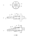
- Fig. 5 is a diagram for generally explaining the configuration of the femur of the comfort check dummy.
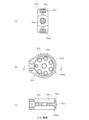
- Fig. 6 is a diagram for generally explaining the configuration of the knee of the comfort check dummy.
- explanations that overlap with the parts already explained will be omitted.
- the comfort check dummy according to the second embodiment has the same basic structure and materials as the comfort check dummy 1 according to the first embodiment, including the upper limbs 101, lower limbs 102, and other parts 103.
- the comfort check dummy according to the second embodiment differs from the first embodiment in that the total weight, including not only the skeletal part 2 but also the fleshy part 3 and skin part 4, is 10% to 60%, preferably 10% to 51%, of the total weight of the internationally standardized crash safety performance test dummy based on human body data.
- the total weight here refers to the weight that can be calculated including the weight of various associated parts such as bolts and nuts of each part and connecting members.
- the comfort confirmation dummy of the second embodiment has the following total weight.
- the total weight, including the skeletal portion 2, fleshy portion 3 and skin portion 4, of a comfort confirmation dummy of the same size (height, etc.) as the reference dummy A which corresponds to a Hybrid III 5th percentile female crash safety performance test dummy (U.S. CFR Part 572 Subpart O: Reference Dummy A) having a total weight of 50 kg ⁇ 5%, is 10% to 60%, preferably 10% to 51% (e.g., 4.75 kg to 31.5 kg, preferably 4.75 kg to 26.775 kg) of the total weight of the reference dummy A.
- the total weight, including the skeletal portion 2, fleshy portion 3 and skin portion 4, of a comfort confirmation dummy of the same size (height, etc.) as the reference dummy B which corresponds to a Hybrid III 95th percentile large adult male crash safety performance test dummy (US SAE Standard Large Male: Reference Dummy B) having a total weight of 100 kg ⁇ 5%, is 10% to 60%, preferably 10% to 51% (for example, 9.5 kg to 63 kg, preferably 9.5 kg to 53.55 kg) of the total weight of the reference dummy B.
- the total weight, including the skeletal portion 2, fleshy portion 3 and skin portion 4, of a comfort confirmation dummy of the same size (height, etc.) as the reference dummy C which corresponds to the 50th percentile dummy for crash safety performance testing of Hybrid III (CFR Part 572 Subpart E: Reference Dummy C) having a total weight of 75 kg ⁇ 5%, is 10% to 60%, preferably 10% to 51% (for example, 7.125 kg to 47.25 kg, preferably 7.125 kg to 40.1625 kg) of the total weight of the reference dummy C.
- the skeletal portion 2 of the comfort confirmation dummy is formed with a hollow structure and a cast structure including multiple cast holes in the areas corresponding to at least the skull 91A, spine 90A, femur 9A, and knee 61A.
- the comfort confirmation dummy corresponding to the reference dummy B will be described below as an example.
- the skull 91A is as shown in Figure 3.
- Figure 3(a) shows the front of the skull 91A
- Figure 3(b) shows the side of the skull 91A
- Figure 3(c) shows the cross section taken along line B-B' in Figure 3(b).
- the skull 91A of the comfort confirmation dummy has multiple cast holes 91a on the front, sides, lower jaw, top of the head, etc.
- the skull 91A has an internal hollow portion 91b that communicates with these multiple cast holes 91a.
- the skull 91A can be molded at approximately 2.03 kg, including the bones of the neck and other parts not shown.
- spine 90A At least a portion of the spine 90A (hereinafter referred to as "spine 90A") is as shown in Figure 4. Note that Figure 4(a) illustrates the side of the spine 90A, Figure 4(b) illustrates the back of the spine 90A, and Figure 4(c) illustrates the cross section taken along line C-C' in Figure 4(b).
- the spine 90A of the comfort confirmation dummy has multiple cast holes 90a on the sides, back, etc. of the rectangular cross-sectional portion 90Aa, which corresponds to, for example, the vertebrae.
- the inside of the rectangular cross-sectional portion 90Aa of the spine 90A has multiple reinforcing ribs 90c, for example, to improve strength.
- the spine 90A has a hollow portion 90b inside the rectangular cross-sectional portion 90Aa, which communicates with the multiple cast holes 90a. With this structure, the spine 90A can be molded at approximately 8.97 kg, even when combined with bones such as the shoulders, clavicles, thorax, and lumbar vertebrae (not shown).
- femur 9A At least a portion of the femur 9A (hereinafter referred to as "femur 9A”) is as shown in Figure 5.
- Figure 5(a) illustrates an example of a downward view of the femur 9A
- Figure 5(b) illustrates a side view of the femur 9A
- Figure 5(c) illustrates a cross section taken along line D-D' in Figure 5(b).
- the femur 9A of the comfort confirmation dummy has multiple cast holes 9a on the periphery of cylindrical portions 9Aa and 9Ab, each of which has a different diameter.
- the femur 9A has hollow portions 9b inside the cylindrical portions 9Aa and 9Ab, which communicate with the multiple cast holes 9a.
- knee 61A is as shown in Figure 6.
- Figure 6(a) illustrates a downward view of knee 61A
- Figure 6(b) illustrates a side view of knee 61A
- Figure 6(c) illustrates a cross section taken along line E-E' in Figure 6(b).
- the knee 61A of the comfort confirmation dummy has multiple cast holes 61a on the side and circumferential surface of the disk-shaped portion 61Aa.
- the knee 61A has a hollow portion 61b inside the disk-shaped portion 61Aa that communicates with these multiple cast holes 61a.
- the skeleton 2 of the comfort confirmation human dummy according to the second embodiment can have a hollow structure with cast holes formed in various locations, making it possible to make it even lighter than the first embodiment, and the total weight can easily be reduced to between 10% and 51% of the total weight of the reference dummies A and B, etc.
- the skin portion 4 is molded to a desired thickness that is thinner than the standard thickness (for example, about 50% of the normal thickness, about 2 mm to about 8 mm). Then, the thickness of the fleshy portion 3 made of urethane resin or the like is made thicker by the amount of the thinner skin portion 4. In this way, the internal volume of the lightweight fleshy portion 3 can be increased, so that, together with the lightweight skeleton portion 2, it is possible to further reduce the weight of the comfort confirmation human dummy.
- the standard thickness for example, about 50% of the normal thickness, about 2 mm to about 8 mm.
- At least the parts of the skeleton corresponding to the skull, spine, femur, and knees have a hollow structure and a cast structure including multiple cast holes, but the parts of the skeleton corresponding to at least the skull, spine, femur, and knees may be made of a porous material to reduce weight.
- Anthropomorphic dummy for comfort verification (anthropomorphic dummy) 2 Skeletal portion 3 Flesh portion 4 Skin portion 5 Humerus 6 Ulna 7 Radius 8a Carpal radius 8b Hand bones 9, 9A Femur 10 Neck joint portion 11 Upper limb girdle 11a Scapula 11b Clavicle 12a Tibia 12b Fibula 13a Talus 13b Foot bones 14 Cervical vertebrae 20 Shoulder joint portion 30 Elbow joint portion 40 Radial carpal joint portion 50 Hip joint portion 60 Knee joint portion 61, 61A Knee 70 Talon-crural joint portion 80 Pelvis 90, 91A Spine 91, 91A Skull 92 Thorax
Landscapes
- Engineering & Computer Science (AREA)
- Physics & Mathematics (AREA)
- General Physics & Mathematics (AREA)
- Theoretical Computer Science (AREA)
- Business, Economics & Management (AREA)
- Educational Administration (AREA)
- Educational Technology (AREA)
- Instructional Devices (AREA)
Priority Applications (4)
| Application Number | Priority Date | Filing Date | Title |
|---|---|---|---|
| JP2025510947A JPWO2024204231A1 (https=) | 2023-03-27 | 2024-03-26 | |
| CN202480020706.6A CN120917298A (zh) | 2023-03-27 | 2024-03-26 | 舒适性确认用人体假人 |
| EP24780339.8A EP4692750A1 (en) | 2023-03-27 | 2024-03-26 | Human body dummy for comfort assessment |
| KR1020257032128A KR20250162574A (ko) | 2023-03-27 | 2024-03-26 | 쾌적성 평가용 인체 더미 |
Applications Claiming Priority (4)
| Application Number | Priority Date | Filing Date | Title |
|---|---|---|---|
| JP2023-049650 | 2023-03-27 | ||
| JP2023049650 | 2023-03-27 | ||
| JP2023059084 | 2023-03-31 | ||
| JP2023-059084 | 2023-03-31 |
Publications (1)
| Publication Number | Publication Date |
|---|---|
| WO2024204231A1 true WO2024204231A1 (ja) | 2024-10-03 |
Family
ID=92905477
Family Applications (1)
| Application Number | Title | Priority Date | Filing Date |
|---|---|---|---|
| PCT/JP2024/012011 Ceased WO2024204231A1 (ja) | 2023-03-27 | 2024-03-26 | 快適性確認用人体ダミー |
Country Status (5)
| Country | Link |
|---|---|
| EP (1) | EP4692750A1 (https=) |
| JP (1) | JPWO2024204231A1 (https=) |
| KR (1) | KR20250162574A (https=) |
| CN (1) | CN120917298A (https=) |
| WO (1) | WO2024204231A1 (https=) |
Citations (5)
| Publication number | Priority date | Publication date | Assignee | Title |
|---|---|---|---|---|
| JPS4924617B1 (https=) * | 1970-05-05 | 1974-06-24 | ||
| JPS62186045U (https=) * | 1986-05-20 | 1987-11-26 | ||
| WO2012033060A1 (ja) * | 2010-09-07 | 2012-03-15 | 株式会社ジャスティ | 人体ダミー体幹骨格部 |
| JP2014515115A (ja) * | 2011-05-18 | 2014-06-26 | 4アー エンジニアリング ゲーエムベーハー | 自動車両における運転者支援システムの機能試験のためのダミー物体 |
| JP2018091840A (ja) * | 2016-12-02 | 2018-06-14 | 株式会社ジャスティ | 安全性評価用人体ダミー |
-
2024
- 2024-03-26 JP JP2025510947A patent/JPWO2024204231A1/ja active Pending
- 2024-03-26 KR KR1020257032128A patent/KR20250162574A/ko active Pending
- 2024-03-26 EP EP24780339.8A patent/EP4692750A1/en active Pending
- 2024-03-26 WO PCT/JP2024/012011 patent/WO2024204231A1/ja not_active Ceased
- 2024-03-26 CN CN202480020706.6A patent/CN120917298A/zh active Pending
Patent Citations (6)
| Publication number | Priority date | Publication date | Assignee | Title |
|---|---|---|---|---|
| JPS4924617B1 (https=) * | 1970-05-05 | 1974-06-24 | ||
| JPS62186045U (https=) * | 1986-05-20 | 1987-11-26 | ||
| WO2012033060A1 (ja) * | 2010-09-07 | 2012-03-15 | 株式会社ジャスティ | 人体ダミー体幹骨格部 |
| JP2014515115A (ja) * | 2011-05-18 | 2014-06-26 | 4アー エンジニアリング ゲーエムベーハー | 自動車両における運転者支援システムの機能試験のためのダミー物体 |
| JP2018091840A (ja) * | 2016-12-02 | 2018-06-14 | 株式会社ジャスティ | 安全性評価用人体ダミー |
| JP6934248B2 (ja) | 2016-12-02 | 2021-09-15 | 株式会社ジャスティ | 安全性評価用人体ダミー |
Non-Patent Citations (1)
| Title |
|---|
| See also references of EP4692750A1 |
Also Published As
| Publication number | Publication date |
|---|---|
| KR20250162574A (ko) | 2025-11-18 |
| CN120917298A (zh) | 2025-11-07 |
| EP4692750A1 (en) | 2026-02-11 |
| JPWO2024204231A1 (https=) | 2024-10-03 |
Similar Documents
| Publication | Publication Date | Title |
|---|---|---|
| Behr et al. | A human model for road safety: from geometrical acquisition to model validation with radioss | |
| Iwamoto et al. | Development of advanced human models in THUMS | |
| Östh et al. | The VIVA OpenHBM finite element 50th percentile female occupant model: whole body model development and kinematic validation | |
| Pankoke et al. | Dynamic FE model of sitting man adjustable to body height, body mass and posture used for calculating internal forces in the lumbar vertebral disks | |
| CN110955992A (zh) | 六岁儿童乘员的有限元模型的构建方法及系统、儿童约束系统评价方法及系统 | |
| US20170301262A1 (en) | Three-dimensional components and method of three-dimensional printing of components for crash test dummy | |
| Untaroiu et al. | Development and preliminary validation of a 50th percentile pedestrian finite element model | |
| Vavalle et al. | Investigation of the mass distribution of a detailed seated male finite element model | |
| Zhu et al. | Computational modeling of traffic related thoracic injury of a 10-year-old child using subject-specific modeling technique | |
| CN117787035B (zh) | 具有中国第五十百分位男性体征汽车乘员损伤仿生模型及其构建方法和应用 | |
| WO2024204231A1 (ja) | 快適性確認用人体ダミー | |
| Shen et al. | Introduction of two new pediatric finite element models for pedestrian and occupant protections | |
| CN113643816B (zh) | 30°躯干角国人体征六岁儿童乘员有限元模型及其构建方法与应用 | |
| CN116958480A (zh) | 具有中国第五百分位女性体征的汽车乘员损伤仿生模型及其构建方法和应用 | |
| Mo et al. | A Finite Element Human Body Model of Chinese Midsize Male for Pedestrian Safety Analysis | |
| EP3273430A1 (en) | Three-dimensional components and method of three-dimensional printing of components for crash test dummy | |
| JP6934248B2 (ja) | 安全性評価用人体ダミー | |
| Poulard et al. | Component-level biofidelity assessment of morphed pedestrian finite element models | |
| Behr et al. | 3D reconstruction of the diaphragm for virtual traumatology | |
| Jin et al. | Development and validation of whole-body finite element occupant and pedestrian models of a 70-year-old female | |
| Babu et al. | Design and development of a 3D printable neck brace: A finite element approach | |
| Kan et al. | Development of a 50th percentile Hybrid III dummy model | |
| Nasim | Neck protection development and a proposal of the associated standard for the motorcyclists | |
| Arnoux et al. | Radioss finite element model of the Thor dummy | |
| Davis et al. | Development of the GHBMC 5th percentile female finite element model |
Legal Events
| Date | Code | Title | Description |
|---|---|---|---|
| 121 | Ep: the epo has been informed by wipo that ep was designated in this application |
Ref document number: 24780339 Country of ref document: EP Kind code of ref document: A1 |
|
| WWE | Wipo information: entry into national phase |
Ref document number: 2025510947 Country of ref document: JP |
|
| WWE | Wipo information: entry into national phase |
Ref document number: 202480020706.6 Country of ref document: CN |
|
| ENP | Entry into the national phase |
Ref document number: 1020257032128 Country of ref document: KR Free format text: ST27 STATUS EVENT CODE: A-0-1-A10-A15-NAP-PA0105 (AS PROVIDED BY THE NATIONAL OFFICE) |
|
| WWE | Wipo information: entry into national phase |
Ref document number: KR1020257032128 Country of ref document: KR |
|
| WWE | Wipo information: entry into national phase |
Ref document number: 202517097082 Country of ref document: IN |
|
| WWE | Wipo information: entry into national phase |
Ref document number: 2024780339 Country of ref document: EP |
|
| NENP | Non-entry into the national phase |
Ref country code: DE |
|
| WWP | Wipo information: published in national office |
Ref document number: 202480020706.6 Country of ref document: CN |
|
| ENP | Entry into the national phase |
Ref document number: 2024780339 Country of ref document: EP Effective date: 20251027 |
|
| WWP | Wipo information: published in national office |
Ref document number: 202517097082 Country of ref document: IN |
|
| ENP | Entry into the national phase |
Ref document number: 2024780339 Country of ref document: EP Effective date: 20251027 |
|
| ENP | Entry into the national phase |
Ref document number: 2024780339 Country of ref document: EP Effective date: 20251027 |
|
| ENP | Entry into the national phase |
Ref document number: 2024780339 Country of ref document: EP Effective date: 20251027 |
|
| ENP | Entry into the national phase |
Ref document number: 2024780339 Country of ref document: EP Effective date: 20251027 |
|
| ENP | Entry into the national phase |
Ref document number: 2024780339 Country of ref document: EP Effective date: 20251027 |
|
| ENP | Entry into the national phase |
Ref document number: 2024780339 Country of ref document: EP Effective date: 20251027 |
|
| ENP | Entry into the national phase |
Ref document number: 2024780339 Country of ref document: EP Effective date: 20251027 |
|
| WWP | Wipo information: published in national office |
Ref document number: 2024780339 Country of ref document: EP |