WO2024203258A1 - 管理システム、センサ - Google Patents
管理システム、センサ Download PDFInfo
- Publication number
- WO2024203258A1 WO2024203258A1 PCT/JP2024/009455 JP2024009455W WO2024203258A1 WO 2024203258 A1 WO2024203258 A1 WO 2024203258A1 JP 2024009455 W JP2024009455 W JP 2024009455W WO 2024203258 A1 WO2024203258 A1 WO 2024203258A1
- Authority
- WO
- WIPO (PCT)
- Prior art keywords
- human body
- information
- image
- user
- image data
- Prior art date
- Legal status (The legal status is an assumption and is not a legal conclusion. Google has not performed a legal analysis and makes no representation as to the accuracy of the status listed.)
- Ceased
Links
Images



Classifications
-
- A—HUMAN NECESSITIES
- A61—MEDICAL OR VETERINARY SCIENCE; HYGIENE
- A61B—DIAGNOSIS; SURGERY; IDENTIFICATION
- A61B5/00—Measuring for diagnostic purposes; Identification of persons
-
- A—HUMAN NECESSITIES
- A61—MEDICAL OR VETERINARY SCIENCE; HYGIENE
- A61B—DIAGNOSIS; SURGERY; IDENTIFICATION
- A61B5/00—Measuring for diagnostic purposes; Identification of persons
- A61B5/117—Identification of persons
- A61B5/1171—Identification of persons based on the shapes or appearances of their bodies or parts thereof
-
- G—PHYSICS
- G16—INFORMATION AND COMMUNICATION TECHNOLOGY [ICT] SPECIALLY ADAPTED FOR SPECIFIC APPLICATION FIELDS
- G16H—HEALTHCARE INFORMATICS, i.e. INFORMATION AND COMMUNICATION TECHNOLOGY [ICT] SPECIALLY ADAPTED FOR THE HANDLING OR PROCESSING OF MEDICAL OR HEALTHCARE DATA
- G16H10/00—ICT specially adapted for the handling or processing of patient-related medical or healthcare data
Definitions
- the present invention relates to a sensor that acquires biometric information and a management system that manages the biometric information obtained from the sensor using an authentication system.
- the third party's physical condition will be measured, and there is a possibility that the information about the person being measured will be mistaken for that of the third party.
- the disclosed technology is intended to prevent information from being misinterpreted.
- the disclosed technology is a management system having a device that is attached to the human body when used, and a management device.
- the management device has an acquisition unit that acquires image data of an image including an image of the device attached to the human body and an image showing the physical characteristics of the human body, an extraction unit that extracts, from the image data, authentication information that identifies the human body and information obtained from the device, and a storage control unit that associates the information obtained from the device with the authentication information and stores them in a memory unit.
- FIG. 2 is a diagram illustrating an example of a system configuration of a management system.
- FIG. 2 illustrates an example of a hardware configuration of a management apparatus.
- FIG. 4 is a diagram illustrating an example of a user database.
- FIG. 2 is a diagram illustrating the functions of each device in the management system.
- FIG. 4 is a sequence diagram illustrating an operation of the management system.
- FIG. 13 is a diagram illustrating a system configuration of a management system according to a modified example.
- Figure 1 is a diagram illustrating an example of the system configuration of a management system.
- the management system 100 of this embodiment includes: The management system 100 includes a management device 200, a terminal device 300, and a device 10, and the management device 200 and the terminal device 300 are connected via a network.
- the management device 200 of this embodiment is also connected to an external system 400 that exists outside the management system 100 via the network.
- the external system 400 of this embodiment is, for example, a system that provides a service using information acquired from the device 10. Details of the external system 400 will be described later.
- the device 10 is attached to the human body when in use.
- the device 10 of this embodiment changes in appearance depending on the condition of the human body after being attached to the human body.
- the appearance of the device 10 when attached to the human body can be information indicating the condition of the human body.
- the information indicating the condition of the human body can be said to be information obtained from the device 10.
- the terminal device 300 captures an image 20 of the user P with the device 10 attached to his/her body, and transmits image data showing the image 20 to the management device 200.
- the terminal device 300 of this embodiment may be, for example, a smartphone carried by the user P, and has an imaging function and a communication function.
- the terminal device 300 may be any portable terminal device with an imaging function, and may be a tablet terminal, etc.
- Image 20 is an image that includes an image of device 10 attached to the body of user P and an image showing the physical characteristics of user P.
- the image showing the physical characteristics of user P may be, for example, an image of user P's face.
- the image showing the physical characteristics of user P included in image 20 is used as user authentication information.
- an image of the iris, eye blood vessels, ears, etc. may also be used as the image showing the physical characteristics of user P.
- an image of the device 10, whose appearance changes depending on the physical condition of the user P, is used as information indicating the physical condition of the user P.
- information indicating the physical condition is referred to as biometric information.
- the management device 200 of this embodiment has a user database 210 and an information management unit 220.
- the information management unit 220 extracts the authentication information of user P and the biometric information acquired by the device 10 from the image data.
- the information management unit 220 then associates the analysis results of the extracted biometric information with the authentication information and stores them in the user database 210.
- the management device 200 of this embodiment transmits the analysis results of the biometric information of user P stored in the user database 210 to the external system 400.
- the management device 200 may transmit the authentication information of user P to the external system 400 together with the analysis results of the biometric information.
- the biometric information of a third party is not acquired as the biometric information of user P, and highly reliable information can be provided to the external system 400.
- user P can obtain authentication information and analysis results of biometric information from a single image data simply by attaching device 10 to himself/herself and taking an image of himself/herself, and can easily obtain analysis results of biometric information whose authenticity has been confirmed as having been obtained from user P.
- the management device 200 may be realized by multiple information processing devices.
- the information management unit 220 may be a function realized by multiple information processing devices.
- the management device 200 has the user database 210, but this is not limited to this.
- the user database 210 may be provided in an external device that can communicate with the management device 200.
- the terminal device 300 may also function as the management device 200.
- the terminal device 300 may have a user database 210 and an information management unit 220.
- the authentication information of user P stored in the user database 210 and the analysis results of the biometric information may be transmitted from the terminal device 300 to the external system 400.
- FIG. 2 is a diagram showing an example of the hardware configuration of the management device.
- the management device 200 of this embodiment has a processor 21, a memory 22, an auxiliary storage device 23, an I/F (Interface) device 24, a communication device 25, and a drive device 26.
- the hardware components of the management device 200 are connected to each other via a bus 27.
- the processor 21 has various computing devices such as a CPU (Central Processing Unit) and a GPU (Graphics Processing Unit).
- the processor 21 reads various programs (e.g., an information management program, etc.) onto the memory 22 and executes them.
- the memory 22 has a primary storage device such as a ROM (Read Only Memory) or a RAM (Random Access Memory).
- the processor 21 and the memory 22 form what is known as a computer, and the processor 21 executes various programs read onto the memory 22, whereby the computer realizes, for example, an information management unit 220.
- the auxiliary storage device 23 stores various programs and various data used when the programs are executed by the processor 21.
- the I/F device 24 is a connection device that connects the management device 200 with an operation device 28 and a display device 29, which are examples of external devices.
- the I/F device 24 accepts operations for the management device 200 via the operation device 28.
- the I/F device 24 may also output the results of processing by the management device 200 and display them to a user of the management device 200 via the display device 29.
- the communication device 25 is a communication device for communicating with other devices (in this embodiment, the terminal device 300 and the external system 400).
- the drive unit 26 is a device for setting the recording medium 30.
- the recording medium 30 referred to here includes media that record information optically, electrically, or magnetically, such as CD-ROMs, flexible disks, and magneto-optical disks.
- the recording medium 30 may also include semiconductor memory that records information electrically, such as ROMs and flash memories.
- the various programs to be installed in the auxiliary storage device 23 are installed, for example, by setting the distributed recording medium 30 in the drive device 26 and reading the various programs recorded on the recording medium 30 by the drive device 26.
- the various programs to be installed in the auxiliary storage device 23 may be installed by downloading them from a network via the communication device 25.
- the hardware configuration of the terminal device 300 in this embodiment may be the same as that of the management device 200, except that it has an imaging device.
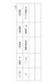
- FIG. 3 is a diagram showing an example of a user database.
- the user database 210 of this embodiment stores user information related to the user P of the device 10.
- the user information of this embodiment includes information items such as a user ID, image data, analysis results, authentication information, and biometric information, and the item "user ID" is associated with the other items.
- the value of the item "User ID” is identification information for identifying the user, and may be identification information common to the external system 400 and the management system 100.
- the value of the item “Image data” is information for identifying image data showing an image 20 captured of the user P to which the device 10 is attached. Specifically, the value of the item “Image data” may be a file name of the image data showing the image 20. Furthermore, the image data showing the image 20 may be stored separately in the auxiliary storage device 23.
- the value of the item "Analysis Result” indicates the result of analyzing the image of device 10 extracted from image 20.
- the value of the item "Analysis Result” may be information indicating the health condition of user P.
- images include still images and moving images.
- a still image may be a single frame image cut out from a moving image.
- the value of the item "authentication information” is information that identifies the facial image data of user P extracted from image 20.
- the facial image data of user P extracted from image 20 is stored in the user database 210 separately from the image data representing image 20.
- the value of the item "Biometric information” is information that identifies the image data of the device 10 extracted from the image 20.
- the image data of the device 10 extracted from the image 20 is stored in the user database 210 separately from the image data representing the image 20.
- the information items shown in FIG. 3 are just an example, and the information items stored in the user database 210 are not limited to the example shown in FIG. 3.
- the user database 210 only needs to store a user ID and the results of the analysis of the biometric information, and does not need to include other information items.
- the user database 210 may include other information items than those shown in FIG. 3.
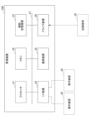
- FIG. 4 is a diagram explaining the functions of each device in the management system.
- the communication unit 310 controls communication between the terminal device 300 and devices other than the terminal device 300.
- the imaging control unit 311 controls the imaging function. Specifically, the imaging control unit 311 acquires image data in response to an operation by the user P.
- the display control unit 312 controls various displays on the display device of the terminal device 300.
- the management device 200 of this embodiment has a user database 210 and an information management unit 220.
- the information management unit 220 includes an information extraction unit 221, an analysis unit 222, a storage control unit 223, and an output unit 224.
- the information extraction unit 221 extracts biometric information and authentication information from the image data acquired from the terminal device 300. In other words, the information extraction unit 221 recognizes the facial image of user P contained in the image 20 indicated by the image data acquired from the terminal device 300, and extracts facial image data as authentication information from the image data indicating the image 20.
- the information extraction unit 221 recognizes the image of the device 10 included in the image 20 indicated by the image data acquired from the terminal device 300, and extracts the image data of the device 10 as biometric information from the image data indicating the image 20. In other words, the information extraction unit 221 acquires information obtained from the device 10.
- the analysis unit 222 analyzes the physical condition of the user P from the biometric information extracted by the information extraction unit 221, and outputs the analysis results.
- the storage control unit 223 stores the authentication information, biometric information, and analysis results extracted by the information extraction unit 221 in the user database 210 in association with the user ID.
- the user ID may be input at the terminal device 300.
- the output unit 224 outputs the analysis results of the biometric information of the user P to the external system 400.
- the device 10 of this embodiment may be, for example, a colorimetric sensor that changes color in response to bodily fluids such as sweat secreted from the human body when attached to the human body.
- the colorimetric sensor may detect the pH of user P's bodily fluids and the content of glucose, lactate, sodium, potassium, chloride ions, lactic acid, uric acid, cortisol, etc. in the bodily fluids.
- the analysis unit 222 may analyze the health condition of the user P based on the color of the image of the device 10. Specifically, the analysis unit 222 may output the presence or absence of diabetes of the user P, blood alcohol concentration, stress level, heat stroke level, etc. as the analysis result.
- the device 10 of this embodiment may be a patch containing a drug that is absorbed into the skin.
- the appearance of the device 10 may change depending on the time that has passed since the user P attached the device 10 to the skin.
- the appearance of the device 10 may be the color of the device 10, the shape of the characters printed on the device 10, etc.
- the analysis unit 222 may analyze the state of administration of the drug to the user P from an image of the device 10.
- the device 10 of this embodiment may also be a non-invasive sensor.
- a non-invasive sensor is, for example, an electrical, optical, or temperature sensor.
- the device 10 may acquire the body temperature, heart rate, blood pressure, and the like of the user P as bioinformation.
- these non-invasive sensors may detect the pH of the user P's body fluids and the content of glucose, lactate, sodium, potassium, chloride ions, lactic acid, uric acid, cortisol, and the like, in the same manner as colorimetric sensors.
- the device 10 may communicate with the terminal device 300 and transmit the bioinformation to the terminal device 300.
- the appearance of the device 10 may further change from the appearance when the device 10 was attached to the human body.
- the appearance of the device 10 will change from the appearance before the device 10 was initially attached to the user P.
- the device 10 may have, for example, a two-dimensional code 11 printed thereon with embedded identification information for identifying the device 10.
- the two-dimensional code 11 of this embodiment may be damaged when the device 10 is attached to a human body and then peeled off from the human body. By providing such a two-dimensional code 11 on the device 10, it is possible to cause a change in the appearance of the device 10 when the device 10 is separated from the human body.
- device 10 may be configured so that when device 10 is peeled off from the human body, letters or the like appear on the surface of device 10 (the surface opposite to the surface that comes into contact with the skin of the human body). Furthermore, device 10 may change color when device 10 is peeled off from the human body.
- the appearance of device 10 after it has been peeled off from the human body needs to be different from the appearance of device 10 when it is attached to the human body to such an extent that it is visually recognizable that device 10 has been peeled off from the human body, and the manner in which the appearance of device 10 is changed is not limited to the above-mentioned examples.
- the device 10 by making the device 10 change in appearance when it is removed from the human body to which it is attached, it is possible to prevent information from being misinterpreted between the user P and a third party.
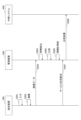
- FIG. 5 is a sequence diagram that explains the operation of the management system.
- the terminal device 300 causes the display control unit 312 to display an input screen for prompting the user P to input a user ID, and accepts the input of the user ID (step S501).
- the terminal device 300 causes the imaging control unit 311 to capture an image of user P with the device 10 attached (step S502), and the communication unit 310 transmits image data representing the captured image 20 to the management device 200 (step S503).
- the information extraction unit 221 extracts the authentication information and biometric information of user P from the image data (step S504). Next, the management device 200 analyzes the biometric information using the analysis unit 222 (step S505).
- the management device 200 causes the storage control unit 223 to associate the authentication information, biometric information, and analysis results of user P and store them in the user database 210 (step S506).
- the biometric information and analysis results stored in the user database 210 are thus confirmed to be information belonging to user P himself.
- the management device 200 receives a request to use the service provided by the external system 400 from the terminal device 300 (step S507).
- This request may include, for example, a user ID.
- the management device 200 When the management device 200 receives this usage request, it retrieves the analysis results of the biometric information associated with the user ID in the user database 210, and outputs them to the external system 400 via the output unit 224 (step S508).
- user P by providing the analysis results of user P's biometric information to the external system 400, user P can use the services provided by the external system 400.
- the device 10 is a colorimetric sensor and the external system 400 is a system that provides services such as medical insurance.
- the management device 200 extracts an image of the device 10 from the image data of the user P who has attached the device 10, and analyzes its color.
- the management device 200 may then store the results of analyzing the color of the image of the device 10 in the user database 210 as information indicating the user's health condition.
- the management device 200 when the management device 200 receives a request from user P to use the external system 400, the management device 200 provides the external system 400 with information indicating the health condition of user P.
- the external system 400 for example, various processes may be performed using the information indicating the health condition of user P.
- highly reliable information can be provided to the external system 400 using information indicating the health condition of user P.
- the device 10 is a patch and the external system 400 is a system that provides a service for managing the medication status of the user P.
- the drug contained in the device 10, which is a patch may be, for example, an angina medication, an asthma medication, a progesterone preparation, a narcotic analgesic, nicotine, etc.
- the management device 200 may store the time when the image data was received in the user database 210 in association with the user ID as the time when administration of the drug to the user P was started.
- the management device 200 may output information to the external system 400 indicating that medication for user P has begun.
- management device 200 may periodically receive image data of user P who has attached device 10 from terminal device 300, and analyze image data showing the image of device 10 extracted from the image data.
- Device 10 which is a patch, may, for example, change color or have letters appear depending on the amount of medication administered to user P. Furthermore, device 10 may change appearance when administration of medication to user P is completed. Specifically, device 10 may change color when administration of medication to user P is completed. In this way, when device 10 is a patch, the appearance of device 10 may change depending on the time that has passed since device 10 was attached to user P.
- the management device 200 may periodically receive image data, analyze the image data showing the image of the device 10, obtain the amount of medication administered to the user P, etc. as the analysis results, and store them in the user database 210 in association with the time the image data was received. The management device 200 may then output the analysis results as information indicating the medication status for the user P to the external system 400.
- the terminal device 300 and the management device 200 are separate devices, but this is not limited to this.
- FIG. 6 is a diagram illustrating the system configuration of a modified management system.
- the terminal device 300A also functions as the management device 200.
- the terminal device 300A has an information management unit 220 that the management device 200 has, and a storage unit 210A that stores user information of the user of the terminal device 300.
- the information management unit 220 associates the analysis results of the biometric information with the authentication information and stores them in the storage unit 210A.
- the terminal device 300A when the terminal device 300A receives a request from the user to use the external system 400, it outputs the analysis results of the biometric information stored in the memory unit 210A to the external system 400.
- the terminal device 300A in FIG. 6 may be realized by downloading a program that realizes the information management unit 220 to the terminal device 300A from a management device (not shown) provided on the Internet.
- the terminal device 300A can obtain the authentication information and the analysis results of the biometric information of the user P from one image data, eliminating the need for the management device 200. Therefore, in the modified example, it is possible to easily link with an external system 400 that uses the analysis results of the biometric information.
Landscapes
- Health & Medical Sciences (AREA)
- Life Sciences & Earth Sciences (AREA)
- Medical Informatics (AREA)
- Public Health (AREA)
- General Health & Medical Sciences (AREA)
- Engineering & Computer Science (AREA)
- Biophysics (AREA)
- Physics & Mathematics (AREA)
- Pathology (AREA)
- Biomedical Technology (AREA)
- Heart & Thoracic Surgery (AREA)
- Molecular Biology (AREA)
- Surgery (AREA)
- Animal Behavior & Ethology (AREA)
- Veterinary Medicine (AREA)
- Primary Health Care (AREA)
- Epidemiology (AREA)
- Measurement Of The Respiration, Hearing Ability, Form, And Blood Characteristics Of Living Organisms (AREA)
Abstract
Description
管理装置200、端末装置300、デバイス10とを含み、管理装置200と端末装置300とは、ネットワークを介して接続される。また、本実施形態の管理装置200は、管理システム100の外部に存在する外部システム400とネットワークを介して接続する。
100、100A 管理システム
200 管理装置
210 ユーザデータベース
220 情報管理部
221 情報抽出部
222 分析部
223 格納制御部
224 出力部
300、300A 端末装置
400 外部システム
Claims (9)
- 人体に貼り付けられて使用されるデバイスと、管理装置とを有する管理システムであって、
前記管理装置は、
前記人体に貼り付けられたデバイスの画像と、前記人体の身体的特徴を示す画像とを含む画像の画像データを取得する取得部と、
前記画像データから、前記人体を特定する認証情報と、前記デバイスから得られる情報とを抽出する抽出部と、
前記デバイスから得られる情報と、前記認証情報とを対応付けて記憶部に格納する格納制御部と、を有する管理システム。 - 前記デバイスから得られる情報は、前記人体の生体情報であり、
前記人体の身体的特徴を示す画像は、前記人体の顔、虹彩、眼球血管、耳の少なくとも何れかを含む画像であり、前記人体を特定する認証情報は、前記人体の身体的特徴を示す画像の画像データであり、
前記管理装置は、
前記人体の生体情報を分析する分析部をさらに有し、
前記格納制御部は、
前記生体情報の分析結果と、前記認証情報とを対応付けて前記記憶部に格納する、請求項1記載の管理システム。 - 前記デバイスは、少なくとも、比色センサ又は非侵襲センサを含む、請求項2記載の管理システム。
- 前記デバイスが前記比色センサ又は非侵襲センサである場合、
前記生体情報は、前記比色センサ又は非侵襲センサの画像を含む画像データであり、
前記生体情報の分析結果は、前記人体の健康状態を示す情報である、請求項3記載の管理システム。 - 前記デバイスは、薬剤を含む貼付剤であり、
前記生体情報は、前記貼付剤の画像を含む画像データであり、
前記生体情報の分析結果は、前記人体に対する投薬の状況を示す情報である、請求項2記載の管理システム。 - 前記格納制御部は、
前記貼付剤の画像を含む画像データを取得した時刻を示す情報を、前記認証情報と対応付けて前記記憶部に格納する、請求項5記載の管理システム。 - 前記デバイスの外観は、前記人体に対する前記薬剤の投与が完了した後に、前記薬剤の投与中の外観から変化する、請求項6記載の管理システム。
- 前記デバイスは、前記人体から剥離される時に外観に変化が生じるデバイスである、請求項1又は2記載の管理システム。
- 人体に貼り付けられて、前記人体から生体情報を取得するデバイスであって、
前記人体から剥離される時に外観に変化が生じるデバイス。
Priority Applications (1)
| Application Number | Priority Date | Filing Date | Title |
|---|---|---|---|
| JP2025510251A JPWO2024203258A1 (ja) | 2023-03-24 | 2024-03-12 |
Applications Claiming Priority (2)
| Application Number | Priority Date | Filing Date | Title |
|---|---|---|---|
| JP2023-047923 | 2023-03-24 | ||
| JP2023047923 | 2023-03-24 |
Publications (1)
| Publication Number | Publication Date |
|---|---|
| WO2024203258A1 true WO2024203258A1 (ja) | 2024-10-03 |
Family
ID=92904545
Family Applications (1)
| Application Number | Title | Priority Date | Filing Date |
|---|---|---|---|
| PCT/JP2024/009455 Ceased WO2024203258A1 (ja) | 2023-03-24 | 2024-03-12 | 管理システム、センサ |
Country Status (2)
| Country | Link |
|---|---|
| JP (1) | JPWO2024203258A1 (ja) |
| WO (1) | WO2024203258A1 (ja) |
Citations (2)
| Publication number | Priority date | Publication date | Assignee | Title |
|---|---|---|---|---|
| WO2021261186A1 (ja) * | 2020-06-26 | 2021-12-30 | 株式会社サン・ワイズ | 情報監視装置、情報管理システム、入国審査方法、入場管理方法、及び情報管理プログラム |
| WO2023017619A1 (ja) * | 2021-08-13 | 2023-02-16 | 株式会社ビキタン | 情報処理システム、情報処理方法、コンピュータプログラムおよび情報処理装置 |
-
2024
- 2024-03-12 WO PCT/JP2024/009455 patent/WO2024203258A1/ja not_active Ceased
- 2024-03-12 JP JP2025510251A patent/JPWO2024203258A1/ja active Pending
Patent Citations (2)
| Publication number | Priority date | Publication date | Assignee | Title |
|---|---|---|---|---|
| WO2021261186A1 (ja) * | 2020-06-26 | 2021-12-30 | 株式会社サン・ワイズ | 情報監視装置、情報管理システム、入国審査方法、入場管理方法、及び情報管理プログラム |
| WO2023017619A1 (ja) * | 2021-08-13 | 2023-02-16 | 株式会社ビキタン | 情報処理システム、情報処理方法、コンピュータプログラムおよび情報処理装置 |
Also Published As
| Publication number | Publication date |
|---|---|
| JPWO2024203258A1 (ja) | 2024-10-03 |
Similar Documents
| Publication | Publication Date | Title |
|---|---|---|
| Tsoi et al. | Applications of artificial intelligence for hypertension management | |
| US10916339B2 (en) | Medication adherence monitoring system and method | |
| US20110093290A1 (en) | Information management system and method for an implantable medical device | |
| US20110090048A1 (en) | Data Transmission Device with User Identification Capability | |
| US20140236922A1 (en) | System, method, and software for positive patient identification | |
| CN111476940B (zh) | 基于自助问诊端的分诊转诊方法及系统 | |
| WO2013136600A1 (ja) | 生体情報配信サーバ、そのためのプログラム及びこれを利用した医療支援システム | |
| WO2019100584A1 (zh) | 基于中医四诊仪的中医治未病管理系统及方法 | |
| JP2003150707A (ja) | 医療用問診装置 | |
| EP3732691B1 (en) | Method and apparatus for providing personalized healthcare advice | |
| JP7373831B2 (ja) | 救急医療支援システム | |
| US20200323448A1 (en) | System of Determining Physiological State | |
| CN111527515A (zh) | 计算机系统、药物建议方法以及程序 | |
| US20230115958A1 (en) | Information disclosure system, server, and information disclosure method | |
| CN109658993A (zh) | 一种基于双终端的中医临床案例采集方法及设备 | |
| US20200137051A1 (en) | Biometric Patient Identity Verification System | |
| KR20160133820A (ko) | 휴대용 단말을 이용한 응급처치용 시스템 및 응급처치 방법 | |
| JP2001128958A (ja) | アイリス・アイリドロジ健康診断管理システム | |
| JP2007188290A (ja) | 医療情報提供システム | |
| US20240074703A1 (en) | Wearable monitor | |
| JP2005276109A (ja) | 固有情報記録装置を用いたデータ検出システム | |
| JP2023097310A (ja) | 情報処理装置、情報処理方法、およびプログラム | |
| KR20220134879A (ko) | 앱 기반의 보호자 안심 시스템 | |
| JP2022105426A (ja) | 学習モデルの生成方法、情報処理方法及びプログラム | |
| AU2020100445A4 (en) | A system and method of representing health data |
Legal Events
| Date | Code | Title | Description |
|---|---|---|---|
| 121 | Ep: the epo has been informed by wipo that ep was designated in this application |
Ref document number: 24779388 Country of ref document: EP Kind code of ref document: A1 |
|
| ENP | Entry into the national phase |
Ref document number: 2025510251 Country of ref document: JP Kind code of ref document: A |
|
| WWE | Wipo information: entry into national phase |
Ref document number: 2025510251 Country of ref document: JP |
|
| NENP | Non-entry into the national phase |
Ref country code: DE |
|
| 122 | Ep: pct application non-entry in european phase |
Ref document number: 24779388 Country of ref document: EP Kind code of ref document: A1 |