WO2024203229A1 - 画像投影装置 - Google Patents
画像投影装置 Download PDFInfo
- Publication number
- WO2024203229A1 WO2024203229A1 PCT/JP2024/009331 JP2024009331W WO2024203229A1 WO 2024203229 A1 WO2024203229 A1 WO 2024203229A1 JP 2024009331 W JP2024009331 W JP 2024009331W WO 2024203229 A1 WO2024203229 A1 WO 2024203229A1
- Authority
- WO
- WIPO (PCT)
- Prior art keywords
- image
- projection device
- vehicle
- hud
- brightness
- Prior art date
- Legal status (The legal status is an assumption and is not a legal conclusion. Google has not performed a legal analysis and makes no representation as to the accuracy of the status listed.)
- Ceased
Links
Images


Classifications
-
- B—PERFORMING OPERATIONS; TRANSPORTING
- B60—VEHICLES IN GENERAL
- B60K—ARRANGEMENT OR MOUNTING OF PROPULSION UNITS OR OF TRANSMISSIONS IN VEHICLES; ARRANGEMENT OR MOUNTING OF PLURAL DIVERSE PRIME-MOVERS IN VEHICLES; AUXILIARY DRIVES FOR VEHICLES; INSTRUMENTATION OR DASHBOARDS FOR VEHICLES; ARRANGEMENTS IN CONNECTION WITH COOLING, AIR INTAKE, GAS EXHAUST OR FUEL SUPPLY OF PROPULSION UNITS IN VEHICLES
- B60K35/00—Instruments specially adapted for vehicles; Arrangement of instruments in or on vehicles
- B60K35/20—Output arrangements, i.e. from vehicle to user, associated with vehicle functions or specially adapted therefor
- B60K35/21—Output arrangements, i.e. from vehicle to user, associated with vehicle functions or specially adapted therefor using visual output, e.g. blinking lights or matrix displays
- B60K35/23—Head-up displays [HUD]
-
- G—PHYSICS
- G02—OPTICS
- G02B—OPTICAL ELEMENTS, SYSTEMS OR APPARATUS
- G02B27/00—Optical systems or apparatus not provided for by any of the groups G02B1/00 - G02B26/00, G02B30/00
- G02B27/01—Head-up displays
-
- G—PHYSICS
- G09—EDUCATION; CRYPTOGRAPHY; DISPLAY; ADVERTISING; SEALS
- G09G—ARRANGEMENTS OR CIRCUITS FOR CONTROL OF INDICATING DEVICES USING STATIC MEANS TO PRESENT VARIABLE INFORMATION
- G09G5/00—Control arrangements or circuits for visual indicators common to cathode-ray tube indicators and other visual indicators
-
- G—PHYSICS
- G09—EDUCATION; CRYPTOGRAPHY; DISPLAY; ADVERTISING; SEALS
- G09G—ARRANGEMENTS OR CIRCUITS FOR CONTROL OF INDICATING DEVICES USING STATIC MEANS TO PRESENT VARIABLE INFORMATION
- G09G5/00—Control arrangements or circuits for visual indicators common to cathode-ray tube indicators and other visual indicators
- G09G5/10—Intensity circuits
-
- G—PHYSICS
- G09—EDUCATION; CRYPTOGRAPHY; DISPLAY; ADVERTISING; SEALS
- G09G—ARRANGEMENTS OR CIRCUITS FOR CONTROL OF INDICATING DEVICES USING STATIC MEANS TO PRESENT VARIABLE INFORMATION
- G09G5/00—Control arrangements or circuits for visual indicators common to cathode-ray tube indicators and other visual indicators
- G09G5/36—Control arrangements or circuits for visual indicators common to cathode-ray tube indicators and other visual indicators characterised by the display of a graphic pattern, e.g. using an all-points-addressable [APA] memory
- G09G5/37—Details of the operation on graphic patterns
- G09G5/377—Details of the operation on graphic patterns for mixing or overlaying two or more graphic patterns
-
- H—ELECTRICITY
- H04—ELECTRIC COMMUNICATION TECHNIQUE
- H04N—PICTORIAL COMMUNICATION, e.g. TELEVISION
- H04N5/00—Details of television systems
- H04N5/74—Projection arrangements for image reproduction, e.g. using eidophor
Definitions
- the present invention relates to an image projection device.
- Image projection devices for vehicles such as that described in Patent Document 1 are known.
- Image projection devices project images or videos onto a windshield or combiner, and allow the occupants to view the images by superimposing them on real space through the windshield or combiner, thereby achieving what is known as augmented reality (AR).
- AR augmented reality
- Patent Document 1 discloses a vehicle display system for reducing the hassle of visibility caused by overlapping of an image created by visible light and an image created by near-infrared light.
- the vehicle display system includes a first lamp that irradiates near-infrared light, a second lamp that irradiates visible light, a first camera that captures a first image of the outside of the vehicle illuminated by the first lamp, a second camera, a control unit, and an image projection device.
- the imaging range of the second camera includes the imaging range of the first camera.
- the second camera captures a second image of the outside of the vehicle illuminated by the second lamp.
- the control unit generates a third image in which the brightness of pixels of the first image corresponding to pixels in the second image is reduced based on the brightness of the second image, and causes the image projection device to display the third image.
- the line of sight of vehicle (mobile body) occupants is constantly changing. For example, sometimes the occupants look at the image generated by the image projection device, and sometimes they do not. If the brightness of the image remains high even when the occupants are not looking at it, the image will be perceived as dazzling by the occupants.
- the present disclosure provides an image projection device that displays an image at a brightness that depends on whether or not an occupant is looking at it.
- An image projection device includes: An image projection device that allows a passenger of a moving body to visually recognize an image as a virtual image, When it is determined that the occupant is not looking at the image, the brightness of the image is reduced.
- This disclosure makes it possible to provide an image projection device that displays an image at a brightness that depends on whether or not an occupant is looking at it.
- FIG. 1 is a block diagram of a vehicle system in a vehicle equipped with an image projection device according to this embodiment.
- FIG. 2 is a schematic diagram of an image projection device.
- FIG. 3 is a diagram illustrating a state in which the image output by the image projection device is recognized by the driver as a virtual image.
- FIG. 4 is a flowchart showing the process executed by the image projection device when displaying an image.
- FIG. 5 is a diagram illustrating an example of an attention-calling image of the image projection device.
- the "left-right direction,” “up-down direction,” and “front-rear direction” may be referred to as appropriate. These directions are relative directions set for the HUD (head-up display) 42 shown in FIG. 2.
- the "left-right direction” refers to a direction that includes the “left direction” and the “right direction.”
- the "up-down direction” refers to a direction that includes the “upward direction” and the “downward direction.”
- the "front-rear direction” refers to a direction that includes the "forward direction” and the "rearward direction.”
- the left-right direction is a direction that is perpendicular to the up-down direction and the front-rear direction. The directions are defined based on the occupant using the HUD 42.
- FIG. 1 is a block diagram of the vehicle system 2.
- the vehicle 1 is an example of a moving body.
- the vehicle system 2 includes a vehicle control unit 3, a HUD 42, and a camera 6.
- the vehicle control unit 3 is configured to control the running of the vehicle 1.
- the vehicle control unit 3 is configured, for example, by at least one electronic control unit (ECU: Electronic Control Unit).
- the electronic control unit includes a computer system (e.g., SoC (System on a Chip) etc.) including one or more processors and one or more memories, and an electronic circuit configured of active elements such as transistors and passive elements.
- the processor includes, for example, at least one of a CPU (Central Processing Unit), an MPU (Micro Processing Unit), a GPU (Graphics Processing Unit) and a TPU (Tensor Processing Unit).
- the CPU may be configured by multiple CPU cores.
- the GPU may be configured by multiple GPU cores.
- the memory includes a ROM (Read Only Memory) and a RAM (Random Access Memory).
- a vehicle control program may be stored in the ROM.
- the vehicle control program may include an artificial intelligence (AI) program for autonomous driving.
- the AI program is a program (trained model) constructed by supervised or unsupervised machine learning (particularly, deep learning) using a multi-layer neural network.
- the RAM may temporarily store the vehicle control program, vehicle control data, and/or surrounding environment information indicating the surrounding environment of the vehicle.
- the processor may be configured to deploy a program designated from various vehicle control programs stored in the ROM onto the RAM and execute various processes in cooperation with the RAM.
- the computer system may also be configured with non-von Neumann type computers such as ASICs (Application Specific Integrated Circuits) and FPGAs (Field-Programmable Gate Arrays). Furthermore, the computer system may be configured with a combination of von Neumann type computers and non-von Neumann type computers.
- ASICs Application Specific Integrated Circuits
- FPGAs Field-Programmable Gate Arrays
- the HUD 42 is located inside the vehicle 1. Specifically, the HUD 42 is installed in a predetermined location inside the vehicle 1. For example, the HUD 42 may be disposed in the dashboard of the vehicle 1.
- the HUD 42 is a visual interface between the vehicle 1 and the occupant.
- the HUD 42 is configured to display predetermined information (hereinafter referred to as HUD information) toward the occupant so that the HUD information is superimposed on the real space outside the vehicle 1 (particularly, the surrounding environment in front of the vehicle). In this manner, the HUD 42 is an AR (Augmented Reality) display.
- the HUD information displayed by the HUD 42 includes, for example, vehicle information related to the running of the vehicle 1, surrounding environment information related to the surrounding environment of the vehicle 1 (particularly, information related to objects present outside the vehicle 1), and attention-attracting images displayed according to the situation of traffic participants around the vehicle.
- vehicle information indicates at least one of the following: vehicle speed, vehicle acceleration/deceleration state, vehicle charging state (charging rate, charging, discharging), and shift position. Details of the HUD 42 will be described later.
- the HUD 42 is an example of an image projection device that allows the occupant of the moving body to visually recognize an image as a virtual image.
- the vehicle control unit 3 and the control board 425 of the HUD 42 which will be described later, are provided as separate components, but the vehicle control unit 3 and the control board 425 may be configured as an integrated unit. In this respect, the control board 425 and the vehicle control unit 3 may be configured as a single electronic control unit.
- the camera 6 is a camera including an imaging element such as a CCD (Charge-Coupled Device) or a CMOS (Complementary Metal Oxide Semiconductor).
- the camera 6 includes one or more external cameras 61 and an internal camera 62.
- the external camera 61 is configured to acquire image data showing the surrounding environment of the vehicle 1 and output the image data to the vehicle control unit 3.
- the vehicle control unit 3 acquires surrounding environment information based on the output image data.
- the surrounding environment information may include information about objects (pedestrians, other vehicles including a preceding vehicle and an oncoming vehicle, signs, etc.) that exist outside the vehicle 1.
- the external camera 61 detects a preceding vehicle traveling in front of the vehicle 1 and outputs image data showing the preceding vehicle to the vehicle control unit 3.
- the vehicle control unit 3 acquires surrounding environment information including information about the preceding vehicle and information about the distance and position of the preceding vehicle relative to the vehicle 1 based on the output image data.
- the external camera 61 may be configured as a mono
- the internal camera 62 is disposed inside the vehicle 1 and configured to acquire image data showing the occupant.
- the internal camera 62 functions as a tracking camera that tracks the occupant's viewpoint E.
- the internal camera 62 may have a light projection function, an image processing function, and an arithmetic processing function required for tracking.
- the occupant's viewpoint E is either the viewpoint of the left eye or the viewpoint of the right eye of the occupant.
- the viewpoint E may be defined as the midpoint of a line segment connecting the viewpoint of the left eye and the viewpoint of the right eye.
- the control board 425 may identify the position of the occupant's viewpoint E based on the image data acquired by the internal camera 62.
- the position of the occupant's viewpoint E is updated at a predetermined cycle based on the image data.
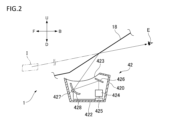
- FIG. 2 is a schematic diagram of the HUD 42 according to this embodiment.
- the HUD 42 has a HUD main body 420.
- the HUD main body 420 has a housing 422 and an exit window 423.
- the exit window 423 is a transparent plate that transmits visible light.
- the HUD main body 420 has an image generation unit (PGU: Picture Generation Unit) 424, a control board 425, a plane mirror 426, a drive mechanism 427, and a concave mirror 428.
- PGU Picture Generation Unit
- the image generating unit 424 is configured to generate an image.
- the image generating unit 424 has a light source, optical components, and a display device.
- the light source is, for example, a laser light source or an LED light source.
- the laser light source is, for example, an RGB laser light source configured to emit red laser light, green laser light, and blue laser light, respectively.
- the optical components include a prism, a lens, a diffusion plate, a magnifying glass, etc.
- the display device is a liquid crystal display, a DMD (Digital Mirror Device), etc.
- the drawing method of the image generating unit 424 may be a raster scan method, a DLP method, or an LCOS method. When the DLP method or the LCOS method is adopted, the light source of the HUD 42 may be an LED light source. Note that, when a liquid crystal display is adopted, the light source of the HUD 42 may be a white LED light source.
- the display device of the image generating unit 424 has an image forming surface formed of a large number of pixels.
- the image generating unit 424 is configured to form an image using a portion of the image forming surface.
- the control board 425 is configured to control the operation of the image generating unit 424 and the drive mechanism 427.
- the control board 425 is equipped with a processor such as a CPU (Central Processing Unit) and a memory 429 ( Figure 1), and the processor executes a computer program read from the memory 429 to control the operation of the image generating unit 424.
- the control board 425 may also control the drive mechanism 427 to change the orientation (angle) of the concave mirror 428.
- the control board 425 acquires information and image data transmitted from the vehicle control unit 3.
- the acquired information or image data includes information related to the occupant's line of sight, vehicle driving information, and surrounding environment information.
- the control board 425 is further configured to generate a control signal for controlling the operation of the image generation unit 424 according to the information and image data, and to transmit the generated control signal to the image generation unit 424. More specifically, the control board 425 is configured to control the brightness (illuminance) of the image generated by the image generation unit 424 according to the acquired information and image data.
- the concave mirror 428 is disposed on the optical path of the light emitted from the image generating unit 424 and reflected by the plane mirror 426. Specifically, the concave mirror 428 is disposed in front of the image generating unit 424 and the plane mirror 426 within the HUD main body 420. The concave mirror 428 is configured to reflect the light emitted by the image generating unit 424 toward the windshield 18 (e.g., the front window of the vehicle 1) via the exit window 423.
- the concave mirror 428 has a concavely curved reflective surface, and reflects the image of the light emitted from the image generating unit 424 and formed at a predetermined magnification.
- the light emitted from the exit window 423 of the HUD main body 420 is irradiated onto the windshield 18.
- a portion of the light irradiated from the HUD main body 420 onto the windshield 18 is reflected towards the occupant's viewpoint E.
- the occupant recognizes the light (predetermined image) emitted from the HUD main body 420 as a virtual image formed at a predetermined distance in front of the windshield 18.
- the image displayed by the HUD 42 is superimposed on the real space in front of the vehicle 1 through the windshield 18, allowing the occupant to visually recognize the virtual image object I formed by the predetermined image as floating above the road outside the vehicle.
- a predetermined image is projected so as to become a virtual image at a single distance that is arbitrarily determined.
- a 3D image stereo image
- a plurality of predetermined images that are the same or different from each other are projected so as to become virtual images at different distances.
- the distance of the virtual image object I (the distance from the occupant's viewpoint E to the virtual image) can be adjusted by adjusting the distance from the image generation unit 424 to the occupant's viewpoint E (for example, by adjusting the distance between the image generation unit 424 and the concave mirror 428).
- the HUD main body 420 does not need to have a plane mirror 426. In this case, the light emitted from the image generation unit 424 is incident on the concave mirror 428 without being reflected by the plane mirror 426.
- Fig. 3 is a diagram illustrating a state in which the image output by the HUD 42 is recognized by the driver as a virtual image.
- Fig. 3 illustrates a state in which an image B1 indicating the vehicle speed is recognized at a predetermined position in the left corner of the driver's field of view A1.
- the image B1 indicating the vehicle speed is an image whose display position is fixed in the driver's field of view A1.
- the image B1 indicating the vehicle speed is an image that indicates the state of the vehicle 1, and is also an image that does not change according to the state ahead of the vehicle 1.
- the driver is an example of a passenger.
- the HUD 42 generates image data to be displayed based on vehicle speed data (e.g., 30 km/h) acquired from the vehicle control unit 3 and basic image data (character font, decorative image, initial brightness, etc.) of the image including initial brightness acquired from the memory 429.
- vehicle speed data e.g., 30 km/h
- basic image data character font, decorative image, initial brightness, etc.
- HUD 42 determines where to display this image data.
- the driver's field of view A1 extends at a specific solid angle ⁇ from eye point (eye position, viewpoint) E.
- HUD 42 determines the display position of the image data so that image B1 indicating the vehicle speed is displayed at a specific position in the driver's field of view A1.
- the HUD 42 can output an image anywhere in the field of view (hereafter referred to as the expected maximum field of view AMax) that the driver can see when the eye point E moves within the expected range of movement (eye box EB).
- the HUD 42 can control the position and direction in which image light is emitted from the exit window 423 of the HUD 42 by changing the position at which the image is formed on the image forming surface 42S or by changing the angle of the concave mirror 428 or the plane mirror 426.
- the image generating area 42R of the HUD 42 is set to be the same as or larger than the expected maximum field of view AMax.
- the HUD 42 calculates the position within the expected maximum field of view AMax at which the image is to be displayed as generated position information.
- the generated position information can be expressed in a format in which any position within the expected maximum field of view AMax is expressed as a solid angle ⁇ with the center of the eye box EB as the central point.
- the generated position information can be calculated based on the position of the driver's eyes (viewpoint E) and the position at which the driver wants to recognize the image within his field of vision A1.
- the position at which the driver wants to recognize the image within his field of vision A1 is stored in advance in memory 429 or the like.
- image B1 indicating vehicle speed is set to be displayed in the lower section of the maximum field of vision AMax when it is divided vertically into thirds.
- HUD 42 determines through eye tracking that the driver's eye position (viewpoint E) is facing the lower section, it sets the display position of image B1 indicating vehicle speed to the lower section as the generated position information.
- the HUD 42 emits image light based on image data including initial brightness and generated position information, allowing the driver to recognize an image B1 indicating the vehicle speed at a specific position within the driver's field of view A1 (for example, the lower level of the maximum field of view AMax).
- the HUD 42 is configured to reduce the brightness of image B1 when it is determined that the driver is not looking at image B1.
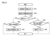
- Figure 4 is a flowchart executed by the HUD 42 when displaying image B1. The HUD 42 repeatedly executes the flow shown in Figure 4 at a predetermined interval, for example, every 0.1 seconds.
- the HUD 42 first outputs image B1 at the initial brightness (step S01).
- the HUD 42 acquires the driver's gaze information (step S02).
- the HUD 42 acquires the driver's gaze information from the internal camera 62 via the vehicle control unit 3.
- the internal camera 62 acquires image data including the driver's eyes as the driver's gaze information.
- the acquired image data is sent to the HUD 42 via the vehicle control unit 3.
- the HUD 42 estimates the direction in which the driver is looking based on the acquired image data, for example, the position of the driver's black eye and the position of the pupil.
- the HUD 42 determines whether the driver is looking at image B1 based on the acquired gaze information (step S03). More specifically, the HUD 42 determines whether the estimated driver's gaze is within the display range BR of image B1, which indicates the vehicle speed. If the driver's gaze is within the display range BR, the HUD 42 determines that the driver is looking at image B1.
- image B1 is set to be recognized as being displayed 3 m ahead of vehicle 1
- the area that the image occupies on a virtual screen 3 m ahead can be represented using a two-dimensional coordinate system based on the generation position information of image B1.
- the direction of the driver's line of sight can also be represented using a common two-dimensional coordinate system on the virtual screen based on the position of the eyes and the direction of the line of sight.
- HUD 42 can determine whether the direction of the line of sight is within the display range BR of image B1.
- the HUD 42 determines whether a predetermined time has elapsed during which the driver has not looked at image B1 (step S04). Here, it determines whether the driver has not looked at image B1 for, for example, three minutes.
- step S04 If image B1 has not been viewed for less than three minutes (step S04: NO), HUD 42 ends the process.
- step S05 the HUD 42 reduces the brightness of image B1 (step S05). For example, the HUD 42 reduces the brightness of image B1 to a brightness that is 60% lower than the initial brightness. After reducing the brightness, the HUD 42 ends the process.
- step S06 HUD 42 next determines whether the brightness of image B1 is set to an initial brightness (step S06).
- HUD42 ends the process.
- step S06 If the initial luminance is not set for the luminance of image B1 (step S06: NO), that is, if the luminance of image B1 has been reduced, HUD 42 returns the luminance to the initial luminance and ends the process. Note that it is preferable that the speed [lux/sec] at which the luminance is increased to the initial luminance in step S07 is faster than the speed at which the luminance is reduced in step S05.
- the HUD 42 of this embodiment reduces the luminance of image B1 when it is determined that the driver is not looking at image B1. If the luminance of image B1 remains high at its initial luminance even when the driver is not looking at image B1, the driver may find image B1 dazzling. However, in this embodiment, the luminance of image B1 is reduced, so the glare of such an image can be reduced. Therefore, it is possible to provide a HUD 42 that displays image B1 at a brightness that corresponds to whether the driver is looking at it or not.
- the brightness of image B1 decreases when a predetermined time has passed while the driver is not looking at image B1.
- the line of sight of the driver of vehicle 1 is constantly moving, and there are cases where the driver's line of sight is within the display range BR of image B1 for a very short period of time, or where the driver passes through the display range BR momentarily. If the brightness of image B1 is changed even in such cases, the driver may find the change in brightness annoying.
- the brightness of image B1 decreases when a predetermined time has passed, making it possible to reduce the annoyance of the change in brightness.
- the rate at which the brightness decreases is relatively slow in order to reduce the annoyance of the change in brightness.
- the driver goes from not looking at image B1 to looking at it, it is preferable to immediately display image B1 at a brightness that is easy for the driver to see.
- the rate at which the brightness increases is faster than the rate at which the brightness decreases, so that when the driver's line of sight returns to image B1, image B1 can be displayed relatively quickly at a brightness that is easy for the driver to see.
- the position at which image B1 is displayed does not change depending on the state ahead of vehicle 1. This reduces the processing load on HUD 42 compared to a case in which the position at which image B1 is displayed changes depending on the state ahead of vehicle 1.
- the position where image B1 is displayed is fixed. Since there is no need to change the position where image B1 is displayed, the processing load on the HUD 42 is relatively reduced.
- image B1 shows the state of vehicle 1. Therefore, image B1 showing the state of vehicle 1 can be provided to the driver.
- image B1 shows information that does not change depending on the state ahead of vehicle 1. Since the displayed image B1 does not need to be linked to the state ahead of vehicle 1, the processing load on HUD 42 is relatively reduced.
- the HUD 42 may also project an attention-calling image C1 that is displayed according to the conditions of traffic participants around the vehicle 1.
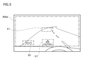
- Figure 5 is a diagram illustrating an example of the attention-calling image C1 of the HUD 42.
- a motorcycle (an example of a traffic participant) may be approaching from behind the vehicle 1. Because the motorcycle is located outside the driver's field of vision A1, the driver has difficulty noticing it.
- the HUD 42 may receive information regarding the direction and speed of the approaching motorcycle via the external camera 61 of the vehicle 1, and display an attention-calling image C1 to notify the driver of the presence of the motorcycle.
- the attention-calling image C1 may be displayed at a position different from the image B1 showing the state of the vehicle 1 and the driver's line of sight E1. As shown in FIG. 5, for example, the attention-calling image C1 may be displayed at the bottom center of the driver's maximum visual field AMax.
- the attention warning image C1 is displayed at a higher brightness than the image B1, whose brightness changes according to the driver's line of sight. More specifically, the brightness of the attention warning image C1 is higher than the maximum brightness of the image B1, or the brightness of the attention warning image C1 is higher than the brightness of the image B1 currently being displayed.
- the HUD 42 of this embodiment projects an image B1 showing the state of the vehicle 1, as well as an attention-calling image C1 that is displayed according to the status of traffic participants around the vehicle 1. This makes it easier for the driver to recognize the presence of traffic participants, such as motorcycles, approaching the vehicle 1 from outside the maximum field of view AMax.
- the brightness of the attention warning image C1 may be higher than when the driver is looking at the motorcycle.
- the HUD 42 acquires the driver's line of sight information via the internal camera 62 and can determine whether the driver is looking at the motorcycle. If the driver has never looked directly at the motorcycle, it is highly likely that the driver is not aware of the presence of the motorcycle. In this embodiment, in such a case, the brightness of the attention warning image C1 is relatively high, making it easier for the driver to recognize the presence of the motorcycle.
- the brightness of image B1 may be lower than when the driver is not looking at the motorcycle.
- the driver is looking at the motorcycle, there is a high possibility that the driver is aware of the motorcycle's presence. If the brightness of image B1 other than the attention-drawing image C1 is high even in such a case, the driver may find the image B1 dazzling. In this embodiment, the brightness of image B1 is low in such a case, and therefore the glare of image B1 can be reduced.
- the driver is shown viewing the image, but the present disclosure can also be applied to cases where an occupant other than the driver, such as a passenger in the front passenger seat or in the back seat, views the image.
- a motorcycle is used as an example of a traffic participant, but traffic participants are not limited to motorcycles. Traffic participants may also be pedestrians, bicycles, or other vehicles.
- the virtual screen is set 3 m ahead of the vehicle 1, but the position of the virtual screen is not limited to 3 m ahead.
- the virtual screen may be set 10 m ahead of the vehicle 1.
Landscapes
- Engineering & Computer Science (AREA)
- Physics & Mathematics (AREA)
- General Physics & Mathematics (AREA)
- Theoretical Computer Science (AREA)
- Computer Hardware Design (AREA)
- Signal Processing (AREA)
- Multimedia (AREA)
- Optics & Photonics (AREA)
- Chemical & Material Sciences (AREA)
- Combustion & Propulsion (AREA)
- Transportation (AREA)
- Mechanical Engineering (AREA)
- Instrument Panels (AREA)
Abstract
Description
虚像として移動体の乗員に画像を視認させる画像投影装置であって、
前記乗員が前記画像を見ていないと判定したとき、前記画像の輝度を下げる。
図3は、HUD42が出力する画像を虚像として運転者に認識させている様子を例示する図である。図3においては、運転者の視野A1の左隅の所定の位置に車速を示す画像B1を認識させる様子を示している。なお、車速を示す画像B1は、運転者の視野A1のうち、表示される位置が固定されている画像である。車速を示す画像B1は、車両1の状態を示す画像であり、また、車両1の前方の様子に応じて変化しない画像でもある。運転者は、乗員の一例である。
Claims (10)
- 虚像として移動体の乗員に画像を視認させる画像投影装置であって、
前記乗員が前記画像を見ていないと判定したとき、前記画像の輝度を下げる、画像投影装置。 - 前記乗員が前記画像を見ていない状態が所定時間経過したとき、前記画像の前記輝度が下がる、請求項1に記載の画像投影装置。
- 前記乗員が前記画像を見ていない状態から見た状態になったとき、前記画像の前記輝度が上がり、
前記輝度の上がる速度は前記輝度の下がる速度よりも早い、請求項1に記載の画像投影装置。 - 前記画像が表示される位置は、前記移動体の前方の様子に応じて変化しない、請求項1に記載の画像投影装置。
- 前記画像が表示される位置は固定されている、請求項1に記載の画像投影装置。
- 前記画像は前記移動体の状態を示す、請求項1に記載の画像投影装置。
- 前記画像は前記移動体の前方の様子に応じて変化しない情報を示す、請求項1に記載の画像投影装置。
- 前記画像投影装置は、
前記移動体の状態を示す前記画像と、
前記移動体の周囲の交通参加者の状況に応じて表示する注意喚起画像と、を照射し、
前記注意喚起画像は、前記乗員の視線に応じて前記輝度が変化する前記画像よりも高い輝度で表示される、請求項1に記載の画像投影装置。 - 前記乗員が前記交通参加者を見ていないときは、前記乗員が前記交通参加者を見ているときに比べて、前記注意喚起画像の前記輝度が高い、請求項8に記載の画像投影装置。
- 前記乗員が前記移動体の周囲の交通参加者を見ているときは、前記乗員が前記交通参加者を見ていないときに比べて、前記画像の前記輝度が低い、請求項1に記載の画像投影装置。
Priority Applications (1)
| Application Number | Priority Date | Filing Date | Title |
|---|---|---|---|
| JP2025510233A JPWO2024203229A1 (ja) | 2023-03-29 | 2024-03-11 |
Applications Claiming Priority (2)
| Application Number | Priority Date | Filing Date | Title |
|---|---|---|---|
| JP2023-053673 | 2023-03-29 | ||
| JP2023053673 | 2023-03-29 |
Publications (1)
| Publication Number | Publication Date |
|---|---|
| WO2024203229A1 true WO2024203229A1 (ja) | 2024-10-03 |
Family
ID=92904317
Family Applications (1)
| Application Number | Title | Priority Date | Filing Date |
|---|---|---|---|
| PCT/JP2024/009331 Ceased WO2024203229A1 (ja) | 2023-03-29 | 2024-03-11 | 画像投影装置 |
Country Status (2)
| Country | Link |
|---|---|
| JP (1) | JPWO2024203229A1 (ja) |
| WO (1) | WO2024203229A1 (ja) |
Citations (7)
| Publication number | Priority date | Publication date | Assignee | Title |
|---|---|---|---|---|
| JPH10963A (ja) * | 1996-04-16 | 1998-01-06 | Harness Sogo Gijutsu Kenkyusho:Kk | 車両の表示装置 |
| JPH10100739A (ja) * | 1996-09-27 | 1998-04-21 | Fujitsu Ten Ltd | ヘッドアップディスプレイ装置 |
| JP2014199546A (ja) * | 2013-03-29 | 2014-10-23 | 富士通株式会社 | 運転支援装置及び運転支援方法 |
| JP2015060180A (ja) * | 2013-09-20 | 2015-03-30 | 日本精機株式会社 | ヘッドアップディスプレイ装置 |
| WO2017018027A1 (ja) * | 2015-07-29 | 2017-02-02 | 富士フイルム株式会社 | 投写型表示装置及び投写制御方法 |
| WO2017018122A1 (ja) * | 2015-07-29 | 2017-02-02 | 富士フイルム株式会社 | 投写型表示装置及び投写制御方法 |
| JP2018052281A (ja) * | 2016-09-28 | 2018-04-05 | 矢崎総業株式会社 | 車両用表示装置 |
-
2024
- 2024-03-11 JP JP2025510233A patent/JPWO2024203229A1/ja active Pending
- 2024-03-11 WO PCT/JP2024/009331 patent/WO2024203229A1/ja not_active Ceased
Patent Citations (7)
| Publication number | Priority date | Publication date | Assignee | Title |
|---|---|---|---|---|
| JPH10963A (ja) * | 1996-04-16 | 1998-01-06 | Harness Sogo Gijutsu Kenkyusho:Kk | 車両の表示装置 |
| JPH10100739A (ja) * | 1996-09-27 | 1998-04-21 | Fujitsu Ten Ltd | ヘッドアップディスプレイ装置 |
| JP2014199546A (ja) * | 2013-03-29 | 2014-10-23 | 富士通株式会社 | 運転支援装置及び運転支援方法 |
| JP2015060180A (ja) * | 2013-09-20 | 2015-03-30 | 日本精機株式会社 | ヘッドアップディスプレイ装置 |
| WO2017018027A1 (ja) * | 2015-07-29 | 2017-02-02 | 富士フイルム株式会社 | 投写型表示装置及び投写制御方法 |
| WO2017018122A1 (ja) * | 2015-07-29 | 2017-02-02 | 富士フイルム株式会社 | 投写型表示装置及び投写制御方法 |
| JP2018052281A (ja) * | 2016-09-28 | 2018-04-05 | 矢崎総業株式会社 | 車両用表示装置 |
Also Published As
| Publication number | Publication date |
|---|---|
| JPWO2024203229A1 (ja) | 2024-10-03 |
Similar Documents
| Publication | Publication Date | Title |
|---|---|---|
| JP7254832B2 (ja) | ヘッドアップディスプレイ、車両用表示システム、及び車両用表示方法 | |
| JP7241081B2 (ja) | 車両用表示システム及び車両 | |
| JP7478160B2 (ja) | ヘッドアップディスプレイおよび画像表示システム | |
| JP7295863B2 (ja) | 車両用表示システム及び車両 | |
| US11597316B2 (en) | Vehicle display system and vehicle | |
| JP6695062B2 (ja) | 表示システム、制御装置、制御方法、プログラム、及び移動体 | |
| JP7545400B2 (ja) | 車両用表示システム及び車両 | |
| JP7727643B2 (ja) | 車両用表示システム及び画像照射装置 | |
| US12005832B2 (en) | Vehicle display system, vehicle system, and vehicle | |
| JP7652970B2 (ja) | 画像生成装置及びヘッドアップディスプレイ | |
| JP7602593B2 (ja) | ヘッドアップディスプレイ | |
| JP7619007B2 (ja) | 表示制御装置、ヘッドアップディスプレイ装置、及び表示制御方法 | |
| EP3961291B1 (en) | Vehicular head-up display and light source unit used therefor | |
| JP2024141826A (ja) | 画像投影装置 | |
| US20250306366A1 (en) | Image generating apparatus and image projecting apparatus | |
| JP7635559B2 (ja) | 表示制御装置、ヘッドアップディスプレイ装置、及び表示制御方法 | |
| WO2023190338A1 (ja) | 画像照射装置 | |
| JP7773612B2 (ja) | 画像生成装置及びヘッドアップディスプレイ | |
| JP7780574B2 (ja) | ヘッドアップディスプレイ |
Legal Events
| Date | Code | Title | Description |
|---|---|---|---|
| 121 | Ep: the epo has been informed by wipo that ep was designated in this application |
Ref document number: 24779359 Country of ref document: EP Kind code of ref document: A1 |
|
| ENP | Entry into the national phase |
Ref document number: 2025510233 Country of ref document: JP Kind code of ref document: A |
|
| WWE | Wipo information: entry into national phase |
Ref document number: 2025510233 Country of ref document: JP |
|
| NENP | Non-entry into the national phase |
Ref country code: DE |
|
| 122 | Ep: pct application non-entry in european phase |
Ref document number: 24779359 Country of ref document: EP Kind code of ref document: A1 |