WO2024203127A1 - 管理装置、管理装置を有する体外循環管理装置、管理装置の作動方法及び管理装置の作動プログラム - Google Patents
管理装置、管理装置を有する体外循環管理装置、管理装置の作動方法及び管理装置の作動プログラム Download PDFInfo
- Publication number
- WO2024203127A1 WO2024203127A1 PCT/JP2024/008829 JP2024008829W WO2024203127A1 WO 2024203127 A1 WO2024203127 A1 WO 2024203127A1 JP 2024008829 W JP2024008829 W JP 2024008829W WO 2024203127 A1 WO2024203127 A1 WO 2024203127A1
- Authority
- WO
- WIPO (PCT)
- Prior art keywords
- information
- displayed
- management device
- display
- display area
- Prior art date
- Legal status (The legal status is an assumption and is not a legal conclusion. Google has not performed a legal analysis and makes no representation as to the accuracy of the status listed.)
- Ceased
Links
Images


Classifications
-
- A—HUMAN NECESSITIES
- A61—MEDICAL OR VETERINARY SCIENCE; HYGIENE
- A61M—DEVICES FOR INTRODUCING MEDIA INTO, OR ONTO, THE BODY; DEVICES FOR TRANSDUCING BODY MEDIA OR FOR TAKING MEDIA FROM THE BODY; DEVICES FOR PRODUCING OR ENDING SLEEP OR STUPOR
- A61M1/00—Suction or pumping devices for medical purposes; Devices for carrying-off, for treatment of, or for carrying-over, body-liquids; Drainage systems
- A61M1/36—Other treatment of blood in a by-pass of the natural circulatory system, e.g. temperature adaptation, irradiation ; Extra-corporeal blood circuits
- A61M1/3621—Extra-corporeal blood circuits
- A61M1/3666—Cardiac or cardiopulmonary bypass, e.g. heart-lung machines
-
- A—HUMAN NECESSITIES
- A61—MEDICAL OR VETERINARY SCIENCE; HYGIENE
- A61M—DEVICES FOR INTRODUCING MEDIA INTO, OR ONTO, THE BODY; DEVICES FOR TRANSDUCING BODY MEDIA OR FOR TAKING MEDIA FROM THE BODY; DEVICES FOR PRODUCING OR ENDING SLEEP OR STUPOR
- A61M1/00—Suction or pumping devices for medical purposes; Devices for carrying-off, for treatment of, or for carrying-over, body-liquids; Drainage systems
- A61M1/36—Other treatment of blood in a by-pass of the natural circulatory system, e.g. temperature adaptation, irradiation ; Extra-corporeal blood circuits
- A61M1/3601—Extra-corporeal circuits in which the blood fluid passes more than once through the treatment unit
-
- A—HUMAN NECESSITIES
- A61—MEDICAL OR VETERINARY SCIENCE; HYGIENE
- A61M—DEVICES FOR INTRODUCING MEDIA INTO, OR ONTO, THE BODY; DEVICES FOR TRANSDUCING BODY MEDIA OR FOR TAKING MEDIA FROM THE BODY; DEVICES FOR PRODUCING OR ENDING SLEEP OR STUPOR
- A61M1/00—Suction or pumping devices for medical purposes; Devices for carrying-off, for treatment of, or for carrying-over, body-liquids; Drainage systems
- A61M1/14—Dialysis systems; Artificial kidneys; Blood oxygenators ; Reciprocating systems for treatment of body fluids, e.g. single needle systems for hemofiltration or pheresis
- A61M1/16—Dialysis systems; Artificial kidneys; Blood oxygenators ; Reciprocating systems for treatment of body fluids, e.g. single needle systems for hemofiltration or pheresis with membranes
- A61M1/1601—Control or regulation
- A61M1/1613—Profiling or modelling of patient or predicted treatment evolution or outcome
-
- A—HUMAN NECESSITIES
- A61—MEDICAL OR VETERINARY SCIENCE; HYGIENE
- A61M—DEVICES FOR INTRODUCING MEDIA INTO, OR ONTO, THE BODY; DEVICES FOR TRANSDUCING BODY MEDIA OR FOR TAKING MEDIA FROM THE BODY; DEVICES FOR PRODUCING OR ENDING SLEEP OR STUPOR
- A61M1/00—Suction or pumping devices for medical purposes; Devices for carrying-off, for treatment of, or for carrying-over, body-liquids; Drainage systems
- A61M1/36—Other treatment of blood in a by-pass of the natural circulatory system, e.g. temperature adaptation, irradiation ; Extra-corporeal blood circuits
- A61M1/3621—Extra-corporeal blood circuits
- A61M1/3639—Blood pressure control, pressure transducers specially adapted therefor
-
- G—PHYSICS
- G16—INFORMATION AND COMMUNICATION TECHNOLOGY [ICT] SPECIALLY ADAPTED FOR SPECIFIC APPLICATION FIELDS
- G16H—HEALTHCARE INFORMATICS, i.e. INFORMATION AND COMMUNICATION TECHNOLOGY [ICT] SPECIALLY ADAPTED FOR THE HANDLING OR PROCESSING OF MEDICAL OR HEALTHCARE DATA
- G16H20/00—ICT specially adapted for therapies or health-improving plans, e.g. for handling prescriptions, for steering therapy or for monitoring patient compliance
- G16H20/40—ICT specially adapted for therapies or health-improving plans, e.g. for handling prescriptions, for steering therapy or for monitoring patient compliance relating to mechanical, radiation or invasive therapies, e.g. surgery, laser therapy, dialysis or acupuncture
-
- G—PHYSICS
- G16—INFORMATION AND COMMUNICATION TECHNOLOGY [ICT] SPECIALLY ADAPTED FOR SPECIFIC APPLICATION FIELDS
- G16H—HEALTHCARE INFORMATICS, i.e. INFORMATION AND COMMUNICATION TECHNOLOGY [ICT] SPECIALLY ADAPTED FOR THE HANDLING OR PROCESSING OF MEDICAL OR HEALTHCARE DATA
- G16H40/00—ICT specially adapted for the management or administration of healthcare resources or facilities; ICT specially adapted for the management or operation of medical equipment or devices
- G16H40/60—ICT specially adapted for the management or administration of healthcare resources or facilities; ICT specially adapted for the management or operation of medical equipment or devices for the operation of medical equipment or devices
- G16H40/63—ICT specially adapted for the management or administration of healthcare resources or facilities; ICT specially adapted for the management or operation of medical equipment or devices for the operation of medical equipment or devices for local operation
-
- A—HUMAN NECESSITIES
- A61—MEDICAL OR VETERINARY SCIENCE; HYGIENE
- A61M—DEVICES FOR INTRODUCING MEDIA INTO, OR ONTO, THE BODY; DEVICES FOR TRANSDUCING BODY MEDIA OR FOR TAKING MEDIA FROM THE BODY; DEVICES FOR PRODUCING OR ENDING SLEEP OR STUPOR
- A61M1/00—Suction or pumping devices for medical purposes; Devices for carrying-off, for treatment of, or for carrying-over, body-liquids; Drainage systems
- A61M1/36—Other treatment of blood in a by-pass of the natural circulatory system, e.g. temperature adaptation, irradiation ; Extra-corporeal blood circuits
- A61M1/3621—Extra-corporeal blood circuits
- A61M1/3666—Cardiac or cardiopulmonary bypass, e.g. heart-lung machines
- A61M1/3667—Cardiac or cardiopulmonary bypass, e.g. heart-lung machines with assisted venous return
-
- A—HUMAN NECESSITIES
- A61—MEDICAL OR VETERINARY SCIENCE; HYGIENE
- A61M—DEVICES FOR INTRODUCING MEDIA INTO, OR ONTO, THE BODY; DEVICES FOR TRANSDUCING BODY MEDIA OR FOR TAKING MEDIA FROM THE BODY; DEVICES FOR PRODUCING OR ENDING SLEEP OR STUPOR
- A61M2202/00—Special media to be introduced, removed or treated
- A61M2202/0021—Special media to be introduced, removed or treated removed from and reintroduced into the body, e.g. after treatment
-
- A—HUMAN NECESSITIES
- A61—MEDICAL OR VETERINARY SCIENCE; HYGIENE
- A61M—DEVICES FOR INTRODUCING MEDIA INTO, OR ONTO, THE BODY; DEVICES FOR TRANSDUCING BODY MEDIA OR FOR TAKING MEDIA FROM THE BODY; DEVICES FOR PRODUCING OR ENDING SLEEP OR STUPOR
- A61M2202/00—Special media to be introduced, removed or treated
- A61M2202/04—Liquids
- A61M2202/0413—Blood
-
- A—HUMAN NECESSITIES
- A61—MEDICAL OR VETERINARY SCIENCE; HYGIENE
- A61M—DEVICES FOR INTRODUCING MEDIA INTO, OR ONTO, THE BODY; DEVICES FOR TRANSDUCING BODY MEDIA OR FOR TAKING MEDIA FROM THE BODY; DEVICES FOR PRODUCING OR ENDING SLEEP OR STUPOR
- A61M2205/00—General characteristics of the apparatus
- A61M2205/18—General characteristics of the apparatus with alarm
-
- A—HUMAN NECESSITIES
- A61—MEDICAL OR VETERINARY SCIENCE; HYGIENE
- A61M—DEVICES FOR INTRODUCING MEDIA INTO, OR ONTO, THE BODY; DEVICES FOR TRANSDUCING BODY MEDIA OR FOR TAKING MEDIA FROM THE BODY; DEVICES FOR PRODUCING OR ENDING SLEEP OR STUPOR
- A61M2205/00—General characteristics of the apparatus
- A61M2205/50—General characteristics of the apparatus with microprocessors or computers
- A61M2205/502—User interfaces, e.g. screens or keyboards
-
- A—HUMAN NECESSITIES
- A61—MEDICAL OR VETERINARY SCIENCE; HYGIENE
- A61M—DEVICES FOR INTRODUCING MEDIA INTO, OR ONTO, THE BODY; DEVICES FOR TRANSDUCING BODY MEDIA OR FOR TAKING MEDIA FROM THE BODY; DEVICES FOR PRODUCING OR ENDING SLEEP OR STUPOR
- A61M2205/00—General characteristics of the apparatus
- A61M2205/58—Means for facilitating use, e.g. by people with impaired vision
- A61M2205/583—Means for facilitating use, e.g. by people with impaired vision by visual feedback
- A61M2205/584—Means for facilitating use, e.g. by people with impaired vision by visual feedback having a color code
-
- A—HUMAN NECESSITIES
- A61—MEDICAL OR VETERINARY SCIENCE; HYGIENE
- A61M—DEVICES FOR INTRODUCING MEDIA INTO, OR ONTO, THE BODY; DEVICES FOR TRANSDUCING BODY MEDIA OR FOR TAKING MEDIA FROM THE BODY; DEVICES FOR PRODUCING OR ENDING SLEEP OR STUPOR
- A61M2230/00—Measuring parameters of the user
- A61M2230/20—Blood composition characteristics
- A61M2230/205—Blood composition characteristics partial oxygen pressure (P-O2)
-
- A—HUMAN NECESSITIES
- A61—MEDICAL OR VETERINARY SCIENCE; HYGIENE
- A61M—DEVICES FOR INTRODUCING MEDIA INTO, OR ONTO, THE BODY; DEVICES FOR TRANSDUCING BODY MEDIA OR FOR TAKING MEDIA FROM THE BODY; DEVICES FOR PRODUCING OR ENDING SLEEP OR STUPOR
- A61M2230/00—Measuring parameters of the user
- A61M2230/20—Blood composition characteristics
- A61M2230/207—Blood composition characteristics hematocrit
Definitions
- the present invention relates to a management device that manages, for example, pulmonary circulation, which oxygenates a patient's blood outside the body and returns it to the body, an extracorporeal circulation management device that has a management device, an operating method for the management device, and an operating program for the management device.
- extracorporeal circulation devices have been used that perform pulmonary circulation or the like, in which blood from a patient is drawn outside the body, oxygenated using an artificial lung or the like, and returned to the body.
- Such an extracorporeal circulator has a management device that manages the device, and the management device has a display (graphical user interface or the like) that displays various data related to the extracorporeal circulator (for example, Patent Document 1).
- the displays of the management devices thereof have also been made smaller.
- the present invention therefore aims to provide a management device having a display unit such as a display that is easily visible to a user, an extracorporeal circulation device having a management device, an operation method for an extracorporeal circulation device, and a control program for an extracorporeal circulation device.
- a management device for managing an extracorporeal circulation device having an artificial lung device, a pump unit, and an extracorporeal circulation circuit
- the management device having a display unit that displays various information related to the extracorporeal circulation device, the display unit having a first display area in which fixed information that is information fixed in advance is displayed, and a second display area in which the displayed information is changeable, and the second display area is capable of displaying trend graph information generated from the fixed information displayed in the first display area, and is also capable of displaying non-fixed information related to the fixed information.
- the first display area of the display unit constantly displays fixed numerical information such as important information of the extracorporeal circulation device, such as flow rate, pump RPM, FI, etc.
- the second display area constantly displays non-fixed information such as trend graphs of fixed information within a specified period of time and values of the pressure gauge of the extracorporeal circulation circuit, and the display can be changed as needed. Therefore, the user can quickly and reliably grasp the necessary information even on a small display.
- the numerical values and the like that should be visually confirmed first may not be easily recognized.
- the demand is particularly high in emergency situations where extracorporeal circulation devices are used. In this regard, with the above-described configuration, even a less skilled person can easily and quickly recognize the numerical values and the like that should be visually recognized first.
- the management device of (1) above is preferably characterized in that the setting screen for the non-fixed information displayed in the second display area can be displayed in place of the non-fixed information.
- the setting screen for non-fixed information displayed in the second display area can be displayed in place of the non-fixed information, allowing the user to easily and quickly make settings, etc.
- the management device of (2) above is preferably characterized in that the setting screen has a time display area, and the time display area is capable of displaying elapsed time information starting from the current setting time.
- the management devices described above in (1) to (3) are preferably characterized in that the time axis of the time information displaying the trend graph information can be changed.
- the time axis of the time information displaying the trend graph information can be changed, so the user can change the time axis as required (e.g., 24 hours, 12 hours, etc.) to display the trend graph information.
- the management device of (1) to (4) above preferably has an abnormal value information detection unit that detects abnormal value information about the fixed information and the non-fixed information, and the fixed information and the non-fixed information are displayed separated by different frames for each piece of fixed information and non-fixed information, and when the abnormal value information detection unit detects an abnormality in at least one piece of fixed information and non-fixed information, the abnormal frame, which is the frame for at least one piece of fixed information and non-fixed information in which the abnormality has been detected, is displayed in an alarm color that is a color different from the background color of the display unit.
- the abnormality frame for at least one of the fixed information and the non-fixed information for which an abnormality has been detected by the abnormal value information detection unit is displayed in an alarm color that is different from the background color of the display unit, allowing the user to quickly grasp the abnormal value information.
- the management device of (5) above is characterized in that the alarm color is displayed in a number of different colors depending on the degree of priority of the alarm.
- the alarm color has multiple different colors (red, yellow, etc.) depending on the level of priority of the alarm, so the user can instantly determine the level (priority) of the alarm from the color.
- the management device of (5) or (6) above is preferably characterized in that an icon section indicating the content of the abnormality is displayed in the abnormality frame section.
- an icon showing the abnormality is displayed in the abnormality frame, allowing the user to instantly understand the abnormal value by visually checking the icon.
- the management device of (7) above is preferably characterized in that the icon portion is an upward arrow when the abnormality exceeds an upper limit value, and is a downward arrow when the abnormality exceeds a lower limit value.
- the icon is displayed as an upward arrow when the abnormal value exceeds the upper limit, and as a downward arrow when the abnormal value exceeds the lower limit, so the user can instantly grasp the nature of the abnormality.
- the management device of (5) to (8) above preferably has an abnormality information display unit that displays the abnormality information content related to the abnormality frame, and the abnormality information display unit is configured to be displayed in a scrolling manner and is configured to simultaneously display information on the number of abnormal values detected by the abnormal value information detection unit within a certain period of time.
- the abnormality information display section (air bubble detection alarm, etc.) which displays the abnormality information content related to the abnormality frame section, the user can grasp the specific abnormality content and the number of abnormalities. Furthermore, according to the above configuration, the number of pieces of abnormal value information detected by the abnormal value information detection section is also displayed at the same time, so that the number of pieces of abnormal value information can be accurately grasped.
- the management device of (1) to (9) above is preferably characterized in that when multiple pieces of pressure information are displayed as the non-fixed information in the second display area, the multiple pieces of pressure information are displayed in parallel in an order corresponding to the blood supply direction of the extracorporeal circulation device.
- the management device of (1) to (10) above is preferably configured to switch between a plurality of types of the non-fixed information in the second display area and display them in a predetermined order.
- multiple types of non-fixed information are switched and displayed in a predetermined order in the second display area, so the user can easily and quickly grasp all of these multiple non-fixed information at an easily visible size.
- an extracorporeal circulation device having an artificial lung device, a pump unit, an extracorporeal circulation circuit, and a management device
- the management device having a display unit that displays various information related to the extracorporeal circulation device, the display unit having a first display area in which fixed information that is information fixed in advance is displayed, and a second display area in which the displayed information is changeable, and the second display area is capable of displaying trend graph information generated from the fixed information displayed in the first display area, and is also capable of displaying non-fixed information related to the fixed information.
- the above object is achieved in the present invention (13) by a method for controlling a management device that manages an extracorporeal circulation device having an artificial lung device, a pump unit, and an extracorporeal circulation circuit, the management device having a display unit that displays various information related to the extracorporeal circulation device, the display unit having a first display area in which fixed information that is information fixed in advance is displayed, and a second display area in which the displayed information is changeable, and the second display area is capable of displaying trend graph information generated from the fixed information displayed in the first display area, and is also capable of displaying non-fixed information related to the fixed information.
- the above object is achieved in the present invention (14) by a control program of a management device that manages an extracorporeal circulation device having an artificial lung device, a pump unit, and an extracorporeal circulation circuit, the management device having a display unit that displays various information related to the extracorporeal circulation device, the display unit having a first display area in which fixed information that is information fixed in advance is displayed, and a second display area in which the displayed information is changeable, and by an operation program of the management device for realizing a function of displaying trend graph information of the fixed information displayed in the first display area in the second display area, and a function of enabling non-fixed information related to the fixed information to be displayed in the second display area.
- the present invention has the advantage of being able to provide a management device having a display unit such as a display that is easily visible to a user, an extracorporeal circulation device having a management device, an operation method for an extracorporeal circulation device, and a control program for an extracorporeal circulation device.
- FIG. 1 is a schematic diagram showing a main configuration of an extracorporeal circulator 1 according to an embodiment of the present invention.
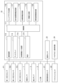
- FIG. 2 is a schematic block diagram showing the main configuration of a controller 10 and the like in FIG. 1 .
- FIG. 2 is a schematic explanatory diagram showing a "first screen 200.”
- FIG. 2 is a schematic explanatory diagram showing a second screen 300.
- 13 is a schematic diagram showing an example of a screen of the lower display 422 on the lower side of the third screen 400.
- FIG. 11 is a schematic explanatory diagram showing a "fourth screen 500" that displays information of the optional flow sensor 17 on the display 113.
- FIG. 13 is another schematic explanatory diagram showing the “fourth screen 500” that displays information of the optional flow sensor 17 on the display 113.
- FIG. 1 is a schematic diagram showing a main configuration of an extracorporeal circulator 1 according to an embodiment of the present invention.
- FIG. 2 is a schematic block diagram showing the main configuration of
- FIG. 13 is a schematic explanatory diagram showing an example of a screen in which the time axis is changed to 24 hours.
- FIG. 13 is a schematic explanatory diagram showing an example of a screen in which the time axis is changed to 12 hours.
- 13 is an example of a pressure setting screen.
- FIG. 13 is a schematic explanatory diagram showing a pressure warning setting screen.
- 13 is an example of an oxygen saturation alarm setting screen.
- FIG. 13 is a schematic diagram showing an SO2-1 alarm setting screen.
- 13 is an example of a hemoglobin/hematocrit value setting screen.
- FIG. 13 is a schematic diagram showing a hematocrit value setting screen.
- FIG. 13 is a schematic explanatory diagram showing an aspect of the elapsed time display of CAL implementation.
- FIG. 13 is a schematic explanatory diagram showing an aspect of the elapsed time display of CAL implementation.
- FIG. 11 is a schematic explanatory diagram showing the display 113 in a state in which an alarm is displayed.
- FIG. 11 is a schematic explanatory diagram showing an example in which three pieces of abnormality content text information are displayed on the display 113.
- FIG. 11 is a schematic explanatory diagram showing an example in which four pieces of abnormality content text information are displayed on the display 113.
- FIG. 1 is a schematic diagram showing the main configuration of an extracorporeal circulator 1 according to an embodiment of the present invention.
- the extracorporeal circulation device 1 is a device for performing extracorporeal circulation of blood of a subject, for example, a patient P.
- the patient P may have a heart that does not function normally, or a heart that functions normally but lungs that do not function normally.
- the extracorporeal circulation device 1 according to the present embodiment shown in FIG. 1 is used, for example, when performing cardiac surgery on a patient P and in the subsequent treatment in an ICU (intensive care unit).
- the "centrifugal pump 3" is operated via the "drive motor 4" of the extracorporeal circulation device 1, blood is drawn from the vein (vena cava) of the patient P, and the blood is oxygenated by gas exchange in the blood using an artificial lung device, for example, an artificial lung 2, and then this blood is returned to the artery (aorta) of the patient P, performing "artificial lung extracorporeal blood circulation.”
- the extracorporeal circulation device 1 acts as a substitute for the heart and lungs.
- the extracorporeal circulation device 1 has the following configuration. That is, as shown in FIG. 1, the extracorporeal circulation device 1 has an extracorporeal circulation circuit for circulating blood, for example, a "circulation circuit 1R", and the circulation circuit 1R has an "artificial lung 2", pump units, for example, a “centrifugal pump 3", a “drive motor 4", a "venous side catheter (blood removal side catheter) 5", and an “arterial side catheter (blood delivery side catheter) 6", and a management device, for example, a controller 10.
- the centrifugal pump 3 is also called a blood pump, and pumps other than the centrifugal type can also be used.
- the venous catheter 5 in FIG. 1 is inserted into the femoral vein via the connector 8, and the tip of the venous catheter 5 is placed in the right atrium.
- the arterial catheter 6 is inserted into the femoral artery via the connector 9 shown in FIG.
- the venous catheter 5 is connected to the centrifugal pump 3 via a connector 8 and a blood removal tube 11 .
- the blood removal tube 11 is a conduit for transporting blood.
- the oxygenator 2 is disposed between the centrifugal pump 3 and the blood feed tube 12. As shown in Fig. 1, the oxygenator 2 introduces oxygen gas and performs gas exchange (addition of oxygen and/or removal of carbon dioxide) to the blood.
- the oxygenator 2 is, for example, a membrane type oxygenator, and is particularly preferably a hollow fiber membrane type oxygenator.
- the blood supply tube 12 is a conduit that connects the oxygenator 2 and the arterial catheter 6.
- the blood removal tube 11 and the blood transfer tube 12 are pipes made of a highly transparent and flexible synthetic resin, such as polyvinyl chloride resin or silicone rubber. In the blood removal tube 11, blood flows in the V direction, and in the blood transfer tube 12, blood flows in the W direction.
- a flow rate sensor 7 is arranged to measure extracorporeal circulation information of the patient P, for example, the flow rate value of blood in the blood transfer tube 12.
- a first pressure sensor P1 exhaust blood pressure
- a second pressure sensor P2 artificial lung pressure
- a third pressure sensor P3 blood supply pressure
- controller 10 is connected to an "oxygen saturation sensor 21," a “hematocrit sensor 22,” a “temperature sensor 23,” and a “hemoglobin amount measuring device 24," which measure the extracorporeal circulation information of the patient P, including the oxygen saturation, hematocrit value, temperature, and hemoglobin value. (See Figure 2)
- the controller 10 also has a small display unit, such as a display 113, which displays in color using a color liquid crystal, organic electroluminescence, or the like, and its size is, for example, 7 inches wide, with a width (w) of 91 mm and a height (t) of 152 mm, making it smaller than the conventional width (w) of 114 mm and height (t) of 152 mm.
- a small display unit such as a display 113, which displays in color using a color liquid crystal, organic electroluminescence, or the like, and its size is, for example, 7 inches wide, with a width (w) of 91 mm and a height (t) of 152 mm, making it smaller than the conventional width (w) of 114 mm and height (t) of 152 mm.
- the controller 10 of the extracorporeal circulation device 1 shown in FIG. 1 has a computer, which has a CPU (Central Processing Unit), RAM (Random Access Memory), ROM (Read Only Memory), etc. (not shown), which are connected via a bus.
- CPU Central Processing Unit
- RAM Random Access Memory
- ROM Read Only Memory
- FIG. 2 is a schematic block diagram showing the main configuration of the controller 10 and the like in FIG.
- the controller 10 has a "control unit 111", which controls a "communication device 112" through which the controller 10 communicates, the above-mentioned display 113, various information input devices 114, a "clock 115" that generates time information, and the like.
- control unit 111 also controls a "trend graph generation unit (program)," an "extracorporeal circulation information storage unit 117," a “various information storage unit 118,” an “FI information generation unit (program)” 119, and an “abnormal value information detection unit (program) 120,” as shown in FIG. 2. The specific details of these will be described later.
- the value of the rotation speed of the "centrifugal pump 3" shown in FIG. 1 is stored in the "extracorporeal circulation information storage unit 117" in association with time information of the clock 115, for example, time information.
- the oxygen saturation (%) value of the "oxygen saturation sensor 21" shown in FIG. 2 is also stored in the "extracorporeal circulation information storage unit 117" in association with the time information of the clock 115.
- the body temperature value (° C.) of the “temperature sensor 23 ” shown in FIG. 2 is also stored in the “extracorporeal circulation information storage unit 117 ” in association with the time information of the clock 115 .
- the value of the "hematocrit sensor 22" in FIG. 2 (volume ratio (%) of red blood cells in whole blood) is also stored in the "extracorporeal circulation information storage unit 117" in association with the time information of the clock 115.
- the value of the “hemoglobin amount measuring device 24 ” (the amount of hemoglobin in whole blood (g/dL)) is also stored in the “extracorporeal circulation information storage unit 117 ” in association with the time information of the clock 115 .
- the "FI information generating unit 119" in FIG. 2 operates to correct and convert the blood circulation volume based on the patient's body difference (per body surface area), generate an "FI value (L/min/m2)", associate it with the time information of the clock 115, and store it in the "extracorporeal circulation information storage unit 117".
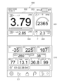
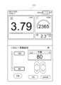
- FIG. 3 is a schematic explanatory diagram showing a "first screen 200".
- a first screen example 200 has a first display area, for example an upper display 201, and a second display area, for example a lower display 210.
- the upper display 201 On the upper display 201, for example, three frames for displaying information are arranged, specifically, as shown in FIG. 3, a large frame, a medium frame, and a small frame. Furthermore, the upper display 201 displays fixed information that is particularly important to the extracorporeal circulation apparatus 1, such as the "flow rate value,” the "rotation speed of the centrifugal pump,” and the "FI value.”
- This large frame is a "flow rate frame 202" in which numerical information on the flow rate (blood flow rate (L/min)/body surface area (m2)) is displayed, for example.
- the flow rate value is displayed in the "flow rate frame 202" by referring to the value of the flow rate sensor in the extracorporeal circulation information storage unit 117, and the current value, for example "3.79 (an example of numerical information)".
- Flow rate is displayed in a "large box” because it is an important indicator for understanding the amount of blood circulating. Specifically, medical personnel check that the flow rate is a constant value as an index of circulation, and a low flow rate indicates insufficient blood circulation.
- the medium frame is a "centrifugal pump frame 203" in which numerical information on the rotation speed of the centrifugal pump 3 (revolutions per minute of the centrifugal pump) is displayed, for example.
- the rotation speed of the centrifugal pump is determined by referring to the value of the centrifugal pump 3 in the extracorporeal circulation information storage unit 117, and in the case of FIG. 3, the current value "2365" is displayed.
- the rotation speed of the centrifugal pump 3 is related to the flow rate, and is an important index to be viewed together with the flow rate when a problem occurs, so it is displayed.
- the centrifugal pump frame 203 simultaneously displays the letters "RPM” indicating the rotation speed of the centrifugal pump 3 and a "centrifugal pump icon R" together with numerical information.
- the smaller frame is an "FI frame 204" in which numerical information such as FI (Flow Index: L/min/m2) is displayed.
- FI value (L/min/m2) refers to the FI value in the extracorporeal circulation information storage unit 117, and the current value "2.3” is displayed.
- FI is similar to the cardiac index (CI), but differs from CI in that CI indicates the circulatory state within the patient's body, whereas FI determines the amount of blood in the extracorporeal circulation device 1.
- FI is an index for grasping hemodynamics, and is an index obtained by correcting and converting the amount of blood circulation according to the patient's body size (per body surface area).
- FI is one of the indices for confirming an appropriate state of blood circulation.
- FI frame 204" as shown in FIG. 3, an "FI icon F" is simultaneously displayed together with the numerical information of FI.
- the "lower display 210" is provided with a plurality of screens, for example, two types of screens, and the user can switch between the screens by operating the "screen change icon C1" in FIG. Specifically, this is the “lower display 210" of the "first screen 200" in FIG. 3 and the “lower display 310" of the second screen 300 in FIG. 4, which will be described later, each of which will be described below.
- Figure 3 shows the "lower display 210" of the "first screen 200", and specifically, it displays current numerical information such as the pressure values of the first pressure sensor P1 (delivery pressure), the second pressure sensor P2 (artificial lung pressure), and the third pressure sensor P3 (delivery pressure), the oxygen saturation value of the oxygen saturation sensor 21, the temperature value of the temperature sensor 23, the value of the hematocrit sensor 22, the value of the hemoglobin meter 24, which is non-fixed information related to fixed information such as the flow rate value, the rotation speed of the centrifugal pump, and the FI value displayed on the upper display 201.
- the pressure values of the first pressure sensor P1 delivery pressure
- the second pressure sensor P2 artificial lung pressure
- P3 delivery pressure
- the oxygen saturation value of the oxygen saturation sensor 21 the temperature value of the temperature sensor 23
- the value of the hematocrit sensor 22 the value of the hemoglobin meter 24 which is non-fixed information related to fixed information such as the flow rate value, the rotation speed of the centrifugal pump, and the FI
- all extracorporeal circulation information is displayed as current numerical values, making it an effective screen when the user wants to grasp the patient's current extracorporeal circulation information as numerical information.
- first pressure sensor P1 delivery pressure
- second pressure sensor P2 artificial lung pressure
- third pressure sensor P3 feed pressure
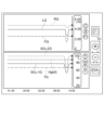
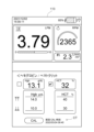
- FIG. 4 is a schematic diagram showing the second screen 300.
- the upper display 201 of the second screen 300 is similar to the first screen 200 of FIG. 3, and therefore is given the same reference numeral and description thereof will be omitted.
- the lower display 310 displays trend graph information of the flow rate value, etc. displayed on the upper display 201, as well as trend graph information of the first pressure sensor P1, etc., which is related to the flow rate value, etc., which is fixed information.
- the lower display 310 further includes an "upper lower display 311" and a “lower lower display 312", each of which is configured to display trend graph information of extracorporeal circulation information.
- the trend graph information of extracorporeal circulation information is a graph showing the transition of extracorporeal circulation information within a predetermined time, such as the flow rate value of a flow sensor, the rotation speed of a centrifugal pump, the FI value, etc.
- the “trend graph generating unit (program) 116” in FIG. 2 operates to generate a trend graph of flow rate values, etc. based on information such as flow rate values in the extracorporeal circulation information storage unit 117, and display it on the lower display 310.
- the extracorporeal circulation information generated as a trend graph includes, in addition to flow rate values, the pressure values of the first pressure sensor P1, the second pressure sensor P2, and the third pressure sensor P3, the oxygen saturation value of the oxygen saturation sensor 21, the temperature value of the temperature sensor 23, the value of the hematocrit sensor 22, the value of the hemoglobin meter 24, etc.
- the main reasons for displaying such a trend graph on the display 113 are as follows.
- the operator does not constantly monitor the patient while the patient is in a stable state, but performs periodic monitoring. For this reason, a "trend graph" is displayed to allow the operator (user) to ascertain the time periods during which monitoring is not possible.
- the progress before the alarm occurred can be confirmed by visually checking the trend graph.
- the "upper-lower display 311" of the “lower display 310" of the second screen 300 displays the flow rate value of the flow sensor 7, the rotation speed of the centrifugal pump 3, the FI value, etc., which are displayed on the upper display 201, as shown in FIG.
- the upper lower display 311 displays trend graphs for the same values as the flow rate value, the centrifugal pump rotation speed value, and the FI value displayed on the upper display 201 .
- these are a "flow rate trend graph LG,” a "revolutions per minute trend graph RG of the centrifugal pump 3,” and an "FI value trend graph FG.”
- the upper display 201 displays current numerical values such as flow rate values
- the upper lower display 311 displays trend graphs LG for a specified time period for values corresponding to the upper display 201, allowing the flow rate values, etc. to be grasped more accurately.
- a user viewing a trend graph can instantly understand the type of the trend graph by visually checking the icon displayed nearby.
- the "flow rate icon L1" etc. are arranged so as not to overlap each other, and even if the displayed trend graph LG etc. intersects along the way, the "flow rate icon L1" etc. are arranged according to a position corresponding to the current value of the trend graph LG, making them easy for the user to see.
- the user can instantly determine which trend graph LG, etc. each trend graph LG, etc. corresponds to.
- the "graph scale M" of the trend graph LG etc. is also displayed in parallel and close to the current value side of the trend graph LG etc.
- the most important information for the extracorporeal circulation device 1 namely, the current numerical values of the "flow rate value,”"centrifugal pump RPM value,” and "FI value,” are displayed on the upper display 201, and the upper lower display 321 of the lower display 320 displays trend graphs LG of the same "flow rate value,” etc., thereby enabling the user to reliably check the most important information.
- the lower display 312 on the lower side of FIG. 4 displays a trend graph based on the values of the "first pressure sensor P1", “second pressure sensor P2" and “third pressure sensor P3". Specifically, as shown in FIG. 4, they are a “first pressure sensor trend graph P1G,” a “second pressure sensor trend graph P2G,” and a “third pressure sensor trend graph P3G.”
- a "first pressure sensor icon P1I”, a “second pressure sensor icon P2I” and a “third pressure sensor icon P3I” are arranged in parallel and close to each other.
- the “graph scale M” of the trend graph is also displayed in parallel and close to it.
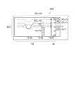
- FIG. 5 is a schematic diagram showing an example of a screen of the lower display 422 on the lower side of the third screen 400. As shown in FIG. The user can change (transition) the screen from the second screen 300 in FIG. 4 to the third screen 400 in FIG. 5 by operating a screen change icon C2, for example.
- FIG. 5 displays a trend graph based on the "oxygen saturation value of oxygen saturation sensor 21,”"temperature value of temperature sensor 23," and “value of hematocrit sensor 22.” Specifically, as shown in FIG. 5, these are “oxygen saturation sensor trend graphs SO2-1G, SO2-2G,””temperature trend graph TG,” and “hematocrit trend graph HCTG.”
- an “oxygen saturation sensor icon (SO2-1I) (SO2-2I),” a “temperature sensor icon (TI),” and a “hematocrit icon (HCTI)” are displayed in parallel and close to each other.
- the “graph scale M" of the trend graphs SO2-1 etc. is also displayed in parallel and adjacent thereto.
- the trend graph is easily visible to the user.
- the upper display 201 displays the “current value” of the most important parameter
- the upper-lower display 311 of the lower display 310 displays a trend graph LG of the parameter displayed on the upper display 201
- the lower-lower displays 312, 422 change the display of the parameters to be checked to two screens as necessary, thereby making it easy for the user to check the parameters.
- trend graphs LG, etc. displayed on the lower display 320 are all trend graphs LG, etc. for the same time period (TS), so it is easy to know whether the extracorporeal circulation device 1 is operating normally, etc.
- FIGS. 6 and 7 are schematic explanatory diagrams showing a “fourth screen 500 ” that displays information about the optional flow sensor 17 on the display 113 . That is, in Figure 6, unlike Figure 3, the upper display 501 displays an "optional flow rate frame 503" that displays the flow rate value of the optional flow sensor 17 (e.g., 2.85) below a flow rate frame 502 that displays the flow rate value of the flow sensor 7.
- the optional flow rate frame 503 displays the flow rate value of the optional flow sensor 17 (e.g., 2.85) below a flow rate frame 502 that displays the flow rate value of the flow sensor 7.
- This optional flow rate sensor 17 is a flow rate sensor that is optionally installed in the extracorporeal circulation apparatus 1 of FIG. Therefore, when a user of the extracorporeal circulation device 1 sets this optional flow sensor 17 to be used (enabled), the first screen 200 in Figure 3, which is displayed when the optional flow sensor 17 is not in use, is switched to the fourth screen 500 in Figure 6, and an "optional flow frame 503" is displayed. At this time, the “optional flow rate frame 503 ” is displayed smaller than the “flow rate frame 502 ” that displays the flow rate value of the flow sensor 7 . Therefore, the configuration is such that it is possible to prevent a situation in which the presence of the "optional flow rate frame 503" makes it difficult for the user to visually recognize the flow rate value of the flow rate sensor 7.
- the letters "LPM” indicating the flow rate of the optional flow rate sensor 17 and the "optional flow rate icon L2" are displayed together with numerical information (e.g., 2.85).
- the screen change icon C1 when the screen change icon C1 is selected while the fourth screen 500 in FIG. 6 is being displayed, the screen transitions to the screen in FIG. 7, the display transitions from the lower display 210 in FIG. 6 to the lower display 510 in FIG.
- the lower display 510 in FIG. 7 displays trend graph information such as flow rate values.
- the upper-lower display 511 not only displays the "flow rate trend graph LG,””rotation speed trend graph RG of the centrifugal pump 3," and “FI value trend graph FG,” but also, unlike the first screen 200 of FIG. 3, the "optional flow rate trend graph OLG,” which is a trend graph of the optional flow sensor 17. Furthermore, an “optional flow rate icon L2" is displayed adjacent to the current value side of this "optional flow rate trend graph OLG".
- users of the optional flow sensor 17 can easily grasp not only the numerical information but also the trend graph OLG information with simple operations.
- extracorporeal circulation information (flow rate, etc.) is displayed on the display 113 so that the user can understand or easily understand it, and by selecting a screen change icon C1, etc. shown in Figure 3, the screen can be changed (transitioned) to Figure 3, 4, 5, etc., as necessary.
- the display 113 is small, the user can quickly and reliably grasp the necessary information.
- the extracorporeal circulation device 1 which requires skill, there are cases where the numerical values and the like that should be visually confirmed first cannot be easily recognized.
- this is particularly required in situations where the extracorporeal circulation apparatus 1 is used in a highly urgent manner.
- by appropriately changing the screen of the display 113 even a less skilled person can easily and quickly recognize the numerical values and the like that should be visually recognized first.
- non-fixed information As described above, according to this embodiment, multiple types of non-fixed information (numerical screens, trend graphs, etc.) are switched and displayed in sequence on the lower display 210, etc., so the user can easily and quickly grasp all of this non-fixed information at an easily visible size.
- the screens in FIG. 3 to FIG. 7 can be changed by the user's operation or the like, but the following configuration is also provided. That is, when a certain period of time has elapsed without the user performing any operation, the screens of FIG. 3, FIG. 4, and FIG. 5 are automatically changed and displayed in a predetermined order.
- the present invention is not limited to this, and the contents of the lower display 210 are automatically changed and displayed in a predetermined order after a predetermined time has passed.
- the minimum time is set to 3 seconds, which is the time that a user can recognize when intentionally checking the screen, and since there is a need to see both screens for the purpose of switching between displays, the maximum display time can be set to 10 seconds. Moreover, the user can set within this range.
- the device Since it would be difficult for a user to operate the device if the screen were to change automatically while the user was operating it, the device is designed so that if the user stops operating the device and leaves it for a certain period of time (for example, one minute), a function to automatically switch the display will start operating. In addition, when you touch the screen and start operating it, the display switching function is stopped.
- These functions allow users to check the current status numerically and the trend from the past to the present in graphs without the need for manual operation, even when they cannot take their hands off the device or do not want to perform unnecessary operations during regular patient rounds. The advantage is that you can grasp both types of information without manual operation.
- the display time of the trend graph LG etc. is three hours (11:00 to 14:00) on the second screen 300 of the display 113 in FIG. 4 and the third screen 400 in FIG.
- the time axis which is the display time of the trend graph LG, etc., is freely changeable by the user. Specifically, the time axis on the screen can be changed by selecting the "time axis icon TC" of "time axis +" and "time axis -" displayed on the right side of the lower display 310 in FIG.
- FIG. 8 is a schematic explanatory diagram showing an example of a screen in which the time axis has been changed to 24 hours.
- FIG. 9 is a schematic explanatory diagram showing an example of a screen in which the time axis has been changed to 12 hours.
- the time axis in FIG. 8 when the time axis in FIG. 8 is in the 12-hour state and one wishes to display past data that is not currently displayed on the screen, one can select the past time axis icon PC in FIG. 9 to display data on the time axis for the desired time period, for example, from 14:00 to 02:00.
- the user can display trend graph information on the time axis required each time, resulting in an easy-to-use configuration.
- the numerical settings (upper limit values for alarms, etc.) set for each extracorporeal circulation information displayed on the display 113 can be changed in a simple manner, as will be described below.
- this embodiment will explain the example of changing the settings of non-fixed information (extracorporeal circulation information other than flow rate value, centrifugal pump rotation speed, and FI value), such as pressure value, oxygen saturation, hematocrit value, and other alarms.
- FIG. 10 is an example of a pressure setting screen.
- a "Pressure warning setting screen” opens as shown in FIG.
- FIG. 11 is a schematic diagram showing a pressure warning setting screen.
- the upper limit setting value (900 mmHg) can be changed.
- the pressure value of the pressure warning setting can be changed and registered easily and quickly by simply selecting the relevant portion of the screen.
- FIG. 12 is an example of an oxygen saturation alarm setting screen.
- FIG. 13 is a schematic diagram showing the SO2-1 alarm setting screen.
- the lower limit setting value (80%) can be changed.
- the oxygen saturation setting can be changed and registered easily and quickly by simply selecting the relevant portion of the screen.
- FIG. 14 is an example of a screen showing a hemoglobin/hematocrit value setting screen.
- FIG. 15 is a schematic diagram showing a hematocrit value setting screen.
- the lower limit setting value (30%) can be changed. In this manner, in this embodiment, the hematocrit value can be changed and registered easily and quickly by simply selecting the relevant portion on the screen.
- a time display has a problem in that even if a user visually checks the time display, the user cannot instantly grasp the elapsed time since the previous CAL. Therefore, in this embodiment, a display such as "the last calibration time was 10 hours ago" can be displayed, making it possible to display information about the elapsed time starting from the current time.
- FIG. 16 is a schematic explanatory diagram showing a display of the elapsed time during CAL.
- the management device 10 stores data for "displaying the elapsed time since the previous calibration" shown in FIG. Then, when the user displays the setting change screen shown in FIG. 14 in order to change the hemoglobin/hematocrit value setting, the screen example shown on the left side of FIG. 16 appears instead of the screen shown in FIG.
- the time from the present until the previous calibration is performed is displayed instead of the time when the calibration is performed. Specifically, it is determined based on which item in the table of FIG. 16 corresponds to the time when the previous CAL was performed and the time up to the present (set time). For example, if the time from the last CAL to the present is "90 minutes,”"1 hour ago" is displayed.
- the hemoglobin/hematocrit setting change screen allows you to instantly grasp the approximate time that has elapsed since the previous CAL.
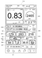
- FIG. 17 is a schematic explanatory diagram showing the display 113 in a state in which a warning is displayed.
- an "abnormal value information detection unit (program) 120" that detects abnormal value information regarding the "flow rate value,”"centrifugal pump rotation speed,” and “FI value” on the "upper display 201" shown in FIG. 17, and the "first pressure sensor value P1,""second pressure sensor value P2,””third pressure sensor value P3,””oxygen saturation sensor values SO2-1, S02-2,””hemoglobin value Hgb,” and "temperature value T” displayed on the "lower display 210" (FIG. 2).
- the flow rate value and the like on the upper display 201 are displayed surrounded by frames 202, 203, and 204, respectively.
- the “first pressure sensor value P1,” “second pressure sensor value P2,” “third pressure sensor value P3,” “oxygen saturation sensor value SO2-1,” “oxygen saturation sensor S02-2,” “hemoglobin value Hgb,” and “temperature value T” on the lower display 210 are each displayed surrounded by frames 221 to 229 as shown in FIG. 17.
- the frame in which the abnormality occurred is shown as an abnormal frame in an alarm color that is different from the background color of the display 113.
- This alarm color is shown in different colors depending on the priority of the alarm. In Figure 17, if the alarm level is high, it is shown in red (right-sloping hatching), and if the level is low, it is shown in yellow (left-sloping hatching).
- the frame 202 for "Flow rate value” on the upper display 201 and the frames 221, 222 for "First pressure sensor value P1" and “Second pressure sensor value P2" on the lower display 210 are displayed in the warning color of red (right-slanting hatching). Additionally, frames 226, 227, 229, etc., for "oxygen saturation sensor value SO2-1,””oxygen saturation sensor S02-2,””hemoglobin value Hgb,” etc. on the lower display 210 are displayed in a yellow warning color.
- the user can instantly grasp whether or not a warning has occurred and its severity. It is also possible to induce the user to click (check) on a part with a high priority.
- an abnormality is indicated in red or yellow, and an icon showing the content of the abnormality, for example, an "alarm content icon AA", is also displayed. Specifically, when the abnormal value exceeds the upper limit, an upward arrow is displayed, and when the abnormal value exceeds the lower limit, a downward arrow is displayed.
- an "alarm content icon AA" with an upward arrow is displayed in the flow rate frame 202, the frame 222 of the "second pressure sensor value P2", the frame 226 of the “oxygen saturation sensor value SO2-1”, etc. Additionally, a downward arrow “alarm content icon AA” is displayed in frames 221, 227, 229, etc. of "first pressure sensor value P1", “hemoglobin value Hgb”, and "oxygen saturation level S02-2".
- abnormality information display section (abnormality information content), for example, “abnormality content text information 230 (for example, “B1 air bubble detected” alarm, “coast rotation + air bubble” alarm, etc.)” is scroll-displayed.
- the number of abnormal values (number information) 231 (for example, 2 red and 0 yellow in FIG. 17) is also displayed.
- the "number of abnormal values 231" displayed on the display 113 also includes other hidden abnormal values for which no warning is actually displayed in red or yellow. The user can grasp the specifics of the abnormality and also the exact number of abnormalities. In addition, the number of abnormal value information items can be accurately grasped according to their level.
- FIG. 18 is a schematic diagram showing an example of three pieces of abnormality content text information displayed on the display 113
- FIG. 18(1) is a schematic diagram showing an example of displaying two of the three pieces of abnormality content text information, "B1 air bubble detected (red warning color)” and “Coast rotation + air bubble (red warning color).”
- FIG. 18(2) is a schematic diagram showing an example of displaying "coast rotation + bubbles (red warning color)” and "low SO2-1 (yellow warning color)", which correspond to two of the three.
- the "abnormality content text information 230" is configured to be able to display up to two items, and is therefore displayed on the display 113 as follows. Furthermore, the multiple pieces of "anomaly content text information 230" are configured to be displayed in order from top to bottom, for example, in descending order of priority of the alarm occurrence.
- the top row displays "B1 air bubble detection (red alarm color),” which is a high-priority alarm that should be resolved first, and the bottom row displays “coast rotation + air bubble (red alarm color),” which is the next highest priority alarm.
- the third highest priority alarm “Low SO2-1 (yellow alarm color)” cannot be displayed at the same time.
- a strip-shaped zone Z1 is placed below the "Coast rotation + air bubbles (red warning color)" displayed in the second lower row, as shown in Figure 18 (1). In this zone Z1, it is not possible to display “Low SO2-1 (yellow warning color)", but instead, no text or other characters are displayed and only the warning color (yellow) is displayed.
- the user can know that an alarm with the third highest priority has also occurred, and can instantly know the severity of the alarm (red or yellow).
- the number of abnormal values 231 is displayed in different colors (by level of warning) in the same manner as in FIG. 17, so that the user can instantly grasp the level of the warning and the number of abnormal values.
- FIG. 18(2) is a schematic explanatory diagram showing the state in which the display of the "abnormality content text information 230" in FIG. 18(1) is scrolled.
- the top row displays "Coast rotation + bubbles (red warning color)" which was the bottom row in (1)
- the bottom row displays "Low SO2-1 (yellow warning color)” which was displayed in zone Z1 in (1).
- the top row displays "Coast rotation + bubbles (red warning color)" which was the bottom row in (1)
- the bottom row displays "Low SO2-1 (yellow warning color)” which was displayed in zone Z1 in (1).
- a strip-shaped zone Z2 is placed above "coast rotation + air bubble (red warning color)” in the upper row, and only the warning color (red) is displayed without displaying any text or the like.
- the user can know that an alarm has occurred first in the order of priority, and can also instantly know the severity of the alarm (red or yellow).
- FIG. 19 is a schematic diagram showing an example in which four pieces of anomaly content text information are displayed on the display 113, and (1) to (3) are schematic diagrams showing the scroll display.
- four warnings have occurred. Specifically, in order of occurrence time, the following warnings have occurred: That is, the alarms occur in the following order: "B1 air bubble detection (red alarm color)” ⁇ "coast rotation + air bubbles (red alarm color)” ⁇ "low SO2-1 (yellow alarm)” ⁇ "P1 high pressure (red alarm color)".
- the alarms are converted and displayed in order of increasing priority, rather than in the order of occurrence, that is, in the order of "B1 air bubble detection (red alarm color)"->"P1 high pressure (red alarm color)"->"coast rotation + air bubbles (red alarm color)"->"low SO2-1 (yellow alarm).”
- the scrolling display is as follows, which will be described below with reference to (1) to (3) in FIG.
- the highest priority alarm "B1 air bubble detection (red alarm color),” is displayed in the upper row, and the next highest priority alarm, “P1 high pressure (red alarm color),” is displayed in the lower row.
- the third highest priority alarm “Coast rotation + bubbles (red alarm color),” is shown in a band-shaped zone Z3 that displays only the alarm color (red), while the fourth highest priority alarm, "Low SO2-1 (yellow alarm),” is not displayed.
- the number of abnormal values 231 in Figure 19 (1) indicates that there are three red values and one yellow value, so the user can understand that a total of four alerts have occurred and the severity of the alerts (three red values and one yellow value).
- the user can easily check all the alarms by scrolling the "abnormality content text information 230" displayed on the display 113.
- strip-shaped zone Z1 or the like is displayed above or below an alarm that displays text or the like, but the present invention is not limited to this, and multiple strip-shaped zones Z1 or the like may be arranged.
- the invention is realized as a device, but the invention is not limited to this, and the invention may be distributed as a program that can be executed by a computer, stored on a storage medium such as a magnetic disk (floppy disk, hard disk, etc.), an optical disk (CD-ROM, DVD, etc.), a magneto-optical disk (MO), or a semiconductor memory.
- a storage medium such as a magnetic disk (floppy disk, hard disk, etc.), an optical disk (CD-ROM, DVD, etc.), a magneto-optical disk (MO), or a semiconductor memory.
- the storage medium may be any medium that can store a program and is computer readable. There are no particular limitations on the storage format of the storage medium.
- an OS operating system
- database management software network software
- MW middleware
- the storage medium in this invention is not limited to media independent of a computer, but also includes storage media that stores or temporarily stores downloaded programs transmitted via a LAN, the Internet, etc.
- the computer of the present invention only needs to execute each process in this embodiment based on a program stored in a storage medium, and may be a device consisting of a single personal computer, or a system in which multiple devices are connected to a network.
- the computer in this invention is not limited to a personal computer, but also includes an arithmetic processing device included in information processing equipment, a microcomputer, and an artificial lung, and is a general term for equipment and devices that can realize the functions of this invention by a program.
Landscapes
- Health & Medical Sciences (AREA)
- Heart & Thoracic Surgery (AREA)
- Vascular Medicine (AREA)
- Engineering & Computer Science (AREA)
- General Health & Medical Sciences (AREA)
- Public Health (AREA)
- Biomedical Technology (AREA)
- Cardiology (AREA)
- Anesthesiology (AREA)
- Animal Behavior & Ethology (AREA)
- Hematology (AREA)
- Veterinary Medicine (AREA)
- Life Sciences & Earth Sciences (AREA)
- Urology & Nephrology (AREA)
- Pulmonology (AREA)
- Medical Informatics (AREA)
- Epidemiology (AREA)
- Primary Health Care (AREA)
- Surgery (AREA)
- Nuclear Medicine, Radiotherapy & Molecular Imaging (AREA)
- Emergency Medicine (AREA)
- Business, Economics & Management (AREA)
- General Business, Economics & Management (AREA)
- External Artificial Organs (AREA)
Priority Applications (2)
| Application Number | Priority Date | Filing Date | Title |
|---|---|---|---|
| JP2025510177A JPWO2024203127A1 (https=) | 2023-03-24 | 2024-03-07 | |
| US19/336,598 US20260014305A1 (en) | 2023-03-24 | 2025-09-23 | Extracorporeal circulation device, including management device, and method of operation |
Applications Claiming Priority (2)
| Application Number | Priority Date | Filing Date | Title |
|---|---|---|---|
| JP2023-048918 | 2023-03-24 | ||
| JP2023048918 | 2023-03-24 |
Related Child Applications (1)
| Application Number | Title | Priority Date | Filing Date |
|---|---|---|---|
| US19/336,598 Continuation US20260014305A1 (en) | 2023-03-24 | 2025-09-23 | Extracorporeal circulation device, including management device, and method of operation |
Publications (1)
| Publication Number | Publication Date |
|---|---|
| WO2024203127A1 true WO2024203127A1 (ja) | 2024-10-03 |
Family
ID=92905642
Family Applications (1)
| Application Number | Title | Priority Date | Filing Date |
|---|---|---|---|
| PCT/JP2024/008829 Ceased WO2024203127A1 (ja) | 2023-03-24 | 2024-03-07 | 管理装置、管理装置を有する体外循環管理装置、管理装置の作動方法及び管理装置の作動プログラム |
Country Status (3)
| Country | Link |
|---|---|
| US (1) | US20260014305A1 (https=) |
| JP (1) | JPWO2024203127A1 (https=) |
| WO (1) | WO2024203127A1 (https=) |
Citations (4)
| Publication number | Priority date | Publication date | Assignee | Title |
|---|---|---|---|---|
| JPH10234849A (ja) * | 1997-02-28 | 1998-09-08 | Terumo Corp | 腹膜透析装置 |
| JP2008220396A (ja) * | 2007-03-08 | 2008-09-25 | Toshiba Corp | 医用診断装置 |
| JP2018529503A (ja) * | 2015-10-07 | 2018-10-11 | マクエット カルディオプルモナリー ゲーエムベーハー | ユーザインターフェース |
| JP2022514531A (ja) * | 2018-12-19 | 2022-02-14 | リヴァノヴァ・ドイチュラント・ゲーエムベーハー | 制御装置を有する人工心肺 |
-
2024
- 2024-03-07 JP JP2025510177A patent/JPWO2024203127A1/ja active Pending
- 2024-03-07 WO PCT/JP2024/008829 patent/WO2024203127A1/ja not_active Ceased
-
2025
- 2025-09-23 US US19/336,598 patent/US20260014305A1/en active Pending
Patent Citations (4)
| Publication number | Priority date | Publication date | Assignee | Title |
|---|---|---|---|---|
| JPH10234849A (ja) * | 1997-02-28 | 1998-09-08 | Terumo Corp | 腹膜透析装置 |
| JP2008220396A (ja) * | 2007-03-08 | 2008-09-25 | Toshiba Corp | 医用診断装置 |
| JP2018529503A (ja) * | 2015-10-07 | 2018-10-11 | マクエット カルディオプルモナリー ゲーエムベーハー | ユーザインターフェース |
| JP2022514531A (ja) * | 2018-12-19 | 2022-02-14 | リヴァノヴァ・ドイチュラント・ゲーエムベーハー | 制御装置を有する人工心肺 |
Also Published As
| Publication number | Publication date |
|---|---|
| US20260014305A1 (en) | 2026-01-15 |
| JPWO2024203127A1 (https=) | 2024-10-03 |
Similar Documents
| Publication | Publication Date | Title |
|---|---|---|
| JP7076420B2 (ja) | ユーザインターフェース | |
| US8936555B2 (en) | Real time clinical decision support system having linked references | |
| US10636523B2 (en) | Device, system and method for visualization of patient-related data | |
| JP5961626B2 (ja) | アラーム装置のアラームリミットを制御する装置 | |
| US20130245481A1 (en) | Real time clinical decision support system having medical systems as display elements | |
| CN103565418B (zh) | 用于监视对象的临床状态的方法、设备 | |
| JP2004243126A (ja) | 患者医療パラメータユーザインターフェースシステム | |
| EP2368491B1 (en) | Method and device for determining an indicator of generator clinical state | |
| JP6310467B2 (ja) | 表示装置及び表示方法 | |
| US10136813B2 (en) | Systems and methods for patient cardiovascular and respiratory management | |
| US11446438B2 (en) | Systems and methods for patient cardiovascular and respiratory management | |
| US9265903B2 (en) | Ventilation vitality ring | |
| US20250128050A1 (en) | Visual indicator associated with a medical device | |
| US20260069149A1 (en) | Systems and methods for patient cardiovascular and respiratory management | |
| WO2024203127A1 (ja) | 管理装置、管理装置を有する体外循環管理装置、管理装置の作動方法及び管理装置の作動プログラム | |
| KR20250110254A (ko) | 혈역학적 신호 또는 지표의 보조 디스플레이를 위한 시스템 및 방법 | |
| CN114376512B (zh) | 一种报警处理方法、中央显示设备、监测或治疗的设备 | |
| JP2024137406A (ja) | 管理装置、管理装置を有する体外循環管理装置、管理装置の作動方法及び管理装置の作動プログラム | |
| WO2023006116A1 (zh) | 监护设备和用于目标对象的显示方法 | |
| JP2024137408A (ja) | 管理装置、管理装置を有する体外循環管理装置、管理装置の作動方法及び管理装置の作動プログラム | |
| JP2024137407A (ja) | 管理装置、管理装置を有する体外循環管理装置、管理装置の作動方法及び管理装置の作動プログラム | |
| WO2014182682A1 (en) | Real time clinical decision support system having linked references | |
| WO2026053945A1 (ja) | 管理装置、管理装置を有する体外循環管理装置、管理装置の作動方法及び管理装置の作動プログラム |
Legal Events
| Date | Code | Title | Description |
|---|---|---|---|
| 121 | Ep: the epo has been informed by wipo that ep was designated in this application |
Ref document number: 24779261 Country of ref document: EP Kind code of ref document: A1 |
|
| WWE | Wipo information: entry into national phase |
Ref document number: 2025510177 Country of ref document: JP |
|
| NENP | Non-entry into the national phase |
Ref country code: DE |
|
| 122 | Ep: pct application non-entry in european phase |
Ref document number: 24779261 Country of ref document: EP Kind code of ref document: A1 |