WO2024202685A1 - 自動工具交換装置付き工作機械及びそれに用いられる渦電流センサ - Google Patents
自動工具交換装置付き工作機械及びそれに用いられる渦電流センサ Download PDFInfo
- Publication number
- WO2024202685A1 WO2024202685A1 PCT/JP2024/005678 JP2024005678W WO2024202685A1 WO 2024202685 A1 WO2024202685 A1 WO 2024202685A1 JP 2024005678 W JP2024005678 W JP 2024005678W WO 2024202685 A1 WO2024202685 A1 WO 2024202685A1
- Authority
- WO
- WIPO (PCT)
- Prior art keywords
- length
- coil
- core
- tool
- eddy current
- Prior art date
- Legal status (The legal status is an assumption and is not a legal conclusion. Google has not performed a legal analysis and makes no representation as to the accuracy of the status listed.)
- Ceased
Links
Images


Classifications
-
- B—PERFORMING OPERATIONS; TRANSPORTING
- B23—MACHINE TOOLS; METAL-WORKING NOT OTHERWISE PROVIDED FOR
- B23Q—DETAILS, COMPONENTS, OR ACCESSORIES FOR MACHINE TOOLS, e.g. ARRANGEMENTS FOR COPYING OR CONTROLLING; MACHINE TOOLS IN GENERAL CHARACTERISED BY THE CONSTRUCTION OF PARTICULAR DETAILS OR COMPONENTS; COMBINATIONS OR ASSOCIATIONS OF METAL-WORKING MACHINES, NOT DIRECTED TO A PARTICULAR RESULT
- B23Q17/00—Arrangements for observing, indicating or measuring on machine tools
- B23Q17/002—Arrangements for observing, indicating or measuring on machine tools for indicating or measuring the holding action of work or tool holders
- B23Q17/003—Arrangements for observing, indicating or measuring on machine tools for indicating or measuring the holding action of work or tool holders by measuring a position
-
- G—PHYSICS
- G01—MEASURING; TESTING
- G01B—MEASURING LENGTH, THICKNESS OR SIMILAR LINEAR DIMENSIONS; MEASURING ANGLES; MEASURING AREAS; MEASURING IRREGULARITIES OF SURFACES OR CONTOURS
- G01B7/00—Measuring arrangements characterised by the use of electric or magnetic techniques
- G01B7/14—Measuring arrangements characterised by the use of electric or magnetic techniques for measuring distance or clearance between spaced objects or spaced apertures
-
- G—PHYSICS
- G01—MEASURING; TESTING
- G01B—MEASURING LENGTH, THICKNESS OR SIMILAR LINEAR DIMENSIONS; MEASURING ANGLES; MEASURING AREAS; MEASURING IRREGULARITIES OF SURFACES OR CONTOURS
- G01B7/00—Measuring arrangements characterised by the use of electric or magnetic techniques
- G01B7/30—Measuring arrangements characterised by the use of electric or magnetic techniques for measuring angles or tapers; for testing the alignment of axes
- G01B7/31—Measuring arrangements characterised by the use of electric or magnetic techniques for measuring angles or tapers; for testing the alignment of axes for testing the alignment of axes
-
- G—PHYSICS
- G01—MEASURING; TESTING
- G01N—INVESTIGATING OR ANALYSING MATERIALS BY DETERMINING THEIR CHEMICAL OR PHYSICAL PROPERTIES
- G01N27/00—Investigating or analysing materials by the use of electric, electrochemical, or magnetic means
- G01N27/72—Investigating or analysing materials by the use of electric, electrochemical, or magnetic means by investigating magnetic variables
- G01N27/82—Investigating or analysing materials by the use of electric, electrochemical, or magnetic means by investigating magnetic variables for investigating the presence of flaws
- G01N27/90—Investigating or analysing materials by the use of electric, electrochemical, or magnetic means by investigating magnetic variables for investigating the presence of flaws using eddy currents
- G01N27/9006—Details, e.g. in the structure or functioning of sensors
-
- B—PERFORMING OPERATIONS; TRANSPORTING
- B23—MACHINE TOOLS; METAL-WORKING NOT OTHERWISE PROVIDED FOR
- B23Q—DETAILS, COMPONENTS, OR ACCESSORIES FOR MACHINE TOOLS, e.g. ARRANGEMENTS FOR COPYING OR CONTROLLING; MACHINE TOOLS IN GENERAL CHARACTERISED BY THE CONSTRUCTION OF PARTICULAR DETAILS OR COMPONENTS; COMBINATIONS OR ASSOCIATIONS OF METAL-WORKING MACHINES, NOT DIRECTED TO A PARTICULAR RESULT
- B23Q17/00—Arrangements for observing, indicating or measuring on machine tools
- B23Q2017/001—Measurement or correction of run-out or eccentricity
-
- B—PERFORMING OPERATIONS; TRANSPORTING
- B23—MACHINE TOOLS; METAL-WORKING NOT OTHERWISE PROVIDED FOR
- B23Q—DETAILS, COMPONENTS, OR ACCESSORIES FOR MACHINE TOOLS, e.g. ARRANGEMENTS FOR COPYING OR CONTROLLING; MACHINE TOOLS IN GENERAL CHARACTERISED BY THE CONSTRUCTION OF PARTICULAR DETAILS OR COMPONENTS; COMBINATIONS OR ASSOCIATIONS OF METAL-WORKING MACHINES, NOT DIRECTED TO A PARTICULAR RESULT
- B23Q3/00—Devices holding, supporting, or positioning work or tools, of a kind normally removable from the machine
- B23Q3/155—Arrangements for automatic insertion or removal of tools, e.g. combined with manual handling
Definitions
- the present invention relates to an automatically controlled machine tool, such as an NC (numerically controlled) processing machine or machining center, which performs automatic control to process a workpiece (object to be processed, object to be measured), and is particularly suitable for a machine tool with an automatic tool changer (ATC) that selects and attaches/detaches machining tools as appropriate, and which automatically measures the shape of a workpiece during processing of the object to be processed or when a certain processing step has been completed, and an eddy current sensor used therein.
- NC number of controlled processing machine or machining center
- NC machines and machining centers are devices that automatically select various tools according to the machining process and automatically attach them to the spindle to perform a wide variety of machining operations. They are equipped with a machining table on which the workpiece is placed and fixed, a spindle head that drives the attached machining tools attached to the tool spindle at a position that passes through the tool spindle where the tools are attached, and an automatic tool changer (ATC device) that appropriately selects and attaches/detaches the attached tools attached to the spindle head.
- ATC device automatic tool changer
- Tools are changed using an automatic tool change (ATC) device.
- ATC device automatically removes the tool holder with the tool attached from the tool magazine and automatically attaches it to the spindle (tool change operation).
- Tools are attached to the tool holder, whose size, shape, etc. are determined by predetermined standards so that they can be attached and detached by the ATC device.
- Automatic tool changers are expected to speed up tool change operations in order to reduce the cost of processed products and shorten cycle times (the time required for one process). Normally, during a tool change operation, the tool swings left and right as it is attached to and detached from the machining center's spindle and placed into the tool magazine.
- the ATC runout detection system has been configured to measure tool runout using an eddy current sensor to measure the gap between the metal tool and the eddy current sensor when the tool is rotating.
- an eddy current sensor is attached to the spindle head via a bracket, and detects the distance to the outer circumferential surface of the flange of the tool holder attached to the spindle head as an electrical displacement signal, as described in Patent Document 1.
- the eddy current sensor had to be placed as close as possible to the outer peripheral surface of the flange of the tool holder.
- tool runout increases when the tool change operation is performed at high speed, and the gap (distance) between the tool and the eddy current sensor had to be increased to prevent collision between the eddy current sensor and the tool.
- the object of the present invention is to solve the problems of the conventional technology described above and to provide a machine tool with an automatic tool changer that can speed up tool change operations without compromising detection accuracy in an ATC runout detection system using an eddy current sensor, and an eddy current sensor used therein. Another object is to improve the reliability of an ATC runout detection system using an eddy current sensor.
- the present invention provides a machine tool with an automatic tool changer in which a tool holder with a tool attached is attached to a spindle head and the spindle head is rotated to machine a workpiece, the machine tool having an eddy current sensor installed so that its measurement end face faces the outer circumferential surface of the flange portion of the tool holder, and a data processing device that detects the runout of the tool attached to the spindle head based on data measured by the eddy current sensor, the eddy current sensor comprising a coil held in a bobbin, which is a cylindrical container, and formed into a spiral shape, and a core made of soft magnetic material arranged on the measurement end face side at the axial center of the coil.
- the core length which is the axial length of the core
- the coil length which is the axial length of the coil
- the core length which is the axial length of the core
- the coil length which is the axial length of the coil
- the diameter of the coil is smaller than the thickness H of the flange portion.
- the material of the core is either a nickel-based ferrite core, a manganese-based ferrite core, or a permalloy.
- the ratio of the coil length, which is the axial length of the coil, to the core length, which is the axial length of the core is 1.35 to 1.65.
- the ratio of the coil length, which is the axial length of the coil, to the core length, which is the axial length of the core is 1.40 to 1.60.
- the ratio of the coil length, which is the axial length of the coil, to the core length, which is the axial length of the core is 1.70 or less.
- the present invention provides an eddy current sensor used to detect the runout of a tool attached to a spindle head of a machine tool with an automatic tool changer, the sensor comprising a coil held in a bobbin, which is a cylindrical container, and formed into a spiral shape, and a core made of a soft magnetic material arranged on the measurement end face side of the coil at the axial center, the ratio of the core length, which is the axial length of the core, to the coil length, which is the axial length of the coil, (core length/coil length) being 1.35 to 1.65.
- an eddy current sensor is installed with its measurement end face facing the outer circumferential surface of the flange portion of a tool holder.
- the eddy current sensor comprises a coil held in a bobbin, which is a cylindrical container, and formed into a spiral shape, and a core, which is a soft magnetic material, arranged on the measurement end face side at the axial center of the coil. Therefore, detection accuracy is not impaired even if the gap (distance) between the eddy current sensor and the tool is increased. Therefore, by increasing the gap (distance) between the eddy current sensor and the tool, it is possible to avoid collision between the eddy current sensor and the tool that occurs when the tool change operation is accelerated.
- FIG. 1 is a cross-sectional view of a conventional eddy current sensor and an eddy current sensor according to an embodiment of the present invention
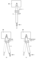
- FIG. 1 is a front view showing a machining center (machine tool equipped with an automatic tool changer) according to an embodiment of the present invention
- FIG. 1 is a side view showing a machining center (machine tool equipped with an automatic tool changer) according to an embodiment of the present invention
- Cross-sectional view showing the tool holder installed Block diagram showing the ATC runout detection system
- Cross-sectional view showing the tool holder being attached and detached
- High-frequency magnetic flux generated by an eddy current sensor visualized by computer simulation Graph showing distance vs. output voltage of an eddy current sensor Graph showing the results of analyzing the ratio of core length to coil length vs. sensitivity
- FIG. 1 shows a cross-sectional view of an eddy current sensor 1, where (a) is a conventional eddy current sensor 1, (b) is an example of the arrangement of a core 1-1, and (c) is an eddy current sensor 1 according to an embodiment of the present invention.
- the eddy current sensor 1 generates a high-frequency magnetic flux by passing a high-frequency current through the internal coil 1-2.
- the eddy current sensor 1 is installed so that its measurement end face 1-4 faces the outer peripheral surface of the flange portion 11B (see Figure 5) of the tool holder 11, which is the object to be measured.
- the spirally wound, disk-shaped coil 1-2 is held in shape by a plastic such as epoxy, and is then held in a bobbin 1-3, a cap-shaped cylindrical container made of resin.
- the bobbin 1-3 is housed in a cylindrical outer case 1-5.
- the outer diameter of the outer case 1-5 is ⁇ 5 mm
- the axial length is approximately 16 mm.
- the axial length, or coil length, of the coil 1-2 is approximately 2 mm.
- Figure 1(b) shows an example in which a core 1-1, a soft magnetic material made of ferrite or the like whose magnetic permeability does not decrease in the high frequency range, is placed on the measurement end face 1-4 side at the axial center of the coil 1-2 in the eddy current sensor 1.
- the axial length of the core 1-1 shown in Figure 1(b) is substantially equal to the axial length of the coil 1-2 which is the coil length. This increases the magnetic flux density penetrating the core 1-1 and improves the directivity, improving the sensitivity compared to the conventional eddy current sensor 1 in Figure 1(a).
- the core 1-1 is placed so as not to protrude from the end of the coil 1-2 on the measurement end face 1-4 side. In other words, the core 1-1 and the coil 1-2 are placed flat and without steps on the measurement end face 1-4 side (flush).
- FIG. 1(c) shows an eddy current sensor 1 according to one embodiment, in which core 1-1 extends backward, opposite measurement end face 1-4; in other words, the core length, which is the axial length of core 1-1, extends further away from measurement end face 1-4 than the coil length, which is the axial length of coil 1-2.
- the ratio of core length to coil length is approximately 1.50 (150%). This increases the magnetic flux density penetrating core 1-1 and improves directionality, resulting in improved sensitivity compared to the eddy current sensor 1 in FIG. 1(b).
- the distance between the eddy current sensor 1 and the object to be measured (metal), i.e., the distance d (see Figure 5) between the eddy current sensor 1 and the outer peripheral surface of the flange portion 11B of the tool holder 11, can be increased, so that it is possible to avoid collision between the eddy current sensor 1 and the tool holder 11 by increasing the distance d (see Figure 5).
- FIG. 1 is a front view of the machining center 20 according to an embodiment of the present invention
- Figure 3 is a side view.
- a workpiece 24 (which serves as the object to be machined during machining and the object to be measured during measurement) is placed on the top surface of a movable table 21 of a machining center 20 and fixed by a fixture 23.
- a spindle head 26 to which a mounting tool 25-1 is attached is disposed above the workpiece 24.
- the machining center 20 is a numerically controlled machine tool that performs various machining operations such as milling, drilling, boring, and tapping without changing the attachment of the workpiece 24.
- a large number of tools 25 are stored in the tool magazine 28. Then, machining is performed by automatically changing the tools 25 according to computer numerical control commands. Therefore, since machining is the main purpose, the environment in which the machining center 20 is installed contains fine particles such as oil mist and dust, and furthermore, there is dirt and cutting chips around the workpiece and spindle.
- the spindle head 26 is equipped with a mechanism for feeding the tool 25 vertically and a mechanism for rotating it in a horizontal plane, and the tool spindle 29 serves as the axis of rotation about which the attached tool 25-1 rotates.
- the tools 25 are individually attached to the tool holder 11 by the automatic tool changer (ATC device) 27, and the tool holder 11 is automatically attached to and detached from the spindle head 26.
- ATC device automatic tool changer
- the automatic tool changer (ATC device) 27 uses the arm 17 under the control of the control device 22 to take out the attached tool 25-1 from the tool magazine 28 that stores the tools 25 via the tool holder 11.
- the automatic tool changer (ATC device) 27 also has a mechanism for attaching and detaching the attached tool 25-1 to the spindle head 26 and storing it in the tool magazine 28.
- the series of controls related to the movement of the movable table 21 in the X-axis and Y-axis directions, the movement of the spindle head 26 in the Z-axis direction, the replacement control of the attached tool 25-1, machining such as cutting, and the measurement of the shape and machining error of the workpiece 24 are performed by the control device 22 by executing the machining and measurement programs stored therein.
- FIG. 4 is a cross-sectional view showing the attachment state of the tool holder, showing the state in which the tool holder 11 is attached to the spindle head 26.
- the tool holder 11 has a conical fitting portion 11A, and is attached by fitting the fitting portion 11A into a conical fitted portion 26A formed on the spindle head 26.
- the shaft rod 33 is pulled upward, which moves the ball holder 34 and balls 35.
- FIG. 5 is a block diagram showing the ATC runout detection system, showing the shape measuring unit 50 of the flange portion 11B of the tool holder 11 that holds the attached tool 25-1.
- the shape measuring unit 50 is a device that automatically detects the mounting state of the tool holder 11 mounted on the spindle head 26 in the ATC device, and is mainly composed of an eddy current sensor 1 and a data processing device 3.
- the eddy current sensor 1 is attached to the spindle head 26 via a bracket 10.
- the eddy current sensor 1 detects the distance d to the outer peripheral surface of the flange portion 11B of the tool holder 11 mounted on the spindle head 26 as a signal voltage.
- the shape of the tool holder 11 is standardized and uniform not only for the fitting portion 11A, but also for the outer peripheral shape of the flange portion 11B. Therefore, by measuring the outer peripheral shape of the flange portion 11B, the mounting state of the mounting tool 25-1 can be determined. The outer peripheral shape can be determined by rotating the tool holder 11 once and measuring the distance d.
- the data processing device 3 detects runout indicating the mounting state of the mounting tool 25-1 in the tool holder 11 based on the data measured by the eddy current sensor 1, and includes an A/D converter 4, a CPU 6, a memory 5, an input/output circuit 7, etc.
- the A/D converter 4 converts the signal voltage output from the eddy current sensor 1 into a digital signal and outputs it to the CPU 6.
- the data processing device 3 detects the runout indicating the mounting state of the mounting tool 25-1 attached to the spindle head 26 based on the data converted into a digital signal.
- the calculation process of the distance d by the CPU 6 is performed upon receiving a command to start measurement from the control device 22 via the input/output circuit 7.
- the data of the distance d output from the eddy current sensor 1 is then stored in the memory 5.
- Figure 6 is a cross-sectional view showing the attachment and detachment state of the tool holder 11, and shows the state when the tool holder 11 with the attached tool 25-1 is attached to and detached from the spindle head 26.
- the tool holder 11 does not wobble and is attached and detached from the spindle head 26 as shown by the arrow.
- Figure 6(b) if the tool holder 11 is attached and detached while tilting and wobbling, the flange portion 11B of the tool holder 11 and the eddy current sensor 1 collide.
- Figure 7 shows how high-frequency magnetic flux is generated by eddy current sensor 1.
- eddy current sensor 1 when high-frequency current is passed through coil 1-2, high-frequency magnetic flux is generated radially toward flange portion 11B, which is the target metal.
- the sensitivity of coil 1-2 can be increased and the distance d can be increased by increasing the diameter.
- the range of the high-frequency magnetic flux will be larger than the thickness H of the flange portion 11B to be measured, resulting in the influence of surrounding metal.
- the diameter of coil 1-2 is smaller than the thickness H of flange portion 11B. Note that while it is better for the diameter of core 1-1 to be larger, it should be determined in conjunction with the diameter of coil 1-2 and should be within the inner diameter of coil 1-2.
- Figure 8 is a diagram visualizing the high-frequency magnetic flux from an eddy current sensor 1 using a computer simulation;
- Figure 8(a) shows the magnetic flux distribution in Figure 1(a), i.e., when there is no core 1-1;
- Figure 8(b) shows the magnetic flux distribution in Figure 1(b), i.e., when there is a core 1-1 with a length substantially equal to the coil length;
- Figure 8(c) shows the magnetic flux distribution in Figure 1(c), when a high-frequency current is passed through an eddy current sensor 1 with a core 1-1 longer than the coil length.
- the high-frequency magnetic flux spreads radially from the tip of the coil 1-2 (measurement end surface 1-4), and the magnetic flux in the center facing the flange portion 11B is sparse and has a low magnetic flux density.
- the magnetic flux in the center is denser than in Figure 8(a) (the magnetic flux is concentrated and appears darker in the figure), and it can be seen that the magnetic flux density is higher.
- the sensitivity of the eddy current sensor 1 can be adjusted by changing the material of the core 1-1, and the detection distance of the eddy current sensor 1 can be controlled.
- the sensitivity adjustment is necessary so as not to exceed the allowable input voltage range of the data processing device 3 (see Figure 5).
- the sensitivity and detection distance can be adjusted appropriately according to the purpose without increasing the size of the eddy current sensor 1.
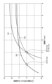
- Figure 9 is a graph showing distance d versus output voltage of eddy current sensor 1.
- the vertical axis shows the output voltage (V) of eddy current sensor 1
- the horizontal axis shows distance d from eddy current sensor 1 to the outer peripheral surface of flange portion 11B.
- Figure 9(a) shows the results of measurements using eddy current sensor 1 shown in Figure 1(a)
- Figure 9(b) shows the results of measurements using eddy current sensor 1 shown in Figure 1(b)
- Figure 9(c) shows the results of measurements using eddy current sensor 1 shown in Figure 1(c).
- the slope of each graph represents the sensitivity of eddy current sensor 1. In order to increase sensitivity, it is preferable to install eddy current sensor 1 at a point where the slope is large.
- Figure 9(a) shows an eddy current sensor 1 without a core 1-1.
- the sensitivity was 7 V/mm.
- Figure 9(b) shows an eddy current sensor 1 with the core 1-1 placed as in Figure 1(b).
- the eddy current sensor 1 was placed at point B so that the distance d was 2 mm, the sensitivity was 7 V/mm.
- the eddy current sensor 1 with the core 1-1 placed can increase the distance d without reducing sensitivity compared to when the core 1-1 is not placed.
- the core 1-1 is extended backward as in Figure 1(c), and when the eddy current sensor 1 is installed at point B so that the distance d is 2 mm, the sensitivity is 14 V/mm.
- the eddy current sensor 1 with the extended core 1-1 not only increases the distance d compared to when the core 1-1 is not present, but also improves the sensitivity. Therefore, the eddy current sensor 1 with the extended core 1-1 not only avoids collisions between the eddy current sensor 1 and the tool holder 11, but also increases the directivity and improves the sensitivity without increasing the diameter of the coil 1-2.
- Figure 10 is a graph showing the results of an analysis of sensitivity versus the ratio of core length to coil length.
- the horizontal axis shows the ratio of core length to coil length (core length/coil length, in %), and the vertical axis shows the sensitivity ratio, which is shown as a multiple based on the sensitivity of the conventional eddy current sensor 1.
- Figure 10 shows the results when the distance d is constant.
- the ratio of the core length, which is the axial length of core 1-1, to the coil length, which is the axial length of coil 1-2, (core length/coil length) should be 135 to 165% (1.35 to 1.65) (range M in the figure) to improve sensitivity at a position where distance d is doubled as shown in Figure 9, and more preferably 140 to 160% (1.40 to 1.60). Also, from the perspective of further improving sensitivity, it is preferable that the core length ratio (core length/coil length) be 170% (1.70) or less.
- Reference Signs List 1 Eddy current sensor 1-1: Core 1-2: Coil 1-3: Bobbin 1-4: Measurement end surface 1-5: Outer case 3: Data processing device 4: A/D converter 5: Memory 6: CPU 7... Input/Output circuit 10... Bracket 11... Tool holder 11A... Fitting portion 11B... Flange portion 17... Arm 20... Machining center 21... Movable table 22... Control device 23... Fixture 24... Workpiece 25... Tool 25-1... Tool to be mounted 26... Spindle head 26A... Fitted portion 28... Tool magazine 29... Tool spindle 33... Shaft rod 34... Ball holder 35... Ball 50... Shape measuring portion
Landscapes
- General Physics & Mathematics (AREA)
- Physics & Mathematics (AREA)
- Chemical & Material Sciences (AREA)
- Life Sciences & Earth Sciences (AREA)
- Biochemistry (AREA)
- Chemical Kinetics & Catalysis (AREA)
- Electrochemistry (AREA)
- Health & Medical Sciences (AREA)
- Engineering & Computer Science (AREA)
- Analytical Chemistry (AREA)
- Mechanical Engineering (AREA)
- General Health & Medical Sciences (AREA)
- Immunology (AREA)
- Pathology (AREA)
- Machine Tool Sensing Apparatuses (AREA)
- Measurement Of Length, Angles, Or The Like Using Electric Or Magnetic Means (AREA)
- Automatic Tool Replacement In Machine Tools (AREA)
- Gripping On Spindles (AREA)
Priority Applications (2)
| Application Number | Priority Date | Filing Date | Title |
|---|---|---|---|
| EP24778830.0A EP4663344A1 (en) | 2023-03-24 | 2024-02-19 | Machine tool with automatic tool changer, and eddy current sensor used for same |
| CN202480018302.3A CN120882526A (zh) | 2023-03-24 | 2024-02-19 | 带有自动工具更换装置的机床及其使用的涡电流传感器 |
Applications Claiming Priority (2)
| Application Number | Priority Date | Filing Date | Title |
|---|---|---|---|
| JP2023047701A JP2024136551A (ja) | 2023-03-24 | 2023-03-24 | 自動工具交換装置付き工作機械及びそれに用いられる渦電流センサ |
| JP2023-047701 | 2023-03-24 |
Publications (1)
| Publication Number | Publication Date |
|---|---|
| WO2024202685A1 true WO2024202685A1 (ja) | 2024-10-03 |
Family
ID=92904184
Family Applications (1)
| Application Number | Title | Priority Date | Filing Date |
|---|---|---|---|
| PCT/JP2024/005678 Ceased WO2024202685A1 (ja) | 2023-03-24 | 2024-02-19 | 自動工具交換装置付き工作機械及びそれに用いられる渦電流センサ |
Country Status (4)
| Country | Link |
|---|---|
| EP (1) | EP4663344A1 (https=) |
| JP (1) | JP2024136551A (https=) |
| CN (1) | CN120882526A (https=) |
| WO (1) | WO2024202685A1 (https=) |
Citations (7)
| Publication number | Priority date | Publication date | Assignee | Title |
|---|---|---|---|---|
| JPS516050A (ja) * | 1974-07-03 | 1976-01-19 | Hitachi Ltd | Hisetsushokushikisadogatakenshutsuki |
| JPS5560801A (en) * | 1978-10-31 | 1980-05-08 | Toshiba Corp | Displacement detector |
| JP2002200542A (ja) * | 2000-10-27 | 2002-07-16 | Tokyo Seimitsu Co Ltd | 工作機械 |
| JP2005140769A (ja) * | 2003-10-15 | 2005-06-02 | Sumitomo Chemical Co Ltd | 粉体定量排出器の異常検出方法 |
| JP2009014258A (ja) * | 2007-07-04 | 2009-01-22 | Sumitomo Chemical Co Ltd | 攪拌乾燥機の異常検出方法。 |
| JP2017067670A (ja) * | 2015-10-01 | 2017-04-06 | 株式会社エヌエステイー | 変位測定装置 |
| JP2018089738A (ja) | 2016-12-02 | 2018-06-14 | 株式会社東京精密 | 自動工具交換装置付き工作機械及び自動測定方法 |
-
2023
- 2023-03-24 JP JP2023047701A patent/JP2024136551A/ja active Pending
-
2024
- 2024-02-19 EP EP24778830.0A patent/EP4663344A1/en active Pending
- 2024-02-19 WO PCT/JP2024/005678 patent/WO2024202685A1/ja not_active Ceased
- 2024-02-19 CN CN202480018302.3A patent/CN120882526A/zh active Pending
Patent Citations (7)
| Publication number | Priority date | Publication date | Assignee | Title |
|---|---|---|---|---|
| JPS516050A (ja) * | 1974-07-03 | 1976-01-19 | Hitachi Ltd | Hisetsushokushikisadogatakenshutsuki |
| JPS5560801A (en) * | 1978-10-31 | 1980-05-08 | Toshiba Corp | Displacement detector |
| JP2002200542A (ja) * | 2000-10-27 | 2002-07-16 | Tokyo Seimitsu Co Ltd | 工作機械 |
| JP2005140769A (ja) * | 2003-10-15 | 2005-06-02 | Sumitomo Chemical Co Ltd | 粉体定量排出器の異常検出方法 |
| JP2009014258A (ja) * | 2007-07-04 | 2009-01-22 | Sumitomo Chemical Co Ltd | 攪拌乾燥機の異常検出方法。 |
| JP2017067670A (ja) * | 2015-10-01 | 2017-04-06 | 株式会社エヌエステイー | 変位測定装置 |
| JP2018089738A (ja) | 2016-12-02 | 2018-06-14 | 株式会社東京精密 | 自動工具交換装置付き工作機械及び自動測定方法 |
Non-Patent Citations (1)
| Title |
|---|
| See also references of EP4663344A1 |
Also Published As
| Publication number | Publication date |
|---|---|
| JP2024136551A (ja) | 2024-10-04 |
| CN120882526A (zh) | 2025-10-31 |
| EP4663344A1 (en) | 2025-12-17 |
Similar Documents
| Publication | Publication Date | Title |
|---|---|---|
| US11022530B2 (en) | System and method for determining structural characteristics of a machine tool | |
| JP6921511B2 (ja) | 自動工具交換装置付き工作機械及び自動測定方法 | |
| KR101990157B1 (ko) | 미세-방전 기반 계측 시스템 | |
| Liu | Repetitive measurement and compensation to improve workpiece machining accuracy | |
| WO2024202685A1 (ja) | 自動工具交換装置付き工作機械及びそれに用いられる渦電流センサ | |
| JPS62218052A (ja) | 工具の破損および摩耗を非接触監視する方法および装置 | |
| JP2001341052A (ja) | ワークの加工方法および工具の折損検出方法並びに加工装置 | |
| CN118549335B (zh) | 焊线质检装置、焊线质检系统及焊线质检方法 | |
| JP4658046B2 (ja) | 機械部品の位置を検査するための装置および方法 | |
| CN111141207B (zh) | 一种三维电涡流传感器测头 | |
| JP6719906B2 (ja) | 渦電流センサ及びそれを備えたツールホルダ装着状態検出装置 | |
| JP6807002B2 (ja) | 計測システム | |
| JP2016080507A (ja) | 工作機械における座標測定システム | |
| CN107088789A (zh) | 基于光纤激光测振仪的数控机床主轴轴心轨迹测量装置 | |
| EP4255669B1 (en) | System for checking the integrity of a tool | |
| KR100485569B1 (ko) | 엘씨 발진회로를 이용한 드로바유니트의 위치 감지기구 | |
| JP2004230506A (ja) | 放電細穴加工機における電極下ガイドの位置決め方法 | |
| JPH079306A (ja) | 被工作物の表面付近の凹凸を検出するための装置 | |
| GB2319615A (en) | Position measurement apparatus | |
| JP2025018916A (ja) | 非接触で破損監視および/または摩耗監視する装置並びに方法 | |
| JP7124242B1 (ja) | ツールホルダ装着状態検出方法及び装置、並びに工作機械 | |
| JPH04283051A (ja) | プリント基板加工機の工具振れ検出装置 | |
| CN107931635A (zh) | 一种用于检测双刀架车床的主轴尾顶同轴度的装置和方法 | |
| US11061381B1 (en) | Encoder based machining quality prognostics | |
| CN107984299A (zh) | 自适应的精密加工自动对刀系统及方法 |
Legal Events
| Date | Code | Title | Description |
|---|---|---|---|
| 121 | Ep: the epo has been informed by wipo that ep was designated in this application |
Ref document number: 24778830 Country of ref document: EP Kind code of ref document: A1 |
|
| WWE | Wipo information: entry into national phase |
Ref document number: 202480018302.3 Country of ref document: CN |
|
| NENP | Non-entry into the national phase |
Ref country code: DE |
|
| WWP | Wipo information: published in national office |
Ref document number: 202480018302.3 Country of ref document: CN |
|
| WWP | Wipo information: published in national office |
Ref document number: 2024778830 Country of ref document: EP |