WO2024202313A1 - 案内部材及び電池パック - Google Patents
案内部材及び電池パック Download PDFInfo
- Publication number
- WO2024202313A1 WO2024202313A1 PCT/JP2023/045291 JP2023045291W WO2024202313A1 WO 2024202313 A1 WO2024202313 A1 WO 2024202313A1 JP 2023045291 W JP2023045291 W JP 2023045291W WO 2024202313 A1 WO2024202313 A1 WO 2024202313A1
- Authority
- WO
- WIPO (PCT)
- Prior art keywords
- guide groove
- wiring member
- voltage wiring
- low
- locking
- Prior art date
- Legal status (The legal status is an assumption and is not a legal conclusion. Google has not performed a legal analysis and makes no representation as to the accuracy of the status listed.)
- Ceased
Links
Images


Classifications
-
- H—ELECTRICITY
- H01—ELECTRIC ELEMENTS
- H01M—PROCESSES OR MEANS, e.g. BATTERIES, FOR THE DIRECT CONVERSION OF CHEMICAL ENERGY INTO ELECTRICAL ENERGY
- H01M50/00—Constructional details or processes of manufacture of the non-active parts of electrochemical cells other than fuel cells, e.g. hybrid cells
- H01M50/20—Mountings; Secondary casings or frames; Racks, modules or packs; Suspension devices; Shock absorbers; Transport or carrying devices; Holders
- H01M50/298—Mountings; Secondary casings or frames; Racks, modules or packs; Suspension devices; Shock absorbers; Transport or carrying devices; Holders characterised by the wiring of battery packs
-
- H—ELECTRICITY
- H01—ELECTRIC ELEMENTS
- H01M—PROCESSES OR MEANS, e.g. BATTERIES, FOR THE DIRECT CONVERSION OF CHEMICAL ENERGY INTO ELECTRICAL ENERGY
- H01M50/00—Constructional details or processes of manufacture of the non-active parts of electrochemical cells other than fuel cells, e.g. hybrid cells
- H01M50/20—Mountings; Secondary casings or frames; Racks, modules or packs; Suspension devices; Shock absorbers; Transport or carrying devices; Holders
- H01M50/204—Racks, modules or packs for multiple batteries or multiple cells
-
- H—ELECTRICITY
- H02—GENERATION; CONVERSION OR DISTRIBUTION OF ELECTRIC POWER
- H02G—INSTALLATION OF ELECTRIC CABLES OR LINES, OR OF COMBINED OPTICAL AND ELECTRIC CABLES OR LINES
- H02G3/00—Installations of electric cables or lines or protective tubing therefor in or on buildings, equivalent structures or vehicles
- H02G3/30—Installations of cables or lines on walls, floors or ceilings
- H02G3/32—Installations of cables or lines on walls, floors or ceilings using mounting clamps
-
- Y—GENERAL TAGGING OF NEW TECHNOLOGICAL DEVELOPMENTS; GENERAL TAGGING OF CROSS-SECTIONAL TECHNOLOGIES SPANNING OVER SEVERAL SECTIONS OF THE IPC; TECHNICAL SUBJECTS COVERED BY FORMER USPC CROSS-REFERENCE ART COLLECTIONS [XRACs] AND DIGESTS
- Y02—TECHNOLOGIES OR APPLICATIONS FOR MITIGATION OR ADAPTATION AGAINST CLIMATE CHANGE
- Y02E—REDUCTION OF GREENHOUSE GAS [GHG] EMISSIONS, RELATED TO ENERGY GENERATION, TRANSMISSION OR DISTRIBUTION
- Y02E60/00—Enabling technologies; Technologies with a potential or indirect contribution to GHG emissions mitigation
- Y02E60/10—Energy storage using batteries
Definitions
- the present invention relates to a guide member and a battery pack.
- a battery pack includes multiple battery modules.
- a battery module includes multiple battery cells. The multiple battery cells are electrically connected to each other in a series and parallel combination. Wiring members such as harnesses are electrically connected to the battery modules.
- Patent Document 1 describes a holder that detachably holds wire.
- the holder has a first storage section and a second storage section that can store the wire.
- a wall piece is provided between the first storage section and the second storage section to separate the first storage section and the second storage section from each other.
- Patent document 2 describes a clamping device for attaching a tube to a mounting surface.
- the clamping device has a pair of clamping grooves separated from each other by a boss portion, and a tube is inserted into each of the pair of clamping grooves.
- JP 2019-113160 A Japanese Utility Model Application Publication No. 3-059578
- a guide member that defines a number of guide grooves extending in a specific direction may be used.
- the guide member includes a partition wall that separates adjacent guide grooves from each other, and a locking structure that locks the wiring members inserted into each guide groove.
- the width of the partition wall needs to be widened in order to maintain the strength of the partition wall around the locking structure.
- widening the width of the partition wall may result in an increase in the size of the guide member.
- simply narrowing the width of the partition wall may result in a decrease in the strength of the guide member around the locking structure.
- One object of the present invention is to achieve both miniaturization and high strength of the guide member. Other objects of the present invention will become apparent from the description of this specification.
- a partition wall separating a plurality of guide grooves extending in a predetermined direction from each other; a locking structure that locks a wiring member inserted into each guide groove and has at least a portion provided on the partition wall; Equipped with A guide member, in which the locking structures of each guide groove are positioned offset from each other in the predetermined direction.
- the above aspect of the present invention makes it possible to achieve both miniaturization and high strength of the guide member.
- FIG. 1 is a schematic perspective view of a battery pack according to an embodiment
- 2 is a schematic top view of the battery pack according to the embodiment with the upper case removed.
- FIG. 3 is a detailed top view of an area ⁇ surrounded by a dashed line drawn around the periphery between two battery modules located at the front of the lower case in FIG. 2.
- FIG. 3 is a detailed top view of an area ⁇ surrounded by a dashed line drawn around the periphery between the rear portions of two battery modules located in the center of the lower case in FIG. 2.
- FIG. FIG. 4 is a left side view of a first guide member and a second guide member according to the embodiment. This is a cross-sectional view taken along line AA in FIG.
- FIG. 8 is a diagram showing a modification of FIG. 7 .
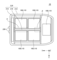
- FIG. 1 is a schematic perspective view of a battery pack 10 according to an embodiment.
- FIG. 2 is a schematic top view of a battery pack 10 according to an embodiment with the upper case 220 removed.
- the battery pack 10 is mounted on an automobile. Specifically, the battery pack 10 is mounted between the front and rear wheels of the automobile. In the following, unless otherwise specified, the battery pack 10 will be described as being mounted on an automobile. However, the battery pack 10 can also be used for purposes other than automobiles.
- the X direction indicates the front-rear direction of the battery pack 10.
- the Y direction is perpendicular to the X direction.
- the Y direction indicates the left-right direction of the battery pack 10.
- the Z direction is perpendicular to both the X and Y directions.
- the Z direction indicates the up-down direction of the battery pack 10.
- the arrows pointing to the X direction, the Y direction, and the Z direction indicate the front, left, and up directions of the battery pack 10, respectively.
- the white circle with a black dot indicating the Z direction indicates that the arrow pointing to the Z direction extends from the back of the page to the front.
- the relationship between the X, Y, and Z directions and the front-rear, left-right, and up-down directions of the battery pack 10 is not limited to this example.
- the front-rear, left-right and up-down directions of the battery pack 10 are determined by the vehicle in which the battery pack 10 is mounted.
- the X, Y and Z directions indicate the front-rear, left-right and up-down directions of the vehicle, respectively.
- the arrow pointing to the X direction, the arrow pointing to the Y direction and the arrow pointing to the Z direction indicate the front, left and up directions of the vehicle, respectively.
- the relationship between the front-rear, left-right and up-down directions of the battery pack 10 and the front-rear, left-right and up-down directions of the vehicle is not limited to this example.
- the direction perpendicular to the Z direction will be referred to as the horizontal direction.
- the battery pack 10 includes a plurality of battery modules 100 and a housing 200.
- the battery pack 10 when viewed from the Z direction, the battery pack 10 includes four battery modules 100 arranged around the approximate center of the housing 200 and one battery module 100 arranged at the rear of the housing 200.
- the number and arrangement of the battery modules 100 included in the battery pack 10 are not limited to this example. For example, it is sufficient that there are multiple battery modules 100 arranged around the approximate center of the housing 200, and the battery module 100 arranged at the rear of the housing 200 may be omitted depending on the capacity required for the battery pack 10.
- the housing 200 has a lower case 210, an upper case 220, and a pair of terminals 230.
- the lower case 210 may generally be referred to as, for example, a tray or a main body.
- the lower case 210 includes a lower plate 212, an outer frame 214, and an inner frame 216.
- the upper case 220 may generally be referred to as, for example, a cover or lid.
- the multiple battery modules 100 are mounted on the upper surface side of the lower plate 212.
- Each battery module 100 has multiple battery cells (not shown) stacked horizontally, and a housing case 110 that houses the multiple battery cells.
- a housing case 110 that houses the multiple battery cells.
- multiple battery cell groups each including multiple battery cells connected in parallel, are connected in series.
- multiple single battery cells may be connected in series.
- the outer frame 214 When viewed from the Z direction, the outer frame 214 surrounds the multiple battery modules 100.
- a sealant (not shown) is disposed on the upper surface of the outer frame 214. Therefore, the lower case 210 and the upper case 220 can be attached to each other with the sealant disposed between the upper surface of the outer frame 214 and the lower surface of the portion of the upper case 220 that overlaps with the outer frame 214 in the Z direction. Therefore, the lower case 210 and the upper case 220 can form a storage space in which the multiple battery modules 100 are housed.
- the inner frame 216 When viewed from the Z direction, the inner frame 216 is located in an area surrounded by the outer frame 214. When viewed from the Z direction, the inner frame 216 at least partially surrounds the four battery modules 100. As mentioned above, the number and arrangement of the battery modules 100 included in the battery pack 10 are not limited to this example, and the number of battery modules 100 surrounded by the inner frame 216 is not limited to four, but may be, for example, two or more than four.
- the pair of terminals 230 are provided in front of the outer frame 214.
- the pair of terminals 230 are arranged approximately parallel to each other in the Y direction.
- the front end of each terminal 230 protrudes forward from the front surface of the outer frame 214.
- the multiple battery modules 100 are connected in series between the pair of terminals 230.
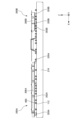
- FIG. 3 is a detailed top view of the area ⁇ surrounded by a dashed line drawn around the periphery between the two battery modules 100 located at the front of the lower case 210 in FIG. 2.
- FIG. 4 is a detailed top view of the area ⁇ surrounded by a dashed line drawn around the periphery between the rear of the two battery modules 100 located at the center of the lower case 210 in FIG. 2.
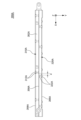
- FIG. 5 is a left side view of the first guide member 300A and the second guide member 300B according to the embodiment.
- FIG. 6 is a cross-sectional view taken along line A-A in FIG. 3.
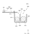
- FIG. 7 is a cross-sectional view taken along line B-B in FIG. 3.
- FIG. 8 is a top view of the first guide member 300A with the first low-voltage wiring member 510A and the first lower high-voltage wiring member 520A removed.
- FIG. 9 is a cross-sectional view taken along line C-C in FIG. 3.
- the battery pack 10 includes a first guide member 300A, a second guide member 300B, a first support 400A, a second support 400B, a first low voltage wiring member 510A, a second low voltage wiring member 510B, a first lower high voltage wiring member 520A, a second lower high voltage wiring member 520B, and an upper high voltage wiring member 530.
- the first guide member 300A includes a first bottom 302A, a first right wall 304A, a first left wall 306A, a first partition 308A, and a plurality of first support legs 350A.
- the second guide member 300B includes a second bottom 302B, a second right wall 304B, a second left wall 306B, a second partition 308B, and a plurality of second support legs 350B.
- the first support 400A has a first extension 410A and a plurality of first mounting protrusions 420A.
- the second support 400B has a second extension 410B and a plurality of second mounting protrusions 420B.
- first guide member 300A, the second guide member 300B, the first support 400A, the second support 400B, the first low voltage wiring member 510A, the first lower high voltage wiring member 520A, and the upper high voltage wiring member 530 will be described.
- the first guide member 300A when viewed from the Z direction, is located between two battery modules 100 lined up in the Y direction at the front of the lower case 210 in the X direction.
- the first guide member 300A defines a first right guide groove 310A and a first left guide groove 320A.
- the first right guide groove 310A and the first left guide groove 320A extend approximately parallel to the Y direction.
- the second guide member 300B when viewed from the Z direction, is located between the rear parts of the two battery modules 100 aligned in the Y direction at approximately the center of the lower case 210 in the X direction.
- the second guide member 300B defines a second right guide groove 310B and a second left guide groove 320B.
- the second right guide groove 310B and the second left guide groove 320B extend approximately parallel to the Y direction.
- the first support 400A when viewed from the Z direction, is located to the left of the first guide member 300A.
- the first extension portion 410A extends approximately parallel to the Y direction.
- the multiple first mounting protrusions 420A protrude rightward from the right side of the first extension portion 410A.
- the second support 400B when viewed from the Z direction, is located to the left of the second guide member 300B.
- the second extension portion 410B extends approximately parallel to the Y direction.
- the multiple second mounting protrusions 420B protrude rightward from the right side of the second extension portion 410B.
- the first low-voltage wiring member 510A is inserted into the first right guide groove 310A. Therefore, the first low-voltage wiring member 510A extends along the first right guide groove 310A approximately parallel to the X direction.
- the first low-voltage wiring member 510A is a harness.
- the first low-voltage wiring member 510A includes a plurality of first low-voltage wirings 512A. In the first right guide groove 310A, the plurality of first low-voltage wirings 512A are bound together by a bundling member such as a tape or a tube.
- the plurality of first low-voltage wirings 512A include low-voltage wiring such as wiring that operates as a signal line or wiring that constitutes a circuit made of a 12V power supply for a vehicle.
- the first low-voltage wiring member 510A may be composed of a single low-voltage wiring.
- the second low-voltage wiring member 510B is inserted into the second right guide groove 310B. Therefore, the second low-voltage wiring member 510B extends approximately parallel to the X direction along the second right guide groove 310B.
- the second low-voltage wiring member 510B is a harness. Similar to the first low-voltage wiring member 510A, the second low-voltage wiring member 510B includes multiple low-voltage wirings bundled together in the second right guide groove 310B. However, the second low-voltage wiring member 510B may be composed of a single low-voltage wiring.
- the first lower high-voltage wiring member 520A is inserted into the first left guide groove 320A. Therefore, the first lower high-voltage wiring member 520A extends approximately parallel to the Y direction along the first left guide groove 320A.
- the first lower high-voltage wiring member 520A is a harness.
- the first lower high-voltage wiring member 520A includes a plurality of first lower high-voltage wirings 522A. In the first left guide groove 320A, the plurality of first lower high-voltage wirings 522A are bundled together by a bundling member such as a tape or a tube.
- the plurality of first lower high-voltage wirings 522A include high-voltage wiring such as a voltage detection line that detects the voltage of each battery cell included in the battery module 100 and a thermistor signal line that detects the temperature of each battery cell included in the battery module 100.
- the first lower high-voltage wiring member 520A may be composed of a single wiring.
- the second lower high voltage wiring member 520B is inserted into the second left guide groove 320B. Therefore, the second lower high voltage wiring member 520B extends approximately parallel to the Y direction along the second left guide groove 320B.
- the second lower high voltage wiring member 520B is a harness. Similar to the first lower high voltage wiring member 520A, the second lower high voltage wiring member 520B includes multiple high voltage wirings bundled together in the second left guide groove 320B. However, the second lower high voltage wiring member 520B may be composed of a single high voltage wiring.
- the upper high-voltage wiring member 530 is mounted on the upper surfaces of both the first extension portion 410A and the second extension portion 410B.
- the upper high-voltage wiring member 530 extends approximately parallel to the Y direction along the first extension portion 410A and the second extension portion 410B.
- the upper high-voltage wiring member 530 is a harness.
- the upper high-voltage wiring member 530 includes a plurality of upper high-voltage wirings 532.
- the plurality of upper high-voltage wirings 532 are bundled together by a bundling member such as a tape or a tube.
- the plurality of upper high-voltage wiring members 530 include high-voltage wiring such as wiring for supplying power to a heater that heats each battery cell included in the battery module 100.
- the upper high-voltage wiring member 530 may be composed of a single high-voltage wiring.
- the first low-voltage wiring member 510A and the first lower high-voltage wiring member 520A are arranged approximately parallel to the X direction between two battery modules 100 arranged in the Y direction at the front of the lower case 210 using the first guide member 300A. Therefore, the first low-voltage wiring member 510A and the first lower high-voltage wiring member 520A can be protected from surrounding members by the first guide member 300A. In addition, even if the gap between two battery modules 100 arranged in the Y direction is relatively narrow, the workability of arranging the first low-voltage wiring member 510A and the first lower high-voltage wiring member 520A can be improved compared to when the first guide member 300A is not used.
- the first low-voltage wiring member 510A or the first lower high-voltage wiring member 520A is fixed to the battery module 100 by a clip without using the first guide member 300A, a relatively large space is required.
- the first low voltage wiring member 510A and the first lower high voltage wiring member 520A can be routed in a narrower space than when clips are used. The same is true for the second guide member 300B, the second low voltage wiring member 510B, and the second lower high voltage wiring member 520B.
- the first low-voltage wiring member 510A is arranged along the first right guide groove 310A with the multiple first low-voltage wirings 512A bundled together. Therefore, compared to when the multiple first low-voltage wirings 512A are not bundled together, it is easier to arrange the multiple first low-voltage wirings 512A along the first right guide groove 310A.
- the first lower high-voltage wiring member 520A is arranged along the first left guide groove 320A with the multiple first lower high-voltage wirings 522A bundled together. Therefore, compared to when the multiple first lower high-voltage wirings 522A are not bundled together, it is easier to arrange the multiple first lower high-voltage wirings 522A along the first left guide groove 320A.
- the first guide member 300A and the second guide member 300B will be described with reference to FIG. 5, and if necessary, with reference to FIG. 3 and FIG. 4.
- a plurality of support protrusions 112 protrude to the left from the left side surface of the storage case 110 of the battery module 100 located on the right front side of the center of the lower case 210 when viewed from the Z direction.
- each support protrusion 112 and the upper surface of the inner frame 216 are fastened to each other by a fastener 600. Therefore, the battery module 100 located on the right front side of the center of the lower case 210 when viewed from the Z direction is fixed to the lower case 210 via the fastener 600.
- the fastener 600 is a bolt.
- Each support protrusion 112 serves as a support part for fixing the storage case 110 and the lower case 210 to each other.
- a plurality of support protrusions 112 protrude to the right from the right side surface of the storage case 110 of the battery module 100 located on the left front side of the center of the lower case 210 when viewed from the Z direction. Therefore, the battery module 100 located on the left front side of the center of the lower case 210 can also be fixed to the lower case 210 via the fastener 600. The same applies to the battery modules 100 located on the right rear side and left rear side of the center of the lower case 210 when viewed from the Z direction.
- the first support legs 350A support the first bottom 302A of the first guide member 300A with the upper surface of the inner frame 216 of the lower case 210 and the lower surface of the first bottom 302A of the first guide member 300A spaced apart from each other via a gap.
- At least a portion of each of the support protrusions 112 and at least a portion of each of the fasteners 600 are located in the gap between the upper surface of the inner frame 216 and the lower surface of the first bottom 302A.
- the support protrusions 112 and the heads of the bolts of the fasteners 600 overlap each other in the Z direction.
- the support protrusions 112 are located between the upper surface of the inner frame 216 and the heads of the fasteners 600, and the support protrusions 112 and the heads of the fasteners 600 are located in the gap between the lower surface of the first bottom 302A and the upper surface of the inner frame 216. Therefore, in the example shown in FIG. 5, the first guide member 300A, the support protrusion 112, and the multiple fasteners 600 can be stacked on top of each other in the Z direction. In other words, it is not necessary to arrange the first guide member 300A, the support protrusion 112, and the heads of the fasteners 600 horizontally offset from each other.
- the first guide member 300A, the support protrusion 112, and the heads of the fasteners 600 can be arranged spatially more efficiently in the horizontal direction.
- multiple first support legs 350A are provided at two locations, the front and rear of the first bottom 302A.
- the position where the first support legs 350A are provided is not limited to this example.
- the second support legs 350B support the second bottom 302B of the second guide member 300B with the upper surface of the inner frame 216 of the lower case 210 and the lower surface of the second bottom 302B of the second guide member 300B spaced apart from each other via a gap. At least a portion of each of the support protrusions 112 and at least a portion of each of the fasteners 600 are located in the gap between the upper surface of the inner frame 216 and the lower surface of the second bottom 302B.
- the second guide member 300B, the support protrusions 112, and the heads of the fasteners 600 can be arranged spatially more efficiently in the horizontal direction compared to when the second guide member 300B, the support protrusions 112, and the heads of the fasteners 600 are arranged offset from each other in the horizontal direction.
- the first guide member 300A and the second guide member 300B are attached to the inner frame 216. Therefore, the load on the lower plate 212 can be reduced compared to when the first guide member 300A and the second guide member 300B are attached to the lower plate 212. Therefore, the lower plate 212 does not need to have high rigidity, and the structure is particularly suitable when the lower plate 212 is used as a cooling plate through which water-cooling piping or the like passes.
- the first guide member 300A and the second guide member 300B may be attached to the inner frame 216.
- the first guide member 300A and the second guide member 300B may be attached to the lower plate 212.
- the first guide member 300A will be described with reference to Figures 6 to 8.
- the first right wall 304A protrudes upward from the upper surface of the right end portion of the first bottom 302A.
- the first left wall 306A protrudes upward from the upper surface of the left end portion of the first bottom 302A.
- the first partition 308A protrudes upward from the upper surface of the portion between the lower end portion of the first right wall 304A and the lower end portion of the first left wall 306A of the first bottom 302A.
- the portion between the lower end portion of the first right wall 304A and the lower end portion of the first partition 308A of the first bottom 302A will be simply referred to as the right portion of the first bottom 302A
- the portion between the lower end portion of the first left wall 306A and the lower end portion of the first partition 308A of the first bottom 302A will be simply referred to as the left portion of the first bottom 302A.
- the bottom surface, right inner side surface, and left inner side surface of the first right guide groove 310A are defined by the upper surface of the right portion of the first bottom portion 302A, the left outer side surface of the first right wall 304A, and the right outer side surface of the first partition wall 308A, respectively.
- the first right guide groove 310A opens upward. Therefore, the first low-voltage wiring member 510A can be inserted into the first right guide groove 310A from above.
- the bottom surface, left inner side surface, and right inner side surface of the first left guide groove 320A are defined by the upper surface of the left portion of the first bottom portion 302A, the right outer side surface of the first left wall 306A, and the left outer side surface of the first partition wall 308A, respectively.
- the first left guide groove 320A opens upward. Therefore, the first lower high-voltage wiring member 520A can be inserted into the first left guide groove 320A from above.
- the first partition 308A is located between the first right guide groove 310A and the first left guide groove 320A in the Y direction. Specifically, the right outer side and the left outer side of the first partition 308A define the left inner side of the first right guide groove 310A and the right inner side of the first left guide groove 320A, respectively. Thus, the first partition 308A separates the first right guide groove 310A and the first left guide groove 320A from each other in the Y direction.
- the first guide member 300A has a pair of first locking portions 312A.
- the pair of first locking portions 312A are located on both sides of the first right guide groove 310A in the Y direction.
- the right first locking portion 312A is provided on the first right wall 304A.
- the left first locking portion 312A is provided on the first partition wall 308A.
- Each first locking portion 312A has a cantilever structure. Therefore, when viewed from the X direction, the pair of first locking portions 312A can bend toward the outside of the first right guide groove 310A in the Y direction. That is, when viewed from the X direction, the right first locking portion 312A can bend toward the right, and the left first locking portion 312A can bend toward the left.
- a first locking protrusion 312aA is provided at the upper end of each first locking portion 312A.
- each first locking protrusion 312aA protrudes toward the inside of the first right guide groove 310A in the Y direction. That is, when viewed from the X direction, the right first locking protrusion 312aA protrudes toward the left, and the left first locking protrusion 312aA protrudes toward the right.
- the upper surface of each first locking protrusion 312aA is inclined downward as it approaches the inside of the first right guide groove 310A in the Y direction.
- the lower surface of each first locking protrusion 312aA is inclined upward as it approaches the inside of the first right guide groove 310A in the Y direction.
- the first guide member 300A has a pair of second locking portions 322A.
- the pair of second locking portions 322A are located on both sides of the first left guide groove 320A in the Y direction.
- the left second locking portion 322A is provided on the first left wall 306A.
- the right second locking portion 322A is provided on the first partition wall 308A.
- Each second locking portion 322A has a cantilever structure. Therefore, when viewed from the X direction, the pair of second locking portions 322A can bend toward the outside of the first left guide groove 320A in the Y direction. That is, when viewed from the X direction, the left second locking portion 322A can bend toward the left, and the right second locking portion 322A can bend toward the right.
- a second locking protrusion 322aA is provided at the upper end of each second locking portion 322A.
- each second locking protrusion 322aA protrudes toward the inside of the first left guide groove 320A in the Y direction. That is, when viewed from the X direction, the left second locking protrusion 322aA protrudes toward the right, and the right second locking protrusion 322aA protrudes toward the left.
- the upper surface of each second locking protrusion 322aA is inclined downward as it approaches the inside of the first left guide groove 320A in the Y direction.
- the lower surface of each second locking protrusion 322aA is inclined upward as it approaches the inside of the first left guide groove 320A in the Y direction.
- the pair of first locking portions 312A form a locking structure that locks the first low-voltage wiring member 510A inserted into the first right guide groove 310A. Specifically, the pair of first locking portions 312A detachably lock the first low-voltage wiring member 510A into the first right guide groove 310A.
- the first low-voltage wiring member 510A is placed above the pair of first locking portions 312A.
- the minimum value of the width in the Y direction of the gap between the pair of first locking protrusions 312aA is less than the diameter of the first low-voltage wiring member 510A in a direction perpendicular to the X direction.
- the first low-voltage wiring member 510A is moved toward the first right guide groove 310A so that the lower surface of the first low-voltage wiring member 510A and the upper surfaces of each first locking protrusion 312aA come into contact with each other.
- the first low-voltage wiring member 510A is then pushed toward the first right guide groove 310A.
- the lower surface of the first low-voltage wiring member 510A slides against the upper surfaces of the pair of first locking protrusions 312aA and the pair of first locking portions 312A bend outward in the Y direction of the first right guide groove 310A.
- the first low-voltage wiring member 510A passes through the gap between the pair of first locking protrusions 312aA and enters the first right guide groove 310A.
- the pair of first locking portions 312A no longer receive external force from the first low-voltage wiring member 510A, and the Y-direction deflection of the pair of first locking portions 312A is released. Therefore, the minimum value of the Y-direction width of the gap between the pair of first locking protrusions 312aA becomes less than the diameter of the first low-voltage wiring member 510A in a direction perpendicular to the X-direction. Therefore, it is possible to prevent the first low-voltage wiring member 510A from detaching from the first right guide groove 310A through the gap between the pair of first locking protrusions 312aA. Therefore, the first low-voltage wiring member 510A is locked in the first right guide groove 310A.
- the following describes how to remove the first low-voltage wiring member 510A from the first right guide groove 310A.
- the first low-voltage wiring member 510A is moved upward so that the upper surface of the first low-voltage wiring member 510A and the lower surfaces of each of the first locking projections 312aA come into contact with each other.
- the first low-voltage wiring member 510A is pushed upward into the first right guide groove 310A.
- the upper surface of the first low-voltage wiring member 510A slides against the lower surfaces of the pair of first locking projections 312aA and the pair of first locking portions 312A bend outward in the Y direction of the first right guide groove 310A.
- the first low-voltage wiring member 510A passes through the gap between the pair of first locking protrusions 312aA and comes out of the first right guide groove 310A.
- the pair of first locking portions 312A no longer receive external force from the first low-voltage wiring member 510A, and the bending of the pair of first locking portions 312A in the Y direction is released.
- each first locking projection 312aA when viewed from the X direction, the upper surface of each first locking projection 312aA is inclined downward as it approaches the inside of the first right guide groove 310A in the Y direction. Therefore, compared to when the upper surface of each first locking projection 312aA is approximately parallel to the Y direction, when the first low-voltage wiring member 510A is pushed toward the first right guide groove 310A with the lower surface of the first low-voltage wiring member 510A and the upper surfaces of each first locking projection 312aA in contact with each other, the pair of first locking portions 312A can be easily deflected toward the outside of the first right guide groove 310A in the Y direction.
- each first locking projection 312aA when viewed from the X direction, the lower surface of each first locking projection 312aA is inclined upward as it approaches the inside of the first right guide groove 310A in the Y direction. Therefore, compared to a case in which the upper surface of each first locking projection 312aA is approximately parallel to the Y direction, when the first low-voltage wiring member 510A is pushed upward into the first right guide groove 310A with the upper surface of the first low-voltage wiring member 510A and the lower surfaces of each first locking projection 312aA in contact with each other, the pair of first locking portions 312A can be easily deflected toward the outside of the first right guide groove 310A in the Y direction.
- each first locking protrusion 312aA when viewed from the X direction, is curved along the outer surface of the first low-voltage wiring member 510A inserted into the first right guide groove 310A. Therefore, when viewed from the X direction, the gap between the lower surface of each first locking protrusion 312aA and the outer surface of the first low-voltage wiring member 510A can be reduced. Therefore, rattling of the first low-voltage wiring member 510A within the first right guide groove 310A can be suppressed.
- the pair of second locking portions 322A form a locking structure that locks the first lower high-voltage wiring member 520A inserted into the first left guide groove 320A.
- the pair of second locking portions 322A detachably lock the first lower high-voltage wiring member 520A to the first left guide groove 320A.
- the diameter of the first lower high-voltage wiring member 520A in a direction perpendicular to the X direction is less than the diameter of the first low-voltage wiring member 510A in a direction perpendicular to the X direction.
- the relationship between the diameter of the first low-voltage wiring member 510A and the diameter of the first lower high-voltage wiring member 520A is not limited to this example.
- the first guide member 300A will be described with reference to Figures 3 and 8, and, if necessary, Figures 6 and 7.
- the first right guide groove 310A has multiple pairs of first locking portions 312A arranged at non-equidistant intervals and substantially parallel to the X direction. However, the multiple pairs of first locking portions 312A may also be arranged at equal intervals and substantially parallel to the X direction.
- the first left guide groove 320A has multiple pairs of second locking portions 322A arranged at non-equidistant intervals and substantially parallel to the X direction. However, the multiple pairs of second locking portions 322A may also be arranged at equal intervals and substantially parallel to the X direction.
- the X-direction positions of the first locking portions 312A and the X-direction positions of the second locking portions 322A are offset from each other and are substantially parallel to the X-direction. Specifically, none of the first locking portions 312A provided on the first partition 308A and none of the second locking portions 322A provided on the first partition 308A are aligned in the X-direction.
- the strength of the first partition 308A around each of the first locking portions 312A and each of the second locking portions 322A can be improved with the width of the first partition 308A in the Y-direction narrowed. Therefore, in this embodiment, it is possible to achieve both a smaller size and higher strength for the first guide member 300A compared to the above-mentioned case.
- the X-direction spacing between each first locking portion 312A provided on first partition 308A and each second locking portion 322A provided on first partition 308A can be, for example, 50% or more of the Y-direction width of first partition 308A.
- the durability of first partition 308A around first locking portion 312A and second locking portion 322A can be improved compared to when the spacing is less than this numerical value.
- the distance in the X direction between each of the first locking portions 312A provided on the first partition 308A and each of the second locking portions 322A provided on the first partition 308A is the distance in the X direction between the portion of each of the first locking portions 312A closest to each of the second locking portions 322A and the portion of each of the second locking portions 322A closest to each of the first locking portions 312A, as illustrated by the letter "d" in FIG. 8.
- the first locking portion 312A is provided on both the first right wall 304A and the first partition 308A.
- the first locking portion 312A may not be provided on the first right wall 304A, and the first locking portion 312A may be provided on the first partition 308A.
- the second locking portion 322A is provided on both the first left wall 306A and the first partition 308A.
- the second locking portion 322A may not be provided on the first left wall 306A, and the second locking portion 322A may be provided on the first partition 308A.
- the letters "LV” are marked in three places on the top surface of the first bottom 302A in the first right guide groove 310A.
- "LV" means, for example, low pressure. Therefore, by marking with letters, numbers, figures, symbols, etc. on at least one of the top surface of the first bottom 302A in the first right guide groove 310A and the top surface of the first bottom 302A in the first left guide groove 320A, it is possible to indicate the wiring member to be inserted into each groove. Therefore, compared to a case where the mark is not marked, it is possible to prevent the wiring member from being erroneously inserted into each groove.
- the method of forming the mark is not particularly limited.
- the mark may be formed, for example, by embossing or by a laser marker.
- the engagement of the first low voltage wiring member 510A in the first right guide groove 310A and the engagement of the first lower high voltage wiring member 520A in the first left guide groove 320A described with reference to FIG. 3 and FIG. 6 to FIG. 8 can be similarly applied to the engagement of the second lower high voltage wiring member 520B in the second right guide groove 310B and the engagement of the second lower high voltage wiring member 520B in the second left guide groove 320B.
- the second guide member 300B has a pair of third engagement portions 312B and a pair of fourth engagement portions 322B.
- the pair of third engagement portions 312B are provided in the second right guide groove 310B.
- the pair of fourth engagement portions 322B are provided in the second left guide groove 320B.
- the first guide member 300A will be described with reference to Figure 9, and if necessary, with reference to Figure 3.
- a retaining protrusion 307A protrudes upward from the upper end of the first left wall 306A.
- the retaining protrusion 307A retains the right end of the first mounting protrusion 420A. Therefore, the Z-direction position of the first support 400A is higher than the Z-direction position of the first low voltage wiring member 510A and the Z-direction position of the first lower high voltage wiring member 520A. Therefore, the upper high voltage wiring member 530 can be supported at a higher position in the Z direction than the first right guide groove 310A and the first left guide groove 320A.
- noise interference between the upper high voltage wiring member 530 and the first low voltage wiring member 510A can be suppressed compared to the case where the Z-direction position of the upper high voltage wiring member 530 and the Z-direction position of the first low voltage wiring member 510A are aligned in the Z direction.
- noise interference between the first lower high-voltage wiring member 520A and the upper high-voltage wiring member 530 can be suppressed compared to when the Z-direction position of the upper high-voltage wiring member 530 and the Z-direction position of the first lower high-voltage wiring member 520A are aligned in the Z direction.
- the diameter of the upper high-voltage wiring member 530 in a direction perpendicular to the X direction is smaller than both the diameter of the first low-voltage wiring member 510A in a direction perpendicular to the X direction and the diameter of the first lower high-voltage wiring member 520A in a direction perpendicular to the X direction.
- the relationship between the diameter of the first low-voltage wiring member 510A, the diameter of the first lower high-voltage wiring member 520A, and the diameter of the upper high-voltage wiring member 530 is not limited to this example.
- the positional relationship between the first low voltage wiring member 510A, the first lower high voltage wiring member 520A, and the upper high voltage wiring member 530 described with reference to Figures 9 and 3 can also be applied to the positional relationship between the second low voltage wiring member 510B, the second lower high voltage wiring member 520B, and the upper high voltage wiring member 530.
- FIG. 10 shows a modified example of FIG. 7.
- a convex portion 321A is provided on the upper surface of the first bottom portion 302A in the first left guide groove 320A.
- the convex portion 321A is formed, for example, by a mark such as "LV" shown in FIG. 8.
- the Z-direction height of the convex portion 321A is adjusted to an appropriate height, even if a wiring member having a diameter larger than the diameter of the wiring member to be inserted into the first left guide groove 320A is inserted into the first left guide groove 320A, the pair of second locking protrusions 322aA contact the wiring member, and the Y-direction deflection of the pair of second locking portions 322A is not released. Therefore, compared to when the protrusion 321A does not exist, it is possible to prevent the wiring member from being erroneously inserted into the first left guide groove 320A. Also, the markings such as "LV" can be visually recognized as grooves through which wiring for the Lower Voltage side should be passed.
- each guide member defines two guide grooves extending in a given direction.
- a guide member may define three or more guide grooves extending in a given direction.
- 10 battery pack 100 battery module, 110 storage case, 112 support protrusion, 200 storage body, 210 lower case, 212 lower plate, 214 outer frame, 216 inner frame, 220 upper case, 230 terminal, 300A first guide member, 300B second guide member, 302A first bottom, 302B second bottom, 304A first right wall, 304B second right wall, 306A first left wall, 306B second left wall, 307A retaining protrusion, 308A first partition, 308B second partition, 310A first right guide groove, 310B second right guide groove, 312A first locking portion, 312B third locking portion, 312aA second 1 locking protrusion, 320A first left guide groove, 320B second left guide groove, 321A convex part, 322A second locking part, 322B fourth locking part, 322aA second locking protrusion, 350A first support leg, 350B second support leg, 400A first support body, 40 0B second support body, 410A first extension part, 410B second extension part,
Landscapes
- Chemical & Material Sciences (AREA)
- Chemical Kinetics & Catalysis (AREA)
- Electrochemistry (AREA)
- General Chemical & Material Sciences (AREA)
- Engineering & Computer Science (AREA)
- Architecture (AREA)
- Civil Engineering (AREA)
- Structural Engineering (AREA)
- Battery Mounting, Suspending (AREA)
Priority Applications (3)
| Application Number | Priority Date | Filing Date | Title |
|---|---|---|---|
| JP2025509738A JPWO2024202313A1 (https=) | 2023-03-28 | 2023-12-18 | |
| EP23930932.1A EP4693669A1 (en) | 2023-03-28 | 2023-12-18 | Guide member and battery pack |
| CN202380096404.2A CN121002709A (zh) | 2023-03-28 | 2023-12-18 | 引导构件以及电池组 |
Applications Claiming Priority (2)
| Application Number | Priority Date | Filing Date | Title |
|---|---|---|---|
| JP2023051169 | 2023-03-28 | ||
| JP2023-051169 | 2023-03-28 |
Publications (1)
| Publication Number | Publication Date |
|---|---|
| WO2024202313A1 true WO2024202313A1 (ja) | 2024-10-03 |
Family
ID=92904679
Family Applications (1)
| Application Number | Title | Priority Date | Filing Date |
|---|---|---|---|
| PCT/JP2023/045291 Ceased WO2024202313A1 (ja) | 2023-03-28 | 2023-12-18 | 案内部材及び電池パック |
Country Status (4)
| Country | Link |
|---|---|
| EP (1) | EP4693669A1 (https=) |
| JP (1) | JPWO2024202313A1 (https=) |
| CN (1) | CN121002709A (https=) |
| WO (1) | WO2024202313A1 (https=) |
Citations (7)
| Publication number | Priority date | Publication date | Assignee | Title |
|---|---|---|---|---|
| JPH0359578U (https=) | 1989-10-16 | 1991-06-12 | ||
| JP2004340309A (ja) * | 2003-05-16 | 2004-12-02 | Piolax Inc | 管・線状物固定用クリップ |
| JP2014072084A (ja) * | 2012-09-28 | 2014-04-21 | Lithium Energy Japan:Kk | 蓄電装置 |
| JP2019097223A (ja) * | 2017-11-17 | 2019-06-20 | 住友電装株式会社 | ワイヤーハーネス支持部材、支持部材付ワイヤーハーネス及び支持部材付ワイヤーハーネスの支持構造 |
| JP2019113160A (ja) | 2017-12-26 | 2019-07-11 | 株式会社Lixil | 線材保持具 |
| JP2023051169A (ja) | 2021-09-30 | 2023-04-11 | 株式会社ダイセル | エアバッグ装置及びエアバッグ装置の展開方法 |
| JP2023105487A (ja) * | 2022-01-19 | 2023-07-31 | 株式会社パイオラックス | 長尺部材の保持具 |
Family Cites Families (3)
| Publication number | Priority date | Publication date | Assignee | Title |
|---|---|---|---|---|
| JP2605142B2 (ja) | 1989-07-28 | 1997-04-30 | キヤノン株式会社 | 現像装置 |
| DE10144153A1 (de) * | 2001-09-07 | 2003-03-27 | Newfrey Llc | Halteclip mit versetzten Rastfingern |
| CN218101638U (zh) * | 2021-08-23 | 2022-12-20 | 蜂巢能源科技有限公司 | 信号采集组件、电池模组以及动力装置 |
-
2023
- 2023-12-18 JP JP2025509738A patent/JPWO2024202313A1/ja active Pending
- 2023-12-18 CN CN202380096404.2A patent/CN121002709A/zh active Pending
- 2023-12-18 WO PCT/JP2023/045291 patent/WO2024202313A1/ja not_active Ceased
- 2023-12-18 EP EP23930932.1A patent/EP4693669A1/en active Pending
Patent Citations (7)
| Publication number | Priority date | Publication date | Assignee | Title |
|---|---|---|---|---|
| JPH0359578U (https=) | 1989-10-16 | 1991-06-12 | ||
| JP2004340309A (ja) * | 2003-05-16 | 2004-12-02 | Piolax Inc | 管・線状物固定用クリップ |
| JP2014072084A (ja) * | 2012-09-28 | 2014-04-21 | Lithium Energy Japan:Kk | 蓄電装置 |
| JP2019097223A (ja) * | 2017-11-17 | 2019-06-20 | 住友電装株式会社 | ワイヤーハーネス支持部材、支持部材付ワイヤーハーネス及び支持部材付ワイヤーハーネスの支持構造 |
| JP2019113160A (ja) | 2017-12-26 | 2019-07-11 | 株式会社Lixil | 線材保持具 |
| JP2023051169A (ja) | 2021-09-30 | 2023-04-11 | 株式会社ダイセル | エアバッグ装置及びエアバッグ装置の展開方法 |
| JP2023105487A (ja) * | 2022-01-19 | 2023-07-31 | 株式会社パイオラックス | 長尺部材の保持具 |
Non-Patent Citations (1)
| Title |
|---|
| See also references of EP4693669A1 |
Also Published As
| Publication number | Publication date |
|---|---|
| JPWO2024202313A1 (https=) | 2024-10-03 |
| CN121002709A (zh) | 2025-11-21 |
| EP4693669A1 (en) | 2026-02-11 |
Similar Documents
| Publication | Publication Date | Title |
|---|---|---|
| JP6634604B2 (ja) | バスバーモジュール、バッテリ監視モジュールおよびバッテリモジュール | |
| US11699818B2 (en) | Battery pack | |
| JP2022143365A (ja) | 車載用電池の保護構造 | |
| JP2020205186A (ja) | 電線保持構造及びバスバーモジュール | |
| JP7687470B2 (ja) | 電池配線モジュール | |
| CN107836051A (zh) | 布线模块 | |
| JP2023038001A (ja) | 電池モジュール及び電池モジュールを備えた電池パック | |
| JP2020205187A (ja) | 電線保持構造及びバスバーモジュール | |
| WO2024202313A1 (ja) | 案内部材及び電池パック | |
| JP7505265B2 (ja) | 電池配線モジュール | |
| JP5757180B2 (ja) | 電池配線モジュールのカバー、電池配線モジュール及び電池モジュール | |
| EP3772425B1 (en) | Vehicle battery pack | |
| JP2024086142A (ja) | 配線モジュール | |
| KR102956901B1 (ko) | 배터리 모듈 케이스 | |
| JP7639047B2 (ja) | 電線の保護構造 | |
| US20250349963A1 (en) | Electricity storage device | |
| JP2026006045A (ja) | 電池モジュール及び電池パック | |
| JP7816396B2 (ja) | 電気接続箱 | |
| US20260121202A1 (en) | Fastening structure of battery pack | |
| EP4632956A1 (en) | Terminal block, bus bar device, and battery pack | |
| US20250323339A1 (en) | Energy storage device | |
| WO2024122253A1 (ja) | 接続装置及び電池パック | |
| WO2026083995A1 (ja) | 電池パック | |
| JP2026071799A (ja) | 電池パック | |
| JP2024136619A (ja) | 温度センサ装置、電圧検出装置及び電池モジュール |
Legal Events
| Date | Code | Title | Description |
|---|---|---|---|
| 121 | Ep: the epo has been informed by wipo that ep was designated in this application |
Ref document number: 23930932 Country of ref document: EP Kind code of ref document: A1 |
|
| ENP | Entry into the national phase |
Ref document number: 2025509738 Country of ref document: JP Kind code of ref document: A |
|
| WWE | Wipo information: entry into national phase |
Ref document number: 2025509738 Country of ref document: JP |
|
| WWE | Wipo information: entry into national phase |
Ref document number: 2023930932 Country of ref document: EP |
|
| NENP | Non-entry into the national phase |
Ref country code: DE |
|
| ENP | Entry into the national phase |
Ref document number: 2023930932 Country of ref document: EP Effective date: 20251028 |
|
| ENP | Entry into the national phase |
Ref document number: 2023930932 Country of ref document: EP Effective date: 20251028 |
|
| ENP | Entry into the national phase |
Ref document number: 2023930932 Country of ref document: EP Effective date: 20251028 |
|
| ENP | Entry into the national phase |
Ref document number: 2023930932 Country of ref document: EP Effective date: 20251028 |
|
| ENP | Entry into the national phase |
Ref document number: 2023930932 Country of ref document: EP Effective date: 20251028 |
|
| ENP | Entry into the national phase |
Ref document number: 2023930932 Country of ref document: EP Effective date: 20251028 |
|
| ENP | Entry into the national phase |
Ref document number: 2023930932 Country of ref document: EP Effective date: 20251028 |
|
| ENP | Entry into the national phase |
Ref document number: 2023930932 Country of ref document: EP Effective date: 20251028 |
|
| WWP | Wipo information: published in national office |
Ref document number: 2023930932 Country of ref document: EP |