WO2024202096A1 - 方向推定システム、方向推定方法、学習システム、学習方法及びプログラム - Google Patents
方向推定システム、方向推定方法、学習システム、学習方法及びプログラム Download PDFInfo
- Publication number
- WO2024202096A1 WO2024202096A1 PCT/JP2023/028979 JP2023028979W WO2024202096A1 WO 2024202096 A1 WO2024202096 A1 WO 2024202096A1 JP 2023028979 W JP2023028979 W JP 2023028979W WO 2024202096 A1 WO2024202096 A1 WO 2024202096A1
- Authority
- WO
- WIPO (PCT)
- Prior art keywords
- image
- learning
- training
- estimated
- estimation
- Prior art date
- Legal status (The legal status is an assumption and is not a legal conclusion. Google has not performed a legal analysis and makes no representation as to the accuracy of the status listed.)
- Ceased
Links
Images









Classifications
-
- G—PHYSICS
- G06—COMPUTING OR CALCULATING; COUNTING
- G06N—COMPUTING ARRANGEMENTS BASED ON SPECIFIC COMPUTATIONAL MODELS
- G06N20/00—Machine learning
-
- H—ELECTRICITY
- H01—ELECTRIC ELEMENTS
- H01Q—ANTENNAS, i.e. RADIO AERIALS
- H01Q3/00—Arrangements for changing or varying the orientation or the shape of the directional pattern of the waves radiated from an antenna or antenna system
-
- H—ELECTRICITY
- H04—ELECTRIC COMMUNICATION TECHNIQUE
- H04W—WIRELESS COMMUNICATION NETWORKS
- H04W16/00—Network planning, e.g. coverage or traffic planning tools; Network deployment, e.g. resource partitioning or cells structures
- H04W16/18—Network planning tools
-
- H—ELECTRICITY
- H04—ELECTRIC COMMUNICATION TECHNIQUE
- H04W—WIRELESS COMMUNICATION NETWORKS
- H04W16/00—Network planning, e.g. coverage or traffic planning tools; Network deployment, e.g. resource partitioning or cells structures
- H04W16/24—Cell structures
- H04W16/28—Cell structures using beam steering
Definitions
- the present disclosure relates to a direction estimation system, a direction estimation method, a learning system, a learning method, and a program.
- Mobile communication networks used for communication with mobile phones and the like include multiple base stations. Each base station has an antenna for transmitting and receiving radio waves.
- the above problem applies not only to antennas of base stations included in mobile communication networks, but also to various antennas, such as antennas for broadcasting such as television or radio, or radar antennas. Furthermore, the above problem applies not only to antennas, but also to objects that can be installed according to an installation plan with a predetermined pointing direction, such as solar panels, surveillance cameras, or speakers. Furthermore, the above problem applies not only to objects that can be installed according to an installation plan, but also to objects in general, including movable objects such as drones or cars.
- the direction estimation system includes a first image acquisition means for acquiring a first image obtained by photographing a feature existing in a direction corresponding to the orientation direction of the estimation target object as viewed from the position of the estimation target object, a position information acquisition means for acquiring position information of the estimation target object, a map image obtained by photographing the ground surface from the sky, a second image acquisition means for acquiring a second image showing a range of the map image with the position of the estimation target object as a base point based on the position information of the estimation target object and the map image, and a trained estimation model in which the relationship between a set of a first learning image obtained by photographing a feature existing in a direction corresponding to the orientation direction of the learning target object as viewed from the position of the learning target object and a second learning image showing a range of the map image with the position of the learning target object as a base point, and answer data showing the orientation direction of the learning target object in the second learning image has been learned, and an estimation means for executing an estimation of the orientation
- FIG. 2 is a diagram illustrating an example of a hardware configuration of the direction estimation system according to the present embodiment.
- FIG. 1 is a diagram showing an example of an antenna installation plan.
- FIG. 2 is a diagram illustrating a ground image for learning.
- FIG. 1 is a diagram illustrating a reference image for learning.
- FIG. 1 is a diagram illustrating an overview of learning an estimation model.
- FIG. 1 is a diagram illustrating an overview of estimation of a pointing direction using an estimation model.
- FIG. 2 is a functional block diagram showing an example of functions realized by the learning device.
- FIG. 4 illustrates an example of a learning process of the learning device.
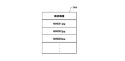
- FIG. 2 is a diagram showing an example of a ground image database for learning;
- FIG. 2 is a diagram illustrating an example of a map image database.
- FIG. 4 is a diagram illustrating an example of a teacher database.
- FIG. 2 is a functional block diagram showing an example of functions realized by the estimation device.
- FIG. 2 is a diagram illustrating an example of an estimation process performed by the estimation device.
- FIG. 2 is a diagram illustrating an example of a ground image database.
- FIG. 2 is a diagram illustrating an example of a map image database.
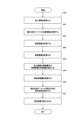
- FIG. 4 is a flow chart illustrating an example of a process executed in the learning device.
- FIG. 4 is a flow chart illustrating an example of a process executed in the learning device.
- FIG. 4 is a flow chart showing an example of processing executed in the estimation device.
- FIG. 13 is a diagram illustrating a loss in learning in the first modified example.
- FIG. 13 is a diagram illustrating a loss in learning in the first modified example.
- FIG. 11 is a functional block diagram showing an example of functions realized by a learning device of modified example 2.
- FIG. 13 is a histogram diagram showing an example of a distribution of teacher data with respect to a pointing direction.
- FIG. 2 is a diagram showing an example of original teacher data;
- FIG. 13 is a diagram illustrating an example of extended teacher data.
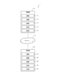
- FIG. 1 is a diagram showing an example of a hardware configuration of a direction estimation system 1 of this embodiment.
- the direction estimation system 1 includes a learning device 10 and an estimation device 20, which are connected to a network N such as the Internet or a LAN.
- a network N such as the Internet or a LAN.
- FIG. 1 shows one learning device 10 and one estimation device 20, there may be a plurality of learning devices 10 and one estimation device 20.
- FIG. 1 shows a case where the learning device 10 and the estimation device 20 are different from each other, but they may be the same device.
- the learning device 10 and the estimation device 20 may belong to different systems.
- the learning device 10 is a computer operated by a user.
- the learning device 10 is a personal computer, a server computer, a portable information terminal (including a tablet computer and a wearable terminal), or a mobile phone (including a smartphone).
- the learning device 10 includes a control unit 11, a memory unit 12, a communication unit 13, an operation unit 14, and a display unit 15.
- the control unit 11 has at least one processor.
- the control unit 11 executes processing according to the programs and data stored in the memory unit 12.
- the memory unit 12 includes a main memory unit and an auxiliary memory unit.
- the main memory unit is a volatile memory such as RAM
- the auxiliary memory unit is a non-volatile memory such as ROM, EEPROM, flash memory, or a hard disk.
- the communication unit 13 is a communication interface for wired or wireless communication, and performs data communication via the network N.
- the operation unit 14 is an input device for performing operations, such as a touch panel or a pointing device such as a mouse, a keyboard, or buttons.
- the display unit 15 is, for example, a liquid crystal display unit or an organic EL display unit. The display unit 15 displays images according to instructions from the control unit 11.
- the estimation device 20 is a computer operated by a user.
- the user of the learning device 10 and the user of the estimation device 20 may be the same or different.
- the estimation device 20 is a personal computer, a server computer, a portable information terminal (including a tablet computer and a wearable terminal), or a mobile phone (including a smartphone).
- the estimation device 20 includes a control unit 21, a memory unit 22, a communication unit 23, an operation unit 24, and a display unit 25.
- the physical configurations of the control unit 21, the memory unit 22, the communication unit 23, the operation unit 24, and the display unit 25 may be similar to those of the control unit 11, the memory unit 12, the communication unit 13, the operation unit 14, and the display unit 15, respectively.
- the programs and data described as being stored in the storage units 12 and 22 may be supplied via the network N.
- the hardware configuration of each of the learning device 10 and the estimation device 20 is not limited to the above example, and various hardware may be applied.
- a reading unit e.g., an optical disk drive or a memory card slot
- an input/output unit e.g., a USB port
- the programs and data stored in the information storage medium may be supplied to each computer via the reading unit or the input/output unit.
- the direction estimation system 1 will be described by taking as an example a case where the direction estimation system 1 is used to estimate the pointing direction of an antenna of a base station included in a mobile communication network. As described above, the direction estimation system 1 can be used to estimate the pointing direction of various objects other than an antenna.
- the pointing direction is the direction that indicates the front direction of the antenna.
- the pointing direction is a direction that has a predetermined relationship with the front direction of the antenna.
- the pointing direction is the front direction of the antenna itself, that is, the direction in which the antenna transmits or receives signals, but the pointing direction is not limited to the front direction of the antenna.
- the pointing direction may be the rear direction of the antenna.
- the pointing direction may be the line of sight.
- the pointing direction may be the direction in which a photographing device such as a camera provided on the drone faces.
- the pointing direction may be the direction in which the windshield of the car faces.
- the pointing direction is not limited to the line of sight.
- the direction estimation system 1 has a learning device 10 and an estimation device 20. Below, we first provide an overview of the learning device 10, and then provide an overview of the estimation device 20.
- FIG 2 is a diagram showing an example of an antenna installation plan P.
- the installation plan P predetermines the location where each antenna should be installed and the direction in which each antenna should point at that location.
- a mobile communication service provider installs antennas in accordance with this installation plan.
- an existing antenna that has been installed in accordance with this installation plan will be referred to as the learning target antenna LA.
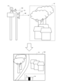
- FIG. 3 is a diagram explaining the learning ground image LGI.
- an operator O uses an image capture device C to capture an image of a feature TF from the position of the learning target antenna LA along the orientation direction AO of the learning target antenna LA, and obtains a learning ground image LGI.
- the learning ground image LGI is an image obtained by capturing an image of a feature TF that exists in a direction according to the orientation direction AO of the learning target antenna LA as viewed from the position of the learning target antenna LA. Details of the learning ground image LGI will be described later.
- the learning device 10 stores a learning ground image database DB1 that stores the learning ground image LGI, the position information of the learning target antenna LA, and the orientation direction AO of the learning target antenna LA in association with each other (see Figure 9).
- FIG. 4 is a diagram explaining the learning reference image LRI.
- the learning reference image LRI is acquired based on the position information of the learning target antenna LA and the map image MI.
- the learning reference image LRI is an image showing a range R of the map image MI with the position of the learning target antenna LA as the base point.
- the learning reference image LRI will be described in detail later.
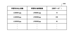
- the pair of learning ground image LGI and learning reference image LRI thus obtained is associated with correct answer data AD indicating the orientation direction AO of the learning target antenna LA in the learning reference image LRI, and is stored as teacher data TD (see FIG. 11).
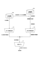
- FIG. 5 is a diagram showing an overview of learning the estimation model M.
- the estimation model M is learned by using the teacher data TD.
- the learned estimation model M thus learned is transmitted to the estimation device 20, which will be described later.
- the estimation device 20 estimates the direction of orientation AO of a newly installed antenna (hereinafter, referred to as an "estimated antenna EA").
- the estimated antenna EA is an antenna different from the already installed learning antenna LA.
- the worker O uses the image capture device C to capture the feature TF from the position of the estimated target antenna EA along the orientation direction AO of the estimated target antenna EA, thereby obtaining a ground image GI.
- the estimation device 20 stores a ground image database DB4 that stores the learning ground image LGI and the position information of the learning antenna LA in association with each other (see FIG. 14).
- a reference image RI is acquired based on the position information of the estimation target antenna EA and the map image MI in the same manner as described with reference to FIG. 4.
- the reference image RI is an image showing a range R of the map image MI starting from the position of the estimation target antenna EA.
- the direction estimation system 1 of this embodiment described above can estimate the pointing direction AO of the antenna EA to be estimated in the reference image RI based on the ground image GI and the reference image RI, making it possible to verify the pointing direction AO of the antenna EA to be estimated.
- the direction estimation system 1 will be described in detail below.
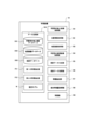
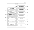
- FIG. 7 is a functional block diagram showing an example of functions realized by the learning device 10.
- the learning device 10 has a data storage unit 100, a ground image acquisition unit for learning 101, a position information acquisition unit 102, a map image acquisition unit 103, a reference image acquisition unit for learning 104, a teacher data generation unit 105, a teacher data acquisition unit 106, a feature extraction unit 107, a combined feature acquisition unit 108, and a learning unit 109.
- the data storage unit 100 is realized by the storage unit 12.
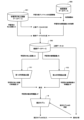
- the ground image acquisition unit for learning 101, the position information acquisition unit 102, the map image acquisition unit 103, the reference image acquisition unit for learning 104, the teacher data generation unit 105, the teacher data acquisition unit 106, the feature extraction unit 107, the combined feature acquisition unit 108, and the learning unit 109 are mainly realized by the control unit 11. These functions are examples of learning functions. In the following description, an example of a learning process of the learning device 10 shown in FIG. 8 may be referred to.
- the data storage unit 100 stores a ground image database DB1, a map image database DB2, a teacher database DB3, a first feature extractor FE1, a second feature extractor FE2, and an estimation model M for learning.
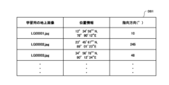
- FIG. 9 is a diagram showing an example of the training ground image database DB1.
- the training ground image database DB1 stores a training ground image LGI, position information of a training target antenna LA, and an orientation direction AO of the training target antenna LA in association with each other.
- the position of the learning target antenna LA is the position of the learning target antenna LA defined in the installation plan P.
- the position of the learning target antenna LA is preferably the same as the position of the learning target antenna LA defined in the installation plan P, but may be a position shifted from the position of the learning target antenna LA defined in the installation plan P.
- the position of the object may be, for example, a position obtained by a surveying means for the object.
- the direction according to the orientation direction AO of the antenna LA to be studied is a direction that has a predetermined relationship with the orientation direction AO of the antenna LA to be studied.
- the direction according to the orientation direction AO of the antenna LA to be studied is the orientation direction AO of the antenna LA to be studied itself. That is, in this embodiment, the direction in which the imaging device C faces (imaging direction CO) is the same as the orientation direction AO of the antenna LA to be studied.
- the direction according to the orientation direction AO of the antenna LA to be studied may be a direction different from the orientation direction AO of the antenna LA to be studied. That is, the imaging direction CO may be a direction different from the orientation direction AO of the antenna LA to be studied.
- the learning ground image LGI shows at least a part of the learning target antenna LA.
- at least a part of the learning target antenna LA is captured in the learning ground image LGI.
- the learning ground image LGI is obtained by photographing the feature TF directly behind and approximately directly above the learning target antenna LA, so that below that, the learning ground image LGI shows a part of the upper surface of the learning target antenna LA. Needless to say, if the photographing position is different, the manner in which the learning target antenna LA is shown in the learning ground image LGI will also differ.
- the target antenna LA shown in the learning ground image LGI has a sign S indicating the orientation direction AO of the target antenna LA.
- the sign S is a rectangular sticker as shown in FIG. 7.
- the sign S is attached to the target antenna LA so that its longitudinal direction is parallel to the orientation direction AO of the target antenna LA.
- the shape of the sign S does not necessarily have to be rectangular, and may be an ellipse, an arrow shape, etc.
- the sign S is not limited to a sticker, and may be, for example, drawn directly on the target antenna LA.
- information derived from the sign S is extracted from the learning ground image LGI as information related to the orientation AO of the target antenna LA, and this information is used for the learning and estimation described below, improving the efficiency of learning and the accuracy of estimation.
- the position information of the target antenna LA is the coordinates indicating the position of the target antenna LA.
- the coordinates indicating the position of the target antenna LA are expressed by latitude and longitude, but may be expressed in a format other than latitude and longitude.
- the orientation direction AO of the target antenna LA stored in the learning ground image database DB1 is obtained by surveying by the worker O, as described above (see Figure 3). As will be described later, the correct answer data AD of the teacher data TD is obtained based on the orientation direction AO of the target antenna LA stored in the learning ground image database DB1.
- FIG. 10 is a diagram showing an example of the map image database DB2. As shown in Fig. 10, the map image database DB2 stores a plurality of map images MI.
- the map image MI is an image obtained by photographing the ground surface from the sky.
- the map image MI can also be said to be an image showing features from the sky.
- the features shown in the map image MI are not limited to the features TF shown in the learning ground image LGI.
- the map image MI is an image obtained by photographing the ground surface directly below from the sky.
- the map image MI is an image showing the ground surface in a planar view.
- the map image MI may be an image of the ground surface photographed diagonally below from the sky.
- the map image MI may be an image showing the ground surface from a bird's-eye view.
- the map image MI is a satellite image, but the map image MI may also be an aerial photograph.
- one map image showing the ground surface of a certain geographical range is divided into multiple map images MI (e.g., a map image showing the ground surface of Tokyo, a map image showing the ground surface of Kanagawa Prefecture, etc.), and these are stored in the map image database DB2.
- the data storage unit 100 may store one map image MI (e.g., a map image showing the ground surface of all of Japan).
- Fig. 11 is a diagram showing an example of the teacher database DB3. As shown in Fig. 11, the teacher database DB3 stores a plurality of teacher data TD. The teacher data TD will be described in detail later.
- the first feature extractor FE1 is a machine learning model used to extract features LGF of a training ground image from the training ground image LGI (see FIG. 8).
- a convolutional neural network (CNN) is used as the first feature extractor FE1, but any machine learning model that extracts features from an image can be used as the first feature extractor FE1.
- the parameters of the first feature extractor FE1 are fixed and are not updated by learning in the learning device 10.
- the feature quantity LGF of the training ground image and the feature quantity LRF of the training reference image are each represented as a multidimensional vector, but may be represented in other formats such as a matrix, an array, or a single numerical value.
- the references to the first feature extractor FE1 and the second feature extractor FE2 do not refer to the concept of feature extraction, but rather to the electronic data generated by that concept.
- the first feature extractor FE1 and the second feature extractor FE2 include a program and parameters.
- the first feature extractor FE1 and the second feature extractor FE2 may refer to either only the program or only the parameters.
- the program included in the first feature extractor FE1 and the second feature extractor FE2 defines the processing content (instructions or calculation formulas) that the computer should execute.
- the estimation model M is a model that estimates the direction of orientation AO of the antenna EA to be estimated based on a pair of a ground image GI and a reference image RI.
- the estimation model M can also be said to be a regression model that regresses the direction of orientation AO of the antenna EA to be estimated based on a pair of a ground image GI and a reference image RI.
- the estimation model M stored in the data storage unit 100 is the estimation model M before learning. That is, the parameters of the estimation model M stored in the data storage unit 100 are initial values. After the learning unit 109 described later starts learning, the data storage unit 100 stores the estimation model M in the middle of learning. After the learning unit 109 ends learning, the data storage unit 100 stores the learned estimation model M.
- various machine learning models such as neural networks can be used.
- the estimation model M receives the combined feature CF obtained based on the feature GF of the ground image and the feature RF of the reference image as input, and outputs the directional direction AO of the antenna EA to be estimated in the reference image RI (see FIG. 13).
- the estimation model M may be a model to which the feature GF of the ground image and the feature RF of the reference image are directly input. In that case, the learning device 10 and the estimation device 20 may not have the combined feature acquisition units 108 and 206 described later.
- the estimation model M may be a model to which the ground image GI and the reference image RI are directly input.
- the learning device 10 and the estimation device 20 may not have the feature extraction units 107 and 205 and the combined feature acquisition units 108 and 206 described later.
- the estimation model M may be a model to which data obtained by combining the ground image GI and the reference image RI is input.
- estimation model M does not refer to the concept of feature extraction, but rather to the electronic data generated by that concept.
- the estimation model M includes a program and parameters. Note that the estimation model M may refer to either only the program or only the parameters.
- the program included in the estimation model M defines the processing content (commands or calculation formulas) that the computer should execute.
- the learning ground image acquisition unit 101 acquires the learning ground image LGI (see FIG. 8). In this embodiment, the ground image acquisition unit 101 acquires the learning ground image LGI from a learning ground image database DB1 stored in the data storage unit 100. Note that the ground image acquisition unit 101 may acquire the learning ground image LGI from a computer other than the learning device 10 or an external information storage medium.
- the position information acquisition unit 102 acquires the position information of the learning target antenna LA (see FIG. 8). In this embodiment, the position information acquisition unit 102 acquires the position information of the learning target antenna LA from a learning ground image database DB1 stored in the data storage unit 100. Note that the position information acquisition unit 102 may acquire the position information of the learning target antenna LA from a computer other than the learning device 10 or an external information storage medium.
- the map image acquisition unit 103 acquires a map image MI (see FIG. 8).
- the map image acquisition unit 103 acquires the map image MI from the map image database DB2 in the data storage unit 100.
- the map image acquisition unit 203 may acquire the map image MI from an external information storage medium or computer.
- the learning reference image acquisition unit 104 acquires a learning reference image LRI based on the position information of the learning target antenna LA and the map image MI (see FIG. 8).
- the learning reference image LRI is an image showing the range R of the map image MI, starting from the position of the learning target antenna LA.
- the range R with the position of the target antenna LA as the base point is a predetermined range that includes the position of the target antenna LA.
- the range R is a predetermined range that has the position of the target antenna LA as the center.
- the center of the range R is not limited to the position of the target antenna LA, and may be, for example, a position that is a predetermined distance away in a predetermined direction from the position of the target antenna LA.
- the learning reference image acquisition unit 104 identifies the position of the learning target antenna LA in the map image MI. Next, the learning reference image acquisition unit 104 identifies a range R based on the position of the learning target antenna LA. In other words, the learning reference image acquisition unit 104 identifies the scale of the map image MI indicated by the learning reference image LRI. Then, the learning reference image acquisition unit 104 acquires a portion of the map image MI that corresponds to the identified range R as the learning reference image LRI.
- the map image MI shown by the learning reference image LRI faces north. That is, in this embodiment, the direction MO in which the map image MI shown by the learning reference image LRI faces is north. In addition, the map image MI shown by the learning reference image LRI may face any direction.
- the teacher data generating unit 105 generates teacher data TD based on a set of the learning ground image LGI and the learning reference image LRI, and the correct answer data AD (see FIG. 8).
- the teacher data generating unit 105 generates the teacher data TD by associating the set of the learning ground image LGI and the learning reference image LRI with the correct answer data AD.
- the teacher data generating unit 105 stores the generated teacher data TD in the teacher database DB3 of the data storage unit 100.
- the correct answer data AD indicates the orientation direction AO of the learning target antenna LA in the learning reference image LRI (see FIG. 5).
- the correct answer data AD can also be said to be label data for the learning ground image LGI and the learning reference image LRI.
- the correct answer data AD can be said to be data indicating a true value.
- the teacher data generating unit 105 generates the correct answer data AD based on the orientation direction of the learning target antenna LA acquired from the learning ground image database DB1 (see FIG. 8).
- the correct answer data AD indicates the orientation direction AO itself of the learning target antenna LA in the learning reference image LRI, so the teacher data generating unit 105 may use the orientation direction of the learning target antenna LA acquired from the learning ground image database DB1 as the correct answer data AD as it is.
- the correct answer data AD indicates a direction that has a predetermined relationship with the orientation direction AO of the learning target antenna LA in the learning reference image LRI.
- the correct answer data AD indicates the orientation direction AO of the learning target antenna LA in the learning reference image LRI itself, but the correct answer data AD may indicate a direction different from the orientation direction AO of the learning target antenna LA in the learning reference image LRI.
- the correct answer data AD may indicate the shooting direction CO.
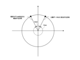
- the correct answer data AD is represented by an azimuth angle Az of a direction that has a predetermined relationship with the orientation direction AO of the learning target antenna LA in the learning reference image LRI (see FIG. 5).
- the azimuth angle Az is based on the orientation direction MO (i.e., north) of the map image MI shown in the learning reference image LRI.
- the azimuth angle Az is the angle between the orientation direction MO of the map image MI shown in the learning reference image LRI and a direction that has a predetermined relationship with the orientation direction AO of the learning target antenna LA in the learning reference image LRI (in this embodiment, the orientation direction AO itself of the learning target antenna LA in the learning reference image LRI).
- the azimuth angle Az may be based on a direction other than the orientation direction MO of the map image MI shown in the learning reference image LRI.
- the orientation direction MO of the map image MI shown in the learning reference image LRI is north
- the azimuth angle Az may be based on the south.
- the ground image acquisition unit 101, the location information acquisition unit 102, the map image acquisition unit 103, and the learning reference image acquisition unit 104 are realized by the learning device 10, these functions may be realized by a device other than the learning device 10.
- the generation of the teacher data TD, and therefore the generation of the teacher database DB3 may be performed by a device other than the learning device 10.
- the teacher data acquisition unit 106 acquires a plurality of teacher data TD (see FIG. 8).
- the teacher data acquisition unit 106 acquires the plurality of teacher data TD from the teacher database DB3 of the data storage unit 100.
- the teacher data acquisition unit 106 may acquire the plurality of teacher data TD from an external information storage medium or computer.
- the feature extraction unit 107 extracts the feature amount LGF of the training ground image from the training ground image LGI based on the first feature extractor FE1, and extracts the feature amount LRF of the training reference image from the training reference image LRI based on the second feature extractor FE2 (see FIG. 8). Specifically, the feature extraction unit 107 inputs the training ground image LGI to the first feature extractor FE1, and obtains the feature amount LGF of the training ground image output from the first feature extractor FE1. Similarly, the feature extraction unit 107 inputs the training reference image LRI to the second feature extractor FE2, and obtains the feature amount LRF of the training reference image output from the second feature extractor FE2.
- the combined feature acquisition unit 108 acquires a training combined feature LCF based on the features LGF of the training ground image and the features LRF of the training reference image (see FIG. 8). Specifically, the combined feature acquisition unit 108 acquires a training combined feature LCF by combining the features LGF of the training ground image and the features LRF of the training reference image. Combination can also be called concatenation.
- the training combined feature LCF is a vector whose dimensionality is the sum of the dimensionality of the features LGF of the training ground image and the dimensionality of the features LRF of the training reference image.
- the learning unit 109 executes learning of the estimation model M based on each of the multiple pieces of teacher data TD (see FIG. 8).
- the learning unit 109 calculates the loss based on the output of the estimation model M based on the training ground image LGI and the training reference image LRI, and the ground truth data AD. In this embodiment, the learning unit 109 calculates the loss based on the output of the estimation model M when the training combined feature LCF is input, and the ground truth data AD.
- the loss indicates the difference between the direction indicated by the output of the estimation model M based on the training ground image LGI and the training reference image LRI, and the direction indicated by the ground truth data AD.
- the loss is sometimes called a loss function, referring to the function itself that calculates the numerical value of the loss.
- Various losses can be used, such as the mean squared error (MSE), mean absolute error (MAE), or mean squared logarithmic error (MSLE).
- the learning unit 109 performs learning of the estimation model M based on the calculated loss.
- Learning of the estimation model M means adjusting the parameters of the estimation model M.
- the learning unit 109 performs learning of the estimation model M so as to reduce the loss.
- various algorithms such as backpropagation, gradient descent, or Adam may be used.
- the learning unit 109 repeats learning of the estimated model M until the loss becomes sufficiently small (for example, the loss becomes less than a threshold value).
- the learning unit 109 may repeat learning using the same teacher database DB3 until the loss becomes sufficiently small, or may learn using a new teacher database DB3. If the loss becomes sufficiently small during learning, learning may end at that point.
- the learning unit 109 may end learning after repeating learning a predetermined number of times, even if the loss is not sufficiently small.
- FIG. 12 is a functional block diagram showing an example of a function realized by the estimation device 20.
- the estimation device 20 has a data storage unit 200, a ground image acquisition unit 201, a position information acquisition unit 202, a map image acquisition unit 203, a reference image acquisition unit 204, a feature extraction unit 205, a combined feature acquisition unit 206, and an estimation unit 207.
- the data storage unit 200 is realized by the storage unit 22.
- the ground image acquisition unit 201, the position information acquisition unit 202, the map image acquisition unit 203, the reference image acquisition unit 204, the feature extraction unit 205, the combined feature acquisition unit 206, and the estimation unit 207 are mainly realized by the control unit 21.
- These functions are an example of an estimation function.
- an example of an estimation process of the estimation device 20 shown in FIG. 13 may be referred to.
- the data storage unit 200 stores a ground image database DB4, a map image database DB5, a first feature extractor FE1, a second feature extractor FE2, and an estimation model M.
- [Ground image database] 14 is a diagram showing an example of the ground image database DB4.
- the ground image database DB4 stores the ground image GI and the position information of the estimation target antenna EA in association with each other. Note that, since the estimation device 20 estimates the pointing direction AO of the estimation target antenna EA, the ground image database DB4 does not store the pointing direction AO of the estimation target antenna EA, unlike the learning ground image database DB1.
- the ground image GI is an image obtained by photographing a feature TF that exists in a direction corresponding to the orientation direction AO of the estimated target antenna EA as viewed from the position of the estimated target antenna EA. Details of the ground image GI are the same as those of the learning ground image LGI, so a description will be omitted (see Figure 3).
- FIG. 15 is a diagram showing an example of the map image database DB5.
- the map image database DB5 is the same as the map image database DB2 (see Fig. 10). Therefore, a description of the map image database DB5 will be omitted. Note that the map image database DB5 may be different from the map image database DB2.
- the first feature extractor FE1 and the second feature extractor FE2 are the same as those stored in the data storage unit 100 of the learning device 10, and therefore a description thereof will be omitted.
- the data storage unit 200 of the estimation device 20 may store a first feature extractor FE1 and a second feature extractor FE2 different from those stored in the data storage unit 100 of the learning device 10.
- the data storage unit 200 stores an estimation model M that has been trained by the learning device 10. That is, the estimation model M stored in the data storage unit 200 is a trained model in which the relationship between a set of a training ground image LGI and a training reference image LRI, and the supervised data AD has been trained.
- the ground image acquisition unit 201 acquires a ground image GI (see FIG. 13).
- the ground image acquisition unit 201 acquires the ground image GI from a ground image database DB4 stored in the data storage unit 200.
- the ground image acquisition unit 201 may acquire the ground image GI from a computer other than the estimation device 20 or an external information storage medium.
- the position information acquisition unit 202 acquires the position information of the estimation target antenna EA (see FIG. 13). In this embodiment, the position information acquisition unit 202 acquires the position information of the estimation target antenna EA from the ground image database DB4 stored in the data storage unit 100. Note that the position information acquisition unit 202 may acquire the position information of the estimation target antenna EA from another computer other than the estimation device 20 or an external information storage medium.
- the map image acquisition unit 203 acquires a map image MI (see FIG. 13).
- the map image acquisition unit 203 acquires the map image MI from the map image database DB5 in the data storage unit 200.
- the map image acquisition unit 203 may acquire the map image MI from an external information storage medium or computer.
- the reference image acquisition unit 204 acquires a reference image RI based on the position information of the estimation target antenna EA and the map image MI (see FIG. 13).
- the reference image RI is an image showing a range R in the map image MI with the position of the estimation target antenna EA as the base point.
- the details of the reference image RI are the same as those of the learning reference image LRI (see FIG. 4), and therefore a description thereof will be omitted.
- the details of the reference image acquisition unit 204 are the same as those of the learning reference image acquisition unit 104, and therefore a description thereof will be omitted.
- the feature extraction unit 205 extracts a feature amount GF of a ground image from the ground image GI based on the first feature extractor FE1, and extracts a feature amount RF of a reference image from the reference image RI based on the second feature extractor FE2 (see FIG. 13). Specifically, the feature extraction unit 205 inputs the ground image GI to the first feature extractor FE1, and obtains the feature amount GF of the ground image output from the first feature extractor FE1. Similarly, the feature extraction unit 205 inputs the reference image RI to the second feature extractor FE2, and obtains the feature amount RF of the reference image output from the second feature extractor FE2.
- the combined feature acquisition unit 206 acquires a combined feature CF based on the feature GF of the ground image and the feature RF of the reference image (see FIG. 13). Specifically, the combined feature acquisition unit 206 acquires a combined feature CF by combining the feature GF of the ground image and the feature RF of the reference image.
- the estimation unit 207 executes estimation of the orientation direction AO of the antenna EA to be estimated based on a set of the estimation model M, the ground image GI, and the reference image RI (see FIG. 13). Specifically, in this embodiment, the estimation unit 207 acquires an estimation result based on the output of the estimation model M when the combined feature CF is input. The estimation result is an estimated value of the orientation direction AO of the antenna EA to be estimated in the reference image RI. Note that, in this embodiment, the estimation unit 207 acquires the output of the estimation model M as the estimation result as it is.
- the output of the estimation model M indicates an estimated value of the orientation direction AO of the estimation target antenna EA in the reference image RI (see FIG. 6). Specifically, the output of the estimation model M indicates an estimated value of a direction that has a predetermined relationship with the orientation direction AO of the estimation target antenna EA in the reference image RI. Note that in this embodiment, the output of the estimation model M indicates an estimated value of the orientation direction AO itself of the estimation target antenna EA in the reference image RI. The output of the estimation model M may indicate an estimated value of a direction different from the orientation direction AO of the estimation target antenna EA in the reference image RI. For example, the output of the estimation model M may indicate the shooting direction CO. In that case, the estimation unit 207 may calculate an estimated value of the orientation direction AO of the estimation target antenna EA in the reference image RI from the output of the estimation model M based on the predetermined relationship.
- the output of the estimation model M is represented by an estimated value of the azimuth angle Az of a direction that has a predetermined relationship with the orientation direction AO of the estimated target antenna EA in the reference image RI (see FIG. 3).
- the azimuth angle Az is based on the direction MO (i.e., north) of the map image MI shown in the reference image RI.
- the azimuth angle Az is the angle between the direction MO of the map image MI shown in the reference image RI and a direction that has a predetermined relationship with the orientation direction AO of the estimated target antenna EA in the reference image RI (the orientation direction AO of the estimated target antenna EA in the reference image RI itself in this embodiment).
- the azimuth angle Az may be based on a direction other than the orientation direction MO of the map image MI shown in the reference image RI.
- the orientation direction MO of the map image MI shown in the reference image RI is north
- the azimuth angle Az may be based on the south.
- the output of the estimation model M is represented by the estimated value of the azimuth angle Az itself, but it may also be represented by information indicating the estimated value of the azimuth angle Az. That is, the output of the estimation model M may be represented by a numerical value that can be converted into an estimated value of the azimuth angle Az. For example, the output of the estimation model M may be represented by a numerical value greater than or equal to 0 and less than 1. In that case, the estimation unit 207 may multiply the output of the estimation model M by 360 (2 ⁇ when radians are used as the unit of angle) to calculate the estimated value of the azimuth angle Az.
- the pointing direction AO of the antenna EA to be estimated in the reference image RI can be estimated using the ground image GI and the reference image RI, making it possible to verify the pointing direction AO of the antenna EA to be estimated with little effort.
- the estimation device 20 of this embodiment position information of the antenna EA to be estimated and a map image MI are acquired, and a reference image RI is acquired based on these.
- the estimation device 20 of this embodiment can omit the process of estimating the position of the antenna EA to be estimated, and reduce the load of the process of estimating the pointing direction AO of the antenna EA to be estimated.
- Processing Executed in the Direction Estimation System of the Present Embodiment The following describes the processes executed in the direction estimation system 1 of this embodiment. First, the processes executed in the learning device 10 will be described, and then the processes executed in the estimation device 20 will be described.
- FIGS 16A and 16B are flow diagrams showing an example of processing executed in the learning device 10.
- the processing shown in Figures 16A and 16B is executed by the control unit 11 operating in accordance with a program stored in the storage unit 12.
- the processing described below is an example of processing executed by the functional blocks shown in Figure 7. It is assumed that the ground image database DB1, map image database DB2, teacher database DB3, and estimation model M for learning are stored in advance in the storage unit 12.
- the control unit 11 acquires a learning ground image LGI (S100).
- the control unit 11 acquires position information of the learning target antenna LA (S101).
- the learning ground image LGI and the position information of the learning target antenna LA are acquired from the learning ground image database DB1 and the map image database DB2, respectively.
- the control unit 11 acquires a map image MI (S102). In S102, the control unit 11 acquires the map image MI from the map image database DB2. The control unit 11 acquires a reference image LRI for learning (S103). In S103, the control unit 11 first identifies the position of the learning target antenna LA in the map image MI, and identifies a range R that has the position of the learning target antenna LA as its base point. The control unit 11 then acquires the portion of the map image MI that corresponds to the identified range R as the reference image LRI for learning.
- the control unit 11 generates teacher data TD based on the set of learning ground images LGI and learning reference images LRI, and the correct answer data AD (S104). In S104, the control unit 11 stores the generated teacher data TD in the teacher database DB3. If the control unit 11 determines not to end the generation of the teacher data TD (S105; N), it repeats the processes from S100 to S104. If the control unit 11 determines to end the generation of the teacher data TD (S105; Y), it proceeds to the processes from S107 onwards shown in FIG. 16B.
- the control unit 11 acquires teacher data TD including the learning ground image LGI, the learning reference image LRI, and the correct answer data AD (S107).
- the control unit 11 acquires each of the multiple teacher data TD stored in the teacher database DB3.
- the control unit 11 extracts the feature quantity LGF of the training ground image from the training ground image LGI, and extracts the feature quantity LRF of the training reference image from the training reference image LRI (S108).
- the control unit 11 obtains the training combined feature quantity LCF based on the feature quantity LGF of the training ground image and the feature quantity LRF of the training reference image (S109). In S109, the control unit 11 combines the feature quantity LGF of the training ground image and the feature quantity LRF of the training reference image.
- the control unit 11 executes a learning process for the estimation model M (S110).
- the control unit 11 calculates a loss based on the output of the estimation model M based on the learning ground image LGI and the learning reference image LRI, and on the ground truth data AD, and executes a learning process for the estimation model M based on the calculated loss.
- the control unit 11 determines whether or not to end the learning process of the estimation model M (S111).
- the learning of the estimation model M can be ended at any timing, and may be ended when the loss becomes sufficiently small, or at another timing. If the control unit 11 determines not to end the learning process (S111; N), it repeats the processes from S107 to S110. If the control unit 11 determines to end the learning process (S111; Y), it transmits the learned estimation model M to the estimation device 20 (S112) and ends this process.
- control unit 21 first acquires a learning ground image GI (S100) and then acquires a learning reference image RI (S101 to S103), but the control unit 21 may first acquire a learning reference image RI and then acquire a learning ground image GI. In addition, the control unit 21 may acquire the position information of the learning target antenna LA after acquiring the map image MI.
- Fig. 17 is a flow diagram showing an example of processing executed in the estimation device 20.
- the processing shown in Fig. 17 is executed by the control unit 21 operating in accordance with a program stored in the storage unit 22.
- the processing described below is an example of processing executed by the functional blocks shown in Fig. 12. It is assumed that the ground image database DB4, the map image database DB5, and the estimation model M are stored in advance in the storage unit 22.
- the control unit 21 acquires a ground image GI (S200).
- the control unit 21 acquires position information of the estimated target antenna EA (S201).
- the ground image GI and the position information of the estimated target antenna EA are acquired from the ground image database DB4 and the map image database DB5, respectively.
- the control unit 21 acquires a map image MI (S202). In S202, the control unit 21 acquires the map image MI from the map image database DB5. The control unit 21 acquires a reference image RI (S203). In S203, the control unit 21 first identifies the position of the estimated target antenna EA in the map image MI, and identifies a range R that has the position of the estimated target antenna EA as its base point. The control unit 21 then acquires a portion of the map image MI that corresponds to the identified range R as the reference image RI.
- the control unit 21 extracts ground image features GF from the ground image GI, and extracts reference image features RF from the reference image RI (S204).
- the control unit 21 obtains combined features CF based on the ground image features GF and the reference image features RF (S205).
- the control unit 11 obtains combined features CF by combining the learning ground image LGI and the learning reference image LRI.
- the control unit 21 executes an estimation process for the orientation direction AO of the antenna EA to be estimated (S206).
- the control unit 21 inputs the combined feature CF to the estimation model M and obtains the output of the estimation model M. Then, the control unit 21 obtains the estimation result based on the output of the estimation model M.
- the control unit 21 causes the display unit 25 to display the estimation result obtained in S206 (S207), and ends this process.
- control unit 21 first acquires the ground image GI (S200) and then acquires the reference image RI (S201 to S203), but the control unit 21 may first acquire the reference image RI and then acquire the ground image GI. In addition, the control unit 21 may acquire the position information of the estimation target antenna EA after acquiring the map image MI.
- examples of losses used by the learning unit 109 of the learning device 10 include the root mean square error, the mean absolute error, and the root mean square logarithmic error, but losses other than these may also be used by the learning unit 109.
- the loss indicates the difference between the direction indicated by the output of the estimation model M based on the training ground image LGI and the training reference image LRI, and the direction indicated by the ground truth data AD.
- the difference between the direction indicated by the output of the estimation model M and the direction indicated by the ground truth data AD corresponds to the angle between the direction indicated by the output of the estimation model M and the direction indicated by the ground truth data AD.
- Fig. 18 is a diagram for explaining the loss in learning in the first modified example.
- the angle between the direction indicated by the output of the estimation model M and the direction indicated by the correct answer data AD includes a minor angle A sub and a dominant angle A sup .
- the minor angle A sub is the smaller angle between the direction indicated by the output of the estimation model M and the direction indicated by the correct answer data AD.
- the dominant angle A sup is the larger angle between the direction indicated by the output of the estimation model M and the direction indicated by the correct answer data AD.
- the loss mentioned in the embodiment indicates the superior angle A sup between the direction indicated by the output of the estimation model M based on the training ground image LGI and the training reference image LRI and the direction indicated by the ground truth data AD.
- the loss used in the learning unit 109 of the first modification indicates the minor angle A sub between the direction indicated by the output of the estimation model M based on the learning ground image LGI and the learning reference image LRI, and the direction indicated by the ground truth data AD.
- the loss used in the learning unit 109 of the first modification is expressed by the following formula 1. Note that the expression format of the loss used in the learning unit 109 of the first modification is not limited to the formula 1.
- L is the loss
- n is the number of training data TD
- yi is the angle of the direction indicated by the correct answer data AD
- ypred is the angle of the direction indicated by the output of the estimation model M based on the training ground image LGI and the training reference image LRI.
- the loss indicates the minor angle A sub between the direction indicated by the output of the estimation model M based on the learning ground image LGI and the learning reference image LRI, and the direction indicated by the ground answer data AD. This makes the loss value smaller, making it easier for the loss to converge and improving learning efficiency.
- [5-2. Modification 2] 19 is a functional block diagram showing an example of functions realized by the learning device 10 of Modification 2.
- the learning device 10 of Modification 2 differs from the learning device 10 of the embodiment in that it has an extended teacher data generating unit 106a. Note that, among the functions of the learning device 10 of Modification 2, functions other than the extended teacher data generating unit 106a are similar to those of the embodiment, and therefore description thereof will be omitted.
- FIG. 20 is a histogram diagram showing an example of the distribution of teacher data TD with respect to the pointing direction AO.
- the horizontal axis of FIG. 20 is the azimuth angle Az representing the pointing direction AO of the learning target antenna LA in the learning reference image LRI.
- the vertical axis of FIG. 20 is the number of teacher data TD.
- Each hatched bar graph in FIG. 20 indicates the number of teacher data TD only for each pointing direction AO.
- Each black bar graph in FIG. 20 indicates the total number of teacher data TD and extended teacher data ATD (described later) for each pointing direction.
- the target antenna LA is installed in accordance with the installation plan P (see Figure 2).
- the pointing direction AO of the target antenna LA which is determined in the installation plan P, may be biased.
- the pointing direction AO of the target antenna LA may be biased.
- a bias occurs in the number of teacher data TD for each pointing direction AO.
- the number of teacher data TD in which the pointing direction AO of the learning target antenna LA in the learning reference image LRI indicated by the correct answer data AD is a direction with an azimuth angle of 100° (first direction) is greater than the number of teacher data TD in which the pointing direction AO of the learning target antenna LA in the learning reference image LRI indicated by the correct answer data AD is a direction with an azimuth angle of 10° (second direction different from the first direction).
- the multiple teacher data TD can be said to be unbalanced data. Note that the above azimuth angle values are just examples.
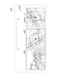
- FIG. 21 is a diagram showing an example of original teacher data OTD.
- FIG. 22 is a diagram showing an example of extended teacher data ATD.
- the extended teacher data generation unit 106a rotates the learning reference image LRI of the original teacher data OTD (see FIG. 21), in which the direction at an azimuth angle of 100° is the correct answer, by -90° to generate extended teacher data ATD (see FIG. 22), in which the direction at an azimuth angle of 10° is the correct answer.
- the extended teacher data generation unit 106a rotates the learning reference image LRI of the original teacher data OTD to generate extended teacher data ATD.
- the extended teacher data generating unit 106a generates extended teacher data ATD based on the original teacher data OTD, using teacher data TD in which the orientation direction AO of the learning target antenna LA in the learning reference image LRI indicated by the correct answer data AD is a direction with an azimuth angle of 100°.
- the extended teacher data ATD includes an extended ground image AGI, an extended reference image ARI, and extended correct answer data AAD.
- the extended ground image AGI is a learning ground image LGI included in the original teacher data OTD.
- the extended reference image ARI is an image obtained by rotating the learning reference image LRI included in the original teacher data OTD.
- the extended correct answer data AAD indicates the direction of an azimuth angle of 10°, which is the pointing direction AO of the learning target antenna LA in the extended reference image ARI.
- the learning unit 109 of the second modified example performs learning of the estimation model M further based on the extended teacher data ATD.
- the learning process itself in the learning unit 109 of the second modified example is similar to the learning process in the learning unit 109 of the embodiment, so a description thereof will be omitted.
- the extended teacher data ATD is generated and used for learning, which makes it possible to even out the bias in the number of teacher data TD for the directional direction AO (see FIG. 16), thereby making it possible to prevent bias in learning.
- an image obtained by photographing the ground surface from the sky with a so-called passive sensor, such as a satellite image or an aerial photograph has been given as an example of the map image MI
- the map image MI may be an image obtained by photographing the ground surface from the sky with a so-called active sensor, such as a SAR image (synthetic aperture radar image).
- the map image MI may be an image obtained by combining a satellite image or an aerial photograph with a SAR image.
- the map image MI may be an image in which the pixel value of each pixel of the SAR image is weighted by a predetermined weight with respect to the pixel value of each pixel of the satellite image or the aerial photograph.
- the SAR image may be, for example, an InSAR image (interferometric synthetic aperture radar image), an ISAR image (inverse synthetic aperture radar image), or the like.
- the direction estimation system 1 may also perform learning and estimation based on a second map image (such as a SAR image) which is an image obtained by photographing the ground surface from the sky using an active sensor, in addition to a first map image (such as a satellite image or aerial photograph) which is an image obtained by photographing the ground surface from the sky using a passive sensor.
- a second map image such as a SAR image
- a first map image such as a satellite image or aerial photograph
- the learning device 10 may perform learning of the estimation model M based on a plurality of teacher data each including a set of a learning ground image LGI, a first learning reference image showing a range in the first map image with the position of the learning target antenna LA as a base point, and a second learning reference image in the second map image showing a range in the second map image with the position of the learning target antenna LA as a base point, and correct answer data.
- a plurality of teacher data each including a set of a learning ground image LGI, a first learning reference image showing a range in the first map image with the position of the learning target antenna LA as a base point, and a second learning reference image in the second map image showing a range in the second map image with the position of the learning target antenna LA as a base point, and correct answer data.
- the estimation device 20 may also estimate the pointing direction AO of the antenna EA to be estimated based on a ground image GI, a first reference image showing a range in the first map image with the position of the antenna EA to be estimated as a base point, a second reference image showing a range in the second map image with the position of the antenna EA to be estimated as a base point, and an estimation model M.
- the direction estimation system 1 of variant 3 described above performs learning and estimation based on images obtained by photographing the ground surface from the sky using an active sensor, so it is possible to take into account the surface shapes of objects on the ground and perform direction estimation with higher accuracy.
- the direction estimation system 1 of the present disclosure may be configured as follows.
- a first image acquisition means for acquiring a first image which is an image obtained by photographing a feature present in a direction corresponding to a pointing direction of the object to be estimated as viewed from a position of the object to be estimated;
- a position information acquisition means for acquiring position information of the estimation target object;
- a map image acquisition means for acquiring a map image obtained by photographing the ground surface from the sky;
- a second image acquisition means for acquiring a second image indicating a range having a base point at the position of the object to be estimated from the map image based on position information of the object to be estimated and the map image;
- an estimation means for estimating the orientation direction of the estimation target object based on a trained estimation model that has learned the relationship between a first training image, which is an image obtained by photographing a feature existing in a direction corresponding to the orientation direction of the training target object as viewed from the position of the training target object, and a second training image, which is one of the map images and indicates a range starting from the position of
- the first image shows at least a portion of the object to be estimated; the first training image shows at least a portion of the training object; the object to be estimated shown in the first image has a marker indicating a direction in which the object to be estimated is directed; the learning object shown in the first learning image has a marker indicating a direction of orientation of the learning object;
- a direction estimation system according to claim 1 or 2.
- the trained estimation model is Calculating a loss based on an output of the estimation model based on the set of the first training image and the second training image and the ground truth data, and performing training of the estimation model based on the loss; It is generated by The loss indicates an angle that is a minor angle between a direction indicated by an output of the estimation model based on the set of the first training image and the second training image and a direction indicated by the ground truth data.
- a direction estimation system according to any one of claims 1 to 3.
- the method further includes an extended teacher data generating means for generating extended teacher data based on the original teacher data, the original teacher data being the teacher data in which the orientation direction of the estimation target object in the second learning image indicated by the correct answer data is a first direction,
- the extended teacher data includes a set of a first extended learning image, which is the first learning image included in the original teacher data, and a second extended learning image obtained by rotating the second learning image included in the original teacher data, and extended correct answer data indicating a second direction different from a first direction, which is a pointing direction of the estimation target object in the second extended learning image
- the learning means executes learning of the estimation model further based on the extended teacher data.
- the learning means calculates a loss based on an output of the estimation model based on a set of the first learning image and the second learning image and the ground truth data, and executes learning of the estimation model based on the loss;
- the loss indicates an angle that is a minor angle between a direction indicated by an output of the estimation model based on the set of the first training image and the second training image and a direction indicated by the ground truth data.
- a learning system according to any one of (5) to (7).
- the first training image shows at least a portion of the training object;
- the learning object shown in the first learning image has a marker indicating a direction of orientation of the learning object;
- a learning system according to any one of (5) to (8).
Landscapes
- Engineering & Computer Science (AREA)
- Software Systems (AREA)
- Computer Networks & Wireless Communication (AREA)
- Signal Processing (AREA)
- Theoretical Computer Science (AREA)
- Computer Vision & Pattern Recognition (AREA)
- Evolutionary Computation (AREA)
- Medical Informatics (AREA)
- Data Mining & Analysis (AREA)
- Physics & Mathematics (AREA)
- Computing Systems (AREA)
- General Engineering & Computer Science (AREA)
- General Physics & Mathematics (AREA)
- Mathematical Physics (AREA)
- Artificial Intelligence (AREA)
- Image Analysis (AREA)
Abstract
Description
図1は、本実施形態の方向推定システム1のハードウェア構成の一例を示す図である。図1に示すように、方向推定システム1は、学習装置10及び推定装置20を含み、これらは、インターネット又はLAN等のネットワークNに接続される。なお、図1では、学習装置10及び推定装置20を1台ずつ示しているが、これらは複数台あってもよい。また、図1では、学習装置10及び推定装置20がそれぞれ異なる場合を示しているが、これらは同一の装置であってもよい。更に、学習装置10及び推定装置20は、互いに異なるシステムに属していてもよい。
以下、本実施形態の方向推定システム1の概要を説明する。本実施形態では、移動体通信ネットワークに含まれる基地局のアンテナの指向方向を推定するのに方向推定システム1を用いる場合を例に挙げて、方向推定システム1を説明する。なお、前述の通り、方向推定システム1は、アンテナ以外にも、様々なオブジェクトの指向方向を推定するのに利用可能である。
学習装置10では、アンテナの指向方向を推定するための推定モデルMの学習が行われる。学習装置10では、推定モデルMを学習するための教師データTDが生成され、そして、生成された教師データTDに基づいて推定モデルMの学習が行われる(図5参照)。
推定装置20では、新たに設置されたアンテナ(以降、「推定対象アンテナEA」という。)の指向方向AOが推定される。推定対象アンテナEAは、既設である学習対象アンテナLAとは異なるアンテナである。
以下では、本実施形態の方向推定システム1で実現される機能を説明する。まず、学習装置10で実現される機能を説明し、次に、推定装置20で実現される機能を説明する。
図7は、学習装置10で実現される機能の一例を示す機能ブロック図である。図7に示すように、学習装置10は、データ記憶部100、学習用の地上画像取得部101、位置情報取得部102、地図画像取得部103、学習用の参照画像取得部104、教師データ生成部105、教師データ取得部106、特徴抽出部107、結合特徴量取得部108及び学習部109を有する。データ記憶部100は、記憶部12により実現される。学習用の地上画像取得部101、位置情報取得部102、地図画像取得部103、学習用の参照画像取得部104、教師データ生成部105、教師データ取得部106、特徴抽出部107、結合特徴量取得部108及び学習部109は、制御部11を主として実現される。これらの機能は、学習機能の一例である。なお、以下の説明では、図8に示す学習装置10の学習処理の一例を参照することがある。
データ記憶部100は、学習用の地上画像データベースDB1、地図画像データベースDB2、教師データベースDB3、第1の特徴抽出器FE1、第2の特徴抽出器FE2及び推定モデルMを記憶する。
図9は、学習用の地上画像データベースDB1の一例を示す図である。図9に示すように、学習用の地上画像データベースDB1は、学習用の地上画像LGIと、学習対象アンテナLAの位置情報と、学習対象アンテナLAの指向方向AOと、を互いに関連付けて格納する。
図10は、地図画像データベースDB2の一例を示す図である。図10に示すように、地図画像データベースDB2は、複数の地図画像MIを格納する。
図11は、教師データベースDB3の一例を示す図である。図11に示すように、教師データベースDB3は、複数の教師データTDを格納する。教師データTDの詳細については後述する。
第1の特徴抽出器FE1は、学習用の地上画像LGIから、学習用の地上画像の特徴量LGFを抽出するために用いられる機械学習モデルである(図8参照)。本実施形態では、第1の特徴抽出器FE1として、畳み込みニューラルネットワーク(CNN:Convolutional Neural Network)を用いるものとするが、第1の特徴抽出器FE1としては、画像から特徴量を抽出する任意の機械学習モデルが利用可能である。なお、第1の特徴抽出器FE1のパラメータは固定であり、学習装置10での学習では更新されない。
第2の特徴抽出器FE2は、学習用の参照画像LRIから、学習用の参照画像の特徴量LRFを抽出するために用いられる機械学習モデルである(図8参照)。第2の特徴抽出器FE2としては、画像から特徴量を抽出する任意の機械学習モデルが利用可能である。本実施形態では、第2の特徴抽出器FE2として、第1の特徴抽出器と同様、畳み込みニューラルネットワークを用いるものとする。なお、第1の特徴抽出器FE1と第2の特徴抽出器FE2との間ではパラメータは共有されない。また、第2の特徴抽出器FE2のパラメータは固定であり、学習装置10での学習では更新されない。
推定モデルMは、地上画像GI及び参照画像RIの組に基づいて、推定対象アンテナEAの指向方向AOを推定するモデルである。推定モデルMは、地上画像GI及び参照画像RIの組に基づいて、推定対象アンテナEAの指向方向AOを回帰する回帰モデルであるということもできる。データ記憶部100に記憶された推定モデルMは、学習前の推定モデルMである。すなわち、データ記憶部100に記憶された推定モデルMのパラメータは初期値である。後述の学習部109が学習を開始した後は、データ記憶部100は、学習途中の推定モデルMを記憶する。学習部109が学習を終了した後は、データ記憶部100は、学習済みの推定モデルMを記憶する。推定モデルMとしては、ニューラルネットワーク等、種々の機械学習モデルが利用可能である。
学習用の地上画像取得部101は、学習用の地上画像LGIを取得する(図8参照)。本実施形態では、地上画像取得部101は、データ記憶部100に記憶された学習用の地上画像データベースDB1から、学習用の地上画像LGIを取得する。なお、地上画像取得部101は、学習装置10以外の他のコンピュータ又は外部の情報記憶媒体から学習用の地上画像LGIを取得してもよい。
位置情報取得部102は、学習対象アンテナLAの位置情報を取得する(図8参照)。本実施形態では、位置情報取得部102は、データ記憶部100に記憶された学習用の地上画像データベースDB1から、学習対象アンテナLAの位置情報を取得する。なお、位置情報取得部102は、学習装置10以外の他のコンピュータ又は外部の情報記憶媒体から学習対象アンテナLAの位置情報を取得してもよい。
地図画像取得部103は、地図画像MIを取得する(図8参照)。本実施形態では、地図画像取得部103は、データ記憶部100の地図画像データベースDB2から、地図画像MIを取得する。地図画像取得部203は、外部の情報記憶媒体又はコンピュータから地図画像MIを取得してもよい。
学習用の参照画像取得部104は、学習対象アンテナLAの位置情報及び地図画像MIに基づいて、学習用の参照画像LRIを取得する(図8参照)。
教師データ生成部105は、学習用の地上画像LGI及び学習用の参照画像LRIの組と、正解データADと、に基づいて、教師データTDを生成する(図8参照)。教師データ生成部105は、学習用の地上画像LGI及び学習用の参照画像LRIの組と、正解データADと、を互いに関連付けることにより、教師データTDを生成する。教師データ生成部105は、生成した教師データTDをデータ記憶部100の教師データベースDB3に記憶する。
教師データ取得部106は、複数の教師データTDを取得する(図8参照)。本実施形態では、教師データ取得部106は、データ記憶部100の教師データベースDB3から、複数の教師データTDを取得する。教師データ取得部106は、外部の情報記憶媒体又はコンピュータから複数の教師データTDを取得してもよい。
特徴抽出部107は、第1の特徴抽出器FE1に基づいて、学習用の地上画像LGIから学習用の地上画像の特徴量LGFを抽出するとともに、第2の特徴抽出器FE2に基づいて、学習用の参照画像LRIから学習用の参照画像の特徴量LRFを抽出する(図8参照)。具体的には、特徴抽出部107は、第1の特徴抽出器FE1に学習用の地上画像LGIを入力し、第1の特徴抽出器FE1から出力される学習用の地上画像の特徴量LGFを取得する。同様に、特徴抽出部107は、第2の特徴抽出器FE2に学習用の参照画像LRIを入力し、第2の特徴抽出器FE2から出力される学習用の参照画像の特徴量LRFを取得する。
結合特徴量取得部108は、学習用の地上画像の特徴量LGF及び学習用の参照画像の特徴量LRFに基づいて、学習用の結合特徴量LCFを取得する(図8参照)。具体的には、結合特徴量取得部108は、学習用の地上画像の特徴量LGFと学習用の参照画像の特徴量LRFとを結合して、学習用の結合特徴量LCFを取得する。結合は、コンカチネーションと言い換えることもできる。本実施形態では、学習用の結合特徴量LCFは、学習用の地上画像の特徴量LGFの次元数と学習用の参照画像の特徴量LRFの次元数との和を、その次元数とするベクトルである。
学習部109は、複数の教師データTDのそれぞれに基づいて、推定モデルMの学習を実行する(図8参照)。
図12は、推定装置20で実現される機能の一例を示す機能ブロック図である。図12に示すように、推定装置20は、データ記憶部200、地上画像取得部201、位置情報取得部202、地図画像取得部203、参照画像取得部204、特徴抽出部205、結合特徴量取得部206、及び推定部207を有する。データ記憶部200は、記憶部22により実現される。地上画像取得部201、位置情報取得部202、地図画像取得部203、参照画像取得部204、特徴抽出部205、結合特徴量取得部206、及び推定部207は、制御部21を主として実現される。これらの機能は、推定機能の一例である。なお、以下の説明では、図13に示す推定装置20の推定処理の一例を参照することがある。
データ記憶部200は、地上画像データベースDB4、地図画像データベースDB5、第1の特徴抽出器FE1、第2の特徴抽出器FE2及び推定モデルMを記憶する。
図14は、地上画像データベースDB4の一例を示す図である。地上画像データベースDB4は、地上画像GIと、推定対象アンテナEAの位置情報と、を互いに関連付けて格納する。なお、推定装置20では、推定対象アンテナEAの指向方向AOが推定されるため、地上画像データベースDB4は、学習用の地上画像データベースDB1と異なり、推定対象アンテナEAの指向方向AOを格納しない。
図15は、地図画像データベースDB5の一例を示す図である。本実施形態では、地図画像データベースDB5としては、地図画像データベースDB2(図10参照)と同じものを用いるものとする。そのため、地図画像データベースDB5の説明は省略する。なお、地図画像データベースDB5は、地図画像データベースDB2と異なるものであってもよい。
第1の特徴抽出器FE1及び第2の特徴抽出器FE2は、学習装置10のデータ記憶部100に記憶されたものと同じであるため、説明を省略する。なお、推定装置20のデータ記憶部200は、学習装置10のデータ記憶部100に記憶されたものとは異なる第1の特徴抽出器FE1及び第2の特徴抽出器FE2を記憶してもよい。
データ記憶部200には、学習装置10で学習済みの推定モデルMが記憶されている。すなわち、データ記憶部200に記憶された推定モデルMは、学習用の地上画像LGI及び学習用の参照画像LRIの組と、正解データADと、の関係が学習された学習済みのモデルである。
地上画像取得部201は、地上画像GIを取得する(図13参照)。本実施形態では、地上画像取得部201は、データ記憶部200に記憶された地上画像データベースDB4から、地上画像GIを取得する。なお、地上画像取得部201は、推定装置20以外の他のコンピュータ又は外部の情報記憶媒体から地上画像GIを取得してもよい。
位置情報取得部202は、推定対象アンテナEAの位置情報を取得する(図13参照)。本実施形態では、位置情報取得部202は、データ記憶部100に記憶された地上画像データベースDB4から、推定対象アンテナEAの位置情報を取得する。なお、位置情報取得部202は、推定装置20以外の他のコンピュータ又は外部の情報記憶媒体から推定対象アンテナEAの位置情報を取得してもよい。
地図画像取得部203は、地図画像MIを取得する(図13参照)。本実施形態では、地図画像取得部203は、データ記憶部200の地図画像データベースDB5から、地図画像MIを取得する。地図画像取得部203は、外部の情報記憶媒体又はコンピュータから地図画像MIを取得してもよい。
参照画像取得部204は、推定対象アンテナEAの位置情報及び地図画像MIに基づいて、参照画像RIを取得する(図13参照)。参照画像RIは、地図画像MIのうち推定対象アンテナEAの位置を基点とする範囲Rを示す画像である。参照画像RIの詳細については、学習用の参照画像LRIと同様であるため説明を省略する(図4参照)。また、参照画像取得部204の詳細については、学習用の参照画像取得部104と同様であるため説明を省略する。
特徴抽出部205は、第1の特徴抽出器FE1に基づいて、地上画像GIから地上画像の特徴量GFを抽出するとともに、第2の特徴抽出器FE2に基づいて、参照画像RIから参照画像の特徴量RFを抽出する(図13参照)。具体的には、特徴抽出部205は、第1の特徴抽出器FE1に地上画像GIを入力し、第1の特徴抽出器FE1から出力される地上画像の特徴量GFを取得する。同様に、特徴抽出部205は、第2の特徴抽出器FE2に参照画像RIを入力し、第2の特徴抽出器FE2から出力される参照画像の特徴量RFを取得する。
結合特徴量取得部206は、地上画像の特徴量GF及び参照画像の特徴量RFに基づいて、結合特徴量CFを取得する(図13参照)。具体的には、結合特徴量取得部206は、地上画像の特徴量GFと参照画像の特徴量RFとを結合して、結合特徴量CFを取得する。
推定部207は、推定モデルM、地上画像GI及び参照画像RIの組に基づいて、推定対象アンテナEAの指向方向AOの推定を実行する(図13参照)。具体的に、本実施形態では、推定部207は、結合特徴量CFを入力した際の推定モデルMの出力に基づいて、推定結果を取得する。推定結果とは、参照画像RIにおける推定対象アンテナEAの指向方向AOの推定値である。なお、本実施形態では、推定部207は、推定モデルMの出力をそのまま推定結果として取得する。
以下では、本実施形態の方向推定システム1において実行される処理について説明する。まず、学習装置10において実行される処理を説明し、次に、推定装置20において実行される処理を説明する。
図16A及び図16Bは、学習装置10において実行される処理の一例を示すフロー図である。図16A及び図16Bに示す処理は、制御部11が記憶部12に記憶されたプログラムに従って動作することによって実行される。以下に説明する処理は、図7に示す機能ブロックにより実行される処理の一例である。なお、学習用の地上画像データベースDB1、地図画像データベースDB2、教師データベースDB3及び推定モデルMは、予め記憶部12に記憶されているものとする。
図17は、推定装置20において実行される処理の一例を示すフロー図である。図17に示す処理は、制御部21が記憶部22に記憶されたプログラムに従って動作することによって実行される。以下に説明する処理は、図12に示す機能ブロックにより実行される処理の一例である。なお、地上画像データベースDB4、地図画像データベースDB5及び推定モデルMは、記憶部22に予め記憶されているものとする。
本開示は、以上に説明した実施形態に限定されるものではない。本開示の趣旨を逸脱しない範囲で、適宜変更可能である。
実施形態では、学習装置10の学習部109で用いられる損失の例として、二乗平均誤差、平均絶対誤差又は二乗平均対数誤差等を挙げたが、学習部109ではこれら以外の損失が用いられてもよい。

図19は、変形例2の学習装置10で実現される機能の一例を示す機能ブロック図である。変形例2の学習装置10は、拡張教師データ生成部106aを有する点で、実施形態の学習装置10と異なる。なお、変形例2の学習装置10の機能のうち、拡張教師データ生成部106a以外の機能については、実施形態と同様であるため説明を省略する。
実施形態では、地図画像MIの例として、衛星画像又は航空写真等、いわゆる受動型センサにより上空から地表面を撮影して得られる画像を挙げたが、地図画像MIは、SAR画像(合成開口レーダー画像)等、いわゆる能動型センサにより上空から地表面を撮影して得られる画像であってもよい。或いは、地図画像MIは、衛星画像又は航空写真とSAR画像とを合成した画像であってもよい。例えば、地図画像MIは、衛星画像又は航空写真の各画素の画素値に対して、SAR画像の各画素の画素値を所定の重みで重み付けした画像であってよい。SAR画像は、例えば、InSAR画像(干渉合成開口レーダー画像)、ISAR画像(逆合成開口レーダー画像)等であってよい。
例えば、本開示の方向推定システム1は、下記のような構成も可能である。
推定対象オブジェクトの位置から見て前記推定対象オブジェクトの指向方向に応じた方向に存在する地物を撮影して得られる画像である第1の画像を取得する第1の画像取得手段と、
前記推定対象オブジェクトの位置情報を取得する位置情報取得手段と、
上空から地表面を撮影して得られる地図画像を取得する地図画像取得手段と、
前記推定対象オブジェクトの位置情報及び前記地図画像に基づいて、前記地図画像のうち前記推定対象オブジェクトの位置を基点とする範囲を示す第2の画像を取得する第2の画像取得手段と、
学習対象オブジェクトの位置から見て前記学習対象オブジェクトの指向方向に応じた方向に存在する地物を撮影して得られる画像である第1の学習画像及び前記地図画像のうち前記学習対象オブジェクトの位置を基点とする範囲を示す第2の学習画像の組と、前記第2の学習画像における前記学習対象オブジェクトの指向方向を示す正解データと、の関係が学習された学習済みの推定モデル、前記第1の画像及び前記第2の画像に基づいて、前記推定対象オブジェクトの指向方向の推定を実行する推定手段と、
を有する、方向推定システム。
(2)
前記学習済みの推定モデルは、
前記第1の学習画像及び前記第2の学習画像の組と、前記正解データと、をそれぞれが含む複数の教師データを取得すること、
前記複数の教師データのそれぞれに基づいて、前記推定モデルの学習を実行すること、
により生成されたものである、
(1)に記載の方向推定システム。
(3)
前記第1の画像は、前記推定対象オブジェクトの少なくとも一部を示し、
前記第1の学習画像は、前記学習対象オブジェクトの少なくとも一部を示し、
前記第1の画像に示される前記推定対象オブジェクトは、該推定対象オブジェクトの指向方向を示す標識を有し、
前記第1の学習画像に示される前記学習対象オブジェクトは、該学習対象オブジェクトの指向方向を示す標識を有する、
請求項(1)又は(2)に記載の方向推定システム。
(4)
前記学習済みの推定モデルは、
前記第1の学習画像及び前記第2の学習画像の組に基づく前記推定モデルの出力と、前記正解データと、に基づく損失を計算し、前記損失に基づいて前記推定モデルの学習を実行すること、
により生成されたものであり、
前記損失は、前記第1の学習画像及び前記第2の学習画像の組に基づく前記推定モデルの出力が示す方向と、前記正解データが示す方向と、の間の劣角である角度を示す、
請求項(1)から(3)のいずれかに記載の方向推定システム。
(5)
推定対象オブジェクトの位置から見て前記推定対象オブジェクトの指向方向に応じた方向に存在する地物を撮影して得られる画像である第1の画像及び上空から地表面を撮影して得られる地図画像のうち前記推定対象オブジェクトの位置を基点とする範囲を示す第2の画像に基づいて、前記推定対象オブジェクトの指向方向を推定する推定モデルを学習するための学習システムであって、
学習対象オブジェクトの位置から見て前記学習対象オブジェクトの指向方向に応じた方向に存在する地物を撮影して得られる画像である第1の学習画像及び前記地図画像のうち前記学習対象オブジェクトの位置を基点とする範囲を示す第2の学習画像の組と、前記第2の学習画像における前記学習対象オブジェクトの指向方向を示す正解データと、をそれぞれが含む複数の教師データを取得する教師データ取得手段と、
前記複数の教師データのそれぞれに基づいて、前記推定モデルの学習を実行する学習手段と、
を有する、学習システム。
(6)
前記正解データが示す前記第2の学習画像における前記推定対象オブジェクトの指向方向が第1の方向である前記教師データを元教師データとして、該元教師データに基づいて拡張教師データを生成する拡張教師データ生成手段を更に有し、
前記拡張教師データは、前記元教師データに含まれる前記第1の学習画像である第1の拡張学習画像及び前記元教師データに含まれる前記第2の学習画像を回転させて得られる第2の拡張学習画像の組と、前記第2の拡張学習画像における前記推定対象オブジェクトの指向方向である第1の方向と異なる第2の方向を示す拡張正解データと、を有し、
前記学習手段は、前記拡張教師データに更に基づいて、前記推定モデルの学習を実行する、
(5)に記載の学習システム。
(7)
前記正解データが示す前記第2の学習画像における前記推定対象オブジェクトの指向方向が第1の方向である前記教師データの数は、前記正解データが示す前記第2の学習画像における前記推定対象オブジェクトの指向方向が第2の方向である前記教師データの数より多い、
(6)に記載の学習システム。
(8)
前記学習手段は、前記第1の学習画像及び前記第2の学習画像の組に基づく前記推定モデルの出力と、前記正解データと、に基づく損失を計算し、前記損失に基づいて前記推定モデルの学習を実行し、
前記損失は、前記第1の学習画像及び前記第2の学習画像の組に基づく前記推定モデルの出力が示す方向と、前記正解データが示す方向と、の間の劣角である角度を示す、
(5)から(7)のいずれかに記載の学習システム。
(9)
前記第1の学習画像は、前記学習対象オブジェクトの少なくとも一部を示し、
前記第1の学習画像に示される前記学習対象オブジェクトは、該学習対象オブジェクトの指向方向を示す標識を有する、
(5)から(8)のいずれかに記載の学習システム。
Claims (13)
- 推定対象オブジェクトの位置から見て前記推定対象オブジェクトの指向方向に応じた方向に存在する地物を撮影して得られる画像である第1の画像を取得する第1の画像取得手段と、
前記推定対象オブジェクトの位置情報を取得する位置情報取得手段と、
上空から地表面を撮影して得られる地図画像を取得する地図画像取得手段と、
前記推定対象オブジェクトの位置情報及び前記地図画像に基づいて、前記地図画像のうち前記推定対象オブジェクトの位置を基点とする範囲を示す第2の画像を取得する第2の画像取得手段と、
学習対象オブジェクトの位置から見て前記学習対象オブジェクトの指向方向に応じた方向に存在する地物を撮影して得られる画像である第1の学習画像及び前記地図画像のうち前記学習対象オブジェクトの位置を基点とする範囲を示す第2の学習画像の組と、前記第2の学習画像における前記学習対象オブジェクトの指向方向を示す正解データと、の関係が学習された学習済みの推定モデル、前記第1の画像及び前記第2の画像に基づいて、前記推定対象オブジェクトの指向方向の推定を実行する推定手段と、
を有する、方向推定システム。 - 前記学習済みの推定モデルは、
前記第1の学習画像及び前記第2の学習画像の組と、前記正解データと、をそれぞれが含む複数の教師データを取得すること、
前記複数の教師データのそれぞれに基づいて、前記推定モデルの学習を実行すること、
により生成されたものである、
請求項1に記載の方向推定システム。 - 前記第1の画像は、前記推定対象オブジェクトの少なくとも一部を示し、
前記第1の学習画像は、前記学習対象オブジェクトの少なくとも一部を示し、
前記第1の画像に示される前記推定対象オブジェクトは、該推定対象オブジェクトの指向方向を示す標識を有し、
前記第1の学習画像に示される前記学習対象オブジェクトは、該学習対象オブジェクトの指向方向を示す標識を有する、
請求項1又は2に記載の方向推定システム。 - 前記学習済みの推定モデルは、
前記第1の学習画像及び前記第2の学習画像の組に基づく前記推定モデルの出力と、前記正解データと、に基づく損失を計算し、前記損失に基づいて前記推定モデルの学習を実行すること、
により生成されたものであり、
前記損失は、前記第1の学習画像及び前記第2の学習画像の組に基づく前記推定モデルの出力が示す方向と、前記正解データが示す方向と、の間の劣角である角度を示す、
請求項1又は2に記載の方向推定システム。 - 推定対象オブジェクトの位置から見て前記推定対象オブジェクトの指向方向に応じた方向に存在する地物を撮影して得られる画像である第1の画像及び上空から地表面を撮影して得られる地図画像のうち前記推定対象オブジェクトの位置を基点とする範囲を示す第2の画像に基づいて、前記推定対象オブジェクトの指向方向を推定する推定モデルを学習するための学習システムであって、
学習対象オブジェクトの位置から見て前記学習対象オブジェクトの指向方向に応じた方向に存在する地物を撮影して得られる画像である第1の学習画像及び前記地図画像のうち前記学習対象オブジェクトの位置を基点とする範囲を示す第2の学習画像の組と、前記第2の学習画像における前記学習対象オブジェクトの指向方向を示す正解データと、をそれぞれが含む複数の教師データを取得する教師データ取得手段と、
前記複数の教師データのそれぞれに基づいて、前記推定モデルの学習を実行する学習手段と、
を有する、学習システム。 - 前記正解データが示す前記第2の学習画像における前記推定対象オブジェクトの指向方向が第1の方向である前記教師データを元教師データとして、該元教師データに基づいて拡張教師データを生成する拡張教師データ生成手段を更に有し、
前記拡張教師データは、前記元教師データに含まれる前記第1の学習画像である第1の拡張学習画像及び前記元教師データに含まれる前記第2の学習画像を回転させて得られる第2の拡張学習画像の組と、前記第2の拡張学習画像における前記推定対象オブジェクトの指向方向である第1の方向と異なる第2の方向を示す拡張正解データと、を有し、
前記学習手段は、前記拡張教師データに更に基づいて、前記推定モデルの学習を実行する、
請求項5に記載の学習システム。 - 前記正解データが示す前記第2の学習画像における前記推定対象オブジェクトの指向方向が第1の方向である前記教師データの数は、前記正解データが示す前記第2の学習画像における前記推定対象オブジェクトの指向方向が第2の方向である前記教師データの数より多い、
請求項6に記載の学習システム。 - 前記学習手段は、前記第1の学習画像及び前記第2の学習画像の組に基づく前記推定モデルの出力と、前記正解データと、に基づく損失を計算し、前記損失に基づいて前記推定モデルの学習を実行し、
前記損失は、前記第1の学習画像及び前記第2の学習画像の組に基づく前記推定モデルの出力が示す方向と、前記正解データが示す方向と、の間の劣角である角度を示す、
請求項5又は6に記載の学習システム。 - 前記第1の学習画像は、前記学習対象オブジェクトの少なくとも一部を示し、
前記第1の学習画像に示される前記学習対象オブジェクトは、該学習対象オブジェクトの指向方向を示す標識を有する、
請求項5又は6に記載の学習システム。 - 推定対象オブジェクトの位置から見て前記推定対象オブジェクトの指向方向に応じた方向に存在する地物を撮影して得られる画像である第1の画像を取得する第1の画像取得ステップと、
前記推定対象オブジェクトの位置情報を取得する位置情報取得ステップと、
上空から地表面を撮影して得られる地図画像を取得する地図画像取得ステップと、
前記推定対象オブジェクトの位置情報及び前記地図画像に基づいて、前記地図画像のうち前記推定対象オブジェクトの位置を基点とする範囲を示す第2の画像を取得する第2の画像取得ステップと、
学習対象オブジェクトの位置から見て前記学習対象オブジェクトの指向方向に応じた方向に存在する地物を撮影して得られる画像である第1の学習画像及び前記地図画像のうち前記学習対象オブジェクトの位置を基点とする範囲を示す第2の学習画像の組と、前記第2の学習画像における前記学習対象オブジェクトの指向方向を示す正解データと、の関係が学習された学習済みの推定モデル、前記第1の画像及び前記第2の画像に基づいて、前記推定対象オブジェクトの指向方向の推定を実行する推定ステップと、
を有する、方向推定方法。 - 推定対象オブジェクトの位置から見て前記推定対象オブジェクトの指向方向に応じた方向に存在する地物を撮影して得られる画像である第1の画像及び上空から地表面を撮影して得られる地図画像のうち前記推定対象オブジェクトの位置を基点とする範囲を示す第2の画像に基づいて、前記推定対象オブジェクトの指向方向を推定する推定モデルを学習するための学習システムであって、
学習対象オブジェクトの位置から見て前記学習対象オブジェクトの指向方向に応じた方向に存在する地物を撮影して得られる画像である第1の学習画像及び前記地図画像のうち前記学習対象オブジェクトの位置を基点とする範囲を示す第2の学習画像の組と、前記第2の学習画像における前記学習対象オブジェクトの指向方向を示す正解データと、をそれぞれが含む複数の教師データを取得する教師データ取得ステップと、
前記複数の教師データのそれぞれに基づいて、前記推定モデルの学習を実行する学習ステップと、
を有する、学習方法。 - 推定対象オブジェクトの位置から見て前記推定対象オブジェクトの指向方向に応じた方向に存在する地物を撮影して得られる画像である第1の画像を取得する第1の画像取得手段、
前記推定対象オブジェクトの位置情報を取得する位置情報取得手段、
上空から地表面を撮影して得られる地図画像を取得する地図画像取得手段、
前記推定対象オブジェクトの位置情報及び前記地図画像に基づいて、前記地図画像のうち前記推定対象オブジェクトの位置を基点とする範囲を示す第2の画像を取得する第2の画像取得手段、
学習対象オブジェクトの位置から見て前記学習対象オブジェクトの指向方向に応じた方向に存在する地物を撮影して得られる画像である第1の学習画像及び前記地図画像のうち前記学習対象オブジェクトの位置を基点とする範囲を示す第2の学習画像の組と、前記第2の学習画像における前記学習対象オブジェクトの指向方向を示す正解データと、の関係が学習された学習済みの推定モデル、前記第1の画像及び前記第2の画像に基づいて、前記推定対象オブジェクトの指向方向の推定を実行する推定手段、
としてコンピュータを機能させるためのプログラム。 - 推定対象オブジェクトの位置から見て前記推定対象オブジェクトの指向方向に応じた方向に存在する地物を撮影して得られる画像である第1の画像及び上空から地表面を撮影して得られる地図画像のうち前記推定対象オブジェクトの位置を基点とする範囲を示す第2の画像に基づいて、前記推定対象オブジェクトの指向方向を推定する推定モデルを学習するためのプログラムであって、
学習対象オブジェクトの位置から見て前記学習対象オブジェクトの指向方向に応じた方向に存在する地物を撮影して得られる画像である第1の学習画像及び前記地図画像のうち前記学習対象オブジェクトの位置を基点とする範囲を示す第2の学習画像の組と、前記第2の学習画像における前記学習対象オブジェクトの指向方向を示す正解データと、をそれぞれが含む複数の教師データを取得する教師データ取得手段、
前記複数の教師データのそれぞれに基づいて、前記推定モデルの学習を実行する学習手段、
としてコンピュータを機能させるためのプログラム。
Priority Applications (1)
| Application Number | Priority Date | Filing Date | Title |
|---|---|---|---|
| JP2025509664A JPWO2024202096A1 (ja) | 2023-03-29 | 2023-08-08 |
Applications Claiming Priority (2)
| Application Number | Priority Date | Filing Date | Title |
|---|---|---|---|
| US202363455266P | 2023-03-29 | 2023-03-29 | |
| US63/455,266 | 2023-03-29 |
Publications (1)
| Publication Number | Publication Date |
|---|---|
| WO2024202096A1 true WO2024202096A1 (ja) | 2024-10-03 |
Family
ID=92904641
Family Applications (1)
| Application Number | Title | Priority Date | Filing Date |
|---|---|---|---|
| PCT/JP2023/028979 Ceased WO2024202096A1 (ja) | 2023-03-29 | 2023-08-08 | 方向推定システム、方向推定方法、学習システム、学習方法及びプログラム |
Country Status (2)
| Country | Link |
|---|---|
| JP (1) | JPWO2024202096A1 (ja) |
| WO (1) | WO2024202096A1 (ja) |
Citations (2)
| Publication number | Priority date | Publication date | Assignee | Title |
|---|---|---|---|---|
| JP2021077921A (ja) * | 2019-10-31 | 2021-05-20 | Necネッツエスアイ株式会社 | アンテナ施工補助方法 |
| JP2021170158A (ja) * | 2020-04-14 | 2021-10-28 | 清水建設株式会社 | 情報処理システム |
-
2023
- 2023-08-08 JP JP2025509664A patent/JPWO2024202096A1/ja active Pending
- 2023-08-08 WO PCT/JP2023/028979 patent/WO2024202096A1/ja not_active Ceased
Patent Citations (2)
| Publication number | Priority date | Publication date | Assignee | Title |
|---|---|---|---|---|
| JP2021077921A (ja) * | 2019-10-31 | 2021-05-20 | Necネッツエスアイ株式会社 | アンテナ施工補助方法 |
| JP2021170158A (ja) * | 2020-04-14 | 2021-10-28 | 清水建設株式会社 | 情報処理システム |
Also Published As
| Publication number | Publication date |
|---|---|
| JPWO2024202096A1 (ja) | 2024-10-03 |
Similar Documents
| Publication | Publication Date | Title |
|---|---|---|
| TWI483215B (zh) | 根據相關3d點雲端資料強化影像資料 | |
| EP2844009B1 (en) | Method and system for determining location and position of image matching-based smartphone | |
| CN115164900B (zh) | 一种基于全向相机的城市环境下视觉辅助导航方法及系统 | |
| CN109520500B (zh) | 一种基于终端拍摄图像匹配的精确定位及街景库采集方法 | |
| US20240133704A1 (en) | Methods and Systems for Determining Geographic Orientation Based on Imagery | |
| WO2019093993A1 (en) | Semantic state based sensor tracking and updating | |
| US8994821B2 (en) | Methods and apparatus for automated assignment of geodetic coordinates to pixels of images of aerial video | |
| CN106780321B (zh) | 一种cbers-02卫星hr传感器影像整体严密定向与纠正拼接方法 | |
| CN111624634A (zh) | 基于深度卷积神经网络的卫星定位误差评估方法和系统 | |
| US20230230318A1 (en) | Method for updating 3-dimensional map using image, and electronic device for supporting same | |
| US11959749B2 (en) | Mobile mapping system | |
| WO2023045224A1 (zh) | 地图生成 | |
| US20150009326A1 (en) | Photographing plan creation device and program and method for the same | |
| CN107132526A (zh) | 一种室内定位方法及定位系统 | |
| US20130279755A1 (en) | Information processing system, information processing method, and information processing program | |
| US12499650B2 (en) | Information processing apparatus, information processing method, and non-transitory computer readable medium | |
| WO2024202096A1 (ja) | 方向推定システム、方向推定方法、学習システム、学習方法及びプログラム | |
| Lee et al. | Assessment of smartphone-based technology for remote environmental monitoring and its development | |
| CN116863085B (zh) | 一种三维重建系统、三维重建方法、电子设备及存储介质 | |
| CN118411632A (zh) | 目标对象的变化识别方法 | |
| CN115112100B (zh) | 遥感控制系统及方法 | |
| CN115272129A (zh) | 遥感图像处理方法、装置、设备及存储介质 | |
| CN113650783A (zh) | 固定翼倾斜摄影地籍测图方法、系统及设备 | |
| US20260099945A1 (en) | Information processing apparatus, program, and information processing method | |
| CN112559786B (zh) | 一种光学遥感影像成像时间的确定方法及装置 |
Legal Events
| Date | Code | Title | Description |
|---|---|---|---|
| 121 | Ep: the epo has been informed by wipo that ep was designated in this application |
Ref document number: 23930728 Country of ref document: EP Kind code of ref document: A1 |
|
| ENP | Entry into the national phase |
Ref document number: 2025509664 Country of ref document: JP Kind code of ref document: A |
|
| WWE | Wipo information: entry into national phase |
Ref document number: 2025509664 Country of ref document: JP |
|
| NENP | Non-entry into the national phase |
Ref country code: DE |
|
| 122 | Ep: pct application non-entry in european phase |
Ref document number: 23930728 Country of ref document: EP Kind code of ref document: A1 |