WO2024201868A1 - 計測システム、計測装置、計測装置の制御方法及び記録媒体 - Google Patents
計測システム、計測装置、計測装置の制御方法及び記録媒体 Download PDFInfo
- Publication number
- WO2024201868A1 WO2024201868A1 PCT/JP2023/013090 JP2023013090W WO2024201868A1 WO 2024201868 A1 WO2024201868 A1 WO 2024201868A1 JP 2023013090 W JP2023013090 W JP 2023013090W WO 2024201868 A1 WO2024201868 A1 WO 2024201868A1
- Authority
- WO
- WIPO (PCT)
- Prior art keywords
- measurement
- sensor
- measuring device
- imaging
- information
- Prior art date
- Legal status (The legal status is an assumption and is not a legal conclusion. Google has not performed a legal analysis and makes no representation as to the accuracy of the status listed.)
- Ceased
Links
Images







Definitions
- This disclosure relates to a measurement system, a measurement device, a method for controlling a measurement device, and a recording medium.
- the device for collecting imaging data to travel autonomously, it becomes possible to automatically collect the imaging data used to generate synthetic data.
- the measuring device To enable the measuring device to travel autonomously, it is necessary to move the measuring device along a measurement path.
- a satellite system such as GPS (Global Positioning System)
- the measuring device can be made to travel autonomously along a measurement path.
- the measuring device cannot be made to travel autonomously in an environment where satellite signals cannot be received, such as inside a tunnel.
- the measurement device move autonomously by utilizing the relative positional relationship with fixed objects that can be detected by sensors, such as side walls that exist in the environment to be measured.
- sensors such as side walls that exist in the environment to be measured.
- side wall or the like becomes lost while the measurement device is moving autonomously, there is a risk that the measurement device will deviate from the measurement path or will be unable to move autonomously.
- the present disclosure has been made in consideration of the above problems, and the purpose of the present disclosure is to provide a measurement system, a measurement device, a control method for a measurement device, and a recording medium that are capable of continuing the autonomous travel of the measurement device even if the measurement device is no longer able to detect a fixed object while the measurement device is traveling autonomously by utilizing the relative positional relationship with the fixed object in the measurement environment.
- the system performs an autonomous driving control process that acquires information about a measurement route along which the measuring device is to be moved, and autonomously drives the measuring device along the measurement route based on guide information detected by the surrounding environment sensor, and a self-position estimation process that estimates the position of the measuring device based on the detection information of the inertial measurement sensor
- a measurement device that combines multiple pieces of imaging data obtained by photographing a measurement object and collects the imaging data to generate model data of the measurement object includes an imaging device that photographs the measurement object and generates the imaging data, a measurement device equipped with the imaging device, an ambient environment sensor that detects the ambient environment of the measurement device, an inertial measurement sensor that detects the acceleration and angular velocity of the measurement device, and a control device that photographs the measurement object using the imaging device while autonomously traveling the measurement device, and the control device acquires information on a measurement route along which the measurement device will move and generates the ambient environment data.
- the present invention provides a measuring device that performs an autonomous driving control process for autonomously driving the measuring device along the measurement path based on guide information detected by an environmental sensor, and a self-position estimation process for estimating the position of the measuring device based on the detection information of the inertial measurement sensor, and, when the guide information is no longer detected by the surrounding environment sensor during the autonomous driving control process, retreats the measuring device to a predetermined position where the guide information is detected by the surrounding environment sensor and the estimated position of the measuring device is recorded, and then autonomously drives the measuring device along the measurement path based on the detection information of the inertial measurement sensor.
- the measurement device in a method for controlling a measurement device that combines multiple pieces of imaging data obtained by photographing a measurement object and collects the imaging data to generate data of a model of the measurement object, includes an imaging device that photographs the measurement object and generates the imaging data, an ambient environment sensor that detects the ambient environment of the measurement device, an inertial measurement sensor that detects the acceleration and angular velocity of the measurement device, and a control device that photographs the measurement object using the imaging device while autonomously traveling the measurement device, and the control device acquires information on a measurement route along which the measurement device will move, and controls the ambient environment sensor to detect the acceleration and angular velocity of the measurement object.
- the measuring device is retreated to a predetermined position where the guide information is detected by the surrounding environment sensor and an estimated position of the measuring device is recorded, and then the measuring device is autonomously driven along the measurement path based on the detection information of the inertial measurement sensor.
- a program for controlling a measuring device that combines multiple pieces of imaging data obtained by photographing a measurement object and collects the imaging data to generate data of a model of the measurement object
- the measuring device including an imaging device that photographs the measurement object and generates the imaging data, a measuring device equipped with the imaging device, an ambient environment sensor that detects the ambient environment of the measuring device, an inertial measurement sensor that detects the acceleration and angular velocity of the measuring device, and a control device that photographs the measurement object using the imaging device while autonomously traveling the measuring device, and the program acquires information on a measurement route along which the measuring device will move in a computer
- a non-transitory tangible recording medium is provided that records a program for causing the measuring device to autonomously travel along the measurement path based on guide information detected by the surrounding environment sensor, estimating the position of the measuring device based on the detection information of the inertial measurement sensor, and, if the guide information is no longer detected by the surrounding environment sensor during the autonomous
- the measurement device while the measurement device is traveling autonomously by utilizing the relative positional relationship with a fixed object in the measurement environment, the measurement device can continue to travel autonomously even if the fixed object is no longer detected.
- FIG. 1 is a diagram shown for explaining an overview of a measurement system according to an embodiment of the present disclosure.
- FIG. 2 is an explanatory diagram showing the measuring device according to the embodiment as viewed from the side.
- FIG. 2 is an explanatory diagram showing the measurement device according to the embodiment as viewed from above.
- FIG. 2 is a block diagram showing an example of the configuration of a measurement system according to the embodiment.
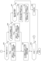
- 4 is a flowchart showing a processing operation of a processing unit of the control device according to the embodiment. 4 is a flowchart showing a processing operation of a processing unit of the control device according to the embodiment.
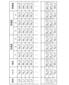
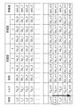
- 11 is an explanatory diagram showing an example of time-series data of detection information recorded in a storage unit of the control device according to the embodiment.
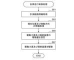
- 11 is an explanatory diagram showing success or failure of detection of guide information based on detection information of a distance measuring sensor according to the embodiment; 11 is a flowchart of a self-position estimation process performed by a self-position estimation unit of the control device according to the embodiment. 4 is a flowchart of an autonomous driving control process performed by an autonomous driving control unit of the control device according to the embodiment. 13 is an explanatory diagram showing an operation of moving the measuring device backward by an autonomous driving control unit of the control device according to the embodiment.
- FIG. 11 is an explanatory diagram showing an operation of restarting autonomous driving by an autonomous driving control unit of the control device according to the embodiment.
- FIG. 11 is an explanatory diagram showing an operation of restarting autonomous driving by an autonomous driving control unit of the control device according to the embodiment.
- FIG. 11 is a flowchart of a model generation process performed by a data processing unit of the information processing device according to the embodiment.
- the measuring device 10 captures an image of the road surface of the road R as the measurement target using an imaging device to generate road surface imaging data Img_ ⁇ , and transmits the generated road surface imaging data Img_ ⁇ to the information processing device 100 either sequentially or after imaging is completed.
- the information processing device 100 acquires the road surface imaging data Img_ ⁇ , and generates a road surface model, which is three-dimensional data showing the unevenness of the road surface, based on the acquired road surface imaging data Img_ ⁇ .
- the measuring device 10 divides the road R into three regions D1 to D3 and captures images of the road surface.
- the measuring device 10 generates time-series road surface image data Img_ ⁇ while autonomously traveling through each of the regions D1 to D3.
- Adjacent regions D1 to D3 are set to partially overlap each other so that the entire measurement range of the road R is not excluded from the imaging range.
- the measurement device 10 also has multiple imaging devices arranged along a direction (left-right direction) perpendicular to the direction of movement (forward-backward direction).
- the multiple imaging devices each capture images of the road surface while the measurement device 10 autonomously travels through each of the areas D1-D3, generating multiple road surface image data Img_ ⁇ .
- the multiple imaging devices are installed so that the imaging ranges P1-P6 of adjacent imaging devices partially overlap, so that the entirety of each of the areas D1-D3 is not excluded from the imaging range.
- the moving speed of the measuring device 10 is set so that the time-series road surface image data Img_ ⁇ generated by each imaging device partially overlaps.
- the imaging range at time t_n partially overlaps with the imaging range at the previous time t_n-1 and the imaging range at the next time t_n+1.
- the imaging range of a certain calculation cycle time t_n
- time t_n may overlap with the imaging range of the calculation cycle two cycles ago or earlier (times t_n-2, t_n-3, ...), and the imaging range of the calculation cycle two cycles after or later (times t_n+2, t_n+3, ).
- the information processing device 100 extracts feature points from the multiple road surface image data Img_ ⁇ that have been acquired, and executes feature point matching processing to align the feature points between the road surface image data Img_ ⁇ .
- the feature point matching processing is performed, for example, using SfM (Structure from Motion) processing.
- the information processing device 100 also synthesizes the multiple road surface image data Img_ ⁇ through the feature point matching processing, and generates a road surface model that indicates information on the unevenness of the road surface.
- the road surface model is generated, for example, using MVS (Multi-View Stereo) processing.
- FIGS. 2 and 3 are explanatory diagrams showing an example of the configuration of the measuring device 10.
- FIG. 2 is a side view of the measuring device 10
- FIG. 3 is a top view of the measuring device 10.
- the basic forward direction of the measuring device 10 is indicated as "front”
- the backward direction is indicated as "rear”.
- the front-rear direction, left-right direction, and height direction of the measuring device 10 refer to the front-rear direction, left-right direction, and height direction based on the "front” and "rear”.
- the measuring device 10 generates multiple road surface imaging data Img_ ⁇ by imaging the road surface as the measurement target, and transmits the generated road surface imaging data Img_ ⁇ to the information processing device 100.
- the measuring device 10 according to this embodiment is configured to be able to move on the road surface unmanned (capable of autonomous driving).
- the measuring device 10 includes a main body unit 3, an imaging unit 5, a surrounding condition detection unit 7, and a control device 50.
- the main body 3 includes a frame 11, wheels 13 (13F, 13R), a driving force source 15, and a steering device 17.
- the wheels 13 (13F, 13R), driving force source 15, and steering device 17 correspond to a driving device that moves the position of the measuring device 10.
- the frame 11 forms the skeleton of the main body 3.
- the structure and overall shape of the frame 11 shown in Figures 2 and 3 are merely examples, and the configuration of the frame 11 is not particularly limited.
- the wheels 13 include left and right front wheels 13F and rear wheels 13R.
- the driving force source 15 outputs a driving force to rotate the rear wheel 13R.
- a driving motor is a typical example of the driving force source 15, but there is no particular limitation as long as it is capable of outputting power to rotate the rear wheel 13R.
- the steering device 17 adjusts the steering angle of the front wheels 13F.
- An example of the steering device 17 is a steering device configured to rotate a pinion gear by a motor and move a rack left and right by the rotation of the pinion gear, but the configuration of the steering device 17 is not particularly limited.
- the main body 3 is not particularly limited in its specific configuration, so long as it can support the imaging unit 5 and the surrounding situation detection unit 7 and can travel while adjusting the direction of movement.
- the number of wheels 13 on the main body 3 does not need to be four, but may be three, or five or more.
- the wheels 13 that are driven to rotate by the power output from the driving force source 15 may be the front wheels 13F, or both the front wheels 13F and the rear wheels 13R may be driven to rotate.
- the driving force source 15 may be four driving motors that respectively drive the four wheels 13.
- the wheels whose steering angle is adjusted by the steering device 17 may be the rear wheels 13R, or all of the front wheels 13F and rear wheels 13R.
- the steering device can be omitted.
- the main body 3 also includes a wheel speed sensor 41.
- the wheel speed sensor 41 outputs a sensor signal corresponding to the rotation speed of the rear wheel 13R.
- the wheel speed sensor 41 may also output a sensor signal corresponding to the rotation speed of the front wheel 13F.
- the imaging unit 5 includes a plurality of imaging devices 21a-21f (hereinafter collectively referred to as imaging devices 21 unless otherwise required), irradiation lamps 25a-25f (hereinafter collectively referred to as irradiation lamps 25 unless otherwise required), and a reflector 23, and is provided at the rear of the main body 3.
- the imaging devices 21 are arranged along the left-right direction of the main body 3.
- Each imaging device 21 is installed with a uniform height and installation angle (direction of imaging).
- six imaging devices 21a to 21f are arranged at equal intervals along the left-right direction of the main body 3.
- Each imaging device 21 is installed with its imaging direction facing the road surface.
- the imaging devices 21 are installed so that the imaging ranges of adjacent imaging devices 21 overlap.
- the installation positions and installation angles of the multiple imaging devices 21 do not have to be uniform as long as the degree of overlap of the imaging ranges of adjacent imaging devices 21 can be maintained.
- the imaging directions of the imaging devices on both the left and right sides may be oriented toward the center.
- the number of imaging devices 21 is not limited to six. Furthermore, the imaging devices 21 do not have to be arranged at equal intervals. However, by arranging the imaging devices 21 at equal intervals, the relative positional relationship of the imaging data generated by adjacent imaging devices 21 becomes the same, making it easier to perform calculations.
- the irradiation lamps 25 are light sources for illuminating the road surface of the measurement target that is imaged by the imaging device 21.
- the light emitted from the irradiation lamps 25 is reflected by the reflector 23 to illuminate the road surface of the measurement target.
- the number of irradiation lamps 25 is not particularly limited as long as the brightness (illuminance or luminosity) of the road surface imaged by each imaging device 21 is uniform.
- the means for illuminating the road surface of the measurement target is not limited to the configuration example of this embodiment, and may have any configuration.
- the surrounding situation detection unit 7 has at least one sensor capable of detecting the surrounding situation of the measuring device 10.
- the surrounding situation detection unit 7 has distance measurement sensors 31a, 31b (hereinafter, collectively referred to as distance measurement sensor 31 unless a distinction is particularly required) and camera sensors 33a, 33b (hereinafter, collectively referred to as camera sensor 33 unless a distinction is particularly required).
- the distance measurement sensor 31 may be, for example, a LiDAR (Light Detection And Ranging), but may also be a radar sensor or an ultrasonic sensor.
- the camera sensor 33 has an imaging element such as a CCD or CMOS, and generates imaging data.
- the distance measuring sensors 31a and 31b are installed with the center of their measurement ranges facing the left and right front of the measurement device 10.
- the distance measuring sensors 31a and 31b are installed so that they can detect objects, such as targets, on the left and right sides of the measurement device 10.
- the camera sensors 33a and 33b are installed so that the center of their imaging ranges facing the front of the measurement device 10.
- the camera sensors 33a and 33b are installed so that they can capture a wide image of the area in front of the measurement device 10.
- the control device 50 includes one or more processors having a function for automatically moving the measuring device 10 and a function for controlling the imaging device 21, and one or more storage devices communicatively connected to the one or more processors.
- the control device 50 also includes a communication interface for communicating with the information processing device 100.
- the control device 50 is communicatively connected to various sensors and electronic control devices provided in the measuring device 10.
- FIG. 4 is a block diagram showing an example of the configuration of the measurement system 1.
- the control device 50 includes a processing unit 51, a storage unit 53, and a communication unit 57.
- the processing unit 51 includes one or more processors such as a CPU (Central Processing Unit) or a GPU (Graphics Processing Unit) and various peripheral components.
- a part or the whole of the processing unit 51 may be configured with updatable firmware or the like, or may be a program module or the like executed by a command from the CPU or the like.
- the processing unit 51 functions as a device that realizes the functions described below by one or more processors executing a computer program.
- the computer program is a computer program for causing the processor to execute the operations to be performed by the processing unit 51, which will be described later.
- the computer program executed by the processor may be recorded on a recording medium that functions as a storage unit (memory) 53 provided in the control device 50, or may be recorded on a recording medium built into the processing unit 51 or any recording medium that can be externally attached to the control device 50.
- Recording media for recording computer programs may include magnetic media such as hard disks, floppy disks, and magnetic tapes; optical recording media such as CD-ROMs, DVDs, and Blu-ray (registered trademark); magneto-optical media such as floptical disks; memory elements such as RAM and ROM; flash memories such as USB memory and SSDs; and other media capable of storing programs.
- the processing unit 51 is communicatively connected to the driving force source 15, steering device 17, imaging device 21, illumination lamp 25, distance measurement sensor 31, camera sensor 33, wheel speed sensor 41, input unit 81, and notification unit 83.
- the input unit 81 is a part that accepts input operations by a user.
- the input unit 81 is configured to include at least one of a keyboard, a mouse, a touchpad, and a microphone, for example.
- the type of the input unit 81 is not particularly limited.
- the notification unit 83 is a part that provides a predetermined notification to the user.
- the notification unit 83 is configured to include at least one of a display device and a speaker, for example.
- the type of the notification unit 83 is not particularly limited.
- the storage unit 53 is composed of one or more storage elements such as RAM or ROM that are communicatively connected to the processing unit 51. However, there is no particular limit to the type or number of the storage units 53.
- the storage unit 53 stores information such as computer programs executed by the processing unit 51, various parameters used in the calculation process, detection data, and calculation results. A part of the storage unit 53 is used as a work area.
- the communication unit 57 is an interface for the processing unit 51 to communicate with the information processing device 100.
- the communication unit 57 may be an interface for communicating with the information processing device 100 via mobile communication, for example, but the communication method with the information processing device 100 is not particularly limited.
- the control device 50 also includes an acceleration sensor 43, an angular velocity sensor 45, a GNSS (Global Navigation Satellite System) sensor 47, and a map data storage unit 55, all of which are communicatively connected to the processing unit 51. Note that some or all of the acceleration sensor 43, the angular velocity sensor 45, the GNSS (Global Navigation Satellite System) sensor 47, and the map data storage unit 55 may be provided separately from the control device 50.
- the acceleration sensor 43 and the angular velocity sensor 45 function as inertial measurement sensors.
- the acceleration sensor 43 outputs a sensor signal corresponding to the acceleration in each of the three axial directions along the front-rear, left-right, and height directions of the measuring device 10.
- the angular velocity sensor 45 outputs a sensor signal corresponding to the angular velocity around each of the three axes along the front-rear, left-right, and height directions of the measuring device 10.
- the acceleration sensor 43 and the angular velocity sensor 45 may be sensors integrated as an IMU sensor (inertial measurement unit) or may be sensors provided separately.
- the GNSS sensor 47 receives satellite signals from positioning satellites such as GPS (Global Positioning System) satellites, and transmits position information of the measuring device 10 contained in the satellite signals to the processing unit 51.
- the position information may be latitude and longitude information.
- the GNSS sensor 47 may be configured to receive satellite signals from satellite systems other than GPS satellites.
- the map data storage unit 55 is composed of a storage element such as a RAM or ROM connected to the processing unit 51 so as to be able to communicate with it, or a storage medium such as a HDD, CD, DVD, SSD, USB flash, or storage device.
- the map data stored in the map data storage unit 55 is associated with latitude and longitude information, and the processing unit 51 can identify the position of the measuring device 10 on the map data based on the latitude and longitude information of the measuring device 10 transmitted from the GNSS sensor 35.
- the processing unit 51 executes a process of starting to capture an image of the road surface using the imaging device 21 and transmitting the captured image data to the information processing device 100 .
- the processing unit 51 includes an acquisition unit 61, an imaging condition setting unit 63, an autonomous driving control unit 67, a self-position estimation unit 65, and an imaging device driving unit 69.
- Each of these units is a function realized by the execution of a computer program by one or more processors.
- the acquisition unit 61, the imaging condition setting unit 63, the autonomous driving control unit 67, the self-position estimation unit 65, and the imaging device driving unit 69 may be configured using analog circuits.
- the acquisition unit 61 acquires road surface image data generated by the imaging device 21.
- the acquisition unit 61 acquires road surface image data generated by the imaging device 21 at set time intervals.
- the acquisition unit 61 also , the distance measurement sensor 31, the camera sensor 33, the wheel speed sensor 41, the acceleration sensor 43, the angular velocity sensor 45, and the GNSS sensor 47, respectively, and obtain detection data or sensor signals (hereinafter, collectively referred to as "detection information") outputted from the sensor.
- detection information detection data or sensor signals
- the imaging condition setting unit 63 sets imaging conditions as operating conditions of the imaging device 21. Specifically, the imaging condition setting unit 63 sets the moving speed of the imaging device 21, i.e., the moving speed of the measurement device 10. The imaging condition setting unit 63 sets a moving speed at which the imaging ranges of the road surface imaging data acquired in time series partially overlap, based on the length of the road surface corresponding to the pixel size of the road surface imaging data captured by each imaging device 21 and the time interval of imaging by the imaging device 21. The imaging condition setting unit 63 also sets the aperture (F value), shutter speed, and ISO sensitivity of the imaging device 21.
- the information for setting the imaging conditions may be specified by the user.
- the user may manually set some or all of the acquired imaging conditions.
- the imaging condition setting unit 63 may also set the output (illuminance or brightness) of the irradiation lamp 25. Note that the imaging condition setting unit 63 does not need to perform setting processing for conditions that are fixed regardless of other conditions.
- the self-position estimation unit 65 estimates the position of the measurement device 10 on a predetermined three-dimensional coordinate system (hereinafter, also referred to as the “self-position”). When the position information cannot be acquired, the self-position of the measurement device 10 is estimated by a predetermined calculation.
- the self-position of the measurement device 10 is, for example, the measurement device position on a predetermined three-dimensional coordinate system with the start position of the measurement process as the origin.
- the self-location of the measurement device 10 may be the location of a reference point (x 0 , y 0 , z 0 ) arbitrarily set within the measurement device 10, for example, the center of gravity of the measurement device 10. It may be a position of the imaging device 21, or it may be a position of any one of the multiple imaging devices 21a to 21f.
- the self-position estimation unit 65 estimates the self-position of the measurement device 10 based on the guide information and the detection information from the wheel speed sensor 41, the acceleration sensor 43, and the angular velocity sensor 45.
- the distance sensor 31 corresponds to the surrounding environment sensor described in the claims.
- Guide information refers to a three-dimensional object that does not have speed, such as a side wall, a curb, or a guardrail, that is installed along a road with a certain level of continuity, and can serve as a reference when moving the measurement device 10.
- the self-position estimation unit 65 if the self-position estimation unit 65 cannot detect guide information based on the measurement data of the distance measurement sensor 31, but can detect guide information based on image data generated by the camera sensor 33, it estimates the self-position of the measurement device 10 based on the guide information and the detection information of the wheel speed sensor 41, the acceleration sensor 43, and the angular velocity sensor 45.
- the camera sensor 33 corresponds to the other sensor described in the claims.
- the self-position estimation unit 65 estimates the self-position of the measurement device 10 based on the detection information of the wheel speed sensor 41, the acceleration sensor 43, and the angular velocity sensor 45.
- the present invention is configured on the premise that the object detection accuracy and the measurement accuracy of the distance to the object measured by the distance sensor 31 are higher than the measurement accuracy of the object and the distance to the object measured by the camera sensor 33.
- the self-position estimation unit 65 estimates the self-position of the measurement device 10 by using the distance sensor 31 preferentially over the camera sensor 33. Furthermore, if the camera sensor 33 cannot detect guide information, the self-position of the measurement device 10 is estimated based only on the detection information of the wheel speed sensor 41, the acceleration sensor 43, and the angular velocity sensor 45.
- the priority of the sensors used by the self-position estimation unit 65 may be set arbitrarily according to the measurement accuracy of each sensor.
- the autonomous driving control unit 67 controls the autonomous driving of the measuring device 10.
- Autonomous driving refers to a driving state in which a processor or the like controls the driving of the driving force source 15 and the steering device 17 based on detection information, so that the measuring device 10 moves along a predetermined target route.
- the autonomous driving control unit 67 basically moves the measuring device 10 along the measurement route based on the position information of the measuring device 10 detected by the GNSS sensor 47 and the information of the measurement route set on the map data. As long as the GNSS sensor 47 is in an area where it can receive satellite signals, the autonomous driving control unit 67 can move the measuring device 10 along the previously set measurement route using the position information detected by the GNSS sensor 47.
- the autonomous driving control unit 67 moves the measuring device 10 using information on the self-position of the measuring device 10 estimated by the self-position estimation unit 65. For example, the autonomous driving control unit 67 executes a process of moving the measuring device 10 along the measurement route while maintaining the distance between such guide information and the measuring device 10 at a predetermined set distance.
- the imaging device driving unit 69 controls driving of the imaging device 21.
- the imaging device driving unit 69 controls imaging by the imaging device 21 in accordance with the imaging conditions (aperture (F value), shutter speed, and ISO sensitivity) set by the imaging condition setting unit 63.
- FIGS. 5 and 6 show flowcharts of the processing operation of the processing unit 51.
- the flowchart described below is executed when the position information of the GNSS sensor 47 cannot be acquired, for example, when the GNSS sensor 47 cannot receive satellite signals.
- the processing unit 51 can acquire position information from the GNSS sensor 47, a detailed description is omitted because publicly known technology can be used to acquire road surface image data using the imaging device 21 while moving the measuring device 10 along the measurement route based on the position information of the GNSS sensor 47.
- the imaging device driving unit 69 acquires the imaging conditions (aperture (F-number), shutter speed, and ISO sensitivity) set by the imaging condition setting unit 63 (step S11).
- the autonomous driving control unit 67 acquires information on the measurement route (step S13).
- the measurement route includes information on at least the measurement start position and the measurement end position.
- the measurement route information may be set in advance by the user, or may be set by the autonomous driving control unit 67 based on a specified measurement range.
- the self-position estimation unit 65 records a starting position that is a reference for calculating the self-position of the measurement device 10 (step S15).
- the self-position estimation unit 65 records the position coordinates of the reference position ( x0 , y0 , z0 ) of the measurement device 10 at the start of the measurement process as the starting position.
- the recorded reference position does not need to be specified by specific latitude and longitude information, and may be recorded as an arbitrary point of arbitrary three-dimensional coordinates (for example, the origin of a three-dimensional coordinate system).
- the self-position estimation unit 65 also records a first distance between the measuring device 10 and the guide information when the measuring device 10 is located at the start position.
- the first distance between the measuring device 10 and the guide information may be a distance value measured by the distance measurement sensor 31, or may be a value obtained by converting the distance value measured by the distance measurement sensor 31 into a distance value from a reference position set in the measuring device 10 to the guide information.
- the imaging device driving unit 69 controls the driving of the imaging device 21 (step S17).
- the imaging device driving unit 69 controls the driving of the imaging device 21 under the set imaging conditions, and executes a process of imaging the road surface to be measured.
- the self-position estimation unit 65 acquires detection information output from the distance measurement sensor 31, camera sensor 33, wheel speed sensor 41, acceleration sensor 43, and angular velocity sensor 45 (step S21).
- the sensor signal of the distance measurement sensor 31 includes information on the direction in which a reflection point (measurement point) caused by an object existing within the detection range is located and the distance to the reflection point.
- the detection information of the acceleration sensor 43 includes information indicating the acceleration in three axial directions along the front-rear, left-right, and height directions of the measurement device 10.
- the detection information of the angular velocity sensor 45 includes information indicating the angular velocity around three axes along the front-rear, left-right, and height directions of the measurement device 10.
- the acquired detection information is recorded in the memory unit 53 as time-series data.
- FIG. 7 is an explanatory diagram showing an example of time-series data of the detection information recorded in the storage unit 53.
- the detection information acquired at each time t_n includes information on the torque (Tq_n) of the driving force source 15, the steering angle (SA_n) of the wheels 13, the acceleration in each of the three axial directions (Ax_n, Ay_n, Az_n), the angular velocity around each of the three axes (Gx_n, Gy_n, Gz_n), and the wheel speed (rpm_n).
- the information on the torque (Tq_n) of the driving force source 15 and the steering angle (SA_n) of the wheels 13 may be command values for the driving force source 15 and the steering device 17, or may be detection information from a sensor that detects the torque (Tq_n) of the driving force source 15 or the steering angle (SA_n) of the wheels 13.
- the self-position estimation unit 65 searches for guide information based on the acquired detection information from the distance measurement sensor 31 (step S23). Specifically, the self-position estimation unit 65 determines whether or not a detection target corresponding to guide information is included in the measurement point data output from the distance measurement sensor 31. For example, the self-position estimation unit 65 determines whether or not a detection target with a speed of at least zero along the movement direction of the measurement device 10 is included in the direction in which the guide information is assumed to exist, at a distance of the first distance recorded in step S13.
- FIG. 8 is an explanatory diagram showing an example in which guide information is detected and an example in which guide information is not detected based on the detection information of the distance measurement sensor 31.
- the example shown in Fig. 8 shows an example of a case where a road R inside a tunnel is photographed.
- the measuring device 10 detects side walls W1 and W2 on both the left and right sides.
- the measuring device 10 detects that one W1' or both W1' and W2' of the side walls on both the left and right sides are discontinued midway.
- An example where guide information is not detected may be a detection error of the side wall, or it may be a case where a side wall does not actually exist.
- the self-position estimation unit 65 determines whether or not the guide information has been detected based on the acquired detection information of the distance measurement sensor 31 (step S25). If the self-position estimation unit 65 determines that the guide information has been found (S25/Yes), it estimates the self-position of the measurement device 10 using the detection information of the distance measurement sensor 31, the acceleration sensor 43, and the angular velocity sensor 45 (step S27).
- the self-position estimation unit 65 estimates the self-position of the measurement device 10 on a predetermined three-dimensional coordinate system based on the distance from the measurement device 10 to the guide information obtained from the detection information of the distance measurement sensor 31, and the change in the movement distance and movement direction from the previous calculation cycle, which are obtained based on the detection information of the acceleration sensor 43 and the angular velocity sensor 45.
- FIG. 9 is a flowchart showing the self-location estimation process performed by the self-location estimation unit 65.
- the self-position estimation unit 65 acquires the distance from the measuring device 10 to the guide information based on the detection information of the distance measuring sensor 31 (step S51).
- the self-position estimation unit 65 acquires the acceleration and angular velocity information obtained from the detection information of the acceleration sensor 43 and the angular velocity sensor 45 acquired in the current calculation cycle (step S53).
- the self-position estimation unit 65 calculates odometry information including the self-position of the measuring device 10 based on information on the distance from the measuring device 10 to the guide information, information on the acceleration and angular velocity of the measuring device 10, and information on the position of the measuring device 10 calculated in the previous calculation cycle (step S55). For example, the self-position estimation unit 65 calculates the position of the measuring device 10 on a three-dimensional coordinate system with the start position recorded in step S15 as the origin.
- the self-position estimation unit 65 records the data of the position of the measuring device 10 (position coordinates of the self-position) P_n (x_n, y_n) calculated in the current calculation cycle (t_n) in the memory unit 53 (step S57).
- the self-position estimation unit 65 determines whether or not it is possible to recognize the situation around the measurement device 10 based on the image data output from the camera sensor 33 (step S29). Specifically, the self-position estimation unit 65 determines whether or not it is possible to recognize white lines, yellow lines, boundary lines, guardrails, etc., which may serve as landmarks when moving the measurement device 10 along the measurement path, based on the image data output from the camera sensor 33. Whether or not these white lines, etc., can be recognized can be determined using a known image matching process.
- the self-position estimation unit 65 determines that the surrounding situation of the measuring device 10 can be recognized based on the image data output from the camera sensor 33 (S29/Yes), it estimates the self-position of the measuring device 10 using the image data of the camera sensor 33 and the detection information of the acceleration sensor 43 and the angular velocity sensor 45 (step S31). Specifically, the self-position estimation unit 65 switches the information for guiding the measuring device 10 along the measurement path from the guide information to alternative guide information such as a white line detected by the camera sensor 33, and further estimates the self-position of the measuring device 10 on a predetermined three-dimensional coordinate system based on the change in the moving distance and moving direction from the previous calculation cycle, which is obtained based on the detection information of the acceleration sensor 43 and the angular velocity sensor 45.
- the self-position estimation process is performed by replacing the distance to the guide information acquired in step S51 of the self-position estimation process shown in FIG. 8 with the distance to the alternative guide information.
- the autonomous driving control unit 67 causes the measuring device 10 to autonomously drive based on the guide information or alternative guide information and the measurement route information (step S33).
- FIG. 10 is a flowchart showing the autonomous driving control process of the measuring device 10 performed by the autonomous driving control unit 67.
- the autonomous driving control unit 67 acquires information on the measurement route (step S61).
- the autonomous driving control unit 67 acquires information on the current position (x, y) and moving direction of the measurement device 10 (step S63).
- the autonomous driving control unit 67 acquires information on the current position (x, y) and moving direction of the measurement device 10 on a predetermined two-dimensional coordinate system based on information on the distance from the measurement device 10 to the guide information and the odometry information estimated by the self-position estimation unit 65.
- the autonomous driving control unit 67 sets the drive amount of the driving force source 15 and the steering device 17 (step S65). For example, the autonomous driving control unit 67 sets the drive amount of the driving force source 15 so that the moving speed of the measuring device 10 calculated based on the detection information of the wheel speed sensor 41 becomes the moving speed set by the imaging condition setting unit 63. In addition, the autonomous driving control unit 67 sets the angular velocity of the change in the steering angle (steering angular velocity) based on information on the current moving direction of the measuring device 10, information on the distance from the measuring device 10 to the guide information, and information on the measurement route, and sets the drive amount of the steering device 17 according to the steering angular velocity.
- the autonomous driving control unit 67 sets the drive amount of the driving force source 15 so that the moving speed of the measuring device 10 calculated based on the detection information of the wheel speed sensor 41 becomes the moving speed set by the imaging condition setting unit 63.
- the autonomous driving control unit 67 sets the angular velocity of the change in the steering angle (steering ang
- the autonomous driving control unit 67 controls the driving of the driving force source 15 and the steering device 17 according to the driving amount set in step S65 (step S67).
- step S29 if the self-position estimation unit 65 does not determine that the situation around the measuring device 10 can be recognized based on the image data output from the camera sensor 33 (S29/No), the autonomous driving control unit 67 determines whether or not time-series data of the detection information prior to the current time has been stored (step S37). In other words, the autonomous driving control unit 67 determines whether or not the time-series data of the detection information shown in FIG. 7 has been stored in the memory unit 53.
- the processing unit 51 stops the processing operation (step S43) because there is no information for returning the measuring device 10 to any of the positions where the estimated result of the measuring device 10's position is recorded, or there is no estimated result of the measuring device 10's position. In other words, the processing unit 51 forcibly ends the measurement of the road surface.
- the autonomous driving control unit 67 determines that time series data of detection information before the current time has been stored (S37/Yes), it causes the measuring device 10 to move backwards to a predetermined position where guide information is detected and the self-position estimation result is recorded based on the stored detection information (step S39).
- the autonomous driving control unit 67 causes the measuring device 10 to move autonomously based on the detection information of the acceleration sensor 43 and the angular velocity sensor 45 (step S41). In other words, the autonomous driving control unit 67 causes the measuring device 10 to move along the measurement route using the acceleration and angular velocity information of the measuring device 10 without using guide information.
- FIG. 11 and 12 are explanatory diagrams showing an example in which the measuring device 10 resumes autonomous traveling without using guide information after the measuring device 10 is moved backward.
- the autonomous driving control unit 67 At time t_n in Fig. 11, it is assumed that the autonomous driving control unit 67 is no longer able to detect the guide information (side wall W1').
- the autonomous driving control unit 67 reads out the detection information data for the previous or previous calculation cycle (t_n-1, t_n-2, ...) from the time series data of the detection information shown in Fig. 7.
- the autonomous driving control unit 67 controls the torque of the driving force source 15 and the steering angle of the wheels 13 so as to go back to the previous or previous calculation cycle, and causes the measurement device 10 to move backward to a predetermined position where the estimation result of the self-position of the measurement device 10 is recorded (white arrow in Fig. 13).
- the steering angle of the wheels 13 is adjusted to the stored value going back to the calculation cycle before the previous one.
- the drive amount of the driving force source 15 is adjusted to a negative value of the stored value going back to the calculation cycle before the previous one.
- the autonomous driving control unit 67 can cause the measuring device 10 to move backward along the trajectory it has traveled. In FIG. 11, the measuring device 10 has moved backward to the position of the measuring device 10 at time t_n-2.
- the autonomous driving control unit 67 reverses the measuring device 10 to a predetermined position, and then causes the measuring device 10 to autonomously drive along the measurement path based on the detection information from the acceleration sensor 43 and the angular velocity sensor 45 (black arrow in FIG. 13).
- the autonomous driving control unit 67 determines the direction of acceleration and the direction of angular velocity of the measuring device 10 at each time t from the detection information from the acceleration sensor 43 and the angular velocity sensor 45, and sets a steering angle SA for moving the measuring device 10 along the measurement path.
- the autonomous driving control unit 67 may also reduce the torque of the driving force source 15, i.e., the moving speed of the measuring device 10, compared to when the measuring device 10 is autonomously driven based on guide information. This makes it possible to prevent significant deviation from the measurement route when the measuring device 10 is autonomously driven based only on detection information from the acceleration sensor 43 and angular velocity sensor 45 without using guide information.
- the autonomous driving control unit 67 determines whether or not the measurement has ended (step S35). For example, the autonomous driving control unit 67 determines that the measurement has ended when the measuring device 10 reaches the measurement end position. Alternatively, the autonomous driving control unit 67 may determine that the measurement has ended when an emergency stop operation is performed by a user or the like.
- the processing unit 51 If the autonomous driving control unit 67 does not determine that the measurement has ended (S35/No), the processing unit 51 returns to step S17 and continues the processing of each step described up to this point. On the other hand, if the autonomous driving control unit 67 determines that the measurement has ended (S35/Yes), the processing unit 51 ends the processing operation.
- the data processing unit 103 is configured with one or more processors, such as a CPU (Central Processing Unit) or a GPU (Graphics Processing Unit), and various peripheral components.
- processors such as a CPU (Central Processing Unit) or a GPU (Graphics Processing Unit), and various peripheral components.
- a part or all of the processing unit 51 may be configured with updatable components, such as firmware, or may be a program module executed by commands from a CPU, etc.
- the data processing unit 103 functions as a device that realizes the functions described below by one or more processors executing a computer program.
- the computer program is a computer program for causing the processor to execute the operations to be performed by the data processing unit 103, which will be described later.
- the computer program executed by the processor may be recorded on a recording medium that functions as a storage unit (memory) 105 provided in the information processing device 100, or may be recorded on a recording medium built into the data processing unit 103 or any recording medium that can be attached externally to the information processing device 100.
- Recording media for recording computer programs may include magnetic media such as hard disks, floppy disks, and magnetic tapes; optical recording media such as CD-ROMs, DVDs, and Blu-ray (registered trademark); magneto-optical media such as floptical disks; memory elements such as RAM and ROM; flash memories such as USB memory and SSDs; and other media capable of storing programs.
- the storage unit 105 is composed of one or more storage elements such as RAM or ROM, or storage media such as HDD or SSD, communicably connected to the data processing unit 103. However, there is no particular limit to the type or number of the storage units 105.
- the storage unit 105 stores information such as computer programs executed by the data processing unit 103, various parameters used in arithmetic processing, detection data, and calculation results. A part of the storage unit 105 is used as a work area.
- a feature point may be a point where the amount of change in luminance (feature value) between adjacent pixels in the road surface imaging data Img_ ⁇ _n is equal to or greater than a predetermined threshold value, but other feature values may also be used.
- the method for extracting feature points from imaging data may be a conventionally known method, so a detailed description will be omitted.
- the process of matching feature points between imaging data may be executed by a conventionally known method, and therefore a detailed description thereof will be omitted.
- the data processing unit 103 constructs three-dimensional point cloud data by MVS (Multi-View Stereo) processing, and generates a road surface model.
- MVS Multi-View Stereo
- the method of generating a road surface model composed of three-dimensional point cloud data is not particularly limited.
- the data processing unit 103 determines whether or not to end the model generation process (step S79). For example, the data processing unit 103 may determine to end the model generation process when a predetermined time has elapsed since the control device 50 stopped transmitting road surface imaging data Img_ ⁇ . Alternatively, the data processing unit 103 may determine to end the model generation process when the control device 50 transmits a signal indicating the end of measurement.
- the data processing unit 103 If the data processing unit 103 does not determine that the model generation process should be terminated (S79/No), the data processing unit 103 returns to step S71 and continues the model generation process. On the other hand, if the data processing unit 103 determines that the model generation process should be terminated (S79/Yes), the data processing unit 103 terminates the model generation process.
- the measurement system 1 can capture images of the road surface while autonomously driving the measurement device 10 equipped with an imaging device along a measurement route based on guide information to obtain road surface imaging data for generating a road surface model.
- the measurement system 1 also has a self-position estimation function for the measurement device 10, and can continue autonomous driving of the measurement device 10 based on detection information from the inertial measurement sensor after backing up the measurement device 10 to a predetermined position where the estimated result of the self-position is recorded when guide information is no longer detected. Therefore, even if guide information is no longer detected while road surface imaging data is being automatically collected using the relative positional relationship between the guide information and the measurement device 10, imaging can be continued.
- the measurement system 1 when guide information is no longer detected, the measurement system 1 causes the measurement device 10 to retreat to a predetermined position based on the stored record of the driving amount of the measurement device 10. Therefore, the measurement device 10 can be retreated to a predetermined position along the trajectory along which the measurement device 10 has moved, and deviation in the position of the measurement device 10 can be suppressed when autonomous driving is subsequently resumed.
- the measurement device 10 when guide information is no longer detected by the distance measurement sensor 31 such as LiDAR, and the surrounding situation can be recognized by the camera sensor 33, the measurement device 10 is caused to travel autonomously along the measurement route based on alternative guide information. Therefore, before causing the measurement device 10 to travel autonomously using only the detection information of the inertial measurement sensor, it is possible to attempt autonomous travel of the measurement device 10 that also utilizes the recognition results of the camera sensor 33, and the accuracy of the autonomous travel of the measurement device 10 along the measurement route can be maintained relatively high.
- the measurement system 1 reduces the moving speed of the measurement device 10 when the measurement device 10 is made to travel autonomously using the detection information of the inertial measurement sensor, compared to when the detection information of the distance measuring sensor 31 is used. Therefore, it is possible to suppress deviation from the measurement route when the measurement device 10 is made to travel autonomously using only the detection information of the inertial measurement sensor.
- the moving speed, F-number, shutter speed, and ISO sensitivity of the imaging device are set as the imaging conditions, but the imaging conditions are not limited to the above examples.
- the imaging conditions may also include the output (illuminance or brightness) of the irradiating lamp. This can further improve the matching accuracy of feature points.
- the measurement system of the above embodiment is configured as a measurement system that generates a three-dimensional model of the unevenness of the road surface as the measurement target, but the measurement target is not limited to the road surface and may be any measurement target.
- the measurement device used in the measurement system of the above embodiment is configured as a measurement device that can travel on the road surface, but the measurement device may be configured as an unmanned or manned flying object. In this case, the measurement device identifies its own position and orientation in three-dimensional space, making it possible to calculate the imaging range of each imaging data, the distance from the imaging device to the measurement target, etc., and the technology disclosed herein can be applied.
- the measurement system of the above embodiment is configured by a measurement device that mainly acquires imaging data and an information processing device that mainly executes data processing, which are connected so as to be able to communicate with each other, but the technology of the present disclosure is not limited to the above example.
- Some of the functions of the data processing unit of the information processing device may be provided in the measurement device.
- the information processing device may be mounted in the measurement device, or all of the functions of the data processing unit of the information processing device may be provided in the control device of the measurement device, and the measurement system may be configured only by the measurement device.
- the technology disclosed herein can also be realized as a measuring device equipped with the control device described in the above embodiment, a method for controlling the measuring device by the control device, an information processing method executed by the above information processing device, a computer program that causes a computer to function as at least one of the above control device and information processing device, and a non-transitory tangible recording medium on which the computer program is recorded.
- Measurement system 10 Measurement device 13: Wheel 15: Driving force source 17: Steering device 21: Imaging device 23: Reflector 25: Irradiation lamp 31: Distance measurement sensor 33: Camera sensor 35: GNSS sensor 41: Wheel speed sensor 43: Acceleration sensor 45: Angular velocity sensor 47: GNSS sensor 50: Control device 51: Processing unit 53: Memory unit 55: Map data memory unit 57: Communication unit 61: Acquisition unit 63: Imaging condition setting unit 65: Self-position estimation unit 67: Autonomous driving control unit 69: Imaging device driving unit 81: Input unit 83: Notification unit 100: Information processing device 101: Communication unit 103: Data processing unit 105: Memory unit R: Road W1: Side wall W2: Side wall
Landscapes
- Control Of Position, Course, Altitude, Or Attitude Of Moving Bodies (AREA)
Abstract
計測装置を自律走行させながら撮像装置により計測対象を撮影する制御装置は、周囲環境センサにより検出されるガイド情報に基づいて計測装置を計測経路に沿って自律走行させ、慣性計測センサの検出情報に基づいて計測装置の位置を推定し、周囲環境センサによりガイド情報が検出されなくなった場合、周囲環境センサによりガイド情報が検出され、かつ、計測装置の位置の推定結果が記録されている所定の位置まで計測装置を後退させた後、慣性計測センサの検出情報に基づいて計測装置を計測経路に沿って自律走行させる。
Description
本開示は、計測システム、計測装置、計測装置の制御方法及び記録媒体に関する。
相互に重なり合う重複領域を有する複数の撮像データを合成して合成データを生成する技術が種々用いられている。例えば特許文献1には、複数のステレオ撮像手段により移動体の走行面を撮像した奥行方向の距離情報を含む複数の撮像画像を取得し、各ステレオ撮像画像から抽出される特徴点をマッチングして、取得した複数の撮像画像を重複させて走行面の幅員方向に繋ぐ制御装置が開示されている。
ここで、撮像データを収集するための装置(計測装置)を自律走行可能にすることにより、合成データを生成するために用いる撮像データを自動で収集することが可能になる。計測装置を自律走行可能にするには、計測装置を計測経路に沿って移動させることが必要になる。例えばGPS(Global Positioning System)等の衛星システムを活用することで、計測装置を計測経路に沿って自律走行させることができる。しかしながら、例えばトンネル内などの衛星信号を受信できない環境下においては計測装置を自律走行させることができない。
一方、衛星システムを活用する代わりに、計測対象の環境内に存在する側壁などの、センサにより検出可能な固定物との相対位置関係を活用して計測装置を自律走行させることも考えられる。しかしながら、計測装置を自律走行させている間に、そのような側壁等が途切れてしまった場合には、計測装置が計測経路から外れてしまったり、自律走行が不可能になったりするおそれがある。
本開示は、上記問題に鑑みてなされたものであり、本開示の目的とするところは、計測環境内にある固定物との相対位置関係を活用して計測装置を自律走行させている間に、当該固定物が検出されなくなった場合であっても、計測装置の自律走行を継続可能な計測システム、計測装置、計測装置の制御方法及び記録媒体を提供することにある。
上記課題を解決するために、本開示のある観点によれば、計測対象を撮影した複数の撮像データを合成し、上記計測対象のモデルのデータを生成する計測システムにおいて、上記計測対象を撮影し上記撮像データを生成する撮像装置と、上記撮像装置を搭載した計測装置と、上記計測装置の周囲環境を検出する周囲環境センサと、上記計測装置の加速度及び角速度を検出する慣性計測センサと、上記計測装置を自律走行させながら上記撮像装置により上記計測対象を撮影する制御装置と、上記撮像装置により撮像された上記複数の撮像データを取得し、取得した上記複数の撮像データを合成して上記計測対象のモデルのデータを生成する情報処理装置と、を備え、上記制御装置は、上記計測装置を移動させる計測経路の情報を取得し、上記周囲環境センサにより検出されるガイド情報に基づいて上記計測装置を上記計測経路に沿って自律走行させる自律走行制御処理と、上記慣性計測センサの検出情報に基づいて上記計測装置の位置を推定する自己位置推定処理と、を実行し、上記自律走行制御処理において上記周囲環境センサにより上記ガイド情報が検出されなくなった場合、上記周囲環境センサにより上記ガイド情報が検出され、かつ、上記計測装置の位置の推定結果が記録されている所定の位置まで上記計測装置を後退させた後、上記慣性計測センサの検出情報に基づいて上記計測装置を上記計測経路に沿って自律走行させる計測システムが提供される。
また、上記課題を解決するために本開示の別の観点によれば、計測対象を撮影した複数の撮像データを合成し、上記計測対象のモデルのデータを生成するための上記撮像データを収集する計測装置において、上記計測対象を撮影し上記撮像データを生成する撮像装置と、上記撮像装置を搭載した計測装置と、上記計測装置の周囲環境を検出する周囲環境センサと、上記計測装置の加速度及び角速度を検出する慣性計測センサと、上記計測装置を自律走行させながら上記撮像装置により上記計測対象を撮影する制御装置と、を備え、上記制御装置は、上記計測装置を移動させる計測経路の情報を取得し、上記周囲環境センサにより検出されるガイド情報に基づいて上記計測装置を上記計測経路に沿って自律走行させる自律走行制御処理と、上記慣性計測センサの検出情報に基づいて上記計測装置の位置を推定する自己位置推定処理と、を実行し、上記自律走行制御処理において上記周囲環境センサにより上記ガイド情報が検出されなくなった場合、上記周囲環境センサにより上記ガイド情報が検出され、かつ、上記計測装置の位置の推定結果が記録されている所定の位置まで上記計測装置を後退させた後、上記慣性計測センサの検出情報に基づいて上記計測装置を上記計測経路に沿って自律走行させる計測装置が提供される。
また、上記課題を解決するために本開示の別の観点によれば、計測対象を撮影した複数の撮像データを合成し、上記計測対象のモデルのデータを生成するための上記撮像データを収集する計測装置の制御方法において、上記計測装置は、上記計測対象を撮影し上記撮像データを生成する撮像装置と、上記計測装置の周囲環境を検出する周囲環境センサと、上記計測装置の加速度及び角速度を検出する慣性計測センサと、上記計測装置を自律走行させながら上記撮像装置により上記計測対象を撮影する制御装置と、を備え、上記制御装置は、上記計測装置を移動させる計測経路の情報を取得し、上記周囲環境センサにより検出されるガイド情報に基づいて上記計測装置を上記計測経路に沿って自律走行させる自律走行制御処理と、上記慣性計測センサの検出情報に基づいて上記計測装置の位置を推定する自己位置推定処理と、を実行し、上記自律走行制御処理において上記周囲環境センサにより上記ガイド情報が検出されなくなった場合、上記周囲環境センサにより上記ガイド情報が検出され、かつ、上記計測装置の位置の推定結果が記録されている所定の位置まで上記計測装置を後退させた後、上記慣性計測センサの検出情報に基づいて上記計測装置を上記計測経路に沿って自律走行させる計測装置の制御方法が提供される。
また、上記課題を解決するために本開示の別の観点によれば、計測対象を撮影した複数の撮像データを合成し、上記計測対象のモデルのデータを生成するための上記撮像データを収集する計測装置を制御するプログラムであって、上記計測装置は、上記計測対象を撮影し上記撮像データを生成する撮像装置と、上記撮像装置を搭載した計測装置と、上記計測装置の周囲環境を検出する周囲環境センサと、上記計測装置の加速度及び角速度を検出する慣性計測センサと、上記計測装置を自律走行させながら上記撮像装置により上記計測対象を撮影する制御装置と、を備え、コンピュータに、上記計測装置を移動させる計測経路の情報を取得し、上記周囲環境センサにより検出されるガイド情報に基づいて上記計測装置を上記計測経路に沿って自律走行させることと、上記慣性計測センサの検出情報に基づいて上記計測装置の位置を推定することと、上記自律走行させる間に上記周囲環境センサにより上記ガイド情報が検出されなくなった場合、上記周囲環境センサにより上記ガイド情報が検出され、かつ、上記計測装置の位置の推定結果が記録されている所定の位置まで上記計測装置を後退させた後、上記慣性計測センサの検出情報に基づいて上記計測装置を上記計測経路に沿って自律走行させることと、を実行させるプログラムを記録した、非一時的な有形の記録媒体が提供される。
以上説明したように本開示によれば、計測環境内にある固定物との相対位置関係を活用して計測装置を自律走行させている間に、当該固定物が検出されなくなった場合であっても、計測装置の自律走行を継続することができる。
以下、添付図面を参照しながら、本開示の好適な実施の形態について詳細に説明する。なお、本明細書及び図面において、実質的に同一の構成を有する構成要素については、同一の符号を付することにより重複説明を省略する。
<<1.計測システムの概要>>
はじめに、本開示の実施形態に係る計測システムの概要を説明する。
はじめに、本開示の実施形態に係る計測システムの概要を説明する。
図1は、本開示の計測システムの用途の一例を説明するために示す図である。
図1に示した例において、計測システム1は、撮像装置を搭載した計測装置10と、計測装置10と通信可能に接続された情報処理装置100とを備えている。計測装置10と情報処理装置100とは、例えばクラウドコンピューティングの技術を用いて通信可能に接続される。
図1に示した例において、計測システム1は、撮像装置を搭載した計測装置10と、計測装置10と通信可能に接続された情報処理装置100とを備えている。計測装置10と情報処理装置100とは、例えばクラウドコンピューティングの技術を用いて通信可能に接続される。
計測装置10は、計測対象としての道路Rの路面を撮像装置により撮像して路面撮像データImg_αを生成し、生成した路面撮像データImg_αを、逐次又は撮像終了後に、情報処理装置100へ送信する。情報処理装置100は、路面撮像データImg_αを取得し、取得した路面撮像データImg_αに基づいて、路面の凹凸状態を示す三次元データである路面モデルを生成する。
例えば計測装置10は、道路Rを三つの領域D1~D3に分けて路面の撮像を行う。計測装置10は、それぞれの領域D1~D3を自律走行しながら時系列の路面撮像データImg_αを生成する。道路Rの計測範囲の全体が撮像範囲から漏れることのないように、隣り合う領域D1~D3同士が一部重複するように設定されている。
また、計測装置10は、移動方向(前後方向)に直交する方向(左右方向)に沿って配列した複数の撮像装置を有している。複数の撮像装置は、計測装置10がそれぞれの領域D1~D3を自律走行する間にそれぞれ路面を撮像し、複数の路面撮像データImg_αを生成する。それぞれの領域D1~D3の全体が撮像範囲から漏れることのないように、隣り合う撮像装置の撮像範囲P1~P6同士が一部重複するように、複数の撮像装置が設置されている。
また、計測装置10の移動速度は、それぞれの撮像装置により生成される時系列の路面撮像データImg_αが一部重複するように設定されている。つまり、時刻t_nにおける撮像範囲は、前回の時刻t_n-1及び次の回の時刻t_n+1における撮像範囲とそれぞれ一部重複する。ただし、例えば計測装置の移動速度が低速で、ある演算周期(時刻t_n)の撮像範囲と、2回前あるいはそれ以前の演算周期(時刻t_n-2,t_n-3・・・)の撮像範囲、及び、2回後あるいはそれ以降の演算周期(時刻t_n+2,t_n+3・・・)の撮像範囲とが重複してもよい。
なお、図1では、計測対象の道路Rが直線的に延び、計測装置10が直進する例を示したが、計測対象の形状は湾曲していてもよく、計測装置10が直進する例に限定されない。また、計測対象の道路Rを計測する際の領域の分け方や領域の走行順序、計測装置10の進路についても上記の例に限定されない。また、撮像装置の数についても、特に限定されるものではない。
情報処理装置100は、取得した複数の路面撮像データImg_αから特徴点を抽出し、路面撮像データImg_α間で特徴点を位置合わせする特徴点マッチング処理を実行する。特徴点マッチング処理は、例えばSfM(Structure from Motion)処理を用いて行われる。また、情報処理装置100は、特徴点マッチング処理により複数の路面撮像データImg_αを合成し、路面の凹凸状態の情報を示す路面モデルを生成する。路面モデルの生成は、例えばMVS(Multi-View Stereo)処理を用いて行われる。
<<2.計測システムの構成>>
以下、本開示の実施の形態に係る計測システム1の構成を具体的に説明する。
以下、本開示の実施の形態に係る計測システム1の構成を具体的に説明する。
<2-1.計測装置の構成例>
まず、本実施形態に係る計測システム1に用いられる計測装置10の構成例を説明する。
まず、本実施形態に係る計測システム1に用いられる計測装置10の構成例を説明する。
図2及び図3は、計測装置10の構成例を示す説明図である。図2は、計測装置10を側方から見た図であり、図3は、計測装置10を上方から見た図である。なお、図2及び図3中には、計測装置10の基本的な前進方向が「前」、後退方向が「後」として示されている。以下、計測装置10の前後方向、左右方向及び高さ方向は、当該「前」及び「後」を基準とした前後方向、左右方向及び高さ方向を示す。
計測装置10は、計測対象としての路面を撮像した複数の路面撮像データImg_αを生成し、生成した路面撮像データImg_αを情報処理装置100へ送信する。本実施形態に係る計測装置10は、無人で路面上を移動可能(自律走行可能)に構成されている。計測装置10は、本体部3、撮像部5、周囲状況検出部7及び制御装置50を備えている。
本体部3は、フレーム11、車輪13(13F,13R)、駆動力源15及び操舵装置17を備えている。車輪13(13F,13R)、駆動力源15及び操舵装置17は、計測装置10の位置を移動させる駆動装置に相当する。フレーム11は、本体部3の骨格を形成する。図2及び図3に示したフレーム11の構造や全体形状は一例にすぎず、フレーム11の構成は特に制限されるものではない。車輪13は、それぞれ左右の前輪13F及び後輪13Rを有する。
駆動力源15は、後輪13Rを回転させる駆動力を出力する。駆動力源15としては、代表的には駆動モータが例示されるが、これ以外にも後輪13Rを回転駆動する動力を出力可能なものであれば特に限定されるものではない。
操舵装置17は、前輪13Fの舵角を調節する。操舵装置17としては、例えばモータによりピニオンギヤを回転させ、ピニオンギヤの回転によりラックを左右に移動させる構成の操舵装置が例示されるが、操舵装置17の構成は特に限定されるものではない。
なお、本体部3は、撮像部5及び周囲状況検出部7を支持可能であり、かつ、移動方向を調節しながら走行可能なものであれば、具体的な構成は特に限定されるものではない。例えば本体部3の車輪13は四つである必要はなく、三つであってもよく、五つ以上であってもよい。また、駆動力源15から出力される動力により回転駆動する車輪13は前輪13Fであってもよく、前輪13F及び後輪13Rのすべてが回転駆動してもよい。また、駆動力源15は、四つの車輪13をそれぞれ駆動する四つの駆動モータであってもよい。
また、操舵装置17により舵角を調節する車輪は後輪13Rであってもよく、前輪13F及び後輪13Rすべてであってもよい。四つの駆動モータが四つの車輪13をそれぞれ駆動する場合、駆動モータの出力を制御することで計測装置の進行方向を調節可能に構成される場合、操舵装置を省略することもできる。
また、本体部3は、車輪速センサ41を備える。車輪速センサ41は、後輪13Rの回転速度に応じたセンサ信号を出力する。車輪速センサ41は、前輪13Fの回転速度に応じたセンサ信号を出力してもよい。
撮像部5は、複数の撮像装置21a~21f(以下、特に区別を要しない場合、撮像装置21と総称する)、照射ランプ25a~25f(以下、特に区別を要しない場合、照射ランプ25と総称する)及びリフレクタ23を備え、本体部3の後部に設けられている。
複数の撮像装置21は、CCD(Charge Coupled Device)又はCMOS(Complementary Metal-Oxide Semiconductor)等の撮像素子を備え、路面を撮像した路面撮像データImg_α(α=1,2・・・M)(Mは撮像装置21の台数)を生成する。撮像装置21は、本体部3の左右方向に沿って配置されている。それぞれの撮像装置21は、高さ及び設置角度(撮像方向の向き)が均一に設置されている。本実施形態の計測装置10では、6つの撮像装置21a~21fが本体部3の左右方向に沿って等間隔に配置されている。それぞれの撮像装置21は、撮像方向を路面の方向に向けて設置されている。撮像装置21は、隣り合う撮像装置21同士の撮像範囲が重複するように設置される。
ただし、複数の撮像装置21の設置位置及び設置角度は、隣り合う撮像装置21同士の撮像範囲の重複度合いが維持できる限りにおいて、均一となっていなくてもよい。例えば左右両側の撮像装置の撮像方向の向きが中央に向けられていてもよい。
撮像装置21は、設定された時間間隔ごとに路面を撮像し、生成した路面撮像データImg_α(α=1,2・・・M)を処理部51へ出力する。撮像の時間間隔は、計測装置10の移動速度の設定範囲を考慮して、それぞれの撮像装置21の時系列の路面撮像データImg_α(α=1,2・・・M)の撮像範囲が相互に重複するように設定される。つまり、処理部51が取得する時系列の路面撮像データImg_α(α=1,2・・・M)は上下及び左右が相互に重複(オーバーラップ)する。これにより、撮像装置21は、計測対象の路面全体を漏れなく撮像可能となっている。
なお、撮像装置21の数は6つに限られるものではない。また、撮像装置21は、等間隔に配置されていなくてもよい。ただし、撮像装置21が等間隔に配置されていることにより、隣り合う撮像装置21によって生成される撮像データの相対位置関係が同一になり、演算を容易にすることができる。
照射ランプ25は、撮像装置21により撮像される計測対象の路面を照明するための光源である。本実施形態の計測装置10では、照射ランプ25から発出された光がリフレクタ23により反射されて計測対象の路面を照明する。なお、それぞれの撮像装置21により撮像される路面の明るさ(照度あるいは明度)が均一にされる限り、照射ランプ25の数は特に限定されるものではない。また、計測対象の路面を照明する手段は、本実施形態の構成例に限定されるものではなく、任意の構成を有していてよい。
周囲状況検出部7は、計測装置10の周囲の状況を検出可能な少なくとも1つ以上のセンサを有する。本実施形態では、周囲状況検出部7は、測距センサ31a,31b(以下、特に区別を要しない場合、測距センサ31と総称する)及びカメラセンサ33a,33b(以下、特に区別を要しない場合、カメラセンサ33と総称する)を有している。測距センサ31は、例えばLiDAR(Light Detection And Ranging)であってよいが、そのほか、レーダセンサ又は超音波センサであってもよい。カメラセンサ33は、CCD又はCMOS等の撮像素子を備え、撮像データを生成する。
図2及び図3に示した計測装置10では、測距センサ31a,31bは、それぞれ計測範囲の中心を計測装置10の左右前方に向けて設置されている。測距センサ31a,31bは、主として計測装置10の左右の物体等の検出対象を検知可能に設置されている。また、カメラセンサ33a,33bは、それぞれ撮像範囲の中心を計測装置10の前方に向けて設置されている。カメラセンサ33a,33bは、計測装置10の前方を広く撮像可能に設置されている。
制御装置50は、計測装置10を自動で移動させる機能及び撮像装置21を制御する機能を有する一つ又は複数のプロセッサと、当該一つ又は複数のプロセッサと通信可能に接続された一つ又は複数の記憶装置とを備える。また、制御装置50は、情報処理装置100と通信するための通信インタフェースを備える。制御装置50は、計測装置10に備えられた各種センサ及び電子制御機器と通信可能に接続されている。
<2-2.制御装置>
続いて、計測装置10に備えられた制御装置50を具体的に説明する。
続いて、計測装置10に備えられた制御装置50を具体的に説明する。
(2-2-1.制御装置の構成)
図4は、計測システム1の構成例を示すブロック図である。
制御装置50は、処理部51、記憶部53及び通信部57を備えている。処理部51は、CPU(Central Processing Unit)又はGPU(Graphics Processing Unit)等の一つ又は複数のプロセッサや種々の周辺部品を備えて構成される。処理部51の一部又は全部は、ファームウェア等の更新可能なもので構成されてもよく、また、CPU等からの指令によって実行されるプログラムモジュール等であってもよい。
図4は、計測システム1の構成例を示すブロック図である。
制御装置50は、処理部51、記憶部53及び通信部57を備えている。処理部51は、CPU(Central Processing Unit)又はGPU(Graphics Processing Unit)等の一つ又は複数のプロセッサや種々の周辺部品を備えて構成される。処理部51の一部又は全部は、ファームウェア等の更新可能なもので構成されてもよく、また、CPU等からの指令によって実行されるプログラムモジュール等であってもよい。
処理部51は、一つ又は複数のプロセッサがコンピュータプログラムを実行することで以下に説明する機能を実現する装置として機能する。当該コンピュータプログラムは、処理部51が実行すべき後述する動作をプロセッサに実行させるためのコンピュータプログラムである。プロセッサにより実行されるコンピュータプログラムは、制御装置50に備えられた記憶部(メモリ)53として機能する記録媒体に記録されていてもよく、処理部51に内蔵された記録媒体又は制御装置50に外付け可能な任意の記録媒体に記録されていてもよい。
コンピュータプログラムを記録する記録媒体としては、ハードディスク、フロッピーディスク及び磁気テープ等の磁気媒体、CD-ROM、DVD、及びBlu-ray(登録商標)等の光記録媒体、フロプティカルディスク等の磁気光媒体、RAM及びROM等の記憶素子、並びにUSBメモリ及びSSD等のフラッシュメモリ、その他のプログラムを格納可能な媒体であってよい。
処理部51には、駆動力源15、操舵装置17、撮像装置21、照射ランプ25、測距センサ31、カメラセンサ33、車輪速センサ41、入力部81及び通知部83が通信可能に接続されている。
入力部81は、ユーザによる入力操作を受け付ける部分である。入力部81は、例えばキーボード、マウス、タッチパッド及びマイクロフォンのうちの少なくとも一つを備えて構成される。ただし、入力部81の種類は特に限定されるものではない。
通知部83は、ユーザに対して所定の通知を行う部分である。通知部83は、例えば表示装置及びスピーカのうちの少なくとも一つを備えて構成される。ただし、通知部83の種類は特に限定されるものではない。
記憶部53は、処理部51と通信可能に接続された一つ又は複数のRAM又はROM等の記憶素子により構成される。ただし、記憶部53の種類や数は特に限定されない。記憶部53は、処理部51により実行されるコンピュータプログラムや、演算処理に用いられる種々のパラメータ、検出データ、演算結果等の情報を記憶する。記憶部53の一部は、ワーク領域として用いられる。
通信部57は、処理部51が情報処理装置100との間で通信を行うためのインタフェースである。通信部57は、例えば移動体通信を介して情報処理装置100と通信を行うためのインタフェースであってよいが、情報処理装置100との通信方式は特に限定されるものではない。
また、制御装置50は、処理部51と通信可能に接続された加速度センサ43、角速度センサ45、GNSS(Global Navigation Satellite System)センサ47及び地図データ記憶部55を備えている。なお、加速度センサ43、角速度センサ45、GNSS(Global Navigation Satellite System)センサ47及び地図データ記憶部55のうちの一部又は全部は、制御装置50とは別に設けられていてもよい。
加速度センサ43及び角速度センサ45は、慣性計測センサとして機能する。加速度センサ43は、計測装置10の前後方向、左右方向及び高さ方向に沿った三軸方向それぞれの加速度に応じたセンサ信号を出力する。角速度センサ45は、計測装置10の前後方向、左右方向及び高さ方向に沿った三軸それぞれの軸周りの角速度に応じたセンサ信号を出力する。なお、加速度センサ43及び角速度センサ45は、IMUセンサ(慣性計測装置)として一体化されたセンサであってもよく、個別に設けられたセンサであってもよい。
GNSSセンサ47は、GPS(Global Positioning System)衛星等の測位衛星からの衛星信号を受信し、衛星信号に含まれる計測装置10の位置情報を処理部51へ送信する。位置情報は、緯度及び経度の情報であってよい。なお、GNSSセンサ47は、GPS衛星以外の他の衛星システムからの衛星信号を受信可能に構成されていてもよい。
地図データ記憶部55は、処理部51と通信可能に接続されたRAM又はROM等の記憶素子、あるいは、HDDやCD、DVD、SSD、USBフラッシュ、ストレージ装置等の記憶媒体により構成される。地図データ記憶部55に記憶される地図データは、緯度及び経度の情報に関連付けられており、処理部51は、GNSSセンサ35から送信される計測装置10の緯度及び経度の情報に基づいて地図データ上の計測装置10の位置を特定することができる。
(2-2-2.処理部の構成)
続いて、処理部51の構成を説明する。
処理部51は、撮像装置21により路面の撮像を開始し、撮像データを情報処理装置100へ送信する処理を実行する。
続いて、処理部51の構成を説明する。
処理部51は、撮像装置21により路面の撮像を開始し、撮像データを情報処理装置100へ送信する処理を実行する。
処理部51は、取得部61、撮像条件設定部63、自律走行制御部67、自己位置推定部65及び撮像装置駆動部69を備えている。これらの各部は、一つ又は複数のプロセッサによるコンピュータプログラムの実行により実現される機能である。ただし、取得部61、撮像条件設定部63、自律走行制御部67、自己位置推定部65及び撮像装置駆動部69の一部又は全部が、アナログ回路を用いて構成されていてもよい。
(2-2-2-1.取得部)
取得部61は、撮像装置21により生成された路面撮像データを取得する。取得部61は、設定された時間間隔で撮像装置21により生成された路面撮像データを取得する。また、取得部61は、測距センサ31、カメラセンサ33、車輪速センサ41、加速度センサ43、角速度センサ45及びGNSSセンサ47それぞれから出力される検出データあるいはセンサ信号(以下、まとめて「検出情報」ともいう)を取得する。取得部61は、所定の演算周期ごとにそれぞれのセンサから出力される検出情報を取得する。
取得部61は、撮像装置21により生成された路面撮像データを取得する。取得部61は、設定された時間間隔で撮像装置21により生成された路面撮像データを取得する。また、取得部61は、測距センサ31、カメラセンサ33、車輪速センサ41、加速度センサ43、角速度センサ45及びGNSSセンサ47それぞれから出力される検出データあるいはセンサ信号(以下、まとめて「検出情報」ともいう)を取得する。取得部61は、所定の演算周期ごとにそれぞれのセンサから出力される検出情報を取得する。
(2-2-2-2.撮像条件設定部)
撮像条件設定部63は、撮像装置21の作動条件としての撮像条件を設定する。具体的に、撮像条件設定部63は、撮像装置21の移動速度、すなわち、計測装置10の移動速度を設定する。撮像条件設定部63は、それぞれの撮像装置21により撮像される路面撮像データのピクセルサイズに対応する路面の長さと、撮像装置21による撮像の時間間隔とに基づいて、時系列で取得される路面撮像データの撮像範囲が一部重なる移動速度に設定する。また、撮像条件設定部63は、撮像装置21の絞り(F値)、シャッター速度及びISO感度を設定する。
撮像条件設定部63は、撮像装置21の作動条件としての撮像条件を設定する。具体的に、撮像条件設定部63は、撮像装置21の移動速度、すなわち、計測装置10の移動速度を設定する。撮像条件設定部63は、それぞれの撮像装置21により撮像される路面撮像データのピクセルサイズに対応する路面の長さと、撮像装置21による撮像の時間間隔とに基づいて、時系列で取得される路面撮像データの撮像範囲が一部重なる移動速度に設定する。また、撮像条件設定部63は、撮像装置21の絞り(F値)、シャッター速度及びISO感度を設定する。
撮像条件を設定するための情報は、ユーザにより指定されたものであってよい。ユーザは、取得した撮像条件のうちの一部又は全部を手動で設定してもよい。また、撮像条件設定部63は、照射ランプ25の出力(照度あるいは明るさ)を設定してもよい。なお、他の条件に関わらず固定される条件については、撮像条件設定部63は、設定処理を行わなくてもよい。
(2-2-2-3.自己位置推定部)
自己位置推定部65は、所定の三次元座標系上での計測装置10の位置(以下、「自己位置」ともいう)を推定する。自己位置推定部65は、GNSSセンサ47から計測装置10の位置情報を取得できない場合、所定の演算により計測装置10の自己位置を推定する。計測装置10の自己位置は、例えば計測処理の開始位置を原点とする所定の三次元座標系上での計測装置10の位置を示す。計測装置10の自己位置は、計測装置10内に任意に設定される基準点(x0,y0,z0)の位置であってよく、例えば計測装置10の重心の位置であってもよく、複数の撮像装置21a~21fのうちのいずれかの撮像装置21の位置であってもよい。
自己位置推定部65は、所定の三次元座標系上での計測装置10の位置(以下、「自己位置」ともいう)を推定する。自己位置推定部65は、GNSSセンサ47から計測装置10の位置情報を取得できない場合、所定の演算により計測装置10の自己位置を推定する。計測装置10の自己位置は、例えば計測処理の開始位置を原点とする所定の三次元座標系上での計測装置10の位置を示す。計測装置10の自己位置は、計測装置10内に任意に設定される基準点(x0,y0,z0)の位置であってよく、例えば計測装置10の重心の位置であってもよく、複数の撮像装置21a~21fのうちのいずれかの撮像装置21の位置であってもよい。
本実施形態において、自己位置推定部65は、測距センサ31の計測データに基づいてガイド情報が検出されている場合、当該ガイド情報と、車輪速センサ41、加速度センサ43及び角速度センサ45の検出情報とに基づいて計測装置10の自己位置を推定する。本実施形態では、測距センサ31が、請求の範囲に記載された周囲環境センサに相当する。ガイド情報とは、例えば側壁や縁石、ガードレール等の道路に沿って所定以上の連続性を有して設置された、速度を持たない立体物であり、計測装置10を移動させる際の基準となり得る対象をいう。
また、本実施形態において、自己位置推定部65は、測距センサ31の計測データに基づいてガイド情報を検出できない場合、カメラセンサ33により生成される画像データに基づいてガイド情報を検出可能であれば、当該ガイド情報と、車輪速センサ41、加速度センサ43及び角速度センサ45の検出情報とに基づいて計測装置10の自己位置を推定する。本実施形態では、カメラセンサ33が、請求の範囲に記載された他のセンサに相当する。
一方、自己位置推定部65は、測距センサ31及びカメラセンサ33のいずれによってもガイド情報を検出できない場合、車輪速センサ41、加速度センサ43及び角速度センサ45の検出情報とに基づいて計測装置10の自己位置を推定する。
なお、本実施形態では、測距センサ31により計測される物体の検出精度及び物体までの距離の計測精度が、カメラセンサ33により計測される物体及び物体までの距離の計測精度よりも高いことを前提に構成されている。このため、自己位置推定部65は、カメラセンサ33よりも測距センサ31を優先的に用いて、計測装置10の自己位置を推定する。また、カメラセンサ33によってもガイド情報を検出できない場合には、車輪速センサ41、加速度センサ43及び角速度センサ45の検出情報のみに基づいて計測装置10の自己位置を推定する。ただし、自己位置推定部65が用いるセンサの優先度は、それぞれのセンサの計測精度に応じて任意に設定されていてもよい。
(2-2-2-4.自律走行制御部)
自律走行制御部67は、計測装置10の自律走行を制御する。自律走行とは、プロセッサ等が検出情報に基づいて駆動力源15及び操舵装置17の駆動を制御することにより、計測装置10が所定の目標経路に沿って移動する走行状態をいう。
自律走行制御部67は、計測装置10の自律走行を制御する。自律走行とは、プロセッサ等が検出情報に基づいて駆動力源15及び操舵装置17の駆動を制御することにより、計測装置10が所定の目標経路に沿って移動する走行状態をいう。
本実施形態では、自律走行制御部67は、基本的にはGNSSセンサ47により検出される計測装置10の位置情報と、地図データ上に設定された計測経路の情報とに基づいて、計測装置10を計測経路に沿って移動させる。GNSSセンサ47が衛星信号を受信可能なエリアである限り、自律走行制御部67は、GNSSセンサ47により検出される位置情報を用いて計測装置10をあらかじめ設定された計測経路に沿って移動させることができる。
ただし、トンネル内等の衛星信号が届かないエリアあるいは届きにくいエリアでは、GNSSセンサ47により検出される位置情報を用いることができない。このため、本実施形態では、そのようなエリアで路面計測が行われる場合、自律走行制御部67は、自己位置推定部65により推定される計測装置10の自己位置の情報を用いて計測装置10を移動させる。例えば自律走行制御部67は、そのようなガイド情報と計測装置10との間の距離を所定の設定距離に保ちながら計測装置10を計測経路に沿って移動させる処理を実行する。
(2-2-2-5.撮像装置駆動部)
撮像装置駆動部69は、撮像装置21の駆動を制御する。撮像装置駆動部69は、撮像条件設定部63により設定された撮像条件(絞り(F値)、シャッター速度及びISO感度にしたがって撮像装置21による撮像を制御する。
撮像装置駆動部69は、撮像装置21の駆動を制御する。撮像装置駆動部69は、撮像条件設定部63により設定された撮像条件(絞り(F値)、シャッター速度及びISO感度にしたがって撮像装置21による撮像を制御する。
(2-2-3.処理部の処理動作)
続いて、制御装置50の処理部51による処理動作を説明する。
続いて、制御装置50の処理部51による処理動作を説明する。
図5~図6は、処理部51の処理動作のフローチャートを示す。以下に説明するフローチャートは、GNSSセンサ47が衛星信号を受信できない等、GNSSセンサ47の位置情報を取得できない場合に実行されるフローチャートである。処理部51がGNSSセンサ47から位置情報を取得できる場合、公知の技術を利用して、GNSSセンサ47の位置情報に基づいて計測装置10を計測経路に沿って移動させながら撮像装置21により路面撮像データを取得すればよいため、詳しい説明は省略する。
撮像装置駆動部69は、撮像条件設定部63により設定された撮像条件(絞り(F値)、シャッター速度及びISO感度)を取得する(ステップS11)。次いで、自律走行制御部67は、計測経路の情報を取得する(ステップS13)。計測経路は、少なくとも計測開始位置及び計測終了位置の情報を含む。計測経路の情報は、あらかじめユーザにより設定されてもよく、指定された計測範囲に基づいて自律走行制御部67が設定したものであってもよい。
次いで、自己位置推定部65は、計測装置10の自己位置を算出する際の基準となる開始位置を記録する(ステップS15)。例えば自己位置推定部65は、計測処理の開始時の計測装置10の基準位置(x0,y0,z0)の位置座標を開始位置として記録する。なお、記録される基準位置は、具体的な緯度及び経度の情報により特定される必要はなく、任意の三次元座標の任意の点(例えば三次元座標系の原点)として記録されてよい。
また、自己位置推定部65は、計測装置10が開始位置に位置するときの計測装置10とガイド情報との間の第1距離を記録する。計測装置10とガイド情報との間の第1距離は、測距センサ31により計測される距離の値であってもよく、測距センサ31により計測される距離の値を、計測装置10内に設定した基準位置からガイド情報までの距離の値に変換した値であってもよい。
次いで、撮像装置駆動部69は、撮像装置21の駆動を制御する(ステップS17)。撮像装置駆動部69は、設定された撮像条件で撮像装置21の駆動を制御し、計測対象の路面を撮像する処理を実行する。次いで、撮像装置駆動部69は、撮像装置21により生成された路面撮像データImg_αを、撮像装置21の番号α(α=1,2・・・M)の情報とともに記憶部53に保存する(ステップS19)。
次いで、自己位置推定部65は、測距センサ31、カメラセンサ33、車輪速センサ41、加速度センサ43及び角速度センサ45から出力される検出情報を取得する(ステップS21)。測距センサ31のセンサ信号は、検出範囲内に存在する物体による反射点(計測点)が位置する方向及び反射点までの距離の情報を含む。加速度センサ43の検出情報は、計測装置10の前後方向、左右方向及び高さ方向それぞれに沿った三軸方向の加速度を示す情報を含む。また、角速度センサ45の検出情報は、計測装置10の前後方向、左右方向及び高さ方向それぞれに沿った三軸の軸周りの角速度を示す情報を含む。取得された検出情報は、時系列のデータとして記憶部53に記録される。
図7は、記憶部53に記録される検出情報の時系列のデータの例を示す説明図である。
各時刻t_nで取得される検出情報は、駆動力源15のトルク(Tq_n)、車輪13の舵角(SA_n)、三軸方向それぞれの加速度(Ax_n,Ay_n,Az_n)、三軸それぞれの軸周りの角速度(Gx_n,Gy_n,Gz_n)及び車輪速(rpm_n)の情報を含む。駆動力源15のトルク(Tq_n)及び車輪13の舵角(SA_n)の情報は、駆動力源15及び操舵装置17に対する指令値であってもよく、駆動力源15のトルク(Tq_n)あるいは車輪13の舵角(SA_n)を検出するセンサの検出情報であってもよい。
各時刻t_nで取得される検出情報は、駆動力源15のトルク(Tq_n)、車輪13の舵角(SA_n)、三軸方向それぞれの加速度(Ax_n,Ay_n,Az_n)、三軸それぞれの軸周りの角速度(Gx_n,Gy_n,Gz_n)及び車輪速(rpm_n)の情報を含む。駆動力源15のトルク(Tq_n)及び車輪13の舵角(SA_n)の情報は、駆動力源15及び操舵装置17に対する指令値であってもよく、駆動力源15のトルク(Tq_n)あるいは車輪13の舵角(SA_n)を検出するセンサの検出情報であってもよい。
図5に戻り、次いで、自己位置推定部65は、取得した測距センサ31の検出情報に基づいて、ガイド情報を探索する(ステップS23)。具体的に、自己位置推定部65は、測距センサ31から出力された計測点のデータ中に、ガイド情報に相当する検出対象が含まれているかを判定する。例えば自己位置推定部65は、ガイド情報が存在すると想定される方向に、ステップS13で記録した第1距離を空けて、少なくとも計測装置10の移動方向に沿った速度がゼロの検出対象が含まれているかを判定する。
図8は、測距センサ31の検出情報に基づいてガイド情報が検出された例及び検出されない例を示す説明図である。
図8で示す例は、トンネル内の道路Rを撮影する場合の例を示している。ガイド情報が検出された例では、計測装置10は、左右両側の側壁W1,W2を検出している。一方、ガイド情報が検出されない例では、計測装置10は、左右両側の側壁の一方W1´又は両方W1´,W2´が途中で途絶えている。ガイド情報が検出されない例は、側壁の検出エラーである場合もあれば、実際に側壁が存在しない場合もあり得る。
図8で示す例は、トンネル内の道路Rを撮影する場合の例を示している。ガイド情報が検出された例では、計測装置10は、左右両側の側壁W1,W2を検出している。一方、ガイド情報が検出されない例では、計測装置10は、左右両側の側壁の一方W1´又は両方W1´,W2´が途中で途絶えている。ガイド情報が検出されない例は、側壁の検出エラーである場合もあれば、実際に側壁が存在しない場合もあり得る。
図6に戻り、次いで、自己位置推定部65は、取得した測距センサ31の検出情報に基づいてガイド情報を検出できたか否かを判定する(ステップS25)。自己位置推定部65は、ガイド情報を発見できたと判定した場合(S25/Yes)、測距センサ31、加速度センサ43及び角速度センサ45の検出情報を用いて計測装置10の自己位置を推定する(ステップS27)。具体的に、自己位置推定部65は、測距センサ31の検出情報から得られる計測装置10からガイド情報までの距離と、加速度センサ43及び角速度センサ45の検出情報に基づいて求められる、前回の演算周期からの移動距離及び移動方向の変化とに基づいて、所定の三次元座標系上での計測装置10の自己位置を推定する。
図9は、自己位置推定部65による自己位置推定処理のフローチャートを示す。
自己位置推定部65は、測距センサ31の検出情報に基づいて計測装置10からガイド情報までの距離を取得する(ステップS51)。次いで、自己位置推定部65は、今回の演算周期で取得した加速度センサ43及び角速度センサ45の検出情報から得られる加速度及び角速度の情報を取得する(ステップS53)。
自己位置推定部65は、測距センサ31の検出情報に基づいて計測装置10からガイド情報までの距離を取得する(ステップS51)。次いで、自己位置推定部65は、今回の演算周期で取得した加速度センサ43及び角速度センサ45の検出情報から得られる加速度及び角速度の情報を取得する(ステップS53)。
次いで、自己位置推定部65は、計測装置10からガイド情報までの距離の情報と、計測装置10の加速度及び角速度の情報と、前回の演算周期で算出された計測装置10の位置の情報とに基づいて、計測装置10の自己位置を含むオドメトリ情報を演算する(ステップS55)。例えば自己位置推定部65は、ステップS15で記録した開始位置を原点とする三次元座標上における計測装置10の位置を算出する。
次いで、自己位置推定部65は、今回の演算周期(t_n)で算出した計測装置10の位置(自己位置の位置座標)P_n(x_n,y_n)のデータを記憶部53に記録する(ステップS57)。
図6に戻り、一方、自己位置推定部65は、ガイド情報を発見できたと判定しない場合(S25/No)、カメラセンサ33から出力される画像データに基づいて、計測装置10の周辺の状況を認識可能か否かを判定する(ステップS29)。具体的に、自己位置推定部65は、カメラセンサ33から出力される画像データに基づいて、計測装置10を計測経路に沿って移動させる際の目印となり得る白線や黄色線、境界線、ガードレール等を認識可能か否かを判定する。これらの白線等を認識可能か否かは、公知の画像マッチング処理を用いて判定することができる。
自己位置推定部65は、カメラセンサ33から出力される画像データに基づいて、計測装置10の周辺の状況を認識可能と判定した場合(S29/Yes)、カメラセンサ33の画像データと、加速度センサ43及び角速度センサ45の検出情報とを用いて計測装置10の自己位置を推定する(ステップS31)。具体的に、自己位置推定部65は、計測経路に沿って計測装置10を導くための情報をガイド情報から、カメラセンサ33により検出される白線等の代替ガイド情報に切り替え、さらに加速度センサ43及び角速度センサ45の検出情報に基づいて求められる、前回の演算周期からの移動距離及び移動方向の変化に基づいて、所定の三次元座標系上での計測装置10の自己位置を推定する。自己位置推定処理は、図8に示した自己位置推定処理のステップS51で取得するガイド情報までの距離を代替ガイド情報までの距離に置き換えて行われる。
ステップS27又はステップS31で計測装置10の自己位置が推定された後、自律走行制御部67は、ガイド情報又は代替ガイド情報と計測経路情報とに基づいて、計測装置10を自律走行させる(ステップS33)。
図10は、自律走行制御部67による計測装置10の自律走行制御処理を示すフローチャートである。
自律走行制御部67は、計測経路の情報を取得する(ステップS61)。次いで、自律走行制御部67は、計測装置10の現在位置(x,y)及び移動方向の情報を取得する(ステップS63)。自律走行制御部67は、計測装置10からガイド情報までの距離の情報と、自己位置推定部65により推定されたオドメトリ情報とに基づいて、所定の二次元座標系上での計測装置10の現在位置(x,y)及び移動方向の情報を取得する。
自律走行制御部67は、計測経路の情報を取得する(ステップS61)。次いで、自律走行制御部67は、計測装置10の現在位置(x,y)及び移動方向の情報を取得する(ステップS63)。自律走行制御部67は、計測装置10からガイド情報までの距離の情報と、自己位置推定部65により推定されたオドメトリ情報とに基づいて、所定の二次元座標系上での計測装置10の現在位置(x,y)及び移動方向の情報を取得する。
次いで、自律走行制御部67は、駆動力源15及び操舵装置17の駆動量を設定する(ステップS65)。例えば自律走行制御部67は、車輪速センサ41の検出情報に基づいて算出される計測装置10の移動速度が、撮像条件設定部63が設定した移動速度となるように、駆動力源15の駆動量を設定する。また、自律走行制御部67は、計測装置10の現在の移動方向の情報と、計測装置10からガイド情報までの距離の情報と、計測経路の情報とに基づいて操舵角の変化の角速度(操舵角速度)を設定し、操舵角速度に応じて操舵装置17の駆動量を設定する。
次いで、自律走行制御部67は、ステップS65で設定した駆動量にしたがって駆動力源15及び操舵装置17の駆動を制御する(ステップS67)。
一方、上記のステップS29において、自己位置推定部65は、カメラセンサ33から出力される画像データに基づいて、計測装置10の周辺の状況を認識可能と判定しない場合(S29/No)、自律走行制御部67は、現在時刻以前の検出情報の時系列のデータが保存されているか否かを判定する(ステップS37)。つまり、自律走行制御部67は、記憶部53に、図7に示した検出情報の時系列のデータが保存されているか否かを判定する。
自律走行制御部67が現在時刻以前の検出情報の時系列のデータが保存されていると判定しない場合(S37/No)、計測装置10の位置の推定結果が記録されているいずれかの位置まで計測装置10を戻すための情報が存在しないか、あるいは、計測装置10の位置の推定結果が存在しないことから、処理部51は、処理動作を停止させる(ステップS43)。つまり、処理部51は、路面の計測を強制的に終了する。
一方、自律走行制御部67は、現在時刻以前の検出情報の時系列のデータが保存されていると判定した場合(S37/Yes)、保存済みの検出情報に基づいて、ガイド情報が検出され、かつ、自己位置の推定結果が記録されている所定の位置まで計測装置10を後退させる(ステップS39)。次いで、自律走行制御部67は、加速度センサ43及び角速度センサ45の検出情報に基づいて、計測装置10を自律走行させる(ステップS41)。つまり、自律走行制御部67は、ガイド情報を用いずに、計測装置10の加速度及び角速度の情報を用いて、計測装置10を計測経路に沿って走行させる。
図11及び図12は、計測装置10を後退させた後に、ガイド情報を用いずに計測装置10の自律走行を再開する例を示す説明図である。
図11の時刻t_nにおいて、自律走行制御部67が、ガイド情報(側壁W1´)の検出をできなくなったとする。この時刻t_nにおいて、自律走行制御部67は、図7に示した検出情報の時系列のデータのうち、前回以前の演算周期(t_n-1,t_n-2・・・)の検出情報のデータを読み出す。自律走行制御部67は、前回以前の演算周期を遡るようにして、駆動力源15のトルク及び車輪13の舵角を制御し、計測装置10の自己位置の推定結果が記録されている所定の位置まで計測装置10を後退させる(図13の白矢印)。
図11の時刻t_nにおいて、自律走行制御部67が、ガイド情報(側壁W1´)の検出をできなくなったとする。この時刻t_nにおいて、自律走行制御部67は、図7に示した検出情報の時系列のデータのうち、前回以前の演算周期(t_n-1,t_n-2・・・)の検出情報のデータを読み出す。自律走行制御部67は、前回以前の演算周期を遡るようにして、駆動力源15のトルク及び車輪13の舵角を制御し、計測装置10の自己位置の推定結果が記録されている所定の位置まで計測装置10を後退させる(図13の白矢印)。
このとき、車輪13の舵角は、前回以前の演算周期を遡るようにして、保存された値に調節する。また、駆動力源15の駆動量は、前回以前の演算周期を遡るようにして、保存された値のマイナス値に調節する。これにより、自律走行制御部67は、走行してきた軌道に沿って計測装置10を後退させることができる。図11では、時刻t_n-2における計測装置10の位置まで計測装置10が後退している。
図12に示すように、自律走行制御部67は、計測装置10を所定の位置まで後退させた後、今度は加速度センサ43及び角速度センサ45の検出情報に基づいて、計測装置10を計測経路に沿って自律走行させる(図13の黒矢印)。この場合、図13に示すように、自律走行制御部67は、加速度センサ43及び角速度センサ45の検出情報からそれぞれの時刻tにおける計測装置10の加速度の向き及び角速度の向きを求め、計測装置10を計測経路に沿って移動させるための舵角SAを設定する。
また、自律走行制御部67は、駆動力源15のトルク、すなわち、計測装置10の移動速度は、ガイド情報に基づいて自律走行させていたときに比べて小さくしてもよい。これにより、ガイド情報を用いることができずに、加速度センサ43及び角速度センサ45の検出情報のみによって自律走行させる場合に、計測経路からのずれが大きくなることを防ぐことができる。
図6に戻り、自律走行制御部67は、ステップS35又はステップS41において計測装置10の自律走行を制御した後、計測が終了したか否かを判定する(ステップS35)。例えば自律走行制御部67は、計測装置10が計測終了位置に到達したときに計測が終了したと判定する。この他、自律走行制御部67は、ユーザ等により非常停止操作が行われたときに計測が終了したと判定してもよい。
自律走行制御部67が計測が終了したと判定しない場合(S35/No)、処理部51は、ステップS17に戻ってここまでに説明した各ステップの処理を継続する。一方、自律走行制御部67が計測が終了したと判定した場合(S35/Yes)、処理部51は、処理動作を終了する。
<2-3.情報処理装置>
続いて、情報処理装置100を詳しく説明する。
続いて、情報処理装置100を詳しく説明する。
(2-3-1.情報処理装置の構成)
図4に示したように、情報処理装置100は、通信部101、データ処理部103及び記憶部105を備えている。通信部101は、データ処理部103が制御装置50との間で通信を行うためのインタフェースである。通信部101は、例えば移動体通信を介して制御装置50と通信を行うためのインタフェースであってよいが、制御装置50との通信方式は特に限定されるものではない。
図4に示したように、情報処理装置100は、通信部101、データ処理部103及び記憶部105を備えている。通信部101は、データ処理部103が制御装置50との間で通信を行うためのインタフェースである。通信部101は、例えば移動体通信を介して制御装置50と通信を行うためのインタフェースであってよいが、制御装置50との通信方式は特に限定されるものではない。
データ処理部103は、CPU(Central Processing Unit)又はGPU(Graphics Processing Unit)等の一つ又は複数のプロセッサや種々の周辺部品を備えて構成される。処理部51の一部又は全部は、ファームウェア等の更新可能なもので構成されてもよく、また、CPU等からの指令によって実行されるプログラムモジュール等であってもよい。
データ処理部103は、一つ又は複数のプロセッサがコンピュータプログラムを実行することで以下に説明する機能を実現する装置として機能する。当該コンピュータプログラムは、データ処理部103が実行すべき後述する動作をプロセッサに実行させるためのコンピュータプログラムである。プロセッサにより実行されるコンピュータプログラムは、情報処理装置100に備えられた記憶部(メモリ)105として機能する記録媒体に記録されていてもよく、データ処理部103に内蔵された記録媒体又は情報処理装置100に外付け可能な任意の記録媒体に記録されていてもよい。
コンピュータプログラムを記録する記録媒体としては、ハードディスク、フロッピーディスク及び磁気テープ等の磁気媒体、CD-ROM、DVD、及びBlu-ray(登録商標)等の光記録媒体、フロプティカルディスク等の磁気光媒体、RAM及びROM等の記憶素子、並びにUSBメモリ及びSSD等のフラッシュメモリ、その他のプログラムを格納可能な媒体であってよい。
記憶部105は、データ処理部103と通信可能に接続された一つ又は複数のRAM又はROM等の記憶素子あるいはHDD又はSSD等の記憶媒体により構成される。ただし、記憶部105の種類や数は特に限定されない。記憶部105は、データ処理部103により実行されるコンピュータプログラムや、演算処理に用いられる種々のパラメータ、検出データ、演算結果等の情報を記憶する。記憶部105の一部は、ワーク領域として用いられる。
(2-3-2.データ処理部)
データ処理部103は、路面撮像データImg_αを受信し、受信した路面撮像データImg_α(α=1,2・・・M)から特徴点を抽出するとともに、SfM処理を用いて特徴点をマッチングし、路面撮像データImg_α(α=1,2・・・M)を位置合わせする。また、データ処理部103は、位置合わせをした路面撮像データImg_α(α=1,2・・・M)に、特徴点として現れた路面の凹凸状態を示すデータを反映した三次元の路面モデルを生成する。
データ処理部103は、路面撮像データImg_αを受信し、受信した路面撮像データImg_α(α=1,2・・・M)から特徴点を抽出するとともに、SfM処理を用いて特徴点をマッチングし、路面撮像データImg_α(α=1,2・・・M)を位置合わせする。また、データ処理部103は、位置合わせをした路面撮像データImg_α(α=1,2・・・M)に、特徴点として現れた路面の凹凸状態を示すデータを反映した三次元の路面モデルを生成する。
(モデル生成処理)
図14は、データ処理部103によるモデル生成処理のフローチャートを示す。なお、以下に示すフローチャートは、制御装置50が所定の演算周期ごとに撮像装置21により撮像した路面撮像データImg_αを情報処理装置100へ逐次送信する例を示す。
図14は、データ処理部103によるモデル生成処理のフローチャートを示す。なお、以下に示すフローチャートは、制御装置50が所定の演算周期ごとに撮像装置21により撮像した路面撮像データImg_αを情報処理装置100へ逐次送信する例を示す。
データ処理部103は、制御装置50から送信された路面撮像データImg_α_n(α=1,2・・・M)を取得する(ステップS71)。本実施形態の計測システム1で用いる計測装置10は、6台の撮像装置21a~21fを備えており、データ処理部103は、今回の演算周期(t_n)においてそれぞれの撮像装置21a~21fが生成した路面撮像データImg_α_n(α=1,2・・・6)を取得する。データ処理部103は、取得した路面撮像データImg_α_n(α=1,2・・・6)を記憶部105へ保存する。
次いで、データ処理部103は、取得した路面撮像データImg_α_n(α=1,2・・・M)から特徴点を抽出する(ステップS73)。特徴点は、路面撮像データImg_α_nの隣り合うピクセル間の輝度の変化量(特徴量)が所定の閾値以上となる点であってよいが、他の特徴量を用いてもよい。撮像データから特徴点を抽出する方法は従来公知の方法であってよいため、詳しい説明は省略する。
次いで、データ処理部103は、抽出した特徴点を路面撮像データImg_α(α=1,2・・・M)間でマッチングする処理を実行する(ステップS75)。当該マッチング処理は、今回の演算周期(t_n)において取得した路面撮像データImg_α_n(α=1,2・・・M)間での特徴点のマッチングだけでなく、記憶部105に保存されている前回以前の演算周期において取得した路面撮像データImg_α(α=1,2・・・M)間での特徴点のマッチングを含む。撮像データ間で特徴点をマッチングする処理は、従来公知の手法により実行されてよいため、詳しい説明は省略する。
次いで、データ処理部103は、特徴点マッチング処理により位置合わせした路面撮像データImg_α(α=1,2・・・M)を用いて、三角測量の原理により復元された三次元点群データを構築し、路面モデルを生成する(ステップS77)。本実施形態において、データ処理部103は、MVS(Multi-View Stereo)処理により三次元点群データを構築し、路面モデルを生成する。ただし、三次元点群データにより構成される路面モデルを生成する手法は特に限定されるものではない。
次いで、データ処理部103は、モデル生成処理を終了するか否かを判定する(ステップS79)。例えばデータ処理部103は、制御装置50からの路面撮像データImg_αの送信がなくなってから所定時間経過したときにモデル生成処理を終了すると判定してもよい。この他、データ処理部103は、制御装置50から計測終了を示す信号が送信されたときにモデル生成処理を終了すると判定してもよい。
データ処理部103は、モデル生成処理を終了すると判定しない場合(S79/No)、ステップS71に戻ってモデル生成処理を継続する。一方、データ処理部103は、モデル生成処理を終了すると判定した場合(S79/Yes)、モデル生成処理を終了する。
以上説明したように、本実施形態に係る計測システム1は、路面モデルを生成するための路面撮像データを得るために、撮像装置を搭載した計測装置10をガイド情報に基づいて計測経路に沿って自律走行させながら路面を撮影することができる。また、計測システム1は、計測装置10の自己位置推定機能を備え、ガイド情報が検出されなくなった場合に自己位置の推定結果が記録されている所定の位置まで計測装置10を後退させた後、慣性計測センサの検出情報に基づいて計測装置10の自律走行を継続することができる。したがって、ガイド情報と計測装置10との相対位置関係を利用して路面の撮像データを自動で収集している間にガイド情報が検出されなくなったとしても、撮影を継続することができる。
また、本実施形態に係る計測システム1は、ガイド情報が検出されなくなった場合、保存されている計測装置10の駆動量の記録に基づいて計測装置10を所定の位置まで後退させる。したがって、計測装置10が移動した軌跡に沿って計測装置10を所定の位置まで後退させることができ、その後に自律走行を再開するときの計測装置10の位置のずれを抑制することができる。
また、本実施形態に係る計測システム1は、LiDAR等の測距センサ31によりガイド情報が検出されなくなった場合、カメラセンサ33により周辺の状況を認識できる場合には代替となるガイド情報に基づいて計測装置10を計測経路に沿って自律走行させる。したがって、慣性計測センサの検出情報のみを用いて計測装置10を自律走行させる前に、カメラセンサ33の認識結果を併せて活用する計測装置10の自律走行を試みることができ、計測経路に沿った計測装置10の自律走行の精度を相対的に高く維持することができる。
また、本実施形態に係る計測システム1は、慣性計測センサの検出情報を用いて計測装置10を自律走行させる場合、測距センサ31の検出情報を用いる場合に比べて計測装置10の移動速度を低下させる。したがって、慣性計測センサの検出情報のみを用いて計測装置10を自律走行させる場合の計測経路とのずれを抑制することができる。
以上、添付図面を参照しながら本開示の好適な実施形態について詳細に説明したが、本開示はかかる例に限定されない。本開示の属する技術の分野における通常の知識を有する者であれば、特許請求の範囲に記載された技術的思想の範疇内において、各種の変更例又は修正例に想到し得ることは明らかであり、これらについても、当然に本開示の技術的範囲に属するものと了解される。
例えば上記実施形態では、撮像条件として、撮像装置の移動速度、F値、シャッター速度及びISO感度を設定したが、撮像条件は上記の例に限定されない。例えば特徴点の現れ方や特徴点のマッチング精度は、画像の明るさによっても変わり得ることから、撮像条件が照射ランプの出力(照度あるいは明るさ)を含んでいてもよい。これにより、特徴点のマッチング精度をさらに高めることができる。
また、上記実施形態の計測システムは、計測対象としての路面の凹凸状態の三次元モデルを生成する計測システムとして構成されていたが、計測対象は路面に限定されるものではなく、任意の計測対象であってよい。また、上記実施形態の計測システムで用いられる計測装置は、路面を走行可能な計測装置として構成されていたが、計測装置は、無人又は有人の飛行体として構成されていてもよい。この場合、計測装置は、三次元空間上の自己位置及び姿勢を特定することで、それぞれの撮像データの撮像範囲、撮像装置から計測対象までの距離等の計算が可能となり、本開示の技術を適用することができる。
また、上記実施形態の計測システムは、主として撮像データを取得する計測装置と、主としてデータ処理を実行する情報処理装置とが通信可能に接続されて構成されていたが、本開示の技術は上記の例に限定されない。情報処理装置のデータ処理部の機能の一部が計測装置に備えられていてもよい。あるいは、情報処理装置が計測装置に搭載されるか、情報処理装置のデータ処理部の機能の全部が計測装置の制御装置に備えられ、計測装置のみにより計測システムが構成されていてもよい。
また、本開示の技術は、上記実施形態に記載された制御装置を搭載した計測装置、制御装置による計測装置の制御方法、上記の情報処理装置により実行される情報処理方法、コンピュータを上記の制御装置及び情報処理装置のうちの少なくとも一方として機能させるコンピュータプログラム、及び当該コンピュータプログラムを記録した非一時的な有形の記録媒体としても実現することができる。
1 :計測システム
10 :計測装置
13 :車輪
15 :駆動力源
17 :操舵装置
21 :撮像装置
23 :リフレクタ
25 :照射ランプ
31 :測距センサ
33 :カメラセンサ
35 :GNSSセンサ
41 :車輪速センサ
43 :加速度センサ
45 :角速度センサ
47 :GNSSセンサ
50 :制御装置
51 :処理部
53 :記憶部
55 :地図データ記憶部
57 :通信部
61 :取得部
63 :撮像条件設定部
65 :自己位置推定部
67 :自律走行制御部
69 :撮像装置駆動部
81 :入力部
83 :通知部
100 :情報処理装置
101 :通信部
103 :データ処理部
105 :記憶部
R :道路
W1 :側壁
W2 :側壁
10 :計測装置
13 :車輪
15 :駆動力源
17 :操舵装置
21 :撮像装置
23 :リフレクタ
25 :照射ランプ
31 :測距センサ
33 :カメラセンサ
35 :GNSSセンサ
41 :車輪速センサ
43 :加速度センサ
45 :角速度センサ
47 :GNSSセンサ
50 :制御装置
51 :処理部
53 :記憶部
55 :地図データ記憶部
57 :通信部
61 :取得部
63 :撮像条件設定部
65 :自己位置推定部
67 :自律走行制御部
69 :撮像装置駆動部
81 :入力部
83 :通知部
100 :情報処理装置
101 :通信部
103 :データ処理部
105 :記憶部
R :道路
W1 :側壁
W2 :側壁
Claims (7)
- 計測対象を撮影した複数の撮像データを合成し、前記計測対象のモデルのデータを生成する計測システムにおいて、
前記計測対象を撮影し前記撮像データを生成する撮像装置と、
前記撮像装置を搭載した計測装置と、
前記計測装置の周囲環境を検出する周囲環境センサと、
前記計測装置の加速度及び角速度を検出する慣性計測センサと、
前記計測装置を自律走行させながら前記撮像装置により前記計測対象を撮影する制御装置と、
前記撮像装置により撮像された前記複数の撮像データを取得し、取得した前記複数の撮像データを合成して前記計測対象のモデルのデータを生成する情報処理装置と、を備え、
前記制御装置は、
前記計測装置を移動させる計測経路の情報を取得し、前記周囲環境センサにより検出されるガイド情報に基づいて前記計測装置を前記計測経路に沿って自律走行させる自律走行制御処理と、
前記慣性計測センサの検出情報に基づいて前記計測装置の位置を推定する自己位置推定処理と、を実行し、
前記自律走行制御処理において前記周囲環境センサにより前記ガイド情報が検出されなくなった場合、前記周囲環境センサにより前記ガイド情報が検出され、かつ、前記計測装置の位置の推定結果が記録されている所定の位置まで前記計測装置を後退させた後、前記慣性計測センサの検出情報に基づいて前記計測装置を前記計測経路に沿って自律走行させる、
計測システム。 - 前記制御装置は、前記自律走行制御処理において、
前記周囲環境センサにより前記ガイド情報が検出されなくなった場合、保存されている前記計測装置の駆動量の記録に基づいて、前記計測装置を前記所定の位置まで後退させる、
請求項1に記載の計測システム。 - 前記制御装置は、前記自律走行制御処理において
前記周囲環境センサにより前記ガイド情報が検出されなくなった場合、前記周囲環境センサ以外の所定のセンサにより取得される情報に基づいて前記計測装置の周辺の状況を認識することができるか否かを判定し、
前記所定のセンサにより取得される情報に基づいて前記計測装置の周辺の状況を認識することができる場合、代替となるガイド情報に基づいて前記計測装置を前記計測経路に沿って自律走行させ、
前記所定のセンサにより取得される情報に基づいて前記計測装置の周辺の状況を認識することができない場合、所定の位置まで前記計測装置を後退させた後、前記慣性計測センサの検出情報に基づいて前記計測装置を前記計測経路に沿って自律走行させる、
請求項1に記載の計測システム。 - 前記制御装置は、前記自律走行制御処理において、
前記所定の位置から前記慣性計測センサの検出情報に基づいて前記計測装置を自律走行させる場合、前記ガイド情報に基づいて前記計測装置を自律走行させる場合と比べて、移動速度を低下させる、
請求項1に記載の計測システム。 - 計測対象を撮影した複数の撮像データを合成し、前記計測対象のモデルのデータを生成するための前記撮像データを収集する計測装置において、
前記計測対象を撮影し前記撮像データを生成する撮像装置と、
前記撮像装置を搭載した計測装置と、
前記計測装置の周囲環境を検出する周囲環境センサと、
前記計測装置の加速度及び角速度を検出する慣性計測センサと、
前記計測装置を自律走行させながら前記撮像装置により前記計測対象を撮影する制御装置と、を備え、
前記制御装置は、
前記計測装置を移動させる計測経路の情報を取得し、前記周囲環境センサにより検出されるガイド情報に基づいて前記計測装置を前記計測経路に沿って自律走行させる自律走行制御処理と、
前記慣性計測センサの検出情報に基づいて前記計測装置の位置を推定する自己位置推定処理と、を実行し、
前記自律走行制御処理において前記周囲環境センサにより前記ガイド情報が検出されなくなった場合、前記周囲環境センサにより前記ガイド情報が検出され、かつ、前記計測装置の位置の推定結果が記録されている所定の位置まで前記計測装置を後退させた後、前記慣性計測センサの検出情報に基づいて前記計測装置を前記計測経路に沿って自律走行させる、
計測装置。 - 計測対象を撮影した複数の撮像データを合成し、前記計測対象のモデルのデータを生成するための前記撮像データを収集する計測装置の制御方法において、
前記計測装置は、
前記計測対象を撮影し前記撮像データを生成する撮像装置と、
前記計測装置の周囲環境を検出する周囲環境センサと、
前記計測装置の加速度及び角速度を検出する慣性計測センサと、
前記計測装置を自律走行させながら前記撮像装置により前記計測対象を撮影する制御装置と、を備え、
前記制御装置は、
前記計測装置を移動させる計測経路の情報を取得し、前記周囲環境センサにより検出されるガイド情報に基づいて前記計測装置を前記計測経路に沿って自律走行させる自律走行制御処理と、
前記慣性計測センサの検出情報に基づいて前記計測装置の位置を推定する自己位置推定処理と、を実行し、
前記自律走行制御処理において前記周囲環境センサにより前記ガイド情報が検出されなくなった場合、前記周囲環境センサにより前記ガイド情報が検出され、かつ、前記計測装置の位置の推定結果が記録されている所定の位置まで前記計測装置を後退させた後、前記慣性計測センサの検出情報に基づいて前記計測装置を前記計測経路に沿って自律走行させる、
計測装置の制御方法。 - 計測対象を撮影した複数の撮像データを合成し、前記計測対象のモデルのデータを生成するための前記撮像データを収集する計測装置を制御するプログラムであって、
前記計測装置は、
前記計測対象を撮影し前記撮像データを生成する撮像装置と、
前記撮像装置を搭載した計測装置と、
前記計測装置の周囲環境を検出する周囲環境センサと、
前記計測装置の加速度及び角速度を検出する慣性計測センサと、
前記計測装置を自律走行させながら前記撮像装置により前記計測対象を撮影する制御装置と、を備え、
コンピュータに、
前記計測装置を移動させる計測経路の情報を取得し、前記周囲環境センサにより検出されるガイド情報に基づいて前記計測装置を前記計測経路に沿って自律走行させることと、
前記慣性計測センサの検出情報に基づいて前記計測装置の位置を推定することと、
前記自律走行させる間に前記周囲環境センサにより前記ガイド情報が検出されなくなった場合、前記周囲環境センサにより前記ガイド情報が検出され、かつ、前記計測装置の位置の推定結果が記録されている所定の位置まで前記計測装置を後退させた後、前記慣性計測センサの検出情報に基づいて前記計測装置を前記計測経路に沿って自律走行させることと、
を実行させるプログラムを記録した、非一時的な有形の記録媒体。
Priority Applications (2)
| Application Number | Priority Date | Filing Date | Title |
|---|---|---|---|
| PCT/JP2023/013090 WO2024201868A1 (ja) | 2023-03-30 | 2023-03-30 | 計測システム、計測装置、計測装置の制御方法及び記録媒体 |
| JP2025509474A JPWO2024201868A1 (ja) | 2023-03-30 | 2023-03-30 |
Applications Claiming Priority (1)
| Application Number | Priority Date | Filing Date | Title |
|---|---|---|---|
| PCT/JP2023/013090 WO2024201868A1 (ja) | 2023-03-30 | 2023-03-30 | 計測システム、計測装置、計測装置の制御方法及び記録媒体 |
Publications (1)
| Publication Number | Publication Date |
|---|---|
| WO2024201868A1 true WO2024201868A1 (ja) | 2024-10-03 |
Family
ID=92903662
Family Applications (1)
| Application Number | Title | Priority Date | Filing Date |
|---|---|---|---|
| PCT/JP2023/013090 Ceased WO2024201868A1 (ja) | 2023-03-30 | 2023-03-30 | 計測システム、計測装置、計測装置の制御方法及び記録媒体 |
Country Status (2)
| Country | Link |
|---|---|
| JP (1) | JPWO2024201868A1 (ja) |
| WO (1) | WO2024201868A1 (ja) |
Citations (5)
| Publication number | Priority date | Publication date | Assignee | Title |
|---|---|---|---|---|
| JP2008009930A (ja) * | 2006-06-30 | 2008-01-17 | Secom Co Ltd | 移動ロボット |
| US10395117B1 (en) * | 2016-08-29 | 2019-08-27 | Trifo, Inc. | Visual-inertial positional awareness for autonomous and non-autonomous tracking |
| JP2020500767A (ja) * | 2017-02-28 | 2020-01-16 | 三菱電機株式会社 | 車両自動パーキングシステム及び方法 |
| JP2021177144A (ja) * | 2020-05-08 | 2021-11-11 | キヤノン株式会社 | 情報処理装置、情報処理方法及びープログラム |
| JP2022134119A (ja) * | 2021-03-02 | 2022-09-14 | ネイバーラボス コーポレーション | 3次元マップ生成方法及びシステム |
-
2023
- 2023-03-30 JP JP2025509474A patent/JPWO2024201868A1/ja active Pending
- 2023-03-30 WO PCT/JP2023/013090 patent/WO2024201868A1/ja not_active Ceased
Patent Citations (5)
| Publication number | Priority date | Publication date | Assignee | Title |
|---|---|---|---|---|
| JP2008009930A (ja) * | 2006-06-30 | 2008-01-17 | Secom Co Ltd | 移動ロボット |
| US10395117B1 (en) * | 2016-08-29 | 2019-08-27 | Trifo, Inc. | Visual-inertial positional awareness for autonomous and non-autonomous tracking |
| JP2020500767A (ja) * | 2017-02-28 | 2020-01-16 | 三菱電機株式会社 | 車両自動パーキングシステム及び方法 |
| JP2021177144A (ja) * | 2020-05-08 | 2021-11-11 | キヤノン株式会社 | 情報処理装置、情報処理方法及びープログラム |
| JP2022134119A (ja) * | 2021-03-02 | 2022-09-14 | ネイバーラボス コーポレーション | 3次元マップ生成方法及びシステム |
Also Published As
| Publication number | Publication date |
|---|---|
| JPWO2024201868A1 (ja) | 2024-10-03 |
Similar Documents
| Publication | Publication Date | Title |
|---|---|---|
| US11657604B2 (en) | Systems and methods for estimating future paths | |
| CN111060094B (zh) | 车辆定位方法和装置 | |
| US11216675B2 (en) | Systems and methods for detecting an object | |
| US11874660B2 (en) | Redundant lateral velocity determination and use in secondary vehicle control systems | |
| US8213706B2 (en) | Method and system for real-time visual odometry | |
| CN111532257A (zh) | 用于补偿交通工具校准误差的方法和系统 | |
| KR102056147B1 (ko) | 자율주행차량을 위한 거리 데이터와 3차원 스캔 데이터의 정합 방법 및 그 장치 | |
| JP5105596B2 (ja) | 自律走行移動体の走行経路決定用地図作成装置及び走行経路決定用地図作成方法 | |
| US20210158079A1 (en) | System and method for joint image and lidar annotation and calibration | |
| CN113561963A (zh) | 一种泊车方法、装置及车辆 | |
| CN111627054A (zh) | 用于预测高置信度密集点云的深度补全误差地图的方法和装置 | |
| JP2020052695A (ja) | 物体検出装置、物体検出方法及び物体検出用コンピュータプログラム | |
| JP2023152109A (ja) | 地物検出装置、地物検出方法及び地物検出用コンピュータプログラム | |
| US20230176201A1 (en) | Relative lidar alignment with limited overlap | |
| JP2024526082A (ja) | 自動運転および/または支援運転のための駆動装置、車両、および方法 | |
| US12304531B2 (en) | Device and method for generating trajectory, and non-transitory computer-readable medium storing computer program therefor | |
| US11645762B2 (en) | Obstacle detection | |
| US20200125111A1 (en) | Moving body control apparatus | |
| JP2026038395A (ja) | 路面計測システム | |
| JP2026038396A (ja) | 路面計測システム | |
| US11859994B1 (en) | Landmark-based localization methods and architectures for an autonomous vehicle | |
| JP2024142543A (ja) | 計測システム及び情報処理装置 | |
| WO2024201869A1 (ja) | 計測システム、情報処理装置、情報処理方法及び記録媒体 | |
| JP2026058826A (ja) | 路面計測装置 | |
| JP2021189575A (ja) | 駐車支援装置、及び駐車支援装置の制御方法 |
Legal Events
| Date | Code | Title | Description |
|---|---|---|---|
| ENP | Entry into the national phase |
Ref document number: 2025509474 Country of ref document: JP Kind code of ref document: A |
|
| WWE | Wipo information: entry into national phase |
Ref document number: 2025509474 Country of ref document: JP |
|
| NENP | Non-entry into the national phase |
Ref country code: DE |
|
| 122 | Ep: pct application non-entry in european phase |
Ref document number: 23930506 Country of ref document: EP Kind code of ref document: A1 |