WO2024201856A1 - 端末、無線通信方法及び基地局 - Google Patents
端末、無線通信方法及び基地局 Download PDFInfo
- Publication number
- WO2024201856A1 WO2024201856A1 PCT/JP2023/013047 JP2023013047W WO2024201856A1 WO 2024201856 A1 WO2024201856 A1 WO 2024201856A1 JP 2023013047 W JP2023013047 W JP 2023013047W WO 2024201856 A1 WO2024201856 A1 WO 2024201856A1
- Authority
- WO
- WIPO (PCT)
- Prior art keywords
- pusch
- puschs
- panel
- transmission
- information
- Prior art date
- Legal status (The legal status is an assumption and is not a legal conclusion. Google has not performed a legal analysis and makes no representation as to the accuracy of the status listed.)
- Ceased
Links
Images





Classifications
-
- H—ELECTRICITY
- H04—ELECTRIC COMMUNICATION TECHNIQUE
- H04W—WIRELESS COMMUNICATION NETWORKS
- H04W72/00—Local resource management
- H04W72/04—Wireless resource allocation
- H04W72/044—Wireless resource allocation based on the type of the allocated resource
- H04W72/0446—Resources in time domain, e.g. slots or frames
-
- H—ELECTRICITY
- H04—ELECTRIC COMMUNICATION TECHNIQUE
- H04W—WIRELESS COMMUNICATION NETWORKS
- H04W72/00—Local resource management
- H04W72/20—Control channels or signalling for resource management
- H04W72/21—Control channels or signalling for resource management in the uplink direction of a wireless link, i.e. towards the network
Definitions
- This disclosure relates to terminals, wireless communication methods, and base stations in next-generation mobile communication systems.
- LTE Long Term Evolution
- UMTS Universal Mobile Telecommunications System
- Non-Patent Document 1 LTE-Advanced (3GPP Rel. 10-14) was specified for the purpose of achieving higher capacity and greater sophistication over LTE (Third Generation Partnership Project (3GPP (registered trademark)) Release (Rel.) 8, 9).
- LTE 5th generation mobile communication system
- 5G+ 5th generation mobile communication system
- 6G 6th generation mobile communication system
- NR New Radio
- E-UTRA Evolved Universal Terrestrial Radio Access
- E-UTRAN Evolved Universal Terrestrial Radio Access Network
- terminals In future wireless communication systems (e.g., Rel. 18 and later), it is being considered that terminals (user terminals, User Equipment (UE)) will support simultaneous transmission of multiple physical uplink shared channels (PUSCHs) using multiple panels. In this case, there is a possibility that the physical uplink control channel (PUCCH) will overlap with multiple PUSCHs.
- PUSCH physical uplink shared channels
- one of the objectives of this disclosure is to provide a terminal, a wireless communication method, and a base station that can appropriately transmit overlapping PUCCH/PUSCH.
- a terminal is characterized in that it supports simultaneous transmission of multiple physical uplink shared channels (PUSCHs) using a multi-panel, and has a control unit that selects one PUSCH from the multiple PUSCHs based on a specific rule when a physical uplink control channel (PUCCH) overlaps with the multiple PUSCHs, and a transmission unit that multiplexes uplink control information (UCI) onto the selected one PUSCH and transmits it.
- PUSCHs physical uplink shared channels
- UCI uplink control information
- overlapping PUCCH/PUSCH can be transmitted appropriately.
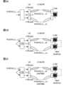
- FIG. 1A and 1B are diagrams illustrating an example of a single panel UL transmission.
- 2A to 2C are diagrams showing examples of methods 1 to 3 of simultaneous UL transmission using multiple panels.
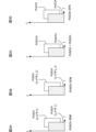
- 3A-3D are diagrams illustrating an example of single-DCI (S-DCI)/multiple-DCI (M-DCI) based multi-panel simultaneous UL transmission (STxMP).
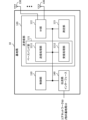
- FIG. 4 is a diagram showing an example in which the PUCCH and multiple PUSCHs overlap in time.
- FIG. 5 is a flowchart illustrating an example of a process according to the first embodiment.
- FIG. 6 is a diagram illustrating an example of a schematic configuration of a wireless communication system according to an embodiment.
- FIG. 7 is a diagram illustrating an example of the configuration of a base station according to an embodiment.
- FIG. 8 is a diagram illustrating an example of the configuration of a user terminal according to an embodiment.
- FIG. 9 is a diagram illustrating an example of the hardware configuration of a base station and a user terminal according to an embodiment.
- FIG. 10 is a diagram illustrating an example of a vehicle according to an embodiment.
- At least one of the following transmission schemes A and B may be applied to the single panel UL transmission scheme or the single panel UL transmission scheme candidate.
- the panel/UE panel may be read as a UE capability value set (e.g., UE capability value set), capability index, index, etc. reported for each UE capability.
- UE capability value set e.g., UE capability value set
- capability index e.g., index, etc. reported for each UE capability.
- different panels, different spatial relationships, different joint TCI states, different TPC parameters, different antenna ports, etc. may be read as mutually interchangeable terms.
- ⁇ Transmission method A Single panel, single TRP, UL transmission>
- a transmission scheme is used in which a UE transmits UL for one TRP from only one beam and panel at one time (FIG. 1A).
- ⁇ Transmission method B Single panel multi-TRP UL transmission> In Rel. 17, UL transmission from only one beam and panel at one time and repeated transmission to multiple TRPs is considered (FIG. 1B).
- the UE transmits PUSCH from panel #1 to TRP #1 (switching beams and panels), and then transmits PUSCH from panel #2 to TRP #2.
- the two TRPs are connected via an ideal backhaul.
- Multi-panel transmission In Rel. 18 and later, in order to improve UL throughput/reliability, support for simultaneous UL transmission using multiple panels (e.g., simultaneous multi-panel UL transmission (STxMP)) for one or more TRPs is being considered. Also, a multi-panel UL transmission scheme is being considered for a specific UL channel (e.g., PUSCH/PUCCH) etc.
- STxMP simultaneous multi-panel UL transmission
- codebooks of existing systems e.g., before Rel. 16
- multi-panel UL transmission method or a candidate multi-panel UL transmission method at least one of the following methods 1 to 3 (multi-panel UL transmission methods 1 to 3) is being considered. Only one of transmission methods 1 to 3 may be supported. Multiple methods including at least one of transmission methods 1 to 3 may be supported, and one of the multiple transmission methods may be configured in the UE.
- ⁇ Transmission method 1 Coherent multi-panel UL transmission> Multiple panels may be synchronized with each other. All layers are mapped to all panels. Multiple analog beams are directed.
- the SRS Resource Indicator (SRI) field may be extended. This scheme may use up to 4 layers for the UL.
- the UE maps one codeword (CW) or one transport block (TB) to L layers (PUSCH (1, 2, ..., L)) and transmits L layers from each of the two panels.
- Panel #1 and panel #2 are coherent. Transmission method 1 can obtain diversity gain.
- the total number of layers in the two panels is 2L. If the maximum total number of layers is 4, the maximum number of layers in one panel is 2.
- ⁇ Transmission method 2 Non-coherent multi-panel UL transmission of one codeword (CW) or transport block (TB)> Multiple panels may not be synchronized. Different layers are mapped to different panels and one CW or TB for PUSCH from multiple panels. A layer corresponding to one CW or TB may be mapped to multiple panels.
- the transmission scheme may use up to 4 layers or up to 8 layers for UL. If up to 8 layers are supported, the transmission scheme may support one CW or TB with up to 8 layers.
- the UE maps 1 CW or 1 TB to k layers (PUSCH(1, 2, ..., k)) and L-k layers (PUSCH(k+1, k+2, ..., L)), transmits k layers from panel #1, and transmits L-k layers from panel #2.
- Transmission method 2 can obtain gains through multiplexing and diversity. The total number of layers in the two panels is L.
- ⁇ Transmission method 3 Non-coherent multi-panel UL transmission of two CWs or TBs> Multiple panels may not be synchronized. Different layers are mapped to different panels and two CWs or TBs for PUSCH from multiple panels. Layers corresponding to one CW or TB may be mapped to one panel. Layers corresponding to multiple CWs or TBs may be mapped to different panels. This transmission scheme may use up to 4 layers or up to 8 layers for UL. When supporting up to 8 layers, this transmission scheme may support up to 4 layers per CW or TB.
- the UE maps CW#1 or TB#1 of the 2CWs or 2TBs to k layers (PUSCH (1, 2, ..., k)), maps CW#2 or TB#2 to L-k layers (PUSCH (k+1, k+2, ..., L)), transmits k layers from panel #1, and transmits L-k layers from panel #2.
- Transmission method 3 can obtain gains through multiplexing and diversity. The total number of layers in the two panels is L.
- the base station may configure or indicate panel-specific transmission for UL transmission using UL TCI or panel ID.
- UL TCI (UL TCI state) may be based on signaling similar to DL beam indication supported in Rel. 15.
- Panel ID may be implicitly or explicitly applied to transmission of at least one of target RS resource or target RS resource set, PUCCH, SRS, and PRACH. If panel ID is explicitly signaled, panel ID may be configured in at least one of target RS, target channel, and reference RS (e.g., DL RS resource configuration or spatial relationship information).
- multi-panel UL transmission e.g., Simultaneous Transmission across Multiple Panels (STxMP)
- STxMP Simultaneous Transmission across Multiple Panels
- S-DCI Single DCI
- M-DCI Multiple DCI
- STxMP simultaneous multi-panel UL transmission
- SDM Space Division Multiplexing
- SFN Single Frequency Network
- the UE transmits one (same) PUSCH simultaneously from different panels, all corresponding to the same layer/DMRS port.
- the UE may transmit the same signal in one or more same resource elements (REs) from each panel with different joint/UL TCI states.
- M-DCI PUSCH+PUSCH (overlap) scheme (FIG. 3C): The UE simultaneously transmits two PUSCHs that overlap in time from different panels.
- S-DCI PUCCH SFN Scheme (FIG. 3D): The UE transmits one (same) PUCCH simultaneously from different panels.
- the number of layers that can be transmitted across two panels may be a maximum of four layers, or may be more than four layers.
- S-DCI PUSCH SDM/SFN Scheme (FIGS. 3A and 3B): In DCI, two SRS resource sets are configured, and two SRI fields/Transmitted Precoding Matrix Indicator (TPMI) fields are indicated.
- M-DCI PUSCH+PUSCH scheme (FIG. 3C): Two SRS resource sets are configured in a DCI, and each DCI/PUSCH is associated with two CORESET pool indices (CORESETPoolIndex).
- S-DCI PUCCH SFN scheme (FIG. 3D): Two TCI states are applied to one PUCCH resource.
- the UE may assume that repeated SDM PUSCH transmissions are scheduled on the same time and frequency resources. That is, the UE may transmit repeated SDM PUSCH transmissions on the same time and frequency resources when using coherent panels.
- PUSCH transmission using SDM may be configured such that at least a portion of the time and frequency resources overlap.
- a UE may simultaneously transmit two independent PUSCHs associated with different TRPs in the same active BWP.
- the M-DCI PUSCH+PUSCH method means simultaneous transmission of multiple PUSCHs, but simultaneous transmission of PUSCHs and PUCCHs may also be supported.
- a method of multiplexing/mapping UCI is being considered for cases where one PUCCH overlaps with multiple PUSCHs in simultaneous transmission of PUSCH and PUCCH.
- the multiple PUSCHs may be multiple PUSCHs transmitted simultaneously. In this case, the multiple PUSCHs may be associated with different TRPs/panels.
- Restrictions A to C are applied to cases where the PUCCH and the PUSCH (e.g., multiple PUSCHs) overlap (FIG. 4).
- the UE when a PUCCH (including UCI) overlaps with multiple PUSCHs and AP-CSI is not multiplexed/mapped to any of the multiple PUSCHs, the UE multiplexes/maps the UCI to the PUSCH of the serving cell with the smallest serving cell index (ServCellIndex). In this case, if there are multiple PUSCHs for the serving cell with the smallest serving cell index, the UE multiplexes/maps the UCI to the earliest PUSCH (Restriction B).
- the UE does not assume/expect one or more PUSCHs containing AP-CSI to overlap with the PUCCH (Restriction C).
- Simultaneous transmission using multiple panels for multiple (e.g., two) PUSCHs/PUCCHs may be supported/configured/enabled.
- the UE may support simultaneous transmission using multiple panels for multiple (e.g., two) PUSCHs/PUCCHs.
- the UE may be configured/enabled simultaneous transmission using multiple panels for multiple (e.g., two) PUSCHs/PUCCHs.
- This setting/activation may be performed using higher layer signaling (RRC/MAC CE)/DCI.
- RRC/MAC CE higher layer signaling
- the PUCCH and multiple PUSCHs may be configured to overlap (in the time domain).
- the multiple PUSCHs may be PUSCHs that satisfy the conditions for multiplexing/mapping of UCI.
- the UE may determine whether to transmit a PUSCH/PUCCH (UCI) based on whether the PUCCH/multiple PUSCHs are associated with the same panel or different panels.
- UCI PUSCH/PUCCH
- the UE may select/determine a specific PUSCH from the multiple PUSCHs based on a specific rule.
- the specific rule may be a PUSCH within the restrictions specified in the above Rel. 16/17.
- the UE may multiplex/map the UCI to the selected/determined PUSCH.
- the UE may select/determine a specific PUSCH from the multiple PUSCHs based on a specific rule.
- the specific rule may be a PUSCH within the restrictions specified in the above Rel. 16/17.
- the UE may multiplex/map UCI to the selected/determined PUSCH.
- the UE may select/determine a specific PUSCH from the multiple PUSCHs based on a specific rule.
- the UE may multiplex/map UCI to the selected/determined PUSCH.
- the particular rule may be at least one of the following options 1 to 5:
- the UE may make a selection/decision (first selection/decision) for multiple PUSHs based on an ID related to a panel (panel ID).
- the UE may select/determine a PUSCH that corresponds to a particular panel ID, or a PUSCH that is associated with the same panel as a PUCCH that corresponds to a particular priority.
- the ID for that particular panel may be a lower (or higher) panel ID.
- the PUCCH corresponding to that particular priority may be a PUCCH corresponding to a higher (or lower) priority.
- higher, greater than, lower, smaller, highest, maximum, lowest, and smallest may be interpreted as interchangeable.
- higher, greater than, lower, and smaller may be interpreted as highest, maximum, lowest, and smallest.
- the UE may apply the rules in the above Rel. 16/17 to the PUSCH (e.g., first, a selection/decision based on the type of PUSCH, second, a selection/decision based on the serving cell index, and third, a selection/decision regarding the time resources of the PUSCH).
- the UE may make a selection/decision (first selection/decision) for multiple PUSHs based on the type of the PUSH.
- a priority may be applied based on whether the PUSCH is scheduled by DCI or a configured grant PUSCH.
- the priority of the PUSCH scheduled by DCI may be specified to be higher (or lower) than the priority of the configured grant PUSCH.
- the UE may select/determine the PUSCH based on the priority.
- the UE may make a selection/decision (second selection/decision) based on the panel ID for the PUSCHs based on the first selection/decision.
- the UE may select/determine from the selected/determined PUSCHs a PUSCH that corresponds to an ID (panel ID) for a specific panel, or a PUSCH that is associated with the same panel as a PUCCH that corresponds to a specific priority.
- the ID for that particular panel may be a lower (or higher) panel ID.
- the PUCCH corresponding to that particular priority may be a PUCCH corresponding to a higher (or lower) priority.
- the UE may make a selection/decision (third selection/decision) based on the serving cell index (ServCellIndex) corresponding to the PUSCH.
- the UE may select/determine a PUSCH corresponding to a specific serving cell index (ServCellIndex) from the selected/determined PUSCHs. For example, the priority of a PUSCH with a smaller serving cell index (ServCellIndex) may be specified to be higher (or lower) than a PUSCH with a larger serving cell index (ServCellIndex). The UE may select/determine a PUSCH based on the priority.
- a serving cell index For example, the priority of a PUSCH with a smaller serving cell index (ServCellIndex) may be specified to be higher (or lower) than a PUSCH with a larger serving cell index (ServCellIndex).
- the UE may select/determine a PUSCH based on the priority.
- the UE may select/decide the earliest (or latest) PUSCH from among the multiple PUSCHs (fourth selection/decision). For example, the priority of an earlier PUSCH may be set higher (or lower) than the priority of a later PUSCH.
- the UE may make a selection/decision (first selection/decision) for multiple PUSHs based on the type of the PUSH.
- a priority may be applied based on whether the PUSCH is scheduled by DCI or a configured grant PUSCH.
- the priority of the PUSCH scheduled by DCI may be specified to be higher (or lower) than the priority of the configured grant PUSCH.
- the UE may select/determine the PUSCH based on the priority.
- the UE may make a selection/decision (second selection/decision) based on the serving cell index (ServCellIndex) corresponding to the PUSCH.
- the UE may select/determine a PUSCH corresponding to a specific serving cell index (ServCellIndex) from the selected/determined PUSCHs. For example, the priority of a PUSCH with a smaller serving cell index (ServCellIndex) may be specified to be higher (or lower) than a PUSCH with a larger serving cell index (ServCellIndex). The UE may select/determine a PUSCH based on the priority.
- a serving cell index For example, the priority of a PUSCH with a smaller serving cell index (ServCellIndex) may be specified to be higher (or lower) than a PUSCH with a larger serving cell index (ServCellIndex).
- the UE may select/determine a PUSCH based on the priority.
- the UE may make a selection/decision (third selection/decision) based on the panel ID for the PUSCHs based on the second selection/decision.
- the UE may select/determine from the selected/determined PUSCHs a PUSCH that corresponds to an ID (panel ID) for a specific panel, or a PUSCH that is associated with the same panel as a PUCCH that corresponds to a specific priority.
- the ID for that particular panel may be a lower (or higher) panel ID.
- the PUCCH corresponding to that particular priority may be a PUCCH corresponding to a higher (or lower) priority.
- the UE may select/decide the earliest (or latest) PUSCH from among the multiple PUSCHs (fourth selection/decision). For example, the priority of an earlier PUSCH may be set higher (or lower) than the priority of a later PUSCH.
- the UE may make a selection/decision (first selection/decision) for multiple PUSHs based on the type of the PUSH.
- a priority may be applied based on whether the PUSCH is scheduled by DCI or a configured grant PUSCH.
- the priority of the PUSCH scheduled by DCI may be specified to be higher (or lower) than the priority of the configured grant PUSCH.
- the UE may select/determine the PUSCH based on the priority.
- the UE may make a selection/decision (second selection/decision) based on the serving cell index (ServCellIndex) corresponding to the PUSCH.
- the UE may select/determine a PUSCH corresponding to a specific serving cell index (ServCellIndex) from the selected/determined PUSCHs. For example, the priority of a PUSCH with a smaller serving cell index (ServCellIndex) may be specified to be higher (or lower) than a PUSCH with a larger serving cell index (ServCellIndex). The UE may select/determine a PUSCH based on the priority.
- a serving cell index For example, the priority of a PUSCH with a smaller serving cell index (ServCellIndex) may be specified to be higher (or lower) than a PUSCH with a larger serving cell index (ServCellIndex).
- the UE may select/determine a PUSCH based on the priority.
- the UE may select/decide the earliest (or latest) PUSCH from among the multiple PUSCHs (third selection/decision). For example, the priority of an earlier PUSCH may be set higher (or lower) than the priority of a later PUSCH.
- the UE may make a selection/decision (fourth selection/decision) based on the panel ID for the PUSHs based on the third selection/decision.
- the UE may select/determine from the selected/determined PUSCHs a PUSCH that corresponds to an ID (panel ID) for a specific panel, or a PUSCH that is associated with the same panel as a PUCCH that corresponds to a specific priority.
- the ID for that particular panel may be a lower (or higher) panel ID.
- the PUCCH corresponding to that particular priority may be a PUCCH corresponding to a higher (or lower) priority.
- the UE may select/decide on the PUSCH corresponding to each panel by applying the rules in the above Rel. 16/17 (e.g., firstly, a selection/decision based on the type of PUSCH, secondly, a selection/decision based on the serving cell index, and thirdly, a selection/decision regarding the time resource of the PUSCH).
- the rules in the above Rel. 16/17 e.g., firstly, a selection/decision based on the type of PUSCH, secondly, a selection/decision based on the serving cell index, and thirdly, a selection/decision regarding the time resource of the PUSCH.
- the UE may use multiple panels to multiplex/map UCI to multiple PUSCHs.
- Different rules/conditions e.g., at least one of options 1 to 5 above
- Different rules/conditions e.g., at least one of options 1 to 5 above
- Different rules/conditions for selecting/determining one of the multiple PUSCHs may be applied based on a specific condition.
- the particular condition may be, for example, at least one of the following: - Configuration of certain higher layer (RRC) parameters. Whether a parameter (eg, ackNackFeedbackMode) is provided/configured to indicate a HARQ-ACK feedback mode indicating a particular value (eg, separate or joint). Whether the PUCCH is semi-statically configured by the RRC/MAC CE or dynamically triggered by the DCI. Whether PUSCH is semi-statically configured by RRC/MAC CE or dynamically triggered by DCI. Whether the PUSCH associated to the same panel as the PUCCH is semi-statically configured by the RRC/MAC CE or dynamically triggered by DCI. - Whether the PUSCH associated with a different panel than the PUCCH is semi-statically configured by the RRC/MAC CE or dynamically triggered by the DCI.
- RRC higher layer
- the UE may assume/determine that any rule/condition applies when a parameter (e.g., ackNackFeedbackMode) indicating a HARQ-ACK feedback mode indicating a particular value (e.g., joint) is provided/configured.
- a parameter e.g., ackNackFeedbackMode
- HARQ-ACK feedback mode indicating a particular value (e.g., joint) is provided/configured.
- the UE may assume/determine that a PUSCH associated with the same panel as a PUCCH (always) has a higher priority.
- a parameter e.g., ackNackFeedbackMode
- a specific value e.g., separate
- the UE may assume/determine that any rules/conditions apply in the case of semi-static configuration/schedule.
- the UE may assume/determine that in the case of dynamic indication/scheduling, the PUSCH associated with the same panel as the PUCCH (always) has higher priority.
- the UE can appropriately select/decide the PUSCH to which UCI is multiplexed/mapped from multiple PUSCHs, even when performing simultaneous UL transmission using multiple panels.
- An antenna group may be referred to as a coherent group.
- a coherent group may include one or more coherent ports.
- a partially coherent UE may have multiple coherent groups.
- Antenna ports within a coherent group may be coherent.
- Antenna ports between different coherent groups may not be coherent.
- Each coherent group may correspond to a different transmit panel/Tx chain/SRS resource set/RS resource set/spatial relation info/joint Transmission Configuration Indication state/UL TCI state/received TRP.
- the SRS resource set may specifically correspond to a codebook or non-codebook SRS resource set.
- each coherent group may correspond to a different received TRP.
- the coherent groups may be called coherent antenna groups, port groups, antenna sets, etc.
- the UE may report the supported antenna groups/antenna configuration information/coherent number as UE capability information.
- the UE may also configure the coherent groups (e.g., the number of coherent groups, the number of ports included in each coherent group) by higher layer signaling.
- a codeword is a sequence (set) of coded bits generated based on a TB.
- a CW can also be considered as a TB with error protection function.
- simultaneous UL transmission e.g., PUSCH transmission
- simultaneous PUSCH transmission of multiple beams/panels may correspond to PUSCH transmission with a number of layers greater than four, or may correspond to PUSCH transmission with a number of layers less than four.
- precoding matrices for UL transmissions using more than four antenna ports are being considered.
- a codebook for eight-port transmission (which may be called an 8 Transmission (TX) UL codebook) is being considered.
- a UE will support STxMP transmission of multiple PUSCHs.
- a PUCCH e.g., including UCI
- the inventors therefore came up with a way to solve these problems.
- A/B and “at least one of A and B” may be interpreted as interchangeable. Also, in this disclosure, “A/B/C” may mean “at least one of A, B, and C.”
- Radio Resource Control RRC
- RRC parameters RRC parameters
- RRC messages higher layer parameters, fields, information elements (IEs), settings, etc.
- IEs information elements
- CE Medium Access Control
- update commands activation/deactivation commands, etc.
- the higher layer signaling may be, for example, any one of Radio Resource Control (RRC) signaling, Medium Access Control (MAC) signaling, broadcast information, other messages (e.g., messages from the core network such as positioning protocols (e.g., NR Positioning Protocol A (NRPPa)/LTE Positioning Protocol (LPP)) messages), or a combination of these.
- RRC Radio Resource Control
- MAC Medium Access Control
- LPP LTE Positioning Protocol
- the MAC signaling may use, for example, a MAC Control Element (MAC CE), a MAC Protocol Data Unit (PDU), etc.
- the broadcast information may be, for example, a Master Information Block (MIB), a System Information Block (SIB), Remaining Minimum System Information (RMSI), Other System Information (OSI), etc.
- MIB Master Information Block
- SIB System Information Block
- RMSI Remaining Minimum System Information
- OSI System Information
- the physical layer signaling may be, for example, Downlink Control Information (DCI), Uplink Control Information (UCI), etc.
- DCI Downlink Control Information
- UCI Uplink Control Information
- the terms drop, abort, cancel, puncture, rate match, postpone, do not transmit, etc. may be read as interchangeable terms.
- the terms index, number, and ID may be read as interchangeable terms.
- multi-TRP, multi-TRP system, multi-TRP transmission, multi-PDSCH, channel using multi-TRP, channel using multiple TCI states/spatial relationships, multi-TRP enabled by RRC/DCI, multiple TCI states/spatial relationships enabled by RRC/DCI, and at least one of multi-TRP based on a single DCI and multi-TRP based on multiple DCI may be read as interchangeable.
- multi-TRP based on a multi-DCI (M-DCI), and a CORESET pool index (CORESETPoolIndex) value of 1 is set for the CORESET may be read as interchangeable.
- multi-TRP based on a single DCI, and at least one code point in the TCI field is mapped to two TCI states may be read as interchangeable.
- single TRP, single DCI (S-DCI), single PDCCH, multi-TRP based on single DCI, single TRP system, single TRP transmission, single PDSCH, channel using single TRP, channel using one TCI state/spatial relationship, multi-TRP not being enabled by RRC/DCI, multiple TCI states/spatial relationships not being enabled by RRC/DCI, a CORESETPoolIndex value of 1 not being set for any CORESET and no code point in the TCI field being mapped to two TCI states, and two TCI states on at least one TCI code point being activated may be read as interchangeable.
- multi-DCI M-DCI
- RRC parameter "coresetPoolIndex” a CORESET pool index
- RRC parameter "coresetPoolIndex” a CORESET pool index
- RRC parameter "coresetPoolIndex" a CORESET pool index
- RRC parameter "coresetPoolIndex" a CORESET pool index of a second value (e.g., 1).
- TX transmission
- port antenna port
- layer rank, etc.
- a port/antenna port may mean a port/antenna port for UL (e.g., SRS/PUSCH) transmission.
- an SRS resource set and a resource set may be interchangeable.
- a coherent group and an SRS resource set may be interchangeable.
- 8TX This disclosure describes an example of 8TX, but the same applies to 5TX, 6TX, 7TX, 8 or more TX, 4 or less TX, etc. in the same way as for 8TX.
- “8” may be read as “n (n is any integer),” and in this case, the number of layers/ports, etc., described assuming the maximum value of “8” can be appropriately read as assuming the maximum value of "n” by a person skilled in the art.
- the application of one code word and the number of layers being four or less may be interpreted as interchangeable.
- the application of two code words and the number of layers being greater than four may be interpreted as interchangeable.
- panel, panel ID, UE capability value set e.g., UE capability value set
- UE capability value e.g., UE capability value
- capability index TRP SRS resource set
- CORESET pool index capability index
- beam group TCI state group
- spatial relationship group reference signal group
- path loss RS group path loss RS group
- STxMP simultaneous transmission using multiple panels
- transmission using multiple panels in at least the same time resource/domain, etc. may be interpreted as interchangeable.
- the transmission may mean simultaneous transmission of multiple PUSCHs.
- overlapping PUCCH/PUSCH may mean that some or all of the PUCCH/PUSCH overlap in time.
- the UE may transmit UE capability information indicating that it supports multi-panel PUSCH+PUSCH, and may receive configuration/instructions regarding multi-panel PUSCH+PUSCH from the base station (gNB) via higher layer signaling/physical layer signaling.
- gNB base station
- the UE selects one prioritized PUSCH based on certain rules shown below, and transmits the selected PUSCH with UCI multiplexed. In this case, the UE may stop transmitting the PUCCH. For example, the UE may select one prioritized PUSCH based on at least one of the Modulation and Coding Scheme (MCS), transport block (TB) size, rank, TB (or CW) number (ID), and panel ID that correspond/associate with the multiple PUSCHs.
- MCS Modulation and Coding Scheme
- TB transport block
- ID panel ID
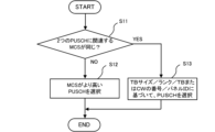
- FIG. 5 is a flowchart showing an example of the processing of the first embodiment.
- the UE selects one PUSCH with a higher MCS (or a larger TB size, or a higher (or lower) rank) (S12).
- the UE may select the one PUSCH based on at least one of the TB size, rank, TB (or CW) number (ID), and panel ID corresponding to the multiple PUSCHs (S13).
- the rules of options 1-1 to 1-3 below may be applied.
- higher, greater than, lower, smaller, highest, maximum, lowest, and smallest may be interpreted as interchangeable.
- two PUSCHs may be interpreted as multiple (e.g., three or more) PUSCHs. In that case, higher, greater than, lower, and smaller may be interpreted as highest, maximum, lowest, and smallest.
- the PUSCH with the larger TB size is prioritized. If the two PUSCHs have the same TB size, the PUSCH associated with the higher MCS (or higher rank (or lower rank)) is prioritized.
- the UE multiplexes UCI onto both PUSCHs (all PUSCHs) and transmits them.
- the UE may apply any of the above options 1-1, 1-2-1, 1-2-2, or 1-3 to determine the prioritized PUSCH without comparing MCS.
- the UE may receive a setting/instruction of the priority corresponding to the PUSCH/panel through higher layer signaling/physical layer signaling. Based on the setting/instruction, the UE may multiplex and transmit UCI onto a PUSCH with a higher priority or onto a PUSCH corresponding to a panel with a higher priority.
- the UE may use at least one of the following elements as a rule for selecting a PUSCH on which UCI is multiplexed: MCS, TBS, rank, panel ID, and the above-mentioned Rel. 16/17 conditions (i.e., DCI-based scheduling has a higher priority than a configuration grant, the smaller the serving cell index, the higher the priority, and the earlier the PUSCH has a higher priority).
- the application order of each element may be predefined in the specification, or may be configured/instructed to the UE by higher layer signaling/physical layer signaling.
- the UE first compares the MCS of the two PUSCHs and selects the PUSCH associated with the higher MCS. If the MCS of the two PUSCHs are the same, the UE compares the panel IDs and selects the PUSCH associated with the lower panel ID.
- the UE first compares the MCS of the two PUSCHs and selects the PUSCH associated with the higher MCS. If the MCS of the two PUSCHs are the same, the UE compares the TB sizes of the two PUSCHs and selects the PUSCH with the larger TB size. If the TB sizes of the two PUSCHs are the same, the UE compares the panel IDs associated with the two PUSCHs and selects the PUSCH associated with the lower panel ID.
- the UE first compares the TB sizes of the two PUSCHs and selects the PUSCH with the larger TB size. If the TB sizes of the two PUSCHs are the same, the UE compares the MCS of the two PUSCHs and selects the PUSCH associated with the higher MCS. If the MCS of the two PUSCHs are the same, the UE compares the panel IDs associated with the two PUSCHs and selects the PUSCH associated with the lower panel ID.
- the elements used to select the PUSCH on which the UCI is multiplexed and the order of application are not limited to the above example, and elements/orders of application different from the above example may be used.
- the UE can select the PUSCH on which the UCI is multiplexed using at least one element of the MCS, TBS, rank, TB (or CW) number (ID), panel ID, and the above-mentioned Rel. 16/17 conditions.
- the UE may use a layer and a CW ID as a rule for selecting a CW of a PUSCH in which UCI is multiplexed, in addition to the elements of Variation 1. That is, the UE may select a CW/TB in which UCI is multiplexed (a PUSCH corresponding to a CW/TB) based on at least one element of MCS, TB size, rank, TB number (ID), panel ID, layer, CW ID, and the above-mentioned conditions of Rel. 16/17 corresponding to multiple PUSCHs (for each parameter of one or more codewords/TBs).
- the UE first compares the TB sizes corresponding to the two CWs and selects the CW associated with the larger TB size. If the TB sizes of the two CWs are the same, the UE compares the MCSs associated with the two CWs and selects the PUSCH associated with the larger MCS. If the MCSs of the two CWs are the same, the UE compares the CW IDs associated with the two CWs and selects the CW with the lower CW ID (e.g., CW#0).
- the UE first compares the layers of the two CWs and selects the CW associated with the larger layer. For example, if there is a two-layer CW and a three-layer CW, the UE selects the three-layer CW. Then, if the layers of the two CWs are the same, the UE compares the CW IDs associated with the two CWs and selects the CW with the lower CW ID (e.g., CW#0).
- the lower CW ID e.g., CW#0
- the elements used to select the PUSCH on which the UCI is multiplexed and the order of application are not limited to the above example, and elements/orders of application different from the above example may be used.
- the UE can select the PUSCH on which the UCI is multiplexed using at least one element of the MCS, TB size, rank, TB number (ID), panel ID, layer, CW ID, and the above-mentioned Rel. 16/17 conditions.
- a PUSCH on which UCI is multiplexed can be appropriately selected. For example, when an 8-port transmission (8Tx) UL is applied, a UE can select a PUSCH with better performance by multiplexing UCI into a codeword (CW) with a higher MCS.
- 8Tx 8-port transmission
- This embodiment may be applied in combination with the first embodiment. That is, it may be applied to a case where S-DCI or M-DCI-based multi-panel PUSCH+PUSCH (simultaneous transmission of multiple PUSCHs using multiple panels) is supported. And, when PUCCH overlaps with multiple PUSCHs, the UE may select one PUSCH with priority based on a specific rule in the first embodiment, and multiplex UCI on the selected PUSCH and transmit it.
- Different rules/conditions for selecting/determining one PUSCH among multiple PUSCHs may be applied based on the following specific conditions:
- the particular condition may be, for example, at least one of the following: - Configuration of certain higher layer (RRC) parameters. Whether a parameter (eg, ackNackFeedbackMode) is provided/configured to indicate a HARQ-ACK feedback mode indicating a particular value (eg, separate or joint). Whether the PUCCH is semi-statically configured by the RRC/MAC CE or dynamically triggered by the DCI. Whether PUSCH is semi-statically configured by RRC/MAC CE or dynamically triggered by DCI. For example, whether the PUSCH associated with the same panel as the PUCCH is semi-statically configured by the RRC/MAC CE or dynamically triggered by a DCI. For example, whether the PUSCH associated with a different panel than the PUCCH is semi-statically configured by the RRC/MAC CE or dynamically triggered by a DCI. Setting/instruction/application of each method applied to the STxMP described above.
- RRC higher layer
- MCS, TBS, or rank/layer based PUSCH selection may only be applicable to ideal backhaul.
- the UE may assume/determine that at least one rule/condition of this embodiment applies when a parameter (e.g., ackNackFeedbackMode) indicating a HARQ-ACK feedback mode indicating a particular value (e.g., joint) is provided/configured.
- a parameter e.g., ackNackFeedbackMode
- HARQ-ACK feedback mode indicating a particular value (e.g., joint) is provided/configured.
- the UE may assume/determine that a PUSCH associated with the same panel as a PUCCH (always) has a higher priority when a parameter (e.g., ackNackFeedbackMode) indicating a HARQ-ACK feedback mode indicating a specific value (e.g., separate) is provided/configured.
- a parameter e.g., ackNackFeedbackMode
- a HARQ-ACK feedback mode indicating a specific value (e.g., separate) is provided/configured.
- the association of the PUSCH/PUCCH with a panel may be based on at least one of the following: Specific configuration within the PUCCH resource. - Specific settings within the configuration grant settings for configuration grant PUSCH (CG-PUSCH). An SRS resource set associated with the PUSCH and an association between the SRS resource set and a panel. CORESET pool index of scheduling/triggering DCI for PUCCH/PUSCH. - TCI state/QCL source RS of scheduling/triggering DCI of PUCCH/PUSCH and association between TCI state/QCL source RS and panel.
- TCI state/spatial relationship information/QCL source RS/path loss RS/timing advance group (TAG) of PUSCH/PUCCH and association between TCI state/spatial relationship information/QCL source RS/path loss RS/TAG of PUSCH/PUCCH and panel.
- the second embodiment it is possible to appropriately select/determine a PUSCH for multiplexing/mapping UCI from multiple PUSCHs.
- panel/TRP/SRS resource set/COREST pool index/beam group/TCI state group/spatial relationship group/RS group/path loss RS group may be interpreted as interchangeable.
- any information may be notified to the UE (from a network (NW) (e.g., a base station (BS))) (in other words, any information is received by the UE from the BS) using physical layer signaling (e.g., DCI), higher layer signaling (e.g., RRC signaling, MAC CE), a specific signal/channel (e.g., PDCCH, PDSCH, reference signal), or a combination thereof.
- NW network
- BS base station
- the MAC CE may be identified by including a new Logical Channel ID (LCID) in the MAC subheader that is not specified in existing standards.
- LCID Logical Channel ID
- the notification may be made by a specific field of the DCI, a Radio Network Temporary Identifier (RNTI) used to scramble Cyclic Redundancy Check (CRC) bits assigned to the DCI, the format of the DCI, etc.
- RNTI Radio Network Temporary Identifier
- CRC Cyclic Redundancy Check
- notification of any information to the UE in the above-mentioned embodiments may be performed periodically, semi-persistently, or aperiodically.
- notification of any information from the UE (to the NW) may be performed using physical layer signaling (e.g., UCI), higher layer signaling (e.g., RRC signaling, MAC CE), a specific signal/channel (e.g., PUCCH, PUSCH, PRACH, reference signal), or a combination thereof.
- physical layer signaling e.g., UCI
- higher layer signaling e.g., RRC signaling, MAC CE
- a specific signal/channel e.g., PUCCH, PUSCH, PRACH, reference signal
- the MAC CE may be identified by including a new LCID in the MAC subheader that is not specified in existing standards.
- the notification may be transmitted using PUCCH or PUSCH.
- notification of any information from the UE may be performed periodically, semi-persistently, or aperiodically.
- At least one of the above-mentioned embodiments may be applied when a specific condition is satisfied, which may be specified in a standard or may be notified to a UE/BS using higher layer signaling/physical layer signaling.
- At least one of the above-described embodiments may be applied only to UEs that have reported a particular UE capability or that support the particular UE capability. Note that “supporting” and “whether to support” may be interpreted as interchangeable.
- the particular UE capability may indicate at least one of the following: - Supporting specific processing/operations/control/information for at least one of the above embodiments. Whether the UE supports the STxMP PUSCH+PUSCH (e.g., M-DCI PUSCH+PUSCH) scheme. Whether at least one of 2CW, rank greater than 4, and 8TX PUSCH is supported.
- STxMP PUSCH+PUSCH e.g., M-DCI PUSCH+PUSCH
- the above-mentioned specific UE capabilities may be capabilities that are applied across all frequencies (commonly regardless of frequency), capabilities per frequency (e.g., one or a combination of a cell, band, band combination, BWP, component carrier, etc.), capabilities per frequency range (e.g., Frequency Range 1 (FR1), FR2, FR3, FR4, FR5, FR2-1, FR2-2), capabilities per subcarrier spacing (SubCarrier Spacing (SCS)), or capabilities per Feature Set (FS) or Feature Set Per Component-carrier (FSPC).
- FR1 Frequency Range 1
- FR2 FR2, FR3, FR4, FR5, FR2-1, FR2-2
- SCS subcarrier Spacing
- FS Feature Set
- FSPC Feature Set Per Component-carrier
- the specific UE capabilities may be capabilities that are applied across all duplexing methods (commonly regardless of the duplexing method), or may be capabilities for each duplexing method (e.g., Time Division Duplex (TDD) and Frequency Division Duplex (FDD)).
- TDD Time Division Duplex
- FDD Frequency Division Duplex
- At least one of the above-mentioned embodiments may be applied when the UE configures/activates/triggers specific information related to the above-mentioned embodiments (or performs the operations of the above-mentioned embodiments) by higher layer signaling/physical layer signaling.
- the specific information may be any RRC parameters for a specific release (e.g., Rel. 18/19), etc.
- the UE may apply, for example, the behavior of Rel. 15/16/17.
- a control unit that selects one PUSCH from the plurality of PUSCHs based on a specific rule when simultaneous transmission of the plurality of PUSCHs using a multi-panel is supported and a PUCCH overlaps with the plurality of PUSCHs;
- a transmitter that multiplexes uplink control information (UCI) onto the one selected PUSCH and transmits the multiplexed information;
- a terminal having the above configuration.
- Wired communication system A configuration of a wireless communication system according to an embodiment of the present disclosure will be described below.
- communication is performed using any one of the wireless communication methods according to the above embodiments of the present disclosure or a combination of these.
- FIG. 6 is a diagram showing an example of a schematic configuration of a wireless communication system according to an embodiment.
- the wireless communication system 1 (which may simply be referred to as system 1) may be a system that realizes communication using Long Term Evolution (LTE) specified by the Third Generation Partnership Project (3GPP), 5th generation mobile communication system New Radio (5G NR), or the like.
- LTE Long Term Evolution
- 3GPP Third Generation Partnership Project
- 5G NR 5th generation mobile communication system New Radio
- the wireless communication system 1 may also support dual connectivity between multiple Radio Access Technologies (RATs) (Multi-RAT Dual Connectivity (MR-DC)).
- MR-DC may include dual connectivity between LTE (Evolved Universal Terrestrial Radio Access (E-UTRA)) and NR (E-UTRA-NR Dual Connectivity (EN-DC)), dual connectivity between NR and LTE (NR-E-UTRA Dual Connectivity (NE-DC)), etc.
- RATs Radio Access Technologies
- MR-DC may include dual connectivity between LTE (Evolved Universal Terrestrial Radio Access (E-UTRA)) and NR (E-UTRA-NR Dual Connectivity (EN-DC)), dual connectivity between NR and LTE (NR-E-UTRA Dual Connectivity (NE-DC)), etc.
- E-UTRA Evolved Universal Terrestrial Radio Access
- EN-DC E-UTRA-NR Dual Connectivity
- NE-DC NR-E-UTRA Dual Connectivity
- the LTE (E-UTRA) base station (eNB) is the master node (MN), and the NR base station (gNB) is the secondary node (SN).
- the NR base station (gNB) is the MN, and the LTE (E-UTRA) base station (eNB) is the SN.
- the wireless communication system 1 may support dual connectivity between multiple base stations within the same RAT (e.g., dual connectivity in which both the MN and SN are NR base stations (gNBs) (NR-NR Dual Connectivity (NN-DC))).
- dual connectivity in which both the MN and SN are NR base stations (gNBs) (NR-NR Dual Connectivity (NN-DC))).
- gNBs NR base stations
- N-DC Dual Connectivity
- the wireless communication system 1 may include a base station 11 that forms a macrocell C1 with a relatively wide coverage, and base stations 12 (12a-12c) that are arranged within the macrocell C1 and form a small cell C2 that is narrower than the macrocell C1.
- a user terminal 20 may be located within at least one of the cells. The arrangement and number of each cell and user terminal 20 are not limited to the embodiment shown in the figure. Hereinafter, when there is no need to distinguish between the base stations 11 and 12, they will be collectively referred to as base station 10.
- the user terminal 20 may be connected to at least one of the multiple base stations 10.
- the user terminal 20 may utilize at least one of carrier aggregation (CA) using multiple component carriers (CC) and dual connectivity (DC).
- CA carrier aggregation
- CC component carriers
- DC dual connectivity
- Each CC may be included in at least one of a first frequency band (Frequency Range 1 (FR1)) and a second frequency band (Frequency Range 2 (FR2)).
- Macro cell C1 may be included in FR1
- small cell C2 may be included in FR2.
- FR1 may be a frequency band below 6 GHz (sub-6 GHz)
- FR2 may be a frequency band above 24 GHz (above-24 GHz). Note that the frequency bands and definitions of FR1 and FR2 are not limited to these, and for example, FR1 may correspond to a higher frequency band than FR2.
- the user terminal 20 may communicate using at least one of Time Division Duplex (TDD) and Frequency Division Duplex (FDD) in each CC.
- TDD Time Division Duplex
- FDD Frequency Division Duplex
- the multiple base stations 10 may be connected by wire (e.g., optical fiber conforming to the Common Public Radio Interface (CPRI), X2 interface, etc.) or wirelessly (e.g., NR communication).
- wire e.g., optical fiber conforming to the Common Public Radio Interface (CPRI), X2 interface, etc.
- NR communication e.g., NR communication
- base station 11 which corresponds to the upper station
- IAB Integrated Access Backhaul
- base station 12 which corresponds to a relay station
- the base station 10 may be connected to the core network 30 directly or via another base station 10.
- the core network 30 may include at least one of, for example, an Evolved Packet Core (EPC), a 5G Core Network (5GCN), a Next Generation Core (NGC), etc.
- EPC Evolved Packet Core
- 5GCN 5G Core Network
- NGC Next Generation Core
- the core network 30 may include network functions (Network Functions (NF)) such as, for example, a User Plane Function (UPF), an Access and Mobility management Function (AMF), a Session Management Function (SMF), a Unified Data Management (UDM), an Application Function (AF), a Data Network (DN), a Location Management Function (LMF), and Operation, Administration and Maintenance (Management) (OAM).
- NF Network Functions
- UPF User Plane Function
- AMF Access and Mobility management Function
- SMF Session Management Function
- UDM Unified Data Management
- AF Application Function
- DN Data Network
- LMF Location Management Function
- OAM Operation, Administration and Maintenance
- the user terminal 20 may be a terminal that supports at least one of the communication methods such as LTE, LTE-A, and 5G.
- a wireless access method based on Orthogonal Frequency Division Multiplexing may be used.
- OFDM Orthogonal Frequency Division Multiplexing
- CP-OFDM Cyclic Prefix OFDM
- DFT-s-OFDM Discrete Fourier Transform Spread OFDM
- OFDMA Orthogonal Frequency Division Multiple Access
- SC-FDMA Single Carrier Frequency Division Multiple Access
- the radio access method may also be called a waveform.
- other radio access methods e.g., other single-carrier transmission methods, other multi-carrier transmission methods
- a downlink shared channel (Physical Downlink Shared Channel (PDSCH)) shared by each user terminal 20, a broadcast channel (Physical Broadcast Channel (PBCH)), a downlink control channel (Physical Downlink Control Channel (PDCCH)), etc. may be used as the downlink channel.
- PDSCH Physical Downlink Shared Channel
- PBCH Physical Broadcast Channel
- PDCCH Physical Downlink Control Channel
- an uplink shared channel (Physical Uplink Shared Channel (PUSCH)) shared by each user terminal 20, an uplink control channel (Physical Uplink Control Channel (PUCCH)), a random access channel (Physical Random Access Channel (PRACH)), etc. may be used as an uplink channel.
- PUSCH Physical Uplink Shared Channel
- PUCCH Physical Uplink Control Channel
- PRACH Physical Random Access Channel
- SIB System Information Block
- PDSCH User data, upper layer control information, System Information Block (SIB), etc.
- SIB System Information Block
- PUSCH User data, upper layer control information, etc.
- MIB Master Information Block
- PBCH Physical Broadcast Channel
- Lower layer control information may be transmitted by the PDCCH.
- the lower layer control information may include, for example, downlink control information (Downlink Control Information (DCI)) including scheduling information for at least one of the PDSCH and the PUSCH.
- DCI Downlink Control Information
- the DCI for scheduling the PDSCH may be called a DL assignment or DL DCI
- the DCI for scheduling the PUSCH may be called a UL grant or UL DCI.
- the PDSCH may be interpreted as DL data
- the PUSCH may be interpreted as UL data.
- a control resource set (COntrol REsource SET (CORESET)) and a search space may be used to detect the PDCCH.
- the CORESET corresponds to the resources to search for DCI.
- the search space corresponds to the search region and search method of PDCCH candidates.
- One CORESET may be associated with one or multiple search spaces. The UE may monitor the CORESET associated with a certain search space based on the search space configuration.
- a search space may correspond to PDCCH candidates corresponding to one or more aggregation levels.
- One or more search spaces may be referred to as a search space set. Note that the terms “search space,” “search space set,” “search space setting,” “search space set setting,” “CORESET,” “CORESET setting,” etc. in this disclosure may be read as interchangeable.
- the PUCCH may transmit uplink control information (UCI) including at least one of channel state information (CSI), delivery confirmation information (which may be called, for example, Hybrid Automatic Repeat reQuest ACKnowledgement (HARQ-ACK), ACK/NACK, etc.), and a scheduling request (SR).
- UCI uplink control information
- CSI channel state information
- HARQ-ACK Hybrid Automatic Repeat reQuest ACKnowledgement
- ACK/NACK ACK/NACK
- SR scheduling request
- the PRACH may transmit a random access preamble for establishing a connection with a cell.
- downlink, uplink, etc. may be expressed without adding "link.”
- various channels may be expressed without adding "Physical” to the beginning.
- a synchronization signal (SS), a downlink reference signal (DL-RS), etc. may be transmitted.
- a cell-specific reference signal (CRS), a channel state information reference signal (CSI-RS), a demodulation reference signal (DMRS), a positioning reference signal (PRS), a phase tracking reference signal (PTRS), etc. may be transmitted.
- the synchronization signal may be, for example, at least one of a Primary Synchronization Signal (PSS) and a Secondary Synchronization Signal (SSS).
- a signal block including an SS (PSS, SSS) and a PBCH (and a DMRS for PBCH) may be called an SS/PBCH block, an SS Block (SSB), etc.
- SS, SSB, etc. may also be called reference signals.
- a measurement reference signal Sounding Reference Signal (SRS)
- a demodulation reference signal DMRS
- UL-RS uplink reference signal
- DMRS may also be called a user equipment-specific reference signal (UE-specific Reference Signal).
- the base station 7 is a diagram showing an example of a configuration of a base station according to an embodiment.
- the base station 10 includes a control unit 110, a transceiver unit 120, a transceiver antenna 130, and a transmission line interface 140.
- the control unit 110, the transceiver unit 120, the transceiver antenna 130, and the transmission line interface 140 may each be provided in one or more units.
- the control unit 110 controls the entire base station 10.
- the control unit 110 can be configured from a controller, a control circuit, etc., which are described based on a common understanding in the technical field to which this disclosure pertains.
- the control unit 110 may control signal generation, scheduling (e.g., resource allocation, mapping), etc.
- the control unit 110 may control transmission and reception using the transceiver unit 120, the transceiver antenna 130, and the transmission path interface 140, measurement, etc.
- the control unit 110 may generate data, control information, sequences, etc. to be transmitted as signals, and transfer them to the transceiver unit 120.
- the control unit 110 may perform call processing of communication channels (setting, release, etc.), status management of the base station 10, management of radio resources, etc.
- the transceiver unit 120 may include a baseband unit 121, a radio frequency (RF) unit 122, and a measurement unit 123.
- the baseband unit 121 may include a transmission processing unit 1211 and a reception processing unit 1212.
- the transceiver unit 120 may be composed of a transmitter/receiver, an RF circuit, a baseband circuit, a filter, a phase shifter, a measurement circuit, a transceiver circuit, etc., which are described based on a common understanding in the technical field to which the present disclosure relates.
- the transceiver unit 120 may be configured as an integrated transceiver unit, or may be composed of a transmission unit and a reception unit.
- the transmission unit may be composed of a transmission processing unit 1211 and an RF unit 122.
- the reception unit may be composed of a reception processing unit 1212, an RF unit 122, and a measurement unit 123.
- the transmitting/receiving antenna 130 can be configured as an antenna described based on common understanding in the technical field to which this disclosure pertains, such as an array antenna.
- the transceiver 120 may transmit the above-mentioned downlink channel, synchronization signal, downlink reference signal, etc.
- the transceiver 120 may receive the above-mentioned uplink channel, uplink reference signal, etc.
- the transceiver 120 may form at least one of the transmit beam and the receive beam using digital beamforming (e.g., precoding), analog beamforming (e.g., phase rotation), etc.
- digital beamforming e.g., precoding
- analog beamforming e.g., phase rotation
- the transceiver 120 may perform Packet Data Convergence Protocol (PDCP) layer processing, Radio Link Control (RLC) layer processing (e.g., RLC retransmission control), Medium Access Control (MAC) layer processing (e.g., HARQ retransmission control), etc. on data and control information obtained from the control unit 110 to generate a bit string to be transmitted.
- PDCP Packet Data Convergence Protocol
- RLC Radio Link Control
- MAC Medium Access Control
- HARQ retransmission control HARQ retransmission control
- the transceiver unit 120 may perform transmission processing such as channel coding (which may include error correction coding), modulation, mapping, filtering, Discrete Fourier Transform (DFT) processing (if necessary), Inverse Fast Fourier Transform (IFFT) processing, precoding, and digital-to-analog conversion on the bit string to be transmitted, and output a baseband signal.
- transmission processing such as channel coding (which may include error correction coding), modulation, mapping, filtering, Discrete Fourier Transform (DFT) processing (if necessary), Inverse Fast Fourier Transform (IFFT) processing, precoding, and digital-to-analog conversion on the bit string to be transmitted, and output a baseband signal.
- channel coding which may include error correction coding
- DFT Discrete Fourier Transform
- IFFT Inverse Fast Fourier Transform
- the transceiver unit 120 may perform modulation, filtering, amplification, etc., on the baseband signal to a radio frequency band, and transmit the radio frequency band signal via the transceiver antenna 130.
- the transceiver unit 120 may perform amplification, filtering, demodulation to a baseband signal, etc. on the radio frequency band signal received by the transceiver antenna 130.
- the transceiver 120 may apply reception processing such as analog-to-digital conversion, Fast Fourier Transform (FFT) processing, Inverse Discrete Fourier Transform (IDFT) processing (if necessary), filtering, demapping, demodulation, decoding (which may include error correction decoding), MAC layer processing, RLC layer processing, and PDCP layer processing to the acquired baseband signal, and acquire user data, etc.
- reception processing such as analog-to-digital conversion, Fast Fourier Transform (FFT) processing, Inverse Discrete Fourier Transform (IDFT) processing (if necessary), filtering, demapping, demodulation, decoding (which may include error correction decoding), MAC layer processing, RLC layer processing, and PDCP layer processing to the acquired baseband signal, and acquire user data, etc.
- FFT Fast Fourier Transform
- IDFT Inverse Discrete Fourier Transform
- the transceiver 120 may perform measurements on the received signal.
- the measurement unit 123 may perform Radio Resource Management (RRM) measurements, Channel State Information (CSI) measurements, etc. based on the received signal.
- the measurement unit 123 may measure received power (e.g., Reference Signal Received Power (RSRP)), received quality (e.g., Reference Signal Received Quality (RSRQ), Signal to Interference plus Noise Ratio (SINR), Signal to Noise Ratio (SNR)), signal strength (e.g., Received Signal Strength Indicator (RSSI)), propagation path information (e.g., CSI), etc.
- RSRP Reference Signal Received Power
- RSSI Received Signal Strength Indicator
- the measurement results may be output to the control unit 110.
- the transmission path interface 140 may transmit and receive signals (backhaul signaling) between devices included in the core network 30 (e.g., network nodes providing NF), other base stations 10, etc., and may acquire and transmit user data (user plane data), control plane data, etc. for the user terminal 20.
- devices included in the core network 30 e.g., network nodes providing NF
- other base stations 10, etc. may acquire and transmit user data (user plane data), control plane data, etc. for the user terminal 20.
- the transmitter and receiver of the base station 10 in this disclosure may be configured with at least one of the transmitter/receiver 120, the transmitter/receiver antenna 130, and the transmission path interface 140.
- the transceiver 120 may transmit to the UE settings regarding simultaneous transmission of multiple physical uplink shared channels (PUSCHs) using a multi-panel.
- PUSCHs physical uplink shared channels
- control unit 110 may select one PUSCH from the multiple PUSCHs based on a specific rule by the UE, and control the reception of uplink control information (UCI) multiplexed onto the one PUSCH.
- UCI uplink control information
- the user terminal 20 includes a control unit 210, a transceiver unit 220, and a transceiver antenna 230. Note that the control unit 210, the transceiver unit 220, and the transceiver antenna 230 may each include one or more.
- this example mainly shows the functional blocks of the characteristic parts of this embodiment, and the user terminal 20 may also be assumed to have other functional blocks necessary for wireless communication. Some of the processing of each part described below may be omitted.
- the control unit 210 controls the entire user terminal 20.
- the control unit 210 can be configured from a controller, a control circuit, etc., which are described based on a common understanding in the technical field to which this disclosure pertains.
- the control unit 210 may control signal generation, mapping, etc.
- the control unit 210 may control transmission and reception using the transceiver unit 220 and the transceiver antenna 230, measurement, etc.
- the control unit 210 may generate data, control information, sequences, etc. to be transmitted as signals, and transfer them to the transceiver unit 220.
- the transceiver unit 220 may include a baseband unit 221, an RF unit 222, and a measurement unit 223.
- the baseband unit 221 may include a transmission processing unit 2211 and a reception processing unit 2212.
- the transceiver unit 220 may be composed of a transmitter/receiver, an RF circuit, a baseband circuit, a filter, a phase shifter, a measurement circuit, a transceiver circuit, etc., which are described based on a common understanding in the technical field to which the present disclosure relates.
- the transceiver unit 220 may be configured as an integrated transceiver unit, or may be composed of a transmission unit and a reception unit.
- the transmission unit may be composed of a transmission processing unit 2211 and an RF unit 222.
- the reception unit may be composed of a reception processing unit 2212, an RF unit 222, and a measurement unit 223.
- the transmitting/receiving antenna 230 can be configured as an antenna described based on common understanding in the technical field to which this disclosure pertains, such as an array antenna.
- the transceiver 220 may receive the above-mentioned downlink channel, synchronization signal, downlink reference signal, etc.
- the transceiver 220 may transmit the above-mentioned uplink channel, uplink reference signal, etc.
- the transceiver 220 may form at least one of the transmit beam and receive beam using digital beamforming (e.g., precoding), analog beamforming (e.g., phase rotation), etc.
- digital beamforming e.g., precoding
- analog beamforming e.g., phase rotation
- the transceiver 220 may perform PDCP layer processing, RLC layer processing (e.g., RLC retransmission control), MAC layer processing (e.g., HARQ retransmission control), etc. on the data and control information acquired from the controller 210, and generate a bit string to be transmitted.
- RLC layer processing e.g., RLC retransmission control
- MAC layer processing e.g., HARQ retransmission control
- the transceiver 220 may perform transmission processing such as channel coding (which may include error correction coding), modulation, mapping, filtering, DFT processing (if necessary), IFFT processing, precoding, and digital-to-analog conversion on the bit string to be transmitted, and output a baseband signal.
- transmission processing such as channel coding (which may include error correction coding), modulation, mapping, filtering, DFT processing (if necessary), IFFT processing, precoding, and digital-to-analog conversion on the bit string to be transmitted, and output a baseband signal.
- Whether or not to apply DFT processing may be based on the settings of transform precoding.
- the transceiver unit 220 transmission processing unit 2211
- the transceiver unit 220 may perform DFT processing as the above-mentioned transmission processing in order to transmit the channel using a DFT-s-OFDM waveform, and when transform precoding is not enabled, it is not necessary to perform DFT processing as the above-mentioned transmission processing.
- the transceiver unit 220 may perform modulation, filtering, amplification, etc., on the baseband signal to a radio frequency band, and transmit the radio frequency band signal via the transceiver antenna 230.
- the transceiver unit 220 may perform amplification, filtering, demodulation to a baseband signal, etc. on the radio frequency band signal received by the transceiver antenna 230.
- the transceiver 220 may apply reception processing such as analog-to-digital conversion, FFT processing, IDFT processing (if necessary), filtering, demapping, demodulation, decoding (which may include error correction decoding), MAC layer processing, RLC layer processing, and PDCP layer processing to the acquired baseband signal to acquire user data, etc.
- reception processing such as analog-to-digital conversion, FFT processing, IDFT processing (if necessary), filtering, demapping, demodulation, decoding (which may include error correction decoding), MAC layer processing, RLC layer processing, and PDCP layer processing to the acquired baseband signal to acquire user data, etc.
- the transceiver 220 may perform measurements on the received signal. For example, the measurement unit 223 may perform RRM measurements, CSI measurements, etc. based on the received signal.
- the measurement unit 223 may measure received power (e.g., RSRP), received quality (e.g., RSRQ, SINR, SNR), signal strength (e.g., RSSI), propagation path information (e.g., CSI), etc.
- the measurement results may be output to the control unit 210.
- the measurement unit 223 may derive channel measurements for CSI calculation based on channel measurement resources.
- the channel measurement resources may be, for example, non-zero power (NZP) CSI-RS resources.
- the measurement unit 223 may derive interference measurements for CSI calculation based on interference measurement resources.
- the interference measurement resources may be at least one of NZP CSI-RS resources for interference measurement, CSI-Interference Measurement (IM) resources, etc.
- CSI-IM may be called CSI-Interference Management (IM) or may be interchangeably read as Zero Power (ZP) CSI-RS.
- CSI-RS, NZP CSI-RS, ZP CSI-RS, CSI-IM, CSI-SSB, etc. may be read as interchangeable.
- the transmitting unit and receiving unit of the user terminal 20 in this disclosure may be configured by at least one of the transmitting/receiving unit 220 and the transmitting/receiving antenna 230.
- the control unit 210 may select one PUSCH from the multiple PUSCHs based on a specific rule when simultaneous transmission of multiple PUSCHs using a multi-panel is supported and a physical uplink control channel (PUCCH) overlaps with the multiple PUSCHs.
- PUCCH physical uplink control channel
- the transceiver 220 may multiplex uplink control information (UCI) onto the one selected PUSCH and transmit it.
- UCI uplink control information
- the control unit 210 may select one of the PUSCHs based on at least one of the modulation and coding scheme (MCS), transport block (TB) size, rank, and panel ID corresponding to the multiple PUSCHs.
- MCS modulation and coding scheme
- TB transport block
- panel ID panel ID
- the control unit 210 may select a PUSCH with a higher MCS, and if the multiple PUSCHs are associated with the same MCS, may select the one PUSCH based on at least one of the TB size, rank, and panel ID corresponding to the multiple PUSCHs.
- control unit 210 may select a CW for multiplexing UCI based on at least one of the modulation and coding scheme (MCS), transport block (TB) size, rank, panel ID, layer, and CW ID corresponding to the multiple PUSCHs.
- MCS modulation and coding scheme
- TB transport block
- each functional block may be realized using one device that is physically or logically coupled, or may be realized using two or more devices that are physically or logically separated and directly or indirectly connected (for example, using wires, wirelessly, etc.).
- the functional blocks may be realized by combining the one device or the multiple devices with software.
- the functions include, but are not limited to, judgement, determination, judgment, calculation, computation, processing, derivation, investigation, search, confirmation, reception, transmission, output, access, resolution, selection, selection, establishment, comparison, assumption, expectation, deeming, broadcasting, notifying, communicating, forwarding, configuring, reconfiguring, allocating, mapping, and assignment.
- a functional block (component) that performs the transmission function may be called a transmitting unit, a transmitter, and the like. In either case, as mentioned above, there are no particular limitations on the method of realization.
- a base station, a user terminal, etc. in one embodiment of the present disclosure may function as a computer that performs processing of the wireless communication method of the present disclosure.
- FIG. 9 is a diagram showing an example of the hardware configuration of a base station and a user terminal according to one embodiment.
- the above-mentioned base station 10 and user terminal 20 may be physically configured as a computer device including a processor 1001, a memory 1002, a storage 1003, a communication device 1004, an input device 1005, an output device 1006, a bus 1007, etc.
- the terms apparatus, circuit, device, section, unit, etc. may be interpreted as interchangeable.
- the hardware configurations of the base station 10 and the user terminal 20 may be configured to include one or more of the devices shown in the figures, or may be configured to exclude some of the devices.
- processor 1001 may be implemented by one or more chips.
- the functions of the base station 10 and the user terminal 20 are realized, for example, by loading specific software (programs) onto hardware such as the processor 1001 and memory 1002, causing the processor 1001 to perform calculations, control communications via the communication device 1004, and control at least one of the reading and writing of data in the memory 1002 and storage 1003.
- the processor 1001 for example, runs an operating system to control the entire computer.
- the processor 1001 may be configured as a central processing unit (CPU) including an interface with peripheral devices, a control device, an arithmetic unit, registers, etc.
- CPU central processing unit
- control unit 110 210
- transmission/reception unit 120 220
- etc. may be realized by the processor 1001.
- the processor 1001 also reads out programs (program codes), software modules, data, etc. from at least one of the storage 1003 and the communication device 1004 into the memory 1002, and executes various processes according to these.
- the programs used are those that cause a computer to execute at least some of the operations described in the above embodiments.
- the control unit 110 (210) may be realized by a control program stored in the memory 1002 and running on the processor 1001, and similar implementations may be made for other functional blocks.
- Memory 1002 is a computer-readable recording medium and may be composed of at least one of, for example, Read Only Memory (ROM), Erasable Programmable ROM (EPROM), Electrically EPROM (EEPROM), Random Access Memory (RAM), and other suitable storage media. Memory 1002 may also be called a register, cache, main memory, etc. Memory 1002 can store executable programs (program codes), software modules, etc. for implementing a wireless communication method according to one embodiment of the present disclosure.
- ROM Read Only Memory
- EPROM Erasable Programmable ROM
- EEPROM Electrically EPROM
- RAM Random Access Memory
- Memory 1002 may also be called a register, cache, main memory, etc.
- Memory 1002 can store executable programs (program codes), software modules, etc. for implementing a wireless communication method according to one embodiment of the present disclosure.
- Storage 1003 is a computer-readable recording medium and may be composed of at least one of a flexible disk, a floppy disk, a magneto-optical disk (e.g., a compact disk (Compact Disc ROM (CD-ROM)), a digital versatile disk, a Blu-ray disk), a removable disk, a hard disk drive, a smart card, a flash memory device (e.g., a card, a stick, a key drive), a magnetic stripe, a database, a server, or other suitable storage medium.
- Storage 1003 may also be referred to as an auxiliary storage device.
- the communication device 1004 is hardware (transmitting/receiving device) for communicating between computers via at least one of a wired network and a wireless network, and is also called, for example, a network device, a network controller, a network card, a communication module, etc.
- the communication device 1004 may be configured to include a high-frequency switch, a duplexer, a filter, a frequency synthesizer, etc. to realize at least one of, for example, Frequency Division Duplex (FDD) and Time Division Duplex (TDD).
- FDD Frequency Division Duplex
- TDD Time Division Duplex
- the above-mentioned transmitting/receiving unit 120 (220), transmitting/receiving antenna 130 (230), etc. may be realized by the communication device 1004.
- the transmitting/receiving unit 120 (220) may be implemented as a transmitting unit 120a (220a) and a receiving unit 120b (220b) that are physically or logically separated.
- the input device 1005 is an input device (e.g., a keyboard, a mouse, a microphone, a switch, a button, a sensor, etc.) that accepts input from the outside.
- the output device 1006 is an output device (e.g., a display, a speaker, a Light Emitting Diode (LED) lamp, etc.) that outputs to the outside.
- the input device 1005 and the output device 1006 may be integrated into one structure (e.g., a touch panel).
- each device such as the processor 1001 and memory 1002 is connected by a bus 1007 for communicating information.
- the bus 1007 may be configured using a single bus, or may be configured using different buses between each device.
- the base station 10 and the user terminal 20 may be configured to include hardware such as a microprocessor, a digital signal processor (DSP), an application specific integrated circuit (ASIC), a programmable logic device (PLD), or a field programmable gate array (FPGA), and some or all of the functional blocks may be realized using the hardware.
- the processor 1001 may be implemented using at least one of these pieces of hardware.
- a channel, a symbol, and a signal may be read as mutually interchangeable.
- a signal may also be a message.
- a reference signal may be abbreviated as RS, and may be called a pilot, a pilot signal, or the like depending on the applied standard.
- a component carrier may also be called a cell, a frequency carrier, a carrier frequency, or the like.
- a radio frame may be composed of one or more periods (frames) in the time domain.
- Each of the one or more periods (frames) constituting a radio frame may be called a subframe.
- a subframe may be composed of one or more slots in the time domain.
- a subframe may have a fixed time length (e.g., 1 ms) that is independent of numerology.
- the numerology may be a communication parameter that is applied to at least one of the transmission and reception of a signal or channel.
- the numerology may indicate, for example, at least one of the following: SubCarrier Spacing (SCS), bandwidth, symbol length, cyclic prefix length, Transmission Time Interval (TTI), number of symbols per TTI, radio frame configuration, a specific filtering process performed by the transceiver in the frequency domain, a specific windowing process performed by the transceiver in the time domain, etc.
- SCS SubCarrier Spacing
- TTI Transmission Time Interval
- radio frame configuration a specific filtering process performed by the transceiver in the frequency domain
- a specific windowing process performed by the transceiver in the time domain etc.
- a slot may consist of one or more symbols in the time domain (such as Orthogonal Frequency Division Multiplexing (OFDM) symbols, Single Carrier Frequency Division Multiple Access (SC-FDMA) symbols, etc.).
- OFDM Orthogonal Frequency Division Multiplexing
- SC-FDMA Single Carrier Frequency Division Multiple Access
- a slot may also be a time unit based on numerology.
- a slot may include multiple minislots. Each minislot may consist of one or multiple symbols in the time domain. A minislot may also be called a subslot. A minislot may consist of fewer symbols than a slot.
- a PDSCH (or PUSCH) transmitted in a time unit larger than a minislot may be called PDSCH (PUSCH) mapping type A.
- a PDSCH (or PUSCH) transmitted using a minislot may be called PDSCH (PUSCH) mapping type B.
- a radio frame, subframe, slot, minislot, and symbol all represent time units when transmitting a signal.
- a different name may be used for radio frame, subframe, slot, minislot, and symbol. Note that the time units such as frame, subframe, slot, minislot, and symbol in this disclosure may be read as interchangeable.
- one subframe may be called a TTI
- multiple consecutive subframes may be called a TTI
- one slot or one minislot may be called a TTI.
- at least one of the subframe and the TTI may be a subframe (1 ms) in existing LTE, a period shorter than 1 ms (e.g., 1-13 symbols), or a period longer than 1 ms.
- the unit representing the TTI may be called a slot, minislot, etc., instead of a subframe.
- TTI refers to, for example, the smallest time unit for scheduling in wireless communication.
- a base station schedules each user terminal by allocating radio resources (such as frequency bandwidth and transmission power that can be used by each user terminal) in TTI units.
- radio resources such as frequency bandwidth and transmission power that can be used by each user terminal
- the TTI may be a transmission time unit for a channel-coded data packet (transport block), a code block, a code word, etc., or may be a processing unit for scheduling, link adaptation, etc.
- the time interval e.g., the number of symbols
- the time interval in which a transport block, a code block, a code word, etc. is actually mapped may be shorter than the TTI.
- one or more TTIs may be the minimum time unit of scheduling.
- the number of slots (minislots) that constitute the minimum time unit of scheduling may be controlled.
- a TTI having a time length of 1 ms may be called a normal TTI (TTI in 3GPP Rel. 8-12), normal TTI, long TTI, normal subframe, normal subframe, long subframe, slot, etc.
- a TTI shorter than a normal TTI may be called a shortened TTI, short TTI, partial or fractional TTI, shortened subframe, short subframe, minislot, subslot, slot, etc.
- a long TTI (e.g., a normal TTI, a subframe, etc.) may be interpreted as a TTI having a time length of more than 1 ms
- a short TTI e.g., a shortened TTI, etc.
- TTI length shorter than the TTI length of a long TTI and equal to or greater than 1 ms.
- a resource block is a resource allocation unit in the time domain and frequency domain, and may include one or more consecutive subcarriers in the frequency domain.
- the number of subcarriers included in an RB may be the same regardless of numerology, and may be, for example, 12.
- the number of subcarriers included in an RB may be determined based on numerology.
- an RB may include one or more symbols in the time domain and may be one slot, one minislot, one subframe, or one TTI in length.
- One TTI, one subframe, etc. may each be composed of one or more resource blocks.
- one or more RBs may be referred to as a physical resource block (Physical RB (PRB)), a sub-carrier group (Sub-Carrier Group (SCG)), a resource element group (Resource Element Group (REG)), a PRB pair, an RB pair, etc.
- PRB Physical RB
- SCG sub-carrier Group
- REG resource element group
- PRB pair an RB pair, etc.
- a resource block may be composed of one or more resource elements (REs).
- REs resource elements
- one RE may be a radio resource area of one subcarrier and one symbol.
- a Bandwidth Part which may also be referred to as a partial bandwidth, may represent a subset of contiguous common resource blocks (RBs) for a given numerology on a given carrier, where the common RBs may be identified by an index of the RB relative to a common reference point of the carrier.
- PRBs may be defined in a BWP and numbered within the BWP.
- the BWP may include a UL BWP (BWP for UL) and a DL BWP (BWP for DL).
- BWP UL BWP
- BWP for DL DL BWP
- One or more BWPs may be configured for a UE within one carrier.
- At least one of the configured BWPs may be active, and the UE may not expect to transmit or receive a given signal/channel outside the active BWP.
- BWP bitmap
- radio frames, subframes, slots, minislots, and symbols are merely examples.
- the number of subframes included in a radio frame, the number of slots per subframe or radio frame, the number of minislots included in a slot, the number of symbols and RBs included in a slot or minislot, the number of subcarriers included in an RB, as well as the number of symbols in a TTI, the symbol length, and the cyclic prefix (CP) length can be changed in various ways.
- the information, parameters, etc. described in this disclosure may be represented using absolute values, may be represented using relative values from a predetermined value, or may be represented using other corresponding information.
- a radio resource may be indicated by a predetermined index.
- the names used for parameters, etc. in this disclosure are not limiting in any respect. Furthermore, the formulas, etc. using these parameters may differ from those explicitly disclosed in this disclosure.
- the various channels (PUCCH, PDCCH, etc.) and information elements may be identified by any suitable names, and therefore the various names assigned to these various channels and information elements are not limiting in any respect.
- the information, signals, etc. described in this disclosure may be represented using any of a variety of different technologies.
- the data, instructions, commands, information, signals, bits, symbols, chips, etc. that may be referred to throughout the above description may be represented by voltages, currents, electromagnetic waves, magnetic fields or magnetic particles, optical fields or photons, or any combination thereof.
- information, signals, etc. may be output from a higher layer to a lower layer and/or from a lower layer to a higher layer.
- Information, signals, etc. may be input/output via multiple network nodes.
- Input/output information, signals, etc. may be stored in a specific location (e.g., memory) or may be managed using a management table. Input/output information, signals, etc. may be overwritten, updated, or added to. Output information, signals, etc. may be deleted. Input information, signals, etc. may be transmitted to another device.
- a specific location e.g., memory
- Input/output information, signals, etc. may be overwritten, updated, or added to.
- Output information, signals, etc. may be deleted.
- Input information, signals, etc. may be transmitted to another device.
- the notification of information is not limited to the aspects/embodiments described in this disclosure, and may be performed using other methods.
- the notification of information in this disclosure may be performed by physical layer signaling (e.g., Downlink Control Information (DCI), Uplink Control Information (UCI)), higher layer signaling (e.g., Radio Resource Control (RRC) signaling, broadcast information (Master Information Block (MIB), System Information Block (SIB)), etc.), Medium Access Control (MAC) signaling), other signals, or a combination of these.
- DCI Downlink Control Information
- UCI Uplink Control Information
- RRC Radio Resource Control
- MIB Master Information Block
- SIB System Information Block
- MAC Medium Access Control
- the physical layer signaling may be called Layer 1/Layer 2 (L1/L2) control information (L1/L2 control signal), L1 control information (L1 control signal), etc.
- the RRC signaling may be called an RRC message, for example, an RRC Connection Setup message, an RRC Connection Reconfiguration message, etc.
- the MAC signaling may be notified, for example, using a MAC Control Element (CE).
- CE MAC Control Element
- notification of specified information is not limited to explicit notification, but may be implicit (e.g., by not notifying the specified information or by notifying other information).
- the determination may be based on a value represented by a single bit (0 or 1), a Boolean value represented by true or false, or a comparison of numerical values (e.g., with a predetermined value).
- Software shall be construed broadly to mean instructions, instruction sets, code, code segments, program code, programs, subprograms, software modules, applications, software applications, software packages, routines, subroutines, objects, executable files, threads of execution, procedures, functions, etc., whether referred to as software, firmware, middleware, microcode, hardware description language, or otherwise.
- Software, instructions, information, etc. may also be transmitted and received via a transmission medium.
- a transmission medium For example, if the software is transmitted from a website, server, or other remote source using at least one of wired technologies (such as coaxial cable, fiber optic cable, twisted pair, Digital Subscriber Line (DSL)), and/or wireless technologies (such as infrared, microwave, etc.), then at least one of these wired and wireless technologies is included within the definition of a transmission medium.
- wired technologies such as coaxial cable, fiber optic cable, twisted pair, Digital Subscriber Line (DSL)
- wireless technologies such as infrared, microwave, etc.
- Network may refer to the devices included in the network (e.g., base stations).
- the antenna port may be interchangeably read as an antenna port for any signal/channel (e.g., a demodulation reference signal (DMRS) port).
- the resource may be interchangeably read as a resource for any signal/channel (e.g., a reference signal resource, an SRS resource, etc.).
- the resource may include time/frequency/code/space/power resources.
- the spatial domain transmission filter may include at least one of a spatial domain transmission filter and a spatial domain reception filter.
- the above groups may include, for example, at least one of a spatial relationship group, a Code Division Multiplexing (CDM) group, a Reference Signal (RS) group, a Control Resource Set (CORESET) group, a PUCCH group, an antenna port group (e.g., a DMRS port group), a layer group, a resource group, a beam group, an antenna group, a panel group, etc.
- CDM Code Division Multiplexing
- RS Reference Signal
- CORESET Control Resource Set
- beam SRS Resource Indicator (SRI), CORESET, CORESET pool, PDSCH, PUSCH, codeword (CW), transport block (TB), RS, etc. may be interpreted as interchangeable.
- TCI state downlink TCI state
- DL TCI state downlink TCI state
- UL TCI state uplink TCI state
- unified TCI state common TCI state
- joint TCI state etc.
- QCL QCL
- QCL assumptions QCL relationship
- QCL type information QCL property/properties
- specific QCL type e.g., Type A, Type D
- specific QCL type e.g., Type A, Type D
- index identifier
- indicator indication, resource ID, etc.
- sequence list, set, group, cluster, subset, etc.
- TCI state ID the spatial relationship information identifier
- TCI state ID the spatial relationship information
- TCI state the spatial relationship information
- TCI state the spatial relationship information
- TCI state the spatial relationship information
- Base Station may also be referred to by terms such as macrocell, small cell, femtocell, picocell, etc.
- a base station can accommodate one or more (e.g., three) cells.
- a base station accommodates multiple cells, the entire coverage area of the base station can be divided into multiple smaller areas, and each smaller area can also provide communication services by a base station subsystem (e.g., a small base station for indoor use (Remote Radio Head (RRH))).
- RRH Remote Radio Head
- the term "cell” or “sector” refers to a part or the entire coverage area of at least one of the base station and base station subsystems that provide communication services in this coverage.
- a base station transmitting information to a terminal may be interpreted as the base station instructing the terminal to control/operate based on the information.
- MS Mobile Station
- UE User Equipment
- a mobile station may also be referred to as a subscriber station, mobile unit, subscriber unit, wireless unit, remote unit, mobile device, wireless device, wireless communication device, remote device, mobile subscriber station, access terminal, mobile terminal, wireless terminal, remote terminal, handset, user agent, mobile client, client, or some other suitable terminology.
- At least one of the base station and the mobile station may be called a transmitting device, a receiving device, a wireless communication device, etc.
- at least one of the base station and the mobile station may be a device mounted on a moving object, the moving object itself, etc.
- the moving body in question refers to an object that can move, and the moving speed is arbitrary, and of course includes the case where the moving body is stationary.
- the moving body in question includes, but is not limited to, vehicles, transport vehicles, automobiles, motorcycles, bicycles, connected cars, excavators, bulldozers, wheel loaders, dump trucks, forklifts, trains, buses, handcarts, rickshaws, ships and other watercraft, airplanes, rockets, artificial satellites, drones, multicopters, quadcopters, balloons, and objects mounted on these.
- the moving body in question may also be a moving body that moves autonomously based on an operating command.
- the moving object may be a vehicle (e.g., a car, an airplane, etc.), an unmanned moving object (e.g., a drone, an autonomous vehicle, etc.), or a robot (manned or unmanned).
- a vehicle e.g., a car, an airplane, etc.
- an unmanned moving object e.g., a drone, an autonomous vehicle, etc.
- a robot manned or unmanned
- at least one of the base station and the mobile station may also include devices that do not necessarily move during communication operations.
- at least one of the base station and the mobile station may be an Internet of Things (IoT) device such as a sensor.
- IoT Internet of Things
- FIG. 10 is a diagram showing an example of a vehicle according to an embodiment.
- the vehicle 40 includes a drive unit 41, a steering unit 42, an accelerator pedal 43, a brake pedal 44, a shift lever 45, left and right front wheels 46, left and right rear wheels 47, an axle 48, an electronic control unit 49, various sensors (including a current sensor 50, an RPM sensor 51, an air pressure sensor 52, a vehicle speed sensor 53, an acceleration sensor 54, an accelerator pedal sensor 55, a brake pedal sensor 56, a shift lever sensor 57, and an object detection sensor 58), an information service unit 59, and a communication module 60.
- various sensors including a current sensor 50, an RPM sensor 51, an air pressure sensor 52, a vehicle speed sensor 53, an acceleration sensor 54, an accelerator pedal sensor 55, a brake pedal sensor 56, a shift lever sensor 57, and an object detection sensor 58
- an information service unit 59 including a communication module 60.
- the drive unit 41 is composed of at least one of an engine, a motor, and a hybrid of an engine and a motor, for example.
- the steering unit 42 includes at least a steering wheel (also called a handlebar), and is configured to steer at least one of the front wheels 46 and the rear wheels 47 based on the operation of the steering wheel operated by the user.
- the electronic control unit 49 is composed of a microprocessor 61, memory (ROM, RAM) 62, and a communication port (e.g., an Input/Output (IO) port) 63. Signals are input to the electronic control unit 49 from various sensors 50-58 provided in the vehicle.
- the electronic control unit 49 may also be called an Electronic Control Unit (ECU).
- ECU Electronic Control Unit
- Signals from the various sensors 50-58 include a current signal from a current sensor 50 that senses the motor current, a rotation speed signal of the front wheels 46/rear wheels 47 acquired by a rotation speed sensor 51, an air pressure signal of the front wheels 46/rear wheels 47 acquired by an air pressure sensor 52, a vehicle speed signal acquired by a vehicle speed sensor 53, an acceleration signal acquired by an acceleration sensor 54, a depression amount signal of the accelerator pedal 43 acquired by an accelerator pedal sensor 55, a depression amount signal of the brake pedal 44 acquired by a brake pedal sensor 56, an operation signal of the shift lever 45 acquired by a shift lever sensor 57, and a detection signal for detecting obstacles, vehicles, pedestrians, etc. acquired by an object detection sensor 58.
- the information service unit 59 is composed of various devices, such as a car navigation system, audio system, speakers, displays, televisions, and radios, for providing (outputting) various information such as driving information, traffic information, and entertainment information, and one or more ECUs that control these devices.
- the information service unit 59 uses information acquired from external devices via the communication module 60, etc., to provide various information/services (e.g., multimedia information/multimedia services) to the occupants of the vehicle 40.
- various information/services e.g., multimedia information/multimedia services
- the information service unit 59 may include input devices (e.g., a keyboard, a mouse, a microphone, a switch, a button, a sensor, a touch panel, etc.) that accept input from the outside, and may also include output devices (e.g., a display, a speaker, an LED lamp, a touch panel, etc.) that perform output to the outside.
- input devices e.g., a keyboard, a mouse, a microphone, a switch, a button, a sensor, a touch panel, etc.
- output devices e.g., a display, a speaker, an LED lamp, a touch panel, etc.
- the driving assistance system unit 64 is composed of various devices that provide functions for preventing accidents and reducing the driver's driving load, such as a millimeter wave radar, a Light Detection and Ranging (LiDAR), a camera, a positioning locator (e.g., a Global Navigation Satellite System (GNSS)), map information (e.g., a High Definition (HD) map, an Autonomous Vehicle (AV) map, etc.), a gyro system (e.g., an Inertial Measurement Unit (IMU), an Inertial Navigation System (INS), etc.), an Artificial Intelligence (AI) chip, and an AI processor, and one or more ECUs that control these devices.
- the driving assistance system unit 64 also transmits and receives various information via the communication module 60 to realize a driving assistance function or an autonomous driving function.
- the communication module 60 can communicate with the microprocessor 61 and components of the vehicle 40 via the communication port 63.
- the communication module 60 transmits and receives data (information) via the communication port 63 between the drive unit 41, steering unit 42, accelerator pedal 43, brake pedal 44, shift lever 45, left and right front wheels 46, left and right rear wheels 47, axles 48, the microprocessor 61 and memory (ROM, RAM) 62 in the electronic control unit 49, and the various sensors 50-58 that are provided on the vehicle 40.
- the communication module 60 is a communication device that can be controlled by the microprocessor 61 of the electronic control unit 49 and can communicate with an external device. For example, it transmits and receives various information to and from the external device via wireless communication.
- the communication module 60 may be located either inside or outside the electronic control unit 49.
- the external device may be, for example, the above-mentioned base station 10 or user terminal 20.
- the communication module 60 may also be, for example, at least one of the above-mentioned base station 10 and user terminal 20 (it may function as at least one of the base station 10 and user terminal 20).
- the communication module 60 may transmit at least one of the signals from the various sensors 50-58 described above input to the electronic control unit 49, information obtained based on the signals, and information based on input from the outside (user) obtained via the information service unit 59 to an external device via wireless communication.
- the electronic control unit 49, the various sensors 50-58, the information service unit 59, etc. may be referred to as input units that accept input.
- the PUSCH transmitted by the communication module 60 may include information based on the above input.
- the communication module 60 receives various information (traffic information, signal information, vehicle distance information, etc.) transmitted from an external device and displays it on an information service unit 59 provided in the vehicle.
- the information service unit 59 may also be called an output unit that outputs information (for example, outputs information to a device such as a display or speaker based on the PDSCH (or data/information decoded from the PDSCH) received by the communication module 60).
- the communication module 60 also stores various information received from external devices in memory 62 that can be used by the microprocessor 61. Based on the information stored in memory 62, the microprocessor 61 may control the drive unit 41, steering unit 42, accelerator pedal 43, brake pedal 44, shift lever 45, left and right front wheels 46, left and right rear wheels 47, axles 48, various sensors 50-58, and the like provided on the vehicle 40.
- the base station in the present disclosure may be read as a user terminal.
- each aspect/embodiment of the present disclosure may be applied to a configuration in which communication between a base station and a user terminal is replaced with communication between multiple user terminals (which may be called, for example, Device-to-Device (D2D), Vehicle-to-Everything (V2X), etc.).
- the user terminal 20 may be configured to have the functions of the base station 10 described above.
- terms such as "uplink” and "downlink” may be read as terms corresponding to terminal-to-terminal communication (for example, "sidelink").
- the uplink channel, downlink channel, etc. may be read as the sidelink channel.
- the user terminal in this disclosure may be interpreted as a base station.
- the base station 10 may be configured to have the functions of the user terminal 20 described above.
- operations that are described as being performed by a base station may in some cases be performed by its upper node.
- a network that includes one or more network nodes having base stations, it is clear that various operations performed for communication with terminals may be performed by the base station, one or more network nodes other than the base station (such as, but not limited to, a Mobility Management Entity (MME) or a Serving-Gateway (S-GW)), or a combination of these.
- MME Mobility Management Entity
- S-GW Serving-Gateway
- each aspect/embodiment described in this disclosure may be used alone, in combination, or switched between depending on the implementation.
- the processing procedures, sequences, flow charts, etc. of each aspect/embodiment described in this disclosure may be rearranged as long as there is no inconsistency.
- the methods described in this disclosure present elements of various steps using an exemplary order, and are not limited to the particular order presented.
- LTE Long Term Evolution
- LTE-A LTE-Advanced
- LTE-B LTE-Beyond
- SUPER 3G IMT-Advanced
- 4th generation mobile communication system 4th generation mobile communication system
- 5G 5th generation mobile communication system
- 6G 6th generation mobile communication system
- xG x is, for example, an integer or decimal
- Future Radio Access FX
- GSM Global System for Mobile communications
- CDMA2000 Code Division Multiple Access
- UMB Ultra Mobile Broadband
- IEEE 802.11 Wi-Fi
- IEEE 802.16 WiMAX (registered trademark)
- IEEE 802.20 Ultra-WideBand (UWB), Bluetooth (registered trademark), and other appropriate wireless communication methods, as well as next-generation systems that are expanded, modified,
- the phrase “based on” does not mean “based only on,” unless expressly stated otherwise. In other words, the phrase “based on” means both “based only on” and “based at least on.”
- any reference to an element using a designation such as "first,” “second,” etc., used in this disclosure does not generally limit the quantity or order of those elements. These designations may be used in this disclosure as a convenient method of distinguishing between two or more elements. Thus, a reference to a first and second element does not imply that only two elements may be employed or that the first element must precede the second element in some way.
- determining may encompass a wide variety of actions. For example, “determining” may be considered to be judging, calculating, computing, processing, deriving, investigating, looking up, search, inquiry (e.g., looking in a table, database, or other data structure), ascertaining, etc.
- Determining may also be considered to mean “determining” receiving (e.g., receiving information), transmitting (e.g., sending information), input, output, accessing (e.g., accessing data in a memory), etc.
- judgment (decision) may be considered to mean “judging (deciding)” resolving, selecting, choosing, establishing, comparing, etc.
- judgment (decision) may be considered to mean “judging (deciding)” some kind of action.
- judgment (decision) may be interpreted interchangeably with the actions described above.
- expect may be read as “be expected”.
- "expect(s)" ("" may be expressed, for example, as a that clause, a to infinitive, etc.) may be read as “be expected".
- "does not expect" may be read as "be not expected".
- "An apparatus A is not expected" may be read as "An apparatus B other than apparatus A does not expect" (for example, if apparatus A is a UE, apparatus B may be a base station).
- the "maximum transmit power” referred to in this disclosure may mean the maximum transmit power, the nominal UE maximum transmit power, or the rated UE maximum transmit power.
- connection and “coupled,” or any variation thereof, refer to any direct or indirect connection or coupling between two or more elements, and may include the presence of one or more intermediate elements between two elements that are “connected” or “coupled” to each other.
- the coupling or connection between the elements may be physical, logical, or a combination thereof. For example, "connected” may be read as "accessed.”
- a and B are different may mean “A and B are different from each other.”
- the term may also mean “A and B are each different from C.”
- Terms such as “separate” and “combined” may also be interpreted in the same way as “different.”
- timing, time, duration, time instance, any time unit e.g., slot, subslot, symbol, subframe
- period occasion, resource, etc.
Landscapes
- Engineering & Computer Science (AREA)
- Computer Networks & Wireless Communication (AREA)
- Signal Processing (AREA)
- Mobile Radio Communication Systems (AREA)
Abstract
本開示の一態様に係る端末は、マルチパネルを用いた複数の物理上りリンク共有チャネル(PUSCH)の同時送信がサポートされ、物理上りリンク制御チャネル(PUCCH)が前記複数のPUSCHにオーバーラップする場合、特定のルールに基づいて、前記複数のPUSCHから、1つのPUSCHを選択する制御部と、選択された前記1つのPUSCHに上りリンク制御情報(UCI)を多重して送信する送信部と、を有することを特徴とする。本開示の一態様によれば、オーバーラップするPUCCH/PUSCHを適切に送信することができる。
Description
本開示は、次世代移動通信システムにおける端末、無線通信方法及び基地局に関する。
Universal Mobile Telecommunications System(UMTS)ネットワークにおいて、更なる高速データレート、低遅延などを目的としてLong Term Evolution(LTE)が仕様化された(非特許文献1)。また、LTE(Third Generation Partnership Project(3GPP(登録商標)) Release(Rel.)8、9)の更なる大容量、高度化などを目的として、LTE-Advanced(3GPP Rel.10-14)が仕様化された。
LTEの後継システム(例えば、5th generation mobile communication system(5G)、5G+(plus)、6th generation mobile communication system(6G)、New Radio(NR)、3GPP Rel.15以降などともいう)も検討されている。
将来の無線通信システム(例えば、Rel.18以降)において、端末(ユーザ端末(user terminal)、User Equipment(UE))が、マルチパネルを用いた複数の物理上りリンク共有チャネル(PUSCH)の同時送信をサポートすることが検討されている。この場合、物理上りリンク制御チャネル(PUCCH)が複数のPUSCHにオーバーラップする可能性がある。
しかしながら、PUCCHが複数のPUSCHにオーバーラップする場合に、どのPUSCHにUCIを多重するかが十分に検討されていない。この検討が十分でない場合、オーバーラップするPUCCH/PUSCHを適切に送信することができず、スループットの低下など、システム性能が低下するおそれがある。
そこで、本開示は、オーバーラップするPUCCH/PUSCHを適切に送信することができる端末、無線通信方法及び基地局を提供することを目的の1つとする。
本開示の一態様に係る端末は、マルチパネルを用いた複数の物理上りリンク共有チャネル(PUSCH)の同時送信がサポートされ、物理上りリンク制御チャネル(PUCCH)が前記複数のPUSCHにオーバーラップする場合、特定のルールに基づいて、前記複数のPUSCHから、1つのPUSCHを選択する制御部と、選択された前記1つのPUSCHに上りリンク制御情報(UCI)を多重して送信する送信部と、を有することを特徴とする。
本開示の一態様によれば、オーバーラップするPUCCH/PUSCHを適切に送信することができる。
(シングルパネル送信)
シングルパネルUL送信方式又はシングルパネルUL送信方式候補は、以下の送信方式A,B(シングルパネルUL送信方式A,B)の少なくとも1つが適用されてもよい。なお、本開示において、パネル/UEパネルは、UE能力毎に報告されるUE能力値セット(例えば、UE capability value set)、capability index、index等に読み替えられてもよい。また、本開示において、異なるパネル、異なる空間関係、異なるジョイントTCI状態、異なるTPCパラメータ、異なるアンテナポートなどは、互いに読み替えられてもよい。
シングルパネルUL送信方式又はシングルパネルUL送信方式候補は、以下の送信方式A,B(シングルパネルUL送信方式A,B)の少なくとも1つが適用されてもよい。なお、本開示において、パネル/UEパネルは、UE能力毎に報告されるUE能力値セット(例えば、UE capability value set)、capability index、index等に読み替えられてもよい。また、本開示において、異なるパネル、異なる空間関係、異なるジョイントTCI状態、異なるTPCパラメータ、異なるアンテナポートなどは、互いに読み替えられてもよい。
<送信方式A:シングルパネル シングルTRP UL送信>
Rel.15及びRel.16では、UEは、1つのみのビーム及びパネルから、1つの時点において、1つのTRPに対してULを送信する送信方式が使用される(図1A)。
Rel.15及びRel.16では、UEは、1つのみのビーム及びパネルから、1つの時点において、1つのTRPに対してULを送信する送信方式が使用される(図1A)。
<送信方式B:シングルパネル マルチTRP UL送信>
Rel.17においては、1つの時点において、1つのみのビーム及びパネルからのUL送信を行い、複数のTRPに対する繰り返し送信を行うことが検討されている(図1B)。図1Bの例では、UEは、パネル#1からTRP#1にPUSCHを送信した後(ビーム及びパネルを切り替え)、パネル#2からTRP#2にPUSCHを送信する。2つのTRPは、理想バックホール(ideal backhaul)を介して接続される。
Rel.17においては、1つの時点において、1つのみのビーム及びパネルからのUL送信を行い、複数のTRPに対する繰り返し送信を行うことが検討されている(図1B)。図1Bの例では、UEは、パネル#1からTRP#1にPUSCHを送信した後(ビーム及びパネルを切り替え)、パネル#2からTRP#2にPUSCHを送信する。2つのTRPは、理想バックホール(ideal backhaul)を介して接続される。
(マルチパネル送信)
Rel.18以降において、ULのスループット/信頼性の改善のために、1以上のTRPに向けて、複数パネルを用いる同時UL送信(例えば、simultaneous multi-panel UL transmission(STxMP))がサポートされることが検討されている。また、所定のULチャネル(例えば、PUSCH/PUCCH)等について、マルチパネルUL送信方式が検討されている。
Rel.18以降において、ULのスループット/信頼性の改善のために、1以上のTRPに向けて、複数パネルを用いる同時UL送信(例えば、simultaneous multi-panel UL transmission(STxMP))がサポートされることが検討されている。また、所定のULチャネル(例えば、PUSCH/PUCCH)等について、マルチパネルUL送信方式が検討されている。
マルチパネルUL送信として、例えば、最大X個(例えば、X=2)と、最大Y個(例えば、Y=2)のパネルがサポートされてもよい。マルチパネルUL送信において、PUSCHに対するULプリコーディング指示がサポートされる場合、マルチパネル同時送信に対して既存システム(例えば、Rel.16以前)のコードブックがサポートされてもよい。シングルDCI及びマルチDCIベースのマルチTRPオペレーションを考慮した場合、レイヤ数は全パネルにおいて最大x個(例えば、x=4)、コードワード(CW)数は全パネルで最大y個(例えば、y=2)であってもよい。
マルチパネルUL送信方式又はマルチパネルUL送信方式候補は、次の方式1から3(マルチパネルUL送信方式1から3)の少なくとも1つが検討されている。送信方式1から3の1つのみがサポートされてもよい。送信方式1から3の少なくとも1つを含む複数の方式がサポートされ、複数の送信方式の1つがUEに設定されてもよい。
<送信方式1:コヒーレントマルチパネルUL送信>
複数パネルが互いに同期していてもよい。全てのレイヤは、全てのパネルにマップされる。複数アナログビームが指示される。SRSリソースインジケータ(SRI)フィールドが拡張されてもよい。この方式は、ULに対して最大4レイヤを用いてもよい。
複数パネルが互いに同期していてもよい。全てのレイヤは、全てのパネルにマップされる。複数アナログビームが指示される。SRSリソースインジケータ(SRI)フィールドが拡張されてもよい。この方式は、ULに対して最大4レイヤを用いてもよい。
図2Aの例において、UEは、1コードワード(CW)又は1トランスポートブロック(TB)をL個のレイヤ(PUSCH(1,2,…,L))へマップし、2つのパネルのそれぞれからL個のレイヤを送信する。パネル#1及びパネル#2はコヒーレントである。送信方式1は、ダイバーシチによるゲインを得ることができる。2つのパネルにおけるレイヤの総数は2Lである。レイヤの総数の最大値が4である場合、1つのパネルにおけるレイヤ数の最大値は2である。
<送信方式2:1つのコードワード(CW)又はトランスポートブロック(TB)のノンコヒーレントマルチパネルUL送信>
複数パネルが同期していなくてもよい。異なるレイヤは、異なるパネルと、複数パネルからのPUSCHに対する1つのCW又はTBにマップされる。1つのCW又はTBに対応するレイヤが、複数パネルにマップされてもよい。この送信方式は、ULに対して最大4レイヤ又は最大8レイヤを用いてもよい。最大8レイヤをサポートする場合、この送信方式は、最大8レイヤを用いる1つのCW又はTBをサポートしてもよい。
複数パネルが同期していなくてもよい。異なるレイヤは、異なるパネルと、複数パネルからのPUSCHに対する1つのCW又はTBにマップされる。1つのCW又はTBに対応するレイヤが、複数パネルにマップされてもよい。この送信方式は、ULに対して最大4レイヤ又は最大8レイヤを用いてもよい。最大8レイヤをサポートする場合、この送信方式は、最大8レイヤを用いる1つのCW又はTBをサポートしてもよい。
図2Bの例において、UEは、1CW又は1TBを、k個のレイヤ(PUSCH(1,2,…,k))とL-k個のレイヤ(PUSCH(k+1,k+2,…,L))とへマップし、k個のレイヤをパネル#1から送信し、L-k個のレイヤをパネル#2から送信する。送信方式2は、多重及びダイバーシチによるゲインを得ることができる。2つのパネルにおけるレイヤの総数はLである。
<送信方式3:2つのCW又はTBのノンコヒーレントマルチパネルUL送信>
複数パネルが同期していなくてもよい。異なるレイヤは、異なるパネルと、複数パネルからのPUSCHに対する2つのCW又はTBにマップされる。1つのCW又はTBに対応するレイヤが、1つのパネルにマップされてもよい。複数のCW又はTBに対応するレイヤが、異なるパネルにマップされてもよい。この送信方式は、ULに対して最大4レイヤ又は最大8レイヤを用いてもよい。最大8レイヤをサポートする場合、この送信方式は、CW又はTB当たり最大4レイヤをサポートしてもよい。
複数パネルが同期していなくてもよい。異なるレイヤは、異なるパネルと、複数パネルからのPUSCHに対する2つのCW又はTBにマップされる。1つのCW又はTBに対応するレイヤが、1つのパネルにマップされてもよい。複数のCW又はTBに対応するレイヤが、異なるパネルにマップされてもよい。この送信方式は、ULに対して最大4レイヤ又は最大8レイヤを用いてもよい。最大8レイヤをサポートする場合、この送信方式は、CW又はTB当たり最大4レイヤをサポートしてもよい。
図2Cの例において、UEは、2CW又は2TBのうち、CW#1又はTB#1をk個のレイヤ(PUSCH(1,2,…,k))へマップし、CW#2又はTB#2をL-k個のレイヤ(PUSCH(k+1,k+2,…,L))へマップし、k個のレイヤをパネル#1から送信し、L-k個のレイヤをパネル#2から送信する。送信方式3は、多重及びダイバーシチによるゲインを得ることができる。2つのパネルにおけるレイヤの総数はLである。
上記の各送信方式において、基地局は、UL TCI又はパネルIDを用いて、UL送信のためのパネル固有送信を設定又は指示してもよい。UL TCI(UL TCI状態)は、Rel.15においてサポートされるDLビーム指示と類似するシグナリングに基づいてもよい。パネルIDは、ターゲットRSリソース又はターゲットRSリソースセットと、PUCCHと、SRSと、PRACHと、の少なくとも1つの送信に、暗示的に又は明示的に適用されてもよい。パネルIDが明示的に通知される場合、パネルIDは、ターゲットRSと、ターゲットチャネルと、リファレンスRSと、の少なくとも1つ(例えば、DL RSリソース設定又は空間関係情報)において設定されてもよい。
(同時マルチパネル送信)
上述した1以上の伝送方式/モードにおいて、1つのDCI(シングルDCI)に基づくPUSCHのスケジュール/複数のDCI(マルチDCI)に基づくPUSCHのスケジュールについてのマルチパネルUL送信(例えば、同時マルチパネル送信(Simultaneous Transmission across Multiple Panels(STxMP)))が検討されている。
上述した1以上の伝送方式/モードにおいて、1つのDCI(シングルDCI)に基づくPUSCHのスケジュール/複数のDCI(マルチDCI)に基づくPUSCHのスケジュールについてのマルチパネルUL送信(例えば、同時マルチパネル送信(Simultaneous Transmission across Multiple Panels(STxMP)))が検討されている。
<シングルDCI(S-DCI)/マルチDCI(M-DCI)ベースのマルチパネル同時UL送信(STxMP)>
Rel.18以降において、空間分割多重(Space Division Multiplexing:SDM)、Single Frequency Network(SFN)などを用いた、S-DCI/M-DCIベースのマルチパネル同時UL送信(STxMP)をサポートすることが検討されている。例えば、以下の方式が適用されることが検討されている。
・S-DCI PUSCH SDM方式(図3A):UEは、異なるレイヤ/DMRSポートに対応する1つの(同じ)PUSCHを、異なるパネルから別々に、同時送信する。
・S-DCI PUSCH SFN方式(図3B):UEは、全て同じレイヤ/DMRSポートに対応する1つの(同じ)PUSCHを、異なるパネルから同時送信する。UEは、異なるジョイント/UL TCI状態を用いて、各パネルから、1または複数の同じリソースエレメント(RE)において同じ信号を送信してもよい。
・M-DCI PUSCH+PUSCH(オーバーラップ)方式(図3C):UEは、時間的にオーバーラップする2つのPUSCHを、異なるパネルから同時送信する。
・S-DCI PUCCH SFN方式(図3D):UEは、1つの(同じ)PUCCHを、異なるパネルから同時送信する。
なお、各方式において、2つのパネルに渡って送信可能レイヤ数は、最大4レイヤであってもよいし、4レイヤより多いレイヤ数であってもよい。
Rel.18以降において、空間分割多重(Space Division Multiplexing:SDM)、Single Frequency Network(SFN)などを用いた、S-DCI/M-DCIベースのマルチパネル同時UL送信(STxMP)をサポートすることが検討されている。例えば、以下の方式が適用されることが検討されている。
・S-DCI PUSCH SDM方式(図3A):UEは、異なるレイヤ/DMRSポートに対応する1つの(同じ)PUSCHを、異なるパネルから別々に、同時送信する。
・S-DCI PUSCH SFN方式(図3B):UEは、全て同じレイヤ/DMRSポートに対応する1つの(同じ)PUSCHを、異なるパネルから同時送信する。UEは、異なるジョイント/UL TCI状態を用いて、各パネルから、1または複数の同じリソースエレメント(RE)において同じ信号を送信してもよい。
・M-DCI PUSCH+PUSCH(オーバーラップ)方式(図3C):UEは、時間的にオーバーラップする2つのPUSCHを、異なるパネルから同時送信する。
・S-DCI PUCCH SFN方式(図3D):UEは、1つの(同じ)PUCCHを、異なるパネルから同時送信する。
なお、各方式において、2つのパネルに渡って送信可能レイヤ数は、最大4レイヤであってもよいし、4レイヤより多いレイヤ数であってもよい。
STxMPにおけるビーム指示として、統一TCIフレームワークを拡張することが想定される。例えば、以下の方式が適用されることが検討されている。
・S-DCI PUSCH SDM/SFN方式(図3A、図3B):DCIにおいて、2つのSRSリソースセットが設定され、2つのSRIフィールド/送信プリコーディング行列指標((Transmitted Precoding Matrix Indicator)TPMI)フィールドが指示される。
・M-DCI PUSCH+PUSCH方式(図3C):DCIにおいて2つのSRSリソースセットが設定され、各DCI/PUSCHに、それぞれ2つのCORESETプールインデックス(CORESETPoolIndex)に関連付けられる。
・S-DCI PUCCH SFN方式(図3D):1つのPUCCHリソースに対して、2つのTCI状態が適用される。
・S-DCI PUSCH SDM/SFN方式(図3A、図3B):DCIにおいて、2つのSRSリソースセットが設定され、2つのSRIフィールド/送信プリコーディング行列指標((Transmitted Precoding Matrix Indicator)TPMI)フィールドが指示される。
・M-DCI PUSCH+PUSCH方式(図3C):DCIにおいて2つのSRSリソースセットが設定され、各DCI/PUSCHに、それぞれ2つのCORESETプールインデックス(CORESETPoolIndex)に関連付けられる。
・S-DCI PUCCH SFN方式(図3D):1つのPUCCHリソースに対して、2つのTCI状態が適用される。
UEは、SDMを適用したPUSCH繰り返し送信が同じ時間リソース及び同じ周波数リソースにスケジュールされることを想定してもよい。すなわち、UEは、コヒーレントな複数のパネルを用いた場合、SDMを適用したPUSCH繰り返し送信を、同じ時間リソース及び同じ周波数リソースにおいて送信してもよい。
なお、SDMを適用したPUSCH送信(例えば、PUSCH繰り返し送信)は、時間及び周波数リソースの少なくとも一部が重複する構成であってもよい。
M-DCI PUSCH+PUSCH方式では、UEは、異なるTRPに関連する2つの独立したPUSCHを、同じアクティブBWPで同時に送信してもよい。
M-DCI PUSCH+PUSCH方式は、複数PUSCHの同時送信を意味するが、PUSCH及びPUCCHの同時送信がサポートされてもよい。
Rel.18以降において、PUSCH及びPUCCHの同時送信において、1つのPUCCHが、複数PUSCHと重複するケースにおけるUCIの多重/マッピング方法について検討されている。当該複数PUSCHは、同時送信される複数PUSCHであってもよい。この場合、当該複数PUSCHは、それぞれ異なるTRP/パネルに関連づけられてもよい。
<複数パネルを用いる同時送信におけるPUSCHの選択/決定>
Rel.16/17において、PUCCHとPUSCH(例えば複数のPUSCH)がオーバーラップするケース(図4)について、以下の制限A~制限Cが適用される。
Rel.16/17において、PUCCHとPUSCH(例えば複数のPUSCH)がオーバーラップするケース(図4)について、以下の制限A~制限Cが適用される。
Rel.16/17において、PUCCH(UCIを含む)と、複数のPUSCHとがオーバーラップする場合であって、当該複数のPUSCHのいくつかがDCIによってスケジュールされ、別のいくつかのPUSCHが設定グラント(CG)PUSCHである場合、UEは、当該UCIを、DCIによってスケジュールされるPUSCHに多重/マッピングする(制限A)。
また、Rel.16/17において、PUCCH(UCIを含む)と、複数のPUSCHとがオーバーラップする場合であって、当該複数のPUSCHのいずれにもAP-CSIが多重/マッピングされないとき、UEは、当該UCIを、最小のサービングセルインデックス(ServCellIndex)のサービングセルのPUSCHに多重/マッピングする。このとき、当該最小のサービングセルインデックスのサービングセルのPUSCHが複数ある場合、UEは、当該UCIを時間的に最も早いPUSCHに多重/マッピングする(制限B)。
また、Rel.16/17において、UEは、AP-CSIを含む1つ以上のPUSCHと、PUCCHとがオーバーラップすることを想定/期待しない(制限C)。
しかしながら、複数(例えば、2つ)のPUSCH/PUCCHのための複数パネルを用いる同時送信がサポートされる場合に、上記のようなPUSCHの選択/決定に関するUE動作について明確でない。そこで、複数パネルを用いる同時送信における上記PUSCHの選択/決定の例について説明する。
複数(例えば、2つ)のPUSCH/PUCCHのための複数パネルを用いる同時送信がサポート/設定/有効化されてもよい。UEは、複数(例えば、2つ)のPUSCH/PUCCHのための複数パネルを用いる同時送信をサポートしてもよい。UEは、複数(例えば、2つ)のPUSCH/PUCCHのための複数パネルを用いる同時送信を設定/有効化されてもよい。
当該設定/有効化は、上位レイヤシグナリング(RRC/MAC CE)/DCIを用いて行われてもよい。
UEに対し当該設定/有効化が行われない場合にのみ、上記制限A/B/Cが適用されてもよい。
PUCCHと、複数のPUSCHとが(時間ドメインにおいて)重複して設定されてもよい。当該複数のPUSCHは、UCIの多重/マッピングの条件を満たすPUSCHであってもよい。
UEは、当該PUCCH/複数のPUSCHが、同一のパネルに関連付けられるか異なるパネルに関連付けられるかに基づいて、PUSCH/PUCCH(UCI)の送信を判断してもよい。
例えば、当該PUCCH(UCIを含む)及び当該複数のPUSCHが、同一のパネルに関連付けられる場合、UEは、特定のルールに基づいて、複数のPUSCHから特定のPUSCHを選択/決定してもよい。当該特定のルールは、上記Rel.16/17において規定される制限におけるPUSCHであってもよい。UEは、当該選択/決定したPUSCHにUCIを多重/マッピングしてもよい。
例えば、当該複数のPUSCHが同一のパネルに関連付けられ、かつ、当該PUCCH(UCIを含む)及び当該複数のPUSCHが、異なるパネルに関連付けられる場合、UEは、特定のルールに基づいて、複数のPUSCHから特定のPUSCHを選択/決定してもよい。当該特定のルールは、上記Rel.16/17において規定される制限におけるPUSCHであってもよい。UEは、当該選択/決定したPUSCHにUCIを多重/マッピングしてもよい。
例えば、当該複数のPUSCHが、異なるパネルに関連付けられる場合、UEは、特定のルールに基づいて、複数のPUSCHから特定のPUSCHを選択/決定してもよい。UEは、当該選択/決定したPUSCHにUCIを多重/マッピングしてもよい。
当該特定のルールは、以下の選択肢1から5の少なくとも1つであってもよい。
[選択肢1]
まず、UEは、複数のPUSCHについて、パネルに関するID(パネルID)に基づく選択/決定(第1の選択/決定)を行ってもよい。
まず、UEは、複数のPUSCHについて、パネルに関するID(パネルID)に基づく選択/決定(第1の選択/決定)を行ってもよい。
例えば、UEは、特定のパネルIDに対応するPUSCH、又は、特定の優先度に対応するPUCCHと同じパネルに関連付けられるPUSCHを選択/決定してもよい。
当該特定のパネルに関するIDは、より低い(又は、より高い)パネルIDであってもよい。
当該特定の優先度に対応するPUCCHは、より高い(又は、より低い)優先度に対応するPUCCHであってもよい。
本開示において、より高い、より大きい、より低い、より小さい、最高の、最大の、最低の、最小の、は互いに読み替えられてもよい。例えば、「複数のPUSCH」が3以上のPUSCHであるケースでは、より高い、より大きい、より低い、より小さいは、最高の、最大の、最低の、最小の、に読み替えられてもよい。
当該第1の選択/決定に基づくPUSCHについて、複数のPUSCHが存在する場合(すなわち、同じパネルに関連付けられるPUSCHが存在する場合)、UEは、当該PUSCHに対して、上記Rel.16/17におけるルール(例えば、PUSCHの種類に基づく選択/決定を第1に行い、サービングセルインデックスに基づく選択/決定を第2に行い、PUSCHの時間リソースに関する選択/決定を第3に行う)を適用してもよい。
[選択肢2]
まず、UEは、複数のPUSCHについて、PUSCHの種類に基づく選択/決定(第1の選択/決定)を行ってもよい。
まず、UEは、複数のPUSCHについて、PUSCHの種類に基づく選択/決定(第1の選択/決定)を行ってもよい。
例えば、複数のPUSCHについて、DCIによってスケジュールされるPUSCHか設定グラントPUSCHかに基づく優先度が適用されてもよい。例えば、DCIによってスケジュールされるPUSCHの優先度が、設定グラントPUSCHの優先度より高く(又は、低く)規定されてもよい。UEは、当該優先度に基づくPUSCHの選択/決定を行ってもよい。
次いで、当該第1の選択/決定に基づくPUSCHが複数存在する場合、UEは、第1の選択/決定に基づくPUSCHについて、パネルに関するIDに基づく選択/決定(第2の選択/決定)を行ってもよい。
例えば、当該第1の選択/決定に基づくPUSCHが複数存在する場合、UEは、当該選択/決定されたPUSCHから、特定のパネルに関するID(パネルID)に対応するPUSCH、又は、特定の優先度に対応するPUCCHと同じパネルに関連付けられるPUSCHを選択/決定してもよい。
当該特定のパネルに関するIDは、より低い(又は、より高い)パネルIDであってもよい。
当該特定の優先度に対応するPUCCHは、より高い(又は、より低い)優先度に対応するPUCCHであってもよい。
さらに、当該第2の選択/決定に基づくPUSCHが複数存在する場合(すなわち、同じパネルに関連付けられるPUSCHが存在する場合)、UEは、PUSCHに対応するサービングセルインデックス(ServCellIndex)に基づく選択/決定(第3の選択/決定)を行ってもよい。
例えば、当該第2の選択/決定に基づくPUSCHが複数存在する場合、UEは、当該選択/決定されたPUSCHから、特定のサービングセルインデックス(ServCellIndex)に対応するPUSCHを選択/決定してもよい。例えば、より小さいサービングセルインデックス(ServCellIndex)のPUSCHの優先度が、より大きいサービングセルインデックス(ServCellIndex)のPUSCHより高く(又は、低く)規定されてもよい。UEは、当該優先度に基づくPUSCHの選択/決定を行ってもよい。
さらに、当該第3の選択/決定に基づくPUSCHが複数存在する場合、UEは、当該複数のPUSCHのうち、時間的に最も早い(又は、遅い)PUSCHを選択/決定してもよい(第4の選択/決定)。例えば、時間的に早いPUSCHの優先度が、時間的に遅いPUSCHの優先度より高く(又は、低く)規定されてもよい。
[選択肢3]
まず、UEは、複数のPUSCHについて、PUSCHの種類に基づく選択/決定(第1の選択/決定)を行ってもよい。
まず、UEは、複数のPUSCHについて、PUSCHの種類に基づく選択/決定(第1の選択/決定)を行ってもよい。
例えば、複数のPUSCHについて、DCIによってスケジュールされるPUSCHか設定グラントPUSCHかに基づく優先度が適用されてもよい。例えば、DCIによってスケジュールされるPUSCHの優先度が、設定グラントPUSCHの優先度より高く(又は、低く)規定されてもよい。UEは、当該優先度に基づくPUSCHの選択/決定を行ってもよい。
次いで、当該第1の選択/決定に基づくPUSCHが複数存在する場合、UEは、PUSCHに対応するサービングセルインデックス(ServCellIndex)に基づく選択/決定(第2の選択/決定)を行ってもよい。
例えば、当該第1の選択/決定に基づくPUSCHが複数存在する場合、UEは、当該選択/決定されたPUSCHから、特定のサービングセルインデックス(ServCellIndex)に対応するPUSCHを選択/決定してもよい。例えば、より小さいサービングセルインデックス(ServCellIndex)のPUSCHの優先度が、より大きいサービングセルインデックス(ServCellIndex)のPUSCHより高く(又は、低く)規定されてもよい。UEは、当該優先度に基づくPUSCHの選択/決定を行ってもよい。
さらに、当該第2の選択/決定に基づくPUSCHが複数存在する場合(すなわち、同じサービングセルインデックスに対応するPUSCHが複数存在する場合)、UEは、第2の選択/決定に基づくPUSCHについて、パネルに関するIDに基づく選択/決定(第3の選択/決定)を行ってもよい。
例えば、当該第2の選択/決定に基づくPUSCHが複数存在する場合、UEは、当該選択/決定されたPUSCHから、特定のパネルに関するID(パネルID)に対応するPUSCH、又は、特定の優先度に対応するPUCCHと同じパネルに関連付けられるPUSCHを選択/決定してもよい。
当該特定のパネルに関するIDは、より低い(又は、より高い)パネルIDであってもよい。
当該特定の優先度に対応するPUCCHは、より高い(又は、より低い)優先度に対応するPUCCHであってもよい。
さらに、当該第3の選択/決定に基づくPUSCHが複数存在する場合、UEは、当該複数のPUSCHのうち、時間的に最も早い(又は、遅い)PUSCHを選択/決定してもよい(第4の選択/決定)。例えば、時間的に早いPUSCHの優先度が、時間的に遅いPUSCHの優先度より高く(又は、低く)規定されてもよい。
[選択肢4]
まず、UEは、複数のPUSCHについて、PUSCHの種類に基づく選択/決定(第1の選択/決定)を行ってもよい。
まず、UEは、複数のPUSCHについて、PUSCHの種類に基づく選択/決定(第1の選択/決定)を行ってもよい。
例えば、複数のPUSCHについて、DCIによってスケジュールされるPUSCHか設定グラントPUSCHかに基づく優先度が適用されてもよい。例えば、DCIによってスケジュールされるPUSCHの優先度が、設定グラントPUSCHの優先度より高く(又は、低く)規定されてもよい。UEは、当該優先度に基づくPUSCHの選択/決定を行ってもよい。
次いで、当該第1の選択/決定に基づくPUSCHが複数存在する場合、UEは、PUSCHに対応するサービングセルインデックス(ServCellIndex)に基づく選択/決定(第2の選択/決定)を行ってもよい。
例えば、当該第1の選択/決定に基づくPUSCHが複数存在する場合、UEは、当該選択/決定されたPUSCHから、特定のサービングセルインデックス(ServCellIndex)に対応するPUSCHを選択/決定してもよい。例えば、より小さいサービングセルインデックス(ServCellIndex)のPUSCHの優先度が、より大きいサービングセルインデックス(ServCellIndex)のPUSCHより高く(又は、低く)規定されてもよい。UEは、当該優先度に基づくPUSCHの選択/決定を行ってもよい。
さらに、当該第2の選択/決定に基づくPUSCHが複数存在する場合、UEは、当該複数のPUSCHのうち、時間的に最も早い(又は、遅い)PUSCHを選択/決定してもよい(第3の選択/決定)。例えば、時間的に早いPUSCHの優先度が、時間的に遅いPUSCHの優先度より高く(又は、低く)規定されてもよい。
さらに、当該第3の選択/決定に基づくPUSCHが複数存在する場合(すなわち、第1から第3の選択/決定後に、同じ時間ドメインにおいて重複するPUSCHが存在する場合)、UEは、第3の選択/決定に基づくPUSCHについて、パネルに関するIDに基づく選択/決定(第4の選択/決定)を行ってもよい。
例えば、当該第3の選択/決定に基づくPUSCHが複数存在する場合、UEは、当該選択/決定されたPUSCHから、特定のパネルに関するID(パネルID)に対応するPUSCH、又は、特定の優先度に対応するPUCCHと同じパネルに関連付けられるPUSCHを選択/決定してもよい。
当該特定のパネルに関するIDは、より低い(又は、より高い)パネルIDであってもよい。
当該特定の優先度に対応するPUCCHは、より高い(又は、より低い)優先度に対応するPUCCHであってもよい。
[選択肢5]
UEは、各パネルに対応するPUSCHに対して、上記Rel.16/17におけるルール(例えば、PUSCHの種類に基づく選択/決定を第1に行い、サービングセルインデックスに基づく選択/決定を第2に行い、PUSCHの時間リソースに関する選択/決定を第3に行う)を適用して、PUSCHの選択/決定を行ってもよい。
UEは、各パネルに対応するPUSCHに対して、上記Rel.16/17におけるルール(例えば、PUSCHの種類に基づく選択/決定を第1に行い、サービングセルインデックスに基づく選択/決定を第2に行い、PUSCHの時間リソースに関する選択/決定を第3に行う)を適用して、PUSCHの選択/決定を行ってもよい。
UEは、複数のパネルを利用して、複数のPUSCHにUCIを多重/マッピングしてもよい。
[補足]
複数のPUSCHのうちの1つのPUSCHの選択/決定のための異なるルール/条件(例えば、上記選択肢1から5の少なくとも1つ)が、異なる条件において適用されてもよい。複数のPUSCHのうちの1つのPUSCHの選択/決定のための異なるルール/条件(例えば、上記選択肢1から5の少なくとも1つ)が、特定の条件に基づいて適用されてもよい。
複数のPUSCHのうちの1つのPUSCHの選択/決定のための異なるルール/条件(例えば、上記選択肢1から5の少なくとも1つ)が、異なる条件において適用されてもよい。複数のPUSCHのうちの1つのPUSCHの選択/決定のための異なるルール/条件(例えば、上記選択肢1から5の少なくとも1つ)が、特定の条件に基づいて適用されてもよい。
当該特定の条件は、例えば、以下の少なくとも1つであってもよい。
・特定の上位レイヤ(RRC)パラメータの設定。
・特定の値(例えば、separate又はjoint)を示すHARQ-ACKフィードバックモードを指示するパラメータ(例えば、ackNackFeedbackMode)が提供/設定されるか否か。
・PUCCHが準静的に(semi-statically)RRC/MAC CEによって設定されるか、動的にDCIによってトリガされるかどうか。
・PUSCHが準静的にRRC/MAC CEによって設定されるか、動的にDCIによってトリガされるかどうか。
・PUCCHと同じパネルに関連付けられたPUSCHが、準静的にRRC/MAC CEによって設定されるか、動的にDCIによってトリガされるか。
・PUCCHと異なるパネルに関連付けられたPUSCHが、準静的にRRC/MAC CEによって設定されるか、動的にDCIによってトリガされるか。
・特定の上位レイヤ(RRC)パラメータの設定。
・特定の値(例えば、separate又はjoint)を示すHARQ-ACKフィードバックモードを指示するパラメータ(例えば、ackNackFeedbackMode)が提供/設定されるか否か。
・PUCCHが準静的に(semi-statically)RRC/MAC CEによって設定されるか、動的にDCIによってトリガされるかどうか。
・PUSCHが準静的にRRC/MAC CEによって設定されるか、動的にDCIによってトリガされるかどうか。
・PUCCHと同じパネルに関連付けられたPUSCHが、準静的にRRC/MAC CEによって設定されるか、動的にDCIによってトリガされるか。
・PUCCHと異なるパネルに関連付けられたPUSCHが、準静的にRRC/MAC CEによって設定されるか、動的にDCIによってトリガされるか。
既述の通り、非理想的バックホール/動的スケジューリングの場合、HARQの遅延を考慮すると、PUCCHと同じパネルに関連するPUSCHにUCIを多重/マッピングすることが好ましい。
そのため、例えば、UEは、特定の値(例えば、joint)を示すHARQ-ACKフィードバックモードを指示するパラメータ(例えば、ackNackFeedbackMode)が提供/設定される場合、任意のルール/条件が適用されると想定/判断してもよい。
また、例えば、UEは、特定の値(例えば、separate)を示すHARQ-ACKフィードバックモードを指示するパラメータ(例えば、ackNackFeedbackMode)が提供/設定される場合、PUCCHと同じパネルに関連付くPUSCHが、(常に)高い優先度を有すると想定/判断してもよい。
また、例えば、UEは、準静的な設定/スケジュールの場合には、任意のルール/条件が適用されると想定/判断してもよい。
また、例えば、UEは、動的な指示/スケジュールの場合には、PUCCHと同じパネルに関連付くPUSCHが、(常に)高い優先度を有すると想定/判断してもよい。
以上の選択肢1~5および補足の例を適用することにより、UEは、複数パネルを用いるUL同時送信を行う場合であっても、複数のPUSCHからUCIを多重/マッピングするPUSCHの選択/決定を適切に行うことができる。
(4より多いアンテナポートの送信)
Rel.15/16 NRでは、4レイヤまでの上りリンク(Uplink(UL))Multi Input Multi Output(MIMO)送信がサポートされる。将来の無線通信システムについて、より高いスペクトル効率を実現するために、4より大きいレイヤ数のUL送信をサポートすることが検討されている。例えば、Rel.18 NRに向けて、6アンテナポートを用いた最大6ランク送信、8アンテナポートを用いた最大6又は8ランク送信などが検討されている。
Rel.15/16 NRでは、4レイヤまでの上りリンク(Uplink(UL))Multi Input Multi Output(MIMO)送信がサポートされる。将来の無線通信システムについて、より高いスペクトル効率を実現するために、4より大きいレイヤ数のUL送信をサポートすることが検討されている。例えば、Rel.18 NRに向けて、6アンテナポートを用いた最大6ランク送信、8アンテナポートを用いた最大6又は8ランク送信などが検討されている。
アンテナグループは、コヒーレントグループと呼ばれてもよい。コヒーレントグループは、1つ以上のコヒーレントなポートを含んでもよい。例えば、部分コヒーレントUEは、複数のコヒーレントグループを有してもよい。コヒーレントグループ内のアンテナポート間はコヒーレントであってもよい。異なるコヒーレントグループ間のアンテナポート間はコヒーレントでなくてもよい。
各コヒーレントグループは、それぞれ異なる送信パネル/送信チェイン(Tx chain)/SRSリソースセット/RSリソースセット/空間関係情報(spatial relation info)/joint Transmission Configuration Indication state(ジョイントTCI状態)/UL TCI状態/受信TRPに対応しても良い。ここで、SRSリソースセットは、特に用途がコードブック又はノンコードブックのSRSリソースセットに該当してもよい。また、各コヒーレントグループは、それぞれ別の受信TRPに対応してもよい。また、コヒーレントグループは、コヒーレントアンテナグループ、ポートグループ、アンテナセットなどと呼ばれてもよい。
UEは、UE能力情報として、サポートするアンテナグループ/アンテナ配置情報/コヒーレント数を報告してもよい。また、UEは、上位レイヤシグナリングによって、コヒーレントグループ(例えば、コヒーレントグループの数、各コヒーレントグループに含まれるポート数)を設定されてもよい。
また、Rel.15/16 NRでは、1つのPUSCHにおける1つのコードワード(Codeword(CW))の送信がサポートされていたところ、Rel.18 NRにむけて、UEが、1つのPUSCHにおける1つより多いCWを送信することが検討されている。例えば、ランク5-8のための2CW送信のサポート、ランク2-8のための2CW送信のサポートなどが検討されている。なお、コードワード(CW)とは、TBに基づいて生成される符号化ビット(coded bit)のシーケンス(sequence)(セット)である。CWは、誤り保護(error protection)機能を有するTBともいえる。
また、Rel.15及びRel.16のUEにおいては、ある時間においては1つのみのビーム/パネルがUL送信に用いられると想定されるが、Rel.17以降においては、ULのスループット及び信頼性(reliability)の改善のために、1以上のTRPに対して、複数ビーム/複数パネルの同時UL送信(例えば、PUSCH送信)が検討されている。なお、複数ビーム/複数パネルの同時PUSCH送信は、4より大きいレイヤ数のPUSCH送信に該当してもよいし、4以下のレイヤ数のPUSCH送信に該当してもよい。
また、4より多いアンテナポート(4つより多い数のアンテナポート)を用いるUL送信についてのプリコーディング行列が検討されている。例えば、8ポート送信についてのコードブック(8送信ULコードブック(8 Transmission(TX) UL codebook)などと呼ばれてもよい)が検討されている。
(分析)
上述のように、将来の無線通信システム(例えば、Rel.18以降)では、UEが、複数PUSCHのSTxMP送信をサポートすることが検討されている。この場合、PUCCH(例えばUCIを含む)が複数のPUSCHにオーバーラップする可能性がある。
上述のように、将来の無線通信システム(例えば、Rel.18以降)では、UEが、複数PUSCHのSTxMP送信をサポートすることが検討されている。この場合、PUCCH(例えばUCIを含む)が複数のPUSCHにオーバーラップする可能性がある。
しかしながら、PUCCHが複数のPUSCHにオーバーラップする場合に、どのPUSCHにUCIを多重するかが十分に検討されていない。この検討が十分でない場合、オーバーラップするPUCCH/PUSCHを適切に送信することができず、スループットの低下など、システム性能が低下するおそれがある。また、例えば、8TX(8ポート) PUSCHを適用する場合、どのCWにUCIを多重するかが明らかでない。
そこで、本発明者らは、これらの問題を解決する方法を着想した。
以下、本開示に係る実施形態について、図面を参照して詳細に説明する。各実施形態に係る無線通信方法は、それぞれ単独で適用されてもよいし、組み合わせて適用されてもよい。
本開示において、「A/B」及び「A及びBの少なくとも一方」は、互いに読み替えられてもよい。また、本開示において、「A/B/C」は、「A、B及びCの少なくとも1つ」を意味してもよい。
本開示において、通知、アクティベート、ディアクティベート、指示(又は指定(indicate))、選択(select)、設定(configure)、更新(update)、決定(determine)などは、互いに読み替えられてもよい。本開示において、サポートする、制御する、制御できる、動作する、動作できるなどは、互いに読み替えられてもよい。
本開示において、無線リソース制御(Radio Resource Control(RRC))、RRCパラメータ、RRCメッセージ、上位レイヤパラメータ、フィールド、情報要素(Information Element(IE))、設定などは、互いに読み替えられてもよい。本開示において、Medium Access Control制御要素(MAC Control Element(CE))、更新コマンド、アクティベーション/ディアクティベーションコマンドなどは、互いに読み替えられてもよい。
本開示において、上位レイヤシグナリングは、例えば、Radio Resource Control(RRC)シグナリング、Medium Access Control(MAC)シグナリング、ブロードキャスト情報、その他のメッセージ(例えば、測位用プロトコル(例えば、NR Positioning Protocol A(NRPPa)/LTE Positioning Protocol(LPP))メッセージなどの、コアネットワークからのメッセージ)などのいずれか、又はこれらの組み合わせであってもよい。
本開示において、MACシグナリングは、例えば、MAC制御要素(MAC Control Element(MAC CE))、MAC Protocol Data Unit(PDU)などを用いてもよい。ブロードキャスト情報は、例えば、マスタ情報ブロック(Master Information Block(MIB))、システム情報ブロック(System Information Block(SIB))、最低限のシステム情報(Remaining Minimum System Information(RMSI))、その他のシステム情報(Other System Information(OSI))などであってもよい。
本開示において、物理レイヤシグナリングは、例えば、下りリンク制御情報(Downlink Control Information(DCI))、上りリンク制御情報(Uplink Control Information(UCI))などであってもよい。
本開示において、ドロップ、中止、キャンセル、パンクチャ、レートマッチ、延期(postpone)、送信しない、などは、互いに読み替えられてもよい。本開示において、インデックス、番号、IDは、互いに読み替えられてもよい。
本開示において、マルチTRP、マルチTRPシステム、マルチTRP送信、マルチPDSCH、マルチTRPを用いるチャネル、複数のTCI状態/空間関係を用いるチャネル、マルチTRPがRRC/DCIによって有効化されること、複数のTCI状態/空間関係がRRC/DCIによって有効化されること、シングルDCIに基づくマルチTRPとマルチDCIに基づくマルチTRPとの少なくとも1つ、は互いに読み替えられてもよい。本開示において、マルチDCI(M-DCI)に基づくマルチTRP、CORESETに対して1のCORESETプールインデックス(CORESETPoolIndex)値が設定されること、は互いに読み替えられてもよい。本開示において、シングルDCIに基づくマルチTRP、TCIフィールドの少なくとも1つのコードポイントが2つのTCI状態にマップされること、は互いに読み替えられてもよい。
本開示において、シングルTRP、シングルDCI(S-DCI)、シングルPDCCH、シングルDCIに基づくマルチTRP、シングルTRPシステム、シングルTRP送信、シングルPDSCH、シングルTRPを用いるチャネル、1つのTCI状態/空間関係を用いるチャネル、マルチTRPがRRC/DCIによって有効化されないこと、複数のTCI状態/空間関係がRRC/DCIによって有効化されないこと、いずれのCORESETに対しても1のCORESETプールインデックス(CORESETPoolIndex)値が設定されず、且つ、TCIフィールドのいずれのコードポイントも2つのTCI状態にマップされないこと、少なくとも1つのTCIコードポイント上の2つのTCI状態をアクティベートされること、は互いに読み替えられてもよい。
本開示の各実施形態において、マルチDCI(M-DCI)が設定/サポートされること、CORESETプールインデックス(RRCパラメータ「coresetPoolIndex」)が提供されないこと、サービングセルのアクティブBWPにおいて、1つ以上の第1のCORESETに第1の値(例えば、0)のCORESETプールインデックス(RRCパラメータ「coresetPoolIndex」)が提供され、かつ、1つ以上の第2のCORESETに第2の値(例えば、1)のCORESETプールインデックス(RRCパラメータ「coresetPoolIndex」)が提供されること、は互いに読み替えられてもよい。
本開示において、TX(送信)、ポート、アンテナポート、レイヤ、ランクなどは、互いに読み替えられてもよい。ポート/アンテナポートは、UL(例えばSRS/PUSCH)送信用のポート/アンテナポートを意味してもよい。本開示において、SRSリソースセット、リソースセットは互いに読み替えられてもよい。コヒーレントグループ、SRSリソースセットは、互いに読み替えられてもよい。
本開示では、8TXの例について記載しているが、5TX、6TX、7TX、8以上のTX、4以下のTXなどについても、8TXの場合と同様に適用されてもよい。以下の実施形態における「8」は「n(nは任意の整数)」で読み替えられてもよく、この場合、最大値が「8」であることを想定して説明したレイヤ数/ポート数などは、当業者であれば、最大値が「n」であることを想定して適切に読み替えることができる。
本開示において、1つのコードワードが適用されることと、レイヤ数が4以下であることとは、互いに読み替えられてもよい。2つのコードワードが適用されることと、レイヤ数が4より大きいこととは、互いに読み替えられてもよい。
本開示において、パネル、パネルID、UE能力値セット(例えば、UE capability value set)、UE能力値(例えば、UE capability value)、能力インデックス(capability index)TRP、SRSリソースセット、CORESETプールインデックス、ビームグループ、TCI状態のグループ、空間関係のグループ、参照信号のグループ、パスロスRSのグループは、互いに読み替えられてもよい。
本開示において、STxMP、マルチパネルを利用した同時送信、マルチパネルを利用した少なくとも同じ時間リソース/ドメインにおける送信、等は互いに読み替えられてもよい。当該送信は、複数PUSCHの同時送信を意味してもよい。本開示において、PUCCH/PUSCHがオーバーラップすることは、PUCCH/PUSCHの一部または全部が時間的にオーバーラップすることを意味してもよい。
(無線通信方法)
<第1の実施形態>
本実施形態では、UEが、S-DCIまたはM-DCIベースのマルチパネルPUSCH+PUSCH(マルチパネルを用いた複数PUSCHの同時送信)がサポートされているケースについて説明する。複数のPUSCHは複数のパネル(別々のパネル)に関連付けられてもよい。本実施形態は、複数のPUSCHがUCI多重化の条件を満たしていることを前提としていてもよい。
<第1の実施形態>
本実施形態では、UEが、S-DCIまたはM-DCIベースのマルチパネルPUSCH+PUSCH(マルチパネルを用いた複数PUSCHの同時送信)がサポートされているケースについて説明する。複数のPUSCHは複数のパネル(別々のパネル)に関連付けられてもよい。本実施形態は、複数のPUSCHがUCI多重化の条件を満たしていることを前提としていてもよい。
UEは、マルチパネルPUSCH+PUSCHをサポートすることを示すUE能力情報を送信し、マルチパネルPUSCH+PUSCHに関する設定/指示を上位レイヤシグナリング/物理レイヤシグナリングにより基地局(gNB)から受信してもよい。
PUCCH(UCIを含む)が複数のPUSCHに時間的にオーバーラップする場合、UEは、以下に示す特定のルールに基づいて、優先される1つのPUSCHを選択し、選択したPUSCHにUCIを多重して送信する。この場合、UEは、PUCCHの送信を中止してもよい。例えば、UEは、複数のPUSCHに対応/関連する、変調及び符号化方式(Modulation and Coding Scheme(MCS))、トランスポートブロック(TB)サイズ、ランク、TB(またはCW)の番号(ID)、およびパネルIDの少なくとも1つに基づいて、優先される1つのPUSCHを選択してもよい。
図5は、第1の実施形態の処理の一例を示すフローチャートである。UEは、2つのPUSCHが時間的にオーバーラップし、かつ異なるパネル/TRPに関連する場合、2つのPUSCHに関連するMCSが同じでなければ(S11でNO)、MCSがより高い(またはTBサイズがより大きい、またはランクがより高い(またはより低い))1つのPUSCHを選択する(S12)。2つのPUSCHが同じMCS(または同じTBサイズ、または同じランク)に関連する場合(S11でYES)、複数のPUSCHに対応する、TBサイズ、ランク、TB(またはCW)の番号(ID)およびパネルIDの少なくとも1つに基づいて、前記1つのPUSCHを選択してもよい(S13)。この場合、例えば、以下のオプション1-1~1-3の少なくとも1つのルールが適用されてもよい。
本開示において、より高い、より大きい、より低い、より小さい、最高の、最大の、最低の、最小の、は互いに読み替えられてもよい。また、本開示において、「2つのPUSCH」は、複数の(例えば3以上の)PUSCHに読み替えられてもよい。その場合、より高い、より大きい、より低い、より小さい、は、最高の、最大の、最低の、最小の、に読み替えられてもよい。
[オプション1-1]
2つのPUSCHのうち、関連するパネルIDがより低い(またはより高い)方のPUSCHが優先される。または、PUCCHと同じパネルに関連するPUSCHが優先される。
2つのPUSCHのうち、関連するパネルIDがより低い(またはより高い)方のPUSCHが優先される。または、PUCCHと同じパネルに関連するPUSCHが優先される。
[オプション1-2-1]
2つのPUSCHのうち、TBサイズのより大きいPUSCHが優先される。2つのPUSCHのTBサイズが同じである場合、より高いMCS(またはより高いランク(または低いランク))に関連するPUSCHが優先される。
2つのPUSCHのうち、TBサイズのより大きいPUSCHが優先される。2つのPUSCHのTBサイズが同じである場合、より高いMCS(またはより高いランク(または低いランク))に関連するPUSCHが優先される。
[オプション1-2-2]
2つのPUSCHのうち、ランクのより高い(またはより低い)PUSCHが優先される。2つのPUSCHのランクが同じである場合、より高いMCS(またはより大きなTBサイズ)に関連するPUSCHが優先される。
2つのPUSCHのうち、ランクのより高い(またはより低い)PUSCHが優先される。2つのPUSCHのランクが同じである場合、より高いMCS(またはより大きなTBサイズ)に関連するPUSCHが優先される。
[オプション1-3]
UEは、両方のPUSCH(全てのPUSCH)にUCIを多重して送信する。
UEは、両方のPUSCH(全てのPUSCH)にUCIを多重して送信する。
なお、PUSCH SFNについては、「MCSの高いPUSCH」が存在しないと考えられる。よって、優先されるPUSCHの決定にMCSを用いなくてもよい。例えば、UEは、優先されるPUSCHの決定のために、MCSの比較を行わず、上記オプション1-1,1-2-1、1-2-2、1-3のいずれかを適用してもよい。
UEは、PUSCH/パネルに対応する優先度の設定/指示を上位レイヤシグナリング/物理レイヤシグナリングにより受信してもよい。UEは、当該設定/指示に基づいて、優先度がより高いPUSCH、または優先度がより高いパネルに対応するPUSCHに、UCIを多重して送信してもよい。
[バリエーション1]
UEは、UCIを多重するPUSCHを選択するためのルールとして、MCS、TBS、ランク、パネルID、および上述のRel.16/17の条件(すなわち、DCIによるスケジューリングが設定グラントよりも優先度が高い、サービングセルインデックスが小さいほど優先度が高い、時間的に早いPUSCHが優先度が高い)の少なくとも1つの要素を用いてもよい。この場合、各要素の適用順序は、仕様で予め定義されてもよいし、上位レイヤシグナリング/物理レイヤシグナリングによりUEに設定/指示されてもよい。
UEは、UCIを多重するPUSCHを選択するためのルールとして、MCS、TBS、ランク、パネルID、および上述のRel.16/17の条件(すなわち、DCIによるスケジューリングが設定グラントよりも優先度が高い、サービングセルインデックスが小さいほど優先度が高い、時間的に早いPUSCHが優先度が高い)の少なくとも1つの要素を用いてもよい。この場合、各要素の適用順序は、仕様で予め定義されてもよいし、上位レイヤシグナリング/物理レイヤシグナリングによりUEに設定/指示されてもよい。
例えば、適用順序として、1番目の要素がMCSであり、2番目の要素がパネルIDである場合、UEは、まず、2つのPUSCHのMCSを比較し、より高いMCSに関連するPUSCHを選択する。2つのPUSCHのMCSが同じであれば、UEは、パネルIDを比較し、より低いパネルIDに関連するPUSCHを選択する。
例えば、適用順序として、1番目の要素がMCSであり、2番目の要素がTBサイズであり、3番目の要素がパネルIDである場合、UEは、まず、2つのPUSCHのMCSを比較し、より高いMCSに関連するPUSCHを選択する。そして、2つのPUSCHのMCSが同じであれば、UEは、2つのPUSCHのTBサイズを比較し、より大きいTBサイズを有するPUSCHを選択する。そして、2つのPUSCHのTBサイズが同じであれば、UEは、2つのPUSCHに関連するパネルIDを比較し、より低いパネルIDに関連するPUSCHを選択する。
例えば、適用順序として、1番目の要素がTBサイズであり、2番目の要素がMCSであり、3番目の要素がパネルIDである場合、UEは、まず、2つのPUSCHのTBサイズを比較し、より大きいTBサイズを有するPUSCHを選択する。2つのPUSCHのTBサイズが同じである場合、UEは、2つのPUSCHのMCSを比較し、より高いMCSに関連するPUSCHを選択する。2つのPUSCHのMCSが同じである場合、UEは、2つのPUSCHに関連するパネルIDを比較し、より低いパネルIDに関連するPUSCHを選択する。
UCIを多重するPUSCHを選択するために用いる要素、および適用順序は、上記の例に限られず、上記の例と異なる要素/適用順序が用いられてもよい。バリエーション1では、UEは、MCS、TBS、ランク、TB(またはCW)の番号(ID)、パネルID、および上述のRel.16/17の条件の少なくとも1つの要素を用いて、UCIを多重するPUSCHを選択することができる。
[バリエーション2]
2コードワード(CW)PUSCHのための、4より大きいランクを有する8TX(8ポート) PUSCHを適用する場合、UEは、UCIを多重するPUSCHのCWを選択するためのルールとして、バリエーション1の要素に加えて、レイヤ、CW IDを用いてもよい。つまり、UEは、複数のPUSCHに対応する、MCS、TBサイズ、ランク、TBの番号(ID)、パネルID,レイヤ、CW ID及び上述のRel.16/17の条件の少なくとも1つの要素に基づいて、UCIを多重するCW/TB(CW/TBに対応するPUSCH)を選択してもよい(1つまたは複数のコードワード/TBのパラメータ毎に)。
2コードワード(CW)PUSCHのための、4より大きいランクを有する8TX(8ポート) PUSCHを適用する場合、UEは、UCIを多重するPUSCHのCWを選択するためのルールとして、バリエーション1の要素に加えて、レイヤ、CW IDを用いてもよい。つまり、UEは、複数のPUSCHに対応する、MCS、TBサイズ、ランク、TBの番号(ID)、パネルID,レイヤ、CW ID及び上述のRel.16/17の条件の少なくとも1つの要素に基づいて、UCIを多重するCW/TB(CW/TBに対応するPUSCH)を選択してもよい(1つまたは複数のコードワード/TBのパラメータ毎に)。
例えば、適用順序として、1番目の要素がTBサイズであり、2番目の要素がMCSでり、3番目の要素がCW IDである場合、UEは、まず、2つのCWに対応するTBサイズを比較し、より大きいTBサイズに関連するCWを選択する。そして、2つのCWのTBサイズが同じであれば、UEは、2つのCWに関連するMCSを比較し、より大きいMCSに関連するPUSCHを選択する。そして、2つのCWのMCSが同じであれば、UEは、2つのCWに関連するCW IDを比較し、より低いCW ID(例えばCW#0)が設定されたCWを選択する。
例えば、適用順序として、1番目の要素がレイヤであり、2番目の要素がCW IDである場合、UEは、まず、2つのCWのレイヤを比較し、より大きいレイヤに関連するCWを選択する。例えば、UEは、2レイヤのCWと3レイヤのCWが存在する場合、3レイヤのCWを選択する。そして、2つのCWのレイヤが同じであれば、UEは、2つのCWに関連するCW IDを比較し、より低いCW ID(例えばCW#0)が設定されたCWを選択する。
UCIを多重するPUSCHを選択するために用いる要素、および適用順序は、上記の例に限られず、上記の例と異なる要素/適用順序が用いられてもよい。バリエーション2では、UEは、MCS、TBサイズ、ランク、TBの番号(ID)、パネルID、レイヤ、CW ID及び上述のRel.16/17の条件の少なくとも1つの要素を用いて、UCIを多重するPUSCHを選択することができる。
本実施形態によれば、マルチパネルを用いた複数PUSCHの同時送信において、PUCCHが複数のPUSCHとオーバーラップした場合に、UCIを多重するPUSCHを適切に選択することができる。例えば、UEは、8ポート送信(8Tx)ULが適用される場合、より高いMCSを持つコードワード(CW)にUCIを多重化することにより、より良い性能を持つPUSCHを選択することができる。
<第2の実施形態>
本実施形態は、第1の実施形態と組み合わせて適用されてもよい。つまり、S-DCIまたはM-DCIベースのマルチパネルPUSCH+PUSCH(マルチパネルを用いた複数PUSCHの同時送信)がサポートされているケースに適用されてもよい。そして、PUCCHが複数のPUSCHとオーバーラップする場合、UEは、第1の実施形態における特定のルールに基づいて、優先される1つのPUSCHを選択し、選択したPUSCHにUCIを多重して送信してもよい。
本実施形態は、第1の実施形態と組み合わせて適用されてもよい。つまり、S-DCIまたはM-DCIベースのマルチパネルPUSCH+PUSCH(マルチパネルを用いた複数PUSCHの同時送信)がサポートされているケースに適用されてもよい。そして、PUCCHが複数のPUSCHとオーバーラップする場合、UEは、第1の実施形態における特定のルールに基づいて、優先される1つのPUSCHを選択し、選択したPUSCHにUCIを多重して送信してもよい。
複数のPUSCHのうちの1つのPUSCHの選択/決定のための異なるルール/条件(例えば、上記選択肢1から5の少なくとも1つ、または第1の実施形態の各例)が、以下の特定の条件に基づいて適用されてもよい。
当該特定の条件は、例えば、以下の少なくとも1つであってもよい。
・特定の上位レイヤ(RRC)パラメータの設定。
・特定の値(例えば、separate又はjoint)を示すHARQ-ACKフィードバックモードを指示するパラメータ(例えば、ackNackFeedbackMode)が提供/設定されるか否か。
・PUCCHが準静的に(semi-statically)RRC/MAC CEによって設定されるか、動的にDCIによってトリガされるかどうか。
・PUSCHが準静的にRRC/MAC CEによって設定されるか、動的にDCIによってトリガされるかどうか。
・例えば、PUCCHと同じパネルに関連付けられたPUSCHが、準静的にRRC/MAC CEによって設定されるか、動的にDCIによってトリガされるか。
・例えば、PUCCHと異なるパネルに関連付けられたPUSCHが、準静的にRRC/MAC CEによって設定されるか、動的にDCIによってトリガされるか。
・上述したSTxMPに適用される各方式の設定/指示/適用。
・特定の上位レイヤ(RRC)パラメータの設定。
・特定の値(例えば、separate又はjoint)を示すHARQ-ACKフィードバックモードを指示するパラメータ(例えば、ackNackFeedbackMode)が提供/設定されるか否か。
・PUCCHが準静的に(semi-statically)RRC/MAC CEによって設定されるか、動的にDCIによってトリガされるかどうか。
・PUSCHが準静的にRRC/MAC CEによって設定されるか、動的にDCIによってトリガされるかどうか。
・例えば、PUCCHと同じパネルに関連付けられたPUSCHが、準静的にRRC/MAC CEによって設定されるか、動的にDCIによってトリガされるか。
・例えば、PUCCHと異なるパネルに関連付けられたPUSCHが、準静的にRRC/MAC CEによって設定されるか、動的にDCIによってトリガされるか。
・上述したSTxMPに適用される各方式の設定/指示/適用。
MCS、TBS、またはランク/レイヤに基づくPUSCH選択は、理想的なバックホールにのみ適用可能であってもよい。
そのため、例えば、UEは、特定の値(例えば、joint)を示すHARQ-ACKフィードバックモードを指示するパラメータ(例えば、ackNackFeedbackMode)が提供/設定される場合、本実施形態の少なくとも1つのルール/条件が適用されると想定/判断してもよい。
また、例えば、UEは、特定の値(例えば、separate)を示すHARQ-ACKフィードバックモードを指示するパラメータ(例えば、ackNackFeedbackMode)が提供/設定される場合、PUCCHと同じパネルに関連付けられたPUSCHが、(常に)高い優先度を有すると想定/判断してもよい。
[バリエーション]
PUSCH/PUCCHと、パネルとの関連付け(例えば、PUSCH/PUCCHが、同じまたは異なるパネルに関連するかどうか)は、以下の少なくとも1つに基づいて行われてもよい。
・PUCCHリソース内の特定の設定。
・設定グラントPUSCH(CG-PUSCH)用の設定グラント設定内の特定の設定。
・PUSCHに関連するSRSリソースセット、及び、SRSリソースセットとパネルとの間の関連付け。
・PUCCH/PUSCHの、スケジューリング/トリガリングDCIのCORESETプールインデックス。
・PUCCH/PUSCHの、スケジューリング/トリガリングDCIのTCI状態/QCLソースRS、及び、TCI状態/QCLソースRSとパネルとの間の関連付け。
・PUSCH/PUCCHのTCI状態/空間関係情報/QCLソースRS/パスロスRS/timing advance group(TAG)、及び、PUSCH/PUCCHのTCI状態/空間関係情報/QCLソースRS/パスロスRS/TAGとパネルとの間の関連付け。
PUSCH/PUCCHと、パネルとの関連付け(例えば、PUSCH/PUCCHが、同じまたは異なるパネルに関連するかどうか)は、以下の少なくとも1つに基づいて行われてもよい。
・PUCCHリソース内の特定の設定。
・設定グラントPUSCH(CG-PUSCH)用の設定グラント設定内の特定の設定。
・PUSCHに関連するSRSリソースセット、及び、SRSリソースセットとパネルとの間の関連付け。
・PUCCH/PUSCHの、スケジューリング/トリガリングDCIのCORESETプールインデックス。
・PUCCH/PUSCHの、スケジューリング/トリガリングDCIのTCI状態/QCLソースRS、及び、TCI状態/QCLソースRSとパネルとの間の関連付け。
・PUSCH/PUCCHのTCI状態/空間関係情報/QCLソースRS/パスロスRS/timing advance group(TAG)、及び、PUSCH/PUCCHのTCI状態/空間関係情報/QCLソースRS/パスロスRS/TAGとパネルとの間の関連付け。
第2の実施形態によれば、複数のPUSCHからUCIを多重/マッピングするPUSCHの選択/決定を適切に行うことができる。
本開示において、パネル/TRP/SRSリソースセット/CORESTプールインデックス/ビームグループ/TCI状態グループ/空間関係グループ/RSグループ/パスロスRSグループは、互いに読み替えられてもよい。
<補足>
[UEへの情報の通知]
上述の実施形態における(ネットワーク(Network(NW))(例えば、基地局(Base Station(BS)))から)UEへの任意の情報の通知(言い換えると、UEにおけるBSからの任意の情報の受信)は、物理レイヤシグナリング(例えば、DCI)、上位レイヤシグナリング(例えば、RRCシグナリング、MAC CE)、特定の信号/チャネル(例えば、PDCCH、PDSCH、参照信号)、又はこれらの組み合わせを用いて行われてもよい。
[UEへの情報の通知]
上述の実施形態における(ネットワーク(Network(NW))(例えば、基地局(Base Station(BS)))から)UEへの任意の情報の通知(言い換えると、UEにおけるBSからの任意の情報の受信)は、物理レイヤシグナリング(例えば、DCI)、上位レイヤシグナリング(例えば、RRCシグナリング、MAC CE)、特定の信号/チャネル(例えば、PDCCH、PDSCH、参照信号)、又はこれらの組み合わせを用いて行われてもよい。
上記通知がMAC CEによって行われる場合、当該MAC CEは、既存の規格では規定されていない新たな論理チャネルID(Logical Channel ID(LCID))がMACサブヘッダに含まれることによって識別されてもよい。
上記通知がDCIによって行われる場合、上記通知は、当該DCIの特定のフィールド、当該DCIに付与される巡回冗長検査(Cyclic Redundancy Check(CRC))ビットのスクランブルに用いられる無線ネットワーク一時識別子(Radio Network Temporary Identifier(RNTI))、当該DCIのフォーマットなどによって行われてもよい。
また、上述の実施形態におけるUEへの任意の情報の通知は、周期的、セミパーシステント又は非周期的に行われてもよい。
[UEからの情報の通知]
上述の実施形態におけるUEから(NWへ)の任意の情報の通知(言い換えると、UEにおけるBSへの任意の情報の送信/報告)は、物理レイヤシグナリング(例えば、UCI)、上位レイヤシグナリング(例えば、RRCシグナリング、MAC CE)、特定の信号/チャネル(例えば、PUCCH、PUSCH、PRACH、参照信号)、又はこれらの組み合わせを用いて行われてもよい。
上述の実施形態におけるUEから(NWへ)の任意の情報の通知(言い換えると、UEにおけるBSへの任意の情報の送信/報告)は、物理レイヤシグナリング(例えば、UCI)、上位レイヤシグナリング(例えば、RRCシグナリング、MAC CE)、特定の信号/チャネル(例えば、PUCCH、PUSCH、PRACH、参照信号)、又はこれらの組み合わせを用いて行われてもよい。
上記通知がMAC CEによって行われる場合、当該MAC CEは、既存の規格では規定されていない新たなLCIDがMACサブヘッダに含まれることによって識別されてもよい。
上記通知がUCIによって行われる場合、上記通知は、PUCCH又はPUSCHを用いて送信されてもよい。
また、上述の実施形態におけるUEからの任意の情報の通知は、周期的、セミパーシステント又は非周期的に行われてもよい。
[各実施形態の適用について]
上述の実施形態の少なくとも1つは、特定の条件を満たす場合に適用されてもよい。当該特定の条件は、規格において規定されてもよいし、上位レイヤシグナリング/物理レイヤシグナリングを用いてUE/BSに通知されてもよい。
上述の実施形態の少なくとも1つは、特定の条件を満たす場合に適用されてもよい。当該特定の条件は、規格において規定されてもよいし、上位レイヤシグナリング/物理レイヤシグナリングを用いてUE/BSに通知されてもよい。
上述の実施形態の少なくとも1つは、特定のUE能力(UE capability)を報告した又は当該特定のUE能力をサポートするUEに対してのみ適用されてもよい。なお、「サポートすること」、「サポートするかどうか」は、互いに読み替えられてもよい。
当該特定のUE能力は、以下の少なくとも1つを示してもよい。
・上記実施形態の少なくとも1つについての特定の処理/動作/制御/情報をサポートすること。
・UEがSTxMP PUSCH+PUSCH(例えば、M-DCI PUSCH+PUSCH)方式をサポートしているかどうか。
・2CW、4より大きいランク、8TX PUSCHの少なくとも1つをサポートするかどうか。
・上記実施形態の少なくとも1つについての特定の処理/動作/制御/情報をサポートすること。
・UEがSTxMP PUSCH+PUSCH(例えば、M-DCI PUSCH+PUSCH)方式をサポートしているかどうか。
・2CW、4より大きいランク、8TX PUSCHの少なくとも1つをサポートするかどうか。
また、上記特定のUE能力は、全周波数にわたって(周波数に関わらず共通に)適用される能力であってもよいし、周波数(例えば、セル、バンド、バンドコンビネーション、BWP、コンポーネントキャリアなどの1つ又はこれらの組み合わせ)ごとの能力であってもよいし、周波数レンジ(例えば、Frequency Range 1(FR1)、FR2、FR3、FR4、FR5、FR2-1、FR2-2)ごとの能力であってもよいし、サブキャリア間隔(SubCarrier Spacing(SCS))ごとの能力であってもよいし、Feature Set(FS)又はFeature Set Per Component-carrier(FSPC)ごとの能力であってもよい。
また、上記特定のUE能力は、全複信方式にわたって(複信方式に関わらず共通に)適用される能力であってもよいし、複信方式(例えば、時分割複信(Time Division Duplex(TDD))、周波数分割複信(Frequency Division Duplex(FDD)))ごとの能力であってもよい。
また、上述の実施形態の少なくとも1つは、UEが上位レイヤシグナリング/物理レイヤシグナリングによって、上述の実施形態に関連する特定の情報(又は上述の実施形態の動作を実施すること)を設定/アクティベート/トリガされた場合に適用されてもよい。例えば、当該特定の情報は、特定のリリース(例えば、Rel.18/19)向けの任意のRRCパラメータなどであってもよい。
UEは、上記特定のUE能力の少なくとも1つをサポートしない又は上記特定の情報を設定されない場合、例えばRel.15/16/17の動作を適用してもよい。
(付記)
本開示の一実施形態に関して、以下の発明を付記する。
[付記1]
マルチパネルを用いた複数の物理上りリンク共有チャネル(PUSCH)の同時送信がサポートされ、物理上りリンク制御チャネル(PUCCH)が前記複数のPUSCHにオーバーラップする場合、特定のルールに基づいて、前記複数のPUSCHから、1つのPUSCHを選択する制御部と、
選択された前記1つのPUSCHに上りリンク制御情報(UCI)を多重して送信する送信部と、
を有する端末。
[付記2]
前記制御部は、前記複数のPUSCHに対応する、変調及び符号化方式(MCS)、トランスポートブロック(TB)サイズ、ランク、およびパネルIDの少なくとも1つに基づいて、前記1つのPUSCHを選択する
付記1に記載の端末。
[付記3]
前記制御部は、前記MCSがより高いPUSCHを選択し、前記複数のPUSCHが同じMCSに関連する場合、前記複数のPUSCHに対応する、TBサイズ、ランク、およびパネルIDの少なくとも1つに基づいて、前記1つのPUSCHを選択する
付記2に記載の端末。
[付記4]
前記制御部は、2コードワード(CW)PUSCHのための、4より大きいランクを有する8ポート PUSCHを適用する場合、前記複数のPUSCHに対応する、変調及び符号化方式(MCS)、トランスポートブロック(TB)サイズ、レイヤ、CW IDの少なくとも1つに基づいて、UCIを多重するCWを選択する
付記1から付記3のいずれかに記載の端末。
本開示の一実施形態に関して、以下の発明を付記する。
[付記1]
マルチパネルを用いた複数の物理上りリンク共有チャネル(PUSCH)の同時送信がサポートされ、物理上りリンク制御チャネル(PUCCH)が前記複数のPUSCHにオーバーラップする場合、特定のルールに基づいて、前記複数のPUSCHから、1つのPUSCHを選択する制御部と、
選択された前記1つのPUSCHに上りリンク制御情報(UCI)を多重して送信する送信部と、
を有する端末。
[付記2]
前記制御部は、前記複数のPUSCHに対応する、変調及び符号化方式(MCS)、トランスポートブロック(TB)サイズ、ランク、およびパネルIDの少なくとも1つに基づいて、前記1つのPUSCHを選択する
付記1に記載の端末。
[付記3]
前記制御部は、前記MCSがより高いPUSCHを選択し、前記複数のPUSCHが同じMCSに関連する場合、前記複数のPUSCHに対応する、TBサイズ、ランク、およびパネルIDの少なくとも1つに基づいて、前記1つのPUSCHを選択する
付記2に記載の端末。
[付記4]
前記制御部は、2コードワード(CW)PUSCHのための、4より大きいランクを有する8ポート PUSCHを適用する場合、前記複数のPUSCHに対応する、変調及び符号化方式(MCS)、トランスポートブロック(TB)サイズ、レイヤ、CW IDの少なくとも1つに基づいて、UCIを多重するCWを選択する
付記1から付記3のいずれかに記載の端末。
(無線通信システム)
以下、本開示の一実施形態に係る無線通信システムの構成について説明する。この無線通信システムでは、本開示の上記各実施形態に係る無線通信方法のいずれか又はこれらの組み合わせを用いて通信が行われる。
以下、本開示の一実施形態に係る無線通信システムの構成について説明する。この無線通信システムでは、本開示の上記各実施形態に係る無線通信方法のいずれか又はこれらの組み合わせを用いて通信が行われる。
図6は、一実施形態に係る無線通信システムの概略構成の一例を示す図である。無線通信システム1(単にシステム1と呼ばれてもよい)は、Third Generation Partnership Project(3GPP)によって仕様化されるLong Term Evolution(LTE)、5th generation mobile communication system New Radio(5G NR)などを用いて通信を実現するシステムであってもよい。
また、無線通信システム1は、複数のRadio Access Technology(RAT)間のデュアルコネクティビティ(マルチRATデュアルコネクティビティ(Multi-RAT Dual Connectivity(MR-DC)))をサポートしてもよい。MR-DCは、LTE(Evolved Universal Terrestrial Radio Access(E-UTRA))とNRとのデュアルコネクティビティ(E-UTRA-NR Dual Connectivity(EN-DC))、NRとLTEとのデュアルコネクティビティ(NR-E-UTRA Dual Connectivity(NE-DC))などを含んでもよい。
EN-DCでは、LTE(E-UTRA)の基地局(eNB)がマスタノード(Master Node(MN))であり、NRの基地局(gNB)がセカンダリノード(Secondary Node(SN))である。NE-DCでは、NRの基地局(gNB)がMNであり、LTE(E-UTRA)の基地局(eNB)がSNである。
無線通信システム1は、同一のRAT内の複数の基地局間のデュアルコネクティビティ(例えば、MN及びSNの双方がNRの基地局(gNB)であるデュアルコネクティビティ(NR-NR Dual Connectivity(NN-DC)))をサポートしてもよい。
無線通信システム1は、比較的カバレッジの広いマクロセルC1を形成する基地局11と、マクロセルC1内に配置され、マクロセルC1よりも狭いスモールセルC2を形成する基地局12(12a-12c)と、を備えてもよい。ユーザ端末20は、少なくとも1つのセル内に位置してもよい。各セル及びユーザ端末20の配置、数などは、図に示す態様に限定されない。以下、基地局11及び12を区別しない場合は、基地局10と総称する。
ユーザ端末20は、複数の基地局10のうち、少なくとも1つに接続してもよい。ユーザ端末20は、複数のコンポーネントキャリア(Component Carrier(CC))を用いたキャリアアグリゲーション(Carrier Aggregation(CA))及びデュアルコネクティビティ(DC)の少なくとも一方を利用してもよい。
各CCは、第1の周波数帯(Frequency Range 1(FR1))及び第2の周波数帯(Frequency Range 2(FR2))の少なくとも1つに含まれてもよい。マクロセルC1はFR1に含まれてもよいし、スモールセルC2はFR2に含まれてもよい。例えば、FR1は、6GHz以下の周波数帯(サブ6GHz(sub-6GHz))であってもよいし、FR2は、24GHzよりも高い周波数帯(above-24GHz)であってもよい。なお、FR1及びFR2の周波数帯、定義などはこれらに限られず、例えばFR1がFR2よりも高い周波数帯に該当してもよい。
また、ユーザ端末20は、各CCにおいて、時分割複信(Time Division Duplex(TDD))及び周波数分割複信(Frequency Division Duplex(FDD))の少なくとも1つを用いて通信を行ってもよい。
複数の基地局10は、有線(例えば、Common Public Radio Interface(CPRI)に準拠した光ファイバ、X2インターフェースなど)又は無線(例えば、NR通信)によって接続されてもよい。例えば、基地局11及び12間においてNR通信がバックホールとして利用される場合、上位局に該当する基地局11はIntegrated Access Backhaul(IAB)ドナー、中継局(リレー)に該当する基地局12はIABノードと呼ばれてもよい。
基地局10は、他の基地局10を介して、又は直接コアネットワーク30に接続されてもよい。コアネットワーク30は、例えば、Evolved Packet Core(EPC)、5G Core Network(5GCN)、Next Generation Core(NGC)などの少なくとも1つを含んでもよい。
コアネットワーク30は、例えば、User Plane Function(UPF)、Access and Mobility management Function(AMF)、Session Management Function(SMF)、Unified Data Management(UDM)、Application Function(AF)、Data Network(DN)、Location Management Function(LMF)、保守運用管理(Operation、Administration and Maintenance(Management)(OAM))などのネットワーク機能(Network Functions(NF))を含んでもよい。なお、1つのネットワークノードによって複数の機能が提供されてもよい。また、DNを介して外部ネットワーク(例えば、インターネット)との通信が行われてもよい。
ユーザ端末20は、LTE、LTE-A、5Gなどの通信方式の少なくとも1つに対応した端末であってもよい。
無線通信システム1においては、直交周波数分割多重(Orthogonal Frequency Division Multiplexing(OFDM))ベースの無線アクセス方式が利用されてもよい。例えば、下りリンク(Downlink(DL))及び上りリンク(Uplink(UL))の少なくとも一方において、Cyclic Prefix OFDM(CP-OFDM)、Discrete Fourier Transform Spread OFDM(DFT-s-OFDM)、Orthogonal Frequency Division Multiple Access(OFDMA)、Single Carrier Frequency Division Multiple Access(SC-FDMA)などが利用されてもよい。
無線アクセス方式は、波形(waveform)と呼ばれてもよい。なお、無線通信システム1においては、UL及びDLの無線アクセス方式には、他の無線アクセス方式(例えば、他のシングルキャリア伝送方式、他のマルチキャリア伝送方式)が用いられてもよい。
無線通信システム1では、下りリンクチャネルとして、各ユーザ端末20で共有される下り共有チャネル(Physical Downlink Shared Channel(PDSCH))、ブロードキャストチャネル(Physical Broadcast Channel(PBCH))、下り制御チャネル(Physical Downlink Control Channel(PDCCH))などが用いられてもよい。
また、無線通信システム1では、上りリンクチャネルとして、各ユーザ端末20で共有される上り共有チャネル(Physical Uplink Shared Channel(PUSCH))、上り制御チャネル(Physical Uplink Control Channel(PUCCH))、ランダムアクセスチャネル(Physical Random Access Channel(PRACH))などが用いられてもよい。
PDSCHによって、ユーザデータ、上位レイヤ制御情報、System Information Block(SIB)などが伝送される。PUSCHによって、ユーザデータ、上位レイヤ制御情報などが伝送されてもよい。また、PBCHによって、Master Information Block(MIB)が伝送されてもよい。
PDCCHによって、下位レイヤ制御情報が伝送されてもよい。下位レイヤ制御情報は、例えば、PDSCH及びPUSCHの少なくとも一方のスケジューリング情報を含む下り制御情報(Downlink Control Information(DCI))を含んでもよい。
なお、PDSCHをスケジューリングするDCIは、DLアサインメント、DL DCIなどと呼ばれてもよいし、PUSCHをスケジューリングするDCIは、ULグラント、UL DCIなどと呼ばれてもよい。なお、PDSCHはDLデータで読み替えられてもよいし、PUSCHはULデータで読み替えられてもよい。
PDCCHの検出には、制御リソースセット(COntrol REsource SET(CORESET))及びサーチスペース(search space)が利用されてもよい。CORESETは、DCIをサーチするリソースに対応する。サーチスペースは、PDCCH候補(PDCCH candidates)のサーチ領域及びサーチ方法に対応する。1つのCORESETは、1つ又は複数のサーチスペースに関連付けられてもよい。UEは、サーチスペース設定に基づいて、あるサーチスペースに関連するCORESETをモニタしてもよい。
1つのサーチスペースは、1つ又は複数のアグリゲーションレベル(aggregation Level)に該当するPDCCH候補に対応してもよい。1つ又は複数のサーチスペースは、サーチスペースセットと呼ばれてもよい。なお、本開示の「サーチスペース」、「サーチスペースセット」、「サーチスペース設定」、「サーチスペースセット設定」、「CORESET」、「CORESET設定」などは、互いに読み替えられてもよい。
PUCCHによって、チャネル状態情報(Channel State Information(CSI))、送達確認情報(例えば、Hybrid Automatic Repeat reQuest ACKnowledgement(HARQ-ACK)、ACK/NACKなどと呼ばれてもよい)及びスケジューリングリクエスト(Scheduling Request(SR))の少なくとも1つを含む上り制御情報(Uplink Control Information(UCI))が伝送されてもよい。PRACHによって、セルとの接続確立のためのランダムアクセスプリアンブルが伝送されてもよい。
なお、本開示において下りリンク、上りリンクなどは「リンク」を付けずに表現されてもよい。また、各種チャネルの先頭に「物理(Physical)」を付けずに表現されてもよい。
無線通信システム1では、同期信号(Synchronization Signal(SS))、下りリンク参照信号(Downlink Reference Signal(DL-RS))などが伝送されてもよい。無線通信システム1では、DL-RSとして、セル固有参照信号(Cell-specific Reference Signal(CRS))、チャネル状態情報参照信号(Channel State Information Reference Signal(CSI-RS))、復調用参照信号(DeModulation Reference Signal(DMRS))、位置決定参照信号(Positioning Reference Signal(PRS))、位相トラッキング参照信号(Phase Tracking Reference Signal(PTRS))などが伝送されてもよい。
同期信号は、例えば、プライマリ同期信号(Primary Synchronization Signal(PSS))及びセカンダリ同期信号(Secondary Synchronization Signal(SSS))の少なくとも1つであってもよい。SS(PSS、SSS)及びPBCH(及びPBCH用のDMRS)を含む信号ブロックは、SS/PBCHブロック、SS Block(SSB)などと呼ばれてもよい。なお、SS、SSBなども、参照信号と呼ばれてもよい。
また、無線通信システム1では、上りリンク参照信号(Uplink Reference Signal(UL-RS))として、測定用参照信号(Sounding Reference Signal(SRS))、復調用参照信号(DMRS)などが伝送されてもよい。なお、DMRSはユーザ端末固有参照信号(UE-specific Reference Signal)と呼ばれてもよい。
(基地局)
図7は、一実施形態に係る基地局の構成の一例を示す図である。基地局10は、制御部110、送受信部120、送受信アンテナ130及び伝送路インターフェース(transmission line interface)140を備えている。なお、制御部110、送受信部120及び送受信アンテナ130及び伝送路インターフェース140は、それぞれ1つ以上が備えられてもよい。
図7は、一実施形態に係る基地局の構成の一例を示す図である。基地局10は、制御部110、送受信部120、送受信アンテナ130及び伝送路インターフェース(transmission line interface)140を備えている。なお、制御部110、送受信部120及び送受信アンテナ130及び伝送路インターフェース140は、それぞれ1つ以上が備えられてもよい。
なお、本例では、本実施の形態における特徴部分の機能ブロックを主に示しており、基地局10は、無線通信に必要な他の機能ブロックも有すると想定されてもよい。以下で説明する各部の処理の一部は、省略されてもよい。
制御部110は、基地局10全体の制御を実施する。制御部110は、本開示に係る技術分野での共通認識に基づいて説明されるコントローラ、制御回路などから構成することができる。
制御部110は、信号の生成、スケジューリング(例えば、リソース割り当て、マッピング)などを制御してもよい。制御部110は、送受信部120、送受信アンテナ130及び伝送路インターフェース140を用いた送受信、測定などを制御してもよい。制御部110は、信号として送信するデータ、制御情報、系列(sequence)などを生成し、送受信部120に転送してもよい。制御部110は、通信チャネルの呼処理(設定、解放など)、基地局10の状態管理、無線リソースの管理などを行ってもよい。
送受信部120は、ベースバンド(baseband)部121、Radio Frequency(RF)部122、測定部123を含んでもよい。ベースバンド部121は、送信処理部1211及び受信処理部1212を含んでもよい。送受信部120は、本開示に係る技術分野での共通認識に基づいて説明されるトランスミッター/レシーバー、RF回路、ベースバンド回路、フィルタ、位相シフタ(phase shifter)、測定回路、送受信回路などから構成することができる。
送受信部120は、一体の送受信部として構成されてもよいし、送信部及び受信部から構成されてもよい。当該送信部は、送信処理部1211、RF部122から構成されてもよい。当該受信部は、受信処理部1212、RF部122、測定部123から構成されてもよい。
送受信アンテナ130は、本開示に係る技術分野での共通認識に基づいて説明されるアンテナ、例えばアレイアンテナなどから構成することができる。
送受信部120は、上述の下りリンクチャネル、同期信号、下りリンク参照信号などを送信してもよい。送受信部120は、上述の上りリンクチャネル、上りリンク参照信号などを受信してもよい。
送受信部120は、デジタルビームフォーミング(例えば、プリコーディング)、アナログビームフォーミング(例えば、位相回転)などを用いて、送信ビーム及び受信ビームの少なくとも一方を形成してもよい。
送受信部120(送信処理部1211)は、例えば制御部110から取得したデータ、制御情報などに対して、Packet Data Convergence Protocol(PDCP)レイヤの処理、Radio Link Control(RLC)レイヤの処理(例えば、RLC再送制御)、Medium Access Control(MAC)レイヤの処理(例えば、HARQ再送制御)などを行い、送信するビット列を生成してもよい。
送受信部120(送信処理部1211)は、送信するビット列に対して、チャネル符号化(誤り訂正符号化を含んでもよい)、変調、マッピング、フィルタ処理、離散フーリエ変換(Discrete Fourier Transform(DFT))処理(必要に応じて)、逆高速フーリエ変換(Inverse Fast Fourier Transform(IFFT))処理、プリコーディング、デジタル-アナログ変換などの送信処理を行い、ベースバンド信号を出力してもよい。
送受信部120(RF部122)は、ベースバンド信号に対して、無線周波数帯への変調、フィルタ処理、増幅などを行い、無線周波数帯の信号を、送受信アンテナ130を介して送信してもよい。
一方、送受信部120(RF部122)は、送受信アンテナ130によって受信された無線周波数帯の信号に対して、増幅、フィルタ処理、ベースバンド信号への復調などを行ってもよい。
送受信部120(受信処理部1212)は、取得されたベースバンド信号に対して、アナログ-デジタル変換、高速フーリエ変換(Fast Fourier Transform(FFT))処理、逆離散フーリエ変換(Inverse Discrete Fourier Transform(IDFT))処理(必要に応じて)、フィルタ処理、デマッピング、復調、復号(誤り訂正復号を含んでもよい)、MACレイヤ処理、RLCレイヤの処理及びPDCPレイヤの処理などの受信処理を適用し、ユーザデータなどを取得してもよい。
送受信部120(測定部123)は、受信した信号に関する測定を実施してもよい。例えば、測定部123は、受信した信号に基づいて、Radio Resource Management(RRM)測定、Channel State Information(CSI)測定などを行ってもよい。測定部123は、受信電力(例えば、Reference Signal Received Power(RSRP))、受信品質(例えば、Reference Signal Received Quality(RSRQ)、Signal to Interference plus Noise Ratio(SINR)、Signal to Noise Ratio(SNR))、信号強度(例えば、Received Signal Strength Indicator(RSSI))、伝搬路情報(例えば、CSI)などについて測定してもよい。測定結果は、制御部110に出力されてもよい。
伝送路インターフェース140は、コアネットワーク30に含まれる装置(例えば、NFを提供するネットワークノード)、他の基地局10などとの間で信号を送受信(バックホールシグナリング)し、ユーザ端末20のためのユーザデータ(ユーザプレーンデータ)、制御プレーンデータなどを取得、伝送などしてもよい。
なお、本開示における基地局10の送信部及び受信部は、送受信部120、送受信アンテナ130及び伝送路インターフェース140の少なくとも1つによって構成されてもよい。
送受信部120は、マルチパネルを用いた複数の物理上りリンク共有チャネル(PUSCH)の同時送信に関する設定をUEに送信してもよい。
制御部110は、物理上りリンク制御チャネル(PUCCH)が前記複数のPUSCHにオーバーラップする場合、UEにより特定のルールに基づいて前記複数のPUSCHから1つのPUSCHが選択され、前記1つのPUSCHに多重された上りリンク制御情報(UCI)の受信を制御してもよい。
(ユーザ端末)
図8は、一実施形態に係るユーザ端末の構成の一例を示す図である。ユーザ端末20は、制御部210、送受信部220及び送受信アンテナ230を備えている。なお、制御部210、送受信部220及び送受信アンテナ230は、それぞれ1つ以上が備えられてもよい。
図8は、一実施形態に係るユーザ端末の構成の一例を示す図である。ユーザ端末20は、制御部210、送受信部220及び送受信アンテナ230を備えている。なお、制御部210、送受信部220及び送受信アンテナ230は、それぞれ1つ以上が備えられてもよい。
なお、本例では、本実施の形態における特徴部分の機能ブロックを主に示しており、ユーザ端末20は、無線通信に必要な他の機能ブロックも有すると想定されてもよい。以下で説明する各部の処理の一部は、省略されてもよい。
制御部210は、ユーザ端末20全体の制御を実施する。制御部210は、本開示に係る技術分野での共通認識に基づいて説明されるコントローラ、制御回路などから構成することができる。
制御部210は、信号の生成、マッピングなどを制御してもよい。制御部210は、送受信部220及び送受信アンテナ230を用いた送受信、測定などを制御してもよい。制御部210は、信号として送信するデータ、制御情報、系列などを生成し、送受信部220に転送してもよい。
送受信部220は、ベースバンド部221、RF部222、測定部223を含んでもよい。ベースバンド部221は、送信処理部2211、受信処理部2212を含んでもよい。送受信部220は、本開示に係る技術分野での共通認識に基づいて説明されるトランスミッター/レシーバー、RF回路、ベースバンド回路、フィルタ、位相シフタ、測定回路、送受信回路などから構成することができる。
送受信部220は、一体の送受信部として構成されてもよいし、送信部及び受信部から構成されてもよい。当該送信部は、送信処理部2211、RF部222から構成されてもよい。当該受信部は、受信処理部2212、RF部222、測定部223から構成されてもよい。
送受信アンテナ230は、本開示に係る技術分野での共通認識に基づいて説明されるアンテナ、例えばアレイアンテナなどから構成することができる。
送受信部220は、上述の下りリンクチャネル、同期信号、下りリンク参照信号などを受信してもよい。送受信部220は、上述の上りリンクチャネル、上りリンク参照信号などを送信してもよい。
送受信部220は、デジタルビームフォーミング(例えば、プリコーディング)、アナログビームフォーミング(例えば、位相回転)などを用いて、送信ビーム及び受信ビームの少なくとも一方を形成してもよい。
送受信部220(送信処理部2211)は、例えば制御部210から取得したデータ、制御情報などに対して、PDCPレイヤの処理、RLCレイヤの処理(例えば、RLC再送制御)、MACレイヤの処理(例えば、HARQ再送制御)などを行い、送信するビット列を生成してもよい。
送受信部220(送信処理部2211)は、送信するビット列に対して、チャネル符号化(誤り訂正符号化を含んでもよい)、変調、マッピング、フィルタ処理、DFT処理(必要に応じて)、IFFT処理、プリコーディング、デジタル-アナログ変換などの送信処理を行い、ベースバンド信号を出力してもよい。
なお、DFT処理を適用するか否かは、トランスフォームプリコーディングの設定に基づいてもよい。送受信部220(送信処理部2211)は、あるチャネル(例えば、PUSCH)について、トランスフォームプリコーディングが有効(enabled)である場合、当該チャネルをDFT-s-OFDM波形を用いて送信するために上記送信処理としてDFT処理を行ってもよいし、そうでない場合、上記送信処理としてDFT処理を行わなくてもよい。
送受信部220(RF部222)は、ベースバンド信号に対して、無線周波数帯への変調、フィルタ処理、増幅などを行い、無線周波数帯の信号を、送受信アンテナ230を介して送信してもよい。
一方、送受信部220(RF部222)は、送受信アンテナ230によって受信された無線周波数帯の信号に対して、増幅、フィルタ処理、ベースバンド信号への復調などを行ってもよい。
送受信部220(受信処理部2212)は、取得されたベースバンド信号に対して、アナログ-デジタル変換、FFT処理、IDFT処理(必要に応じて)、フィルタ処理、デマッピング、復調、復号(誤り訂正復号を含んでもよい)、MACレイヤ処理、RLCレイヤの処理及びPDCPレイヤの処理などの受信処理を適用し、ユーザデータなどを取得してもよい。
送受信部220(測定部223)は、受信した信号に関する測定を実施してもよい。例えば、測定部223は、受信した信号に基づいて、RRM測定、CSI測定などを行ってもよい。測定部223は、受信電力(例えば、RSRP)、受信品質(例えば、RSRQ、SINR、SNR)、信号強度(例えば、RSSI)、伝搬路情報(例えば、CSI)などについて測定してもよい。測定結果は、制御部210に出力されてもよい。
なお、測定部223は、チャネル測定用リソースに基づいて、CSI算出のためのチャネル測定を導出してもよい。チャネル測定用リソースは、例えば、ノンゼロパワー(Non Zero Power(NZP))CSI-RSリソースであってもよい。また、測定部223は、干渉測定用リソースに基づいて、CSI算出のための干渉測定を導出してもよい。干渉測定用リソースは、干渉測定用のNZP CSI-RSリソース、CSI-干渉測定(Interference Measurement(IM))リソースなどの少なくとも1つであってもよい。なお、CSI-IMは、CSI-干渉管理(Interference Management(IM))と呼ばれてもよいし、ゼロパワー(Zero Power(ZP))CSI-RSと互いに読み替えられてもよい。なお、本開示において、CSI-RS、NZP CSI-RS、ZP CSI-RS、CSI-IM、CSI-SSBなどは、互いに読み替えられてもよい。
なお、本開示におけるユーザ端末20の送信部及び受信部は、送受信部220及び送受信アンテナ230の少なくとも1つによって構成されてもよい。
制御部210は、マルチパネルを用いた複数の物理上りリンク共有チャネル(PUSCH)の同時送信がサポートされ、物理上りリンク制御チャネル(PUCCH)が前記複数のPUSCHにオーバーラップする場合、特定のルールに基づいて、前記複数のPUSCHから、1つのPUSCHを選択してもよい。
送受信部220は、選択された前記1つのPUSCHに上りリンク制御情報(UCI)を多重して送信してもよい。
制御部210は、前記複数のPUSCHに対応する、変調及び符号化方式(MCS)、トランスポートブロック(TB)サイズ、ランク、およびパネルIDの少なくとも1つに基づいて、前記1つのPUSCHを選択してもよい。
制御部210は、前記MCSがより高いPUSCHを選択し、前記複数のPUSCHが同じMCSに関連する場合、前記複数のPUSCHに対応する、TBサイズ、ランク、およびパネルIDの少なくとも1つに基づいて、前記1つのPUSCHを選択してもよい。
制御部210は、2コードワード(CW)PUSCHのための、4より大きいランクを有する8ポート PUSCHを適用する場合、前記複数のPUSCHに対応する、変調及び符号化方式(MCS)、トランスポートブロック(TB)サイズ、ランク、パネルID、レイヤ、CW IDの少なくとも1つに基づいて、UCIを多重するCWを選択してもよい。
(ハードウェア構成)
なお、上記実施形態の説明に用いたブロック図は、機能単位のブロックを示している。これらの機能ブロック(構成部)は、ハードウェア及びソフトウェアの少なくとも一方の任意の組み合わせによって実現される。また、各機能ブロックの実現方法は特に限定されない。すなわち、各機能ブロックは、物理的又は論理的に結合した1つの装置を用いて実現されてもよいし、物理的又は論理的に分離した2つ以上の装置を直接的又は間接的に(例えば、有線、無線などを用いて)接続し、これら複数の装置を用いて実現されてもよい。機能ブロックは、上記1つの装置又は上記複数の装置にソフトウェアを組み合わせて実現されてもよい。
なお、上記実施形態の説明に用いたブロック図は、機能単位のブロックを示している。これらの機能ブロック(構成部)は、ハードウェア及びソフトウェアの少なくとも一方の任意の組み合わせによって実現される。また、各機能ブロックの実現方法は特に限定されない。すなわち、各機能ブロックは、物理的又は論理的に結合した1つの装置を用いて実現されてもよいし、物理的又は論理的に分離した2つ以上の装置を直接的又は間接的に(例えば、有線、無線などを用いて)接続し、これら複数の装置を用いて実現されてもよい。機能ブロックは、上記1つの装置又は上記複数の装置にソフトウェアを組み合わせて実現されてもよい。
ここで、機能には、判断、決定、判定、計算、算出、処理、導出、調査、探索、確認、受信、送信、出力、アクセス、解決、選択、選定、確立、比較、想定、期待、みなし、報知(broadcasting)、通知(notifying)、通信(communicating)、転送(forwarding)、構成(configuring)、再構成(reconfiguring)、割り当て(allocating、mapping)、割り振り(assigning)などがあるが、これらに限られない。例えば、送信を機能させる機能ブロック(構成部)は、送信部(transmitting unit)、送信機(transmitter)などと呼称されてもよい。いずれも、上述したとおり、実現方法は特に限定されない。
例えば、本開示の一実施形態における基地局、ユーザ端末などは、本開示の無線通信方法の処理を行うコンピュータとして機能してもよい。図9は、一実施形態に係る基地局及びユーザ端末のハードウェア構成の一例を示す図である。上述の基地局10及びユーザ端末20は、物理的には、プロセッサ1001、メモリ1002、ストレージ1003、通信装置1004、入力装置1005、出力装置1006、バス1007などを含むコンピュータ装置として構成されてもよい。
なお、本開示において、装置、回路、デバイス、部(section)、ユニットなどの文言は、互いに読み替えることができる。基地局10及びユーザ端末20のハードウェア構成は、図に示した各装置を1つ又は複数含むように構成されてもよいし、一部の装置を含まずに構成されてもよい。
例えば、プロセッサ1001は1つだけ図示されているが、複数のプロセッサがあってもよい。また、処理は、1のプロセッサによって実行されてもよいし、処理が同時に、逐次に、又はその他の手法を用いて、2以上のプロセッサによって実行されてもよい。なお、プロセッサ1001は、1以上のチップによって実装されてもよい。
基地局10及びユーザ端末20における各機能は、例えば、プロセッサ1001、メモリ1002などのハードウェア上に所定のソフトウェア(プログラム)を読み込ませることによって、プロセッサ1001が演算を行い、通信装置1004を介する通信を制御したり、メモリ1002及びストレージ1003におけるデータの読み出し及び書き込みの少なくとも一方を制御したりすることによって実現される。
プロセッサ1001は、例えば、オペレーティングシステムを動作させてコンピュータ全体を制御する。プロセッサ1001は、周辺装置とのインターフェース、制御装置、演算装置、レジスタなどを含む中央処理装置(Central Processing Unit(CPU))によって構成されてもよい。例えば、上述の制御部110(210)、送受信部120(220)などの少なくとも一部は、プロセッサ1001によって実現されてもよい。
また、プロセッサ1001は、プログラム(プログラムコード)、ソフトウェアモジュール、データなどを、ストレージ1003及び通信装置1004の少なくとも一方からメモリ1002に読み出し、これらに従って各種の処理を実行する。プログラムとしては、上述の実施形態において説明した動作の少なくとも一部をコンピュータに実行させるプログラムが用いられる。例えば、制御部110(210)は、メモリ1002に格納され、プロセッサ1001において動作する制御プログラムによって実現されてもよく、他の機能ブロックについても同様に実現されてもよい。
メモリ1002は、コンピュータ読み取り可能な記録媒体であり、例えば、Read Only Memory(ROM)、Erasable Programmable ROM(EPROM)、Electrically EPROM(EEPROM)、Random Access Memory(RAM)、その他の適切な記憶媒体の少なくとも1つによって構成されてもよい。メモリ1002は、レジスタ、キャッシュ、メインメモリ(主記憶装置)などと呼ばれてもよい。メモリ1002は、本開示の一実施形態に係る無線通信方法を実施するために実行可能なプログラム(プログラムコード)、ソフトウェアモジュールなどを保存することができる。
ストレージ1003は、コンピュータ読み取り可能な記録媒体であり、例えば、フレキシブルディスク、フロッピー(登録商標)ディスク、光磁気ディスク(例えば、コンパクトディスク(Compact Disc ROM(CD-ROM)など)、デジタル多用途ディスク、Blu-ray(登録商標)ディスク)、リムーバブルディスク、ハードディスクドライブ、スマートカード、フラッシュメモリデバイス(例えば、カード、スティック、キードライブ)、磁気ストライプ、データベース、サーバ、その他の適切な記憶媒体の少なくとも1つによって構成されてもよい。ストレージ1003は、補助記憶装置と呼ばれてもよい。
通信装置1004は、有線ネットワーク及び無線ネットワークの少なくとも一方を介してコンピュータ間の通信を行うためのハードウェア(送受信デバイス)であり、例えばネットワークデバイス、ネットワークコントローラ、ネットワークカード、通信モジュールなどともいう。通信装置1004は、例えば周波数分割複信(Frequency Division Duplex(FDD))及び時分割複信(Time Division Duplex(TDD))の少なくとも一方を実現するために、高周波スイッチ、デュプレクサ、フィルタ、周波数シンセサイザなどを含んで構成されてもよい。例えば、上述の送受信部120(220)、送受信アンテナ130(230)などは、通信装置1004によって実現されてもよい。送受信部120(220)は、送信部120a(220a)と受信部120b(220b)とで、物理的に又は論理的に分離された実装がなされてもよい。
入力装置1005は、外部からの入力を受け付ける入力デバイス(例えば、キーボード、マウス、マイクロフォン、スイッチ、ボタン、センサなど)である。出力装置1006は、外部への出力を実施する出力デバイス(例えば、ディスプレイ、スピーカー、Light Emitting Diode(LED)ランプなど)である。なお、入力装置1005及び出力装置1006は、一体となった構成(例えば、タッチパネル)であってもよい。
また、プロセッサ1001、メモリ1002などの各装置は、情報を通信するためのバス1007によって接続される。バス1007は、単一のバスを用いて構成されてもよいし、装置間ごとに異なるバスを用いて構成されてもよい。
また、基地局10及びユーザ端末20は、マイクロプロセッサ、デジタル信号プロセッサ(Digital Signal Processor(DSP))、Application Specific Integrated Circuit(ASIC)、Programmable Logic Device(PLD)、Field Programmable Gate Array(FPGA)などのハードウェアを含んで構成されてもよく、当該ハードウェアを用いて各機能ブロックの一部又は全てが実現されてもよい。例えば、プロセッサ1001は、これらのハードウェアの少なくとも1つを用いて実装されてもよい。
(変形例)
なお、本開示において説明した用語及び本開示の理解に必要な用語については、同一の又は類似する意味を有する用語と置き換えてもよい。例えば、チャネル、シンボル及び信号(シグナル又はシグナリング)は、互いに読み替えられてもよい。また、信号はメッセージであってもよい。参照信号(reference signal)は、RSと略称することもでき、適用される標準によってパイロット(Pilot)、パイロット信号などと呼ばれてもよい。また、コンポーネントキャリア(Component Carrier(CC))は、セル、周波数キャリア、キャリア周波数などと呼ばれてもよい。
なお、本開示において説明した用語及び本開示の理解に必要な用語については、同一の又は類似する意味を有する用語と置き換えてもよい。例えば、チャネル、シンボル及び信号(シグナル又はシグナリング)は、互いに読み替えられてもよい。また、信号はメッセージであってもよい。参照信号(reference signal)は、RSと略称することもでき、適用される標準によってパイロット(Pilot)、パイロット信号などと呼ばれてもよい。また、コンポーネントキャリア(Component Carrier(CC))は、セル、周波数キャリア、キャリア周波数などと呼ばれてもよい。
無線フレームは、時間領域において1つ又は複数の期間(フレーム)によって構成されてもよい。無線フレームを構成する当該1つ又は複数の各期間(フレーム)は、サブフレームと呼ばれてもよい。さらに、サブフレームは、時間領域において1つ又は複数のスロットによって構成されてもよい。サブフレームは、ニューメロロジー(numerology)に依存しない固定の時間長(例えば、1ms)であってもよい。
ここで、ニューメロロジーは、ある信号又はチャネルの送信及び受信の少なくとも一方に適用される通信パラメータであってもよい。ニューメロロジーは、例えば、サブキャリア間隔(SubCarrier Spacing(SCS))、帯域幅、シンボル長、サイクリックプレフィックス長、送信時間間隔(Transmission Time Interval(TTI))、TTIあたりのシンボル数、無線フレーム構成、送受信機が周波数領域において行う特定のフィルタリング処理、送受信機が時間領域において行う特定のウィンドウイング処理などの少なくとも1つを示してもよい。
スロットは、時間領域において1つ又は複数のシンボル(Orthogonal Frequency Division Multiplexing(OFDM)シンボル、Single Carrier Frequency Division Multiple Access(SC-FDMA)シンボルなど)によって構成されてもよい。また、スロットは、ニューメロロジーに基づく時間単位であってもよい。
スロットは、複数のミニスロットを含んでもよい。各ミニスロットは、時間領域において1つ又は複数のシンボルによって構成されてもよい。また、ミニスロットは、サブスロットと呼ばれてもよい。ミニスロットは、スロットよりも少ない数のシンボルによって構成されてもよい。ミニスロットより大きい時間単位で送信されるPDSCH(又はPUSCH)は、PDSCH(PUSCH)マッピングタイプAと呼ばれてもよい。ミニスロットを用いて送信されるPDSCH(又はPUSCH)は、PDSCH(PUSCH)マッピングタイプBと呼ばれてもよい。
無線フレーム、サブフレーム、スロット、ミニスロット及びシンボルは、いずれも信号を伝送する際の時間単位を表す。無線フレーム、サブフレーム、スロット、ミニスロット及びシンボルは、それぞれに対応する別の呼称が用いられてもよい。なお、本開示におけるフレーム、サブフレーム、スロット、ミニスロット、シンボルなどの時間単位は、互いに読み替えられてもよい。
例えば、1サブフレームはTTIと呼ばれてもよいし、複数の連続したサブフレームがTTIと呼ばれてよいし、1スロット又は1ミニスロットがTTIと呼ばれてもよい。つまり、サブフレーム及びTTIの少なくとも一方は、既存のLTEにおけるサブフレーム(1ms)であってもよいし、1msより短い期間(例えば、1-13シンボル)であってもよいし、1msより長い期間であってもよい。なお、TTIを表す単位は、サブフレームではなくスロット、ミニスロットなどと呼ばれてもよい。
ここで、TTIは、例えば、無線通信におけるスケジューリングの最小時間単位のことをいう。例えば、LTEシステムでは、基地局が各ユーザ端末に対して、無線リソース(各ユーザ端末において使用することが可能な周波数帯域幅、送信電力など)を、TTI単位で割り当てるスケジューリングを行う。なお、TTIの定義はこれに限られない。
TTIは、チャネル符号化されたデータパケット(トランスポートブロック)、コードブロック、コードワードなどの送信時間単位であってもよいし、スケジューリング、リンクアダプテーションなどの処理単位となってもよい。なお、TTIが与えられたとき、実際にトランスポートブロック、コードブロック、コードワードなどがマッピングされる時間区間(例えば、シンボル数)は、当該TTIよりも短くてもよい。
なお、1スロット又は1ミニスロットがTTIと呼ばれる場合、1以上のTTI(すなわち、1以上のスロット又は1以上のミニスロット)が、スケジューリングの最小時間単位となってもよい。また、当該スケジューリングの最小時間単位を構成するスロット数(ミニスロット数)は制御されてもよい。
1msの時間長を有するTTIは、通常TTI(3GPP Rel.8-12におけるTTI)、ノーマルTTI、ロングTTI、通常サブフレーム、ノーマルサブフレーム、ロングサブフレーム、スロットなどと呼ばれてもよい。通常TTIより短いTTIは、短縮TTI、ショートTTI、部分TTI(partial又はfractional TTI)、短縮サブフレーム、ショートサブフレーム、ミニスロット、サブスロット、スロットなどと呼ばれてもよい。
なお、ロングTTI(例えば、通常TTI、サブフレームなど)は、1msを超える時間長を有するTTIで読み替えてもよいし、ショートTTI(例えば、短縮TTIなど)は、ロングTTIのTTI長未満かつ1ms以上のTTI長を有するTTIで読み替えてもよい。
リソースブロック(Resource Block(RB))は、時間領域及び周波数領域のリソース割当単位であり、周波数領域において、1つ又は複数個の連続した副搬送波(サブキャリア(subcarrier))を含んでもよい。RBに含まれるサブキャリアの数は、ニューメロロジーに関わらず同じであってもよく、例えば12であってもよい。RBに含まれるサブキャリアの数は、ニューメロロジーに基づいて決定されてもよい。
また、RBは、時間領域において、1つ又は複数個のシンボルを含んでもよく、1スロット、1ミニスロット、1サブフレーム又は1TTIの長さであってもよい。1TTI、1サブフレームなどは、それぞれ1つ又は複数のリソースブロックによって構成されてもよい。
なお、1つ又は複数のRBは、物理リソースブロック(Physical RB(PRB))、サブキャリアグループ(Sub-Carrier Group(SCG))、リソースエレメントグループ(Resource Element Group(REG))、PRBペア、RBペアなどと呼ばれてもよい。
また、リソースブロックは、1つ又は複数のリソースエレメント(Resource Element(RE))によって構成されてもよい。例えば、1REは、1サブキャリア及び1シンボルの無線リソース領域であってもよい。
帯域幅部分(Bandwidth Part(BWP))(部分帯域幅などと呼ばれてもよい)は、あるキャリアにおいて、あるニューメロロジー用の連続する共通RB(common resource blocks)のサブセットのことを表してもよい。ここで、共通RBは、当該キャリアの共通参照ポイントを基準としたRBのインデックスによって特定されてもよい。PRBは、あるBWPで定義され、当該BWP内で番号付けされてもよい。
BWPには、UL BWP(UL用のBWP)と、DL BWP(DL用のBWP)とが含まれてもよい。UEに対して、1キャリア内に1つ又は複数のBWPが設定されてもよい。
設定されたBWPの少なくとも1つがアクティブであってもよく、UEは、アクティブなBWPの外で所定の信号/チャネルを送受信することを想定しなくてもよい。なお、本開示における「セル」、「キャリア」などは、「BWP」で読み替えられてもよい。
なお、上述した無線フレーム、サブフレーム、スロット、ミニスロット及びシンボルなどの構造は例示に過ぎない。例えば、無線フレームに含まれるサブフレームの数、サブフレーム又は無線フレームあたりのスロットの数、スロット内に含まれるミニスロットの数、スロット又はミニスロットに含まれるシンボル及びRBの数、RBに含まれるサブキャリアの数、並びにTTI内のシンボル数、シンボル長、サイクリックプレフィックス(Cyclic Prefix(CP))長などの構成は、様々に変更することができる。
また、本開示において説明した情報、パラメータなどは、絶対値を用いて表されてもよいし、所定の値からの相対値を用いて表されてもよいし、対応する別の情報を用いて表されてもよい。例えば、無線リソースは、所定のインデックスによって指示されてもよい。
本開示においてパラメータなどに使用する名称は、いかなる点においても限定的な名称ではない。さらに、これらのパラメータを使用する数式などは、本開示において明示的に開示したものと異なってもよい。様々なチャネル(PUCCH、PDCCHなど)及び情報要素は、あらゆる好適な名称によって識別できるので、これらの様々なチャネル及び情報要素に割り当てている様々な名称は、いかなる点においても限定的な名称ではない。
本開示において説明した情報、信号などは、様々な異なる技術のいずれかを使用して表されてもよい。例えば、上記の説明全体に渡って言及され得るデータ、命令、コマンド、情報、信号、ビット、シンボル、チップなどは、電圧、電流、電磁波、磁界若しくは磁性粒子、光場若しくは光子、又はこれらの任意の組み合わせによって表されてもよい。
また、情報、信号などは、上位レイヤから下位レイヤ及び下位レイヤから上位レイヤの少なくとも一方へ出力され得る。情報、信号などは、複数のネットワークノードを介して入出力されてもよい。
入出力された情報、信号などは、特定の場所(例えば、メモリ)に保存されてもよいし、管理テーブルを用いて管理してもよい。入出力される情報、信号などは、上書き、更新又は追記をされ得る。出力された情報、信号などは、削除されてもよい。入力された情報、信号などは、他の装置へ送信されてもよい。
情報の通知は、本開示において説明した態様/実施形態に限られず、他の方法を用いて行われてもよい。例えば、本開示における情報の通知は、物理レイヤシグナリング(例えば、下り制御情報(Downlink Control Information(DCI))、上り制御情報(Uplink Control Information(UCI)))、上位レイヤシグナリング(例えば、Radio Resource Control(RRC)シグナリング、ブロードキャスト情報(マスタ情報ブロック(Master Information Block(MIB))、システム情報ブロック(System Information Block(SIB))など)、Medium Access Control(MAC)シグナリング)、その他の信号又はこれらの組み合わせによって実施されてもよい。
なお、物理レイヤシグナリングは、Layer 1/Layer 2(L1/L2)制御情報(L1/L2制御信号)、L1制御情報(L1制御信号)などと呼ばれてもよい。また、RRCシグナリングは、RRCメッセージと呼ばれてもよく、例えば、RRC接続セットアップ(RRC Connection Setup)メッセージ、RRC接続再構成(RRC Connection Reconfiguration)メッセージなどであってもよい。また、MACシグナリングは、例えば、MAC制御要素(MAC Control Element(CE))を用いて通知されてもよい。
また、所定の情報の通知(例えば、「Xであること」の通知)は、明示的な通知に限られず、暗示的に(例えば、当該所定の情報の通知を行わないことによって又は別の情報の通知によって)行われてもよい。
判定は、1ビットで表される値(0か1か)によって行われてもよいし、真(true)又は偽(false)で表される真偽値(boolean)によって行われてもよいし、数値の比較(例えば、所定の値との比較)によって行われてもよい。
ソフトウェアは、ソフトウェア、ファームウェア、ミドルウェア、マイクロコード、ハードウェア記述言語と呼ばれるか、他の名称で呼ばれるかを問わず、命令、命令セット、コード、コードセグメント、プログラムコード、プログラム、サブプログラム、ソフトウェアモジュール、アプリケーション、ソフトウェアアプリケーション、ソフトウェアパッケージ、ルーチン、サブルーチン、オブジェクト、実行可能ファイル、実行スレッド、手順、機能などを意味するよう広く解釈されるべきである。
また、ソフトウェア、命令、情報などは、伝送媒体を介して送受信されてもよい。例えば、ソフトウェアが、有線技術(同軸ケーブル、光ファイバケーブル、ツイストペア、デジタル加入者回線(Digital Subscriber Line(DSL))など)及び無線技術(赤外線、マイクロ波など)の少なくとも一方を使用してウェブサイト、サーバ、又は他のリモートソースから送信される場合、これらの有線技術及び無線技術の少なくとも一方は、伝送媒体の定義内に含まれる。
本開示において使用する「システム」及び「ネットワーク」という用語は、互換的に使用され得る。「ネットワーク」は、ネットワークに含まれる装置(例えば、基地局)のことを意味してもよい。
本開示において、「プリコーディング」、「プリコーダ」、「ウェイト(プリコーディングウェイト)」、「擬似コロケーション(Quasi-Co-Location(QCL))」、「Transmission Configuration Indication state(TCI状態)」、「空間関係(spatial relation)」、「空間ドメインフィルタ(spatial domain filter)」、「送信電力」、「位相回転」、「アンテナポート」、「レイヤ」、「レイヤ数」、「ランク」、「リソース」、「リソースセット」、「ビーム」、「ビーム幅」、「ビーム角度」、「アンテナ」、「アンテナ素子」、「パネル」、「UEパネル」、「送信エンティティ」、「受信エンティティ」、などの用語は、互換的に使用され得る。
なお、本開示において、アンテナポートは、任意の信号/チャネルのためのアンテナポート(例えば、復調用参照信号(DeModulation Reference Signal(DMRS))ポート)と互いに読み替えられてもよい。本開示において、リソースは、任意の信号/チャネルのためのリソース(例えば、参照信号リソース、SRSリソースなど)と互いに読み替えられてもよい。なお、リソースは、時間/周波数/符号/空間/電力リソースを含んでもよい。また、空間ドメイン送信フィルタは、空間ドメイン送信フィルタ(spatial domain transmission filter)及び空間ドメイン受信フィルタ(spatial domain reception filter)の少なくとも一方を含んでもよい。
上記グループは、例えば、空間関係グループ、符号分割多重(Code Division Multiplexing(CDM))グループ、参照信号(Reference Signal(RS))グループ、制御リソースセット(COntrol REsource SET(CORESET))グループ、PUCCHグループ、アンテナポートグループ(例えば、DMRSポートグループ)、レイヤグループ、リソースグループ、ビームグループ、アンテナグループ、パネルグループなどの少なくとも1つを含んでもよい。
また、本開示において、ビーム、SRSリソースインディケーター(SRS Resource Indicator(SRI))、CORESET、CORESETプール、PDSCH、PUSCH、コードワード(Codeword(CW))、トランスポートブロック(Transport Block(TB))、RSなどは、互いに読み替えられてもよい。
また、本開示において、TCI状態、下りリンクTCI状態(DL TCI状態)、上りリンクTCI状態(UL TCI状態)、統一されたTCI状態(unified TCI state)、共通TCI状態(common TCI state)、ジョイントTCI状態などは、互いに読み替えられてもよい。
また、本開示において、「QCL」、「QCL想定」、「QCL関係」、「QCLタイプ情報」、「QCL特性(QCL property/properties)」、「特定のQCLタイプ(例えば、タイプA、タイプD)特性」、「特定のQCLタイプ(例えば、タイプA、タイプD)」などは、互いに読み替えられてもよい。
本開示において、インデックス、識別子(Identifier(ID))、インディケーター(indicator)、インディケーション(indication)、リソースIDなどは、互いに読み替えられてもよい。本開示において、シーケンス、リスト、セット、グループ、群、クラスター、サブセットなどは、互いに読み替えられてもよい。
また、空間関係情報Identifier(ID)(TCI状態ID)と空間関係情報(TCI状態)は、互いに読み替えられてもよい。「空間関係情報(TCI状態)」は、「空間関係情報(TCI状態)のセット」、「1つ又は複数の空間関係情報」などと互いに読み替えられてもよい。TCI状態及びTCIは、互いに読み替えられてもよい。空間関係情報及び空間関係は、互いに読み替えられてもよい。
本開示においては、「基地局(Base Station(BS))」、「無線基地局」、「固定局(fixed station)」、「NodeB」、「eNB(eNodeB)」、「gNB(gNodeB)」、「アクセスポイント(access point)」、「送信ポイント(Transmission Point(TP))」、「受信ポイント(Reception Point(RP))」、「送受信ポイント(Transmission/Reception Point(TRP))」、「パネル」、「セル」、「セクタ」、「セルグループ」、「キャリア」、「コンポーネントキャリア」などの用語は、互換的に使用され得る。基地局は、マクロセル、スモールセル、フェムトセル、ピコセルなどの用語で呼ばれる場合もある。
基地局は、1つ又は複数(例えば、3つ)のセルを収容することができる。基地局が複数のセルを収容する場合、基地局のカバレッジエリア全体は複数のより小さいエリアに区分でき、各々のより小さいエリアは、基地局サブシステム(例えば、屋内用の小型基地局(Remote Radio Head(RRH)))によって通信サービスを提供することもできる。「セル」又は「セクタ」という用語は、このカバレッジにおいて通信サービスを行う基地局及び基地局サブシステムの少なくとも一方のカバレッジエリアの一部又は全体を指す。
本開示において、基地局が端末に情報を送信することは、当該基地局が当該端末に対して、当該情報に基づく制御/動作を指示することと、互いに読み替えられてもよい。
本開示においては、「移動局(Mobile Station(MS))」、「ユーザ端末(user terminal)」、「ユーザ装置(User Equipment(UE))」、「端末」などの用語は、互換的に使用され得る。
移動局は、加入者局、モバイルユニット、加入者ユニット、ワイヤレスユニット、リモートユニット、モバイルデバイス、ワイヤレスデバイス、ワイヤレス通信デバイス、リモートデバイス、モバイル加入者局、アクセス端末、モバイル端末、ワイヤレス端末、リモート端末、ハンドセット、ユーザエージェント、モバイルクライアント、クライアント又はいくつかの他の適切な用語で呼ばれる場合もある。
基地局及び移動局の少なくとも一方は、送信装置、受信装置、無線通信装置などと呼ばれてもよい。なお、基地局及び移動局の少なくとも一方は、移動体(moving object)に搭載されたデバイス、移動体自体などであってもよい。
当該移動体は、移動可能な物体をいい、移動速度は任意であり、移動体が停止している場合も当然含む。当該移動体は、例えば、車両、輸送車両、自動車、自動二輪車、自転車、コネクテッドカー、ショベルカー、ブルドーザー、ホイールローダー、ダンプトラック、フォークリフト、列車、バス、リヤカー、人力車、船舶(ship and other watercraft)、飛行機、ロケット、人工衛星、ドローン、マルチコプター、クアッドコプター、気球及びこれらに搭載される物を含み、またこれらに限られない。また、当該移動体は、運行指令に基づいて自律走行する移動体であってもよい。
当該移動体は、乗り物(例えば、車、飛行機など)であってもよいし、無人で動く移動体(例えば、ドローン、自動運転車など)であってもよいし、ロボット(有人型又は無人型)であってもよい。なお、基地局及び移動局の少なくとも一方は、必ずしも通信動作時に移動しない装置も含む。例えば、基地局及び移動局の少なくとも一方は、センサなどのInternet of Things(IoT)機器であってもよい。
図10は、一実施形態に係る車両の一例を示す図である。車両40は、駆動部41、操舵部42、アクセルペダル43、ブレーキペダル44、シフトレバー45、左右の前輪46、左右の後輪47、車軸48、電子制御部49、各種センサ(電流センサ50、回転数センサ51、空気圧センサ52、車速センサ53、加速度センサ54、アクセルペダルセンサ55、ブレーキペダルセンサ56、シフトレバーセンサ57、及び物体検知センサ58を含む)、情報サービス部59と通信モジュール60を備える。
駆動部41は、例えば、エンジン、モータ、エンジンとモータのハイブリッドの少なくとも1つで構成される。操舵部42は、少なくともステアリングホイール(ハンドルとも呼ぶ)を含み、ユーザによって操作されるステアリングホイールの操作に基づいて前輪46及び後輪47の少なくとも一方を操舵するように構成される。
電子制御部49は、マイクロプロセッサ61、メモリ(ROM、RAM)62、通信ポート(例えば、入出力(Input/Output(IO))ポート)63で構成される。電子制御部49には、車両に備えられた各種センサ50-58からの信号が入力される。電子制御部49は、Electronic Control Unit(ECU)と呼ばれてもよい。
各種センサ50-58からの信号としては、モータの電流をセンシングする電流センサ50からの電流信号、回転数センサ51によって取得された前輪46/後輪47の回転数信号、空気圧センサ52によって取得された前輪46/後輪47の空気圧信号、車速センサ53によって取得された車速信号、加速度センサ54によって取得された加速度信号、アクセルペダルセンサ55によって取得されたアクセルペダル43の踏み込み量信号、ブレーキペダルセンサ56によって取得されたブレーキペダル44の踏み込み量信号、シフトレバーセンサ57によって取得されたシフトレバー45の操作信号、物体検知センサ58によって取得された障害物、車両、歩行者などを検出するための検出信号などがある。
情報サービス部59は、カーナビゲーションシステム、オーディオシステム、スピーカー、ディスプレイ、テレビ、ラジオ、といった、運転情報、交通情報、エンターテイメント情報などの各種情報を提供(出力)するための各種機器と、これらの機器を制御する1つ以上のECUとから構成される。情報サービス部59は、外部装置から通信モジュール60などを介して取得した情報を利用して、車両40の乗員に各種情報/サービス(例えば、マルチメディア情報/マルチメディアサービス)を提供する。
情報サービス部59は、外部からの入力を受け付ける入力デバイス(例えば、キーボード、マウス、マイクロフォン、スイッチ、ボタン、センサ、タッチパネルなど)を含んでもよいし、外部への出力を実施する出力デバイス(例えば、ディスプレイ、スピーカー、LEDランプ、タッチパネルなど)を含んでもよい。
運転支援システム部64は、ミリ波レーダ、Light Detection and Ranging(LiDAR)、カメラ、測位ロケータ(例えば、Global Navigation Satellite System(GNSS)など)、地図情報(例えば、高精細(High Definition(HD))マップ、自動運転車(Autonomous Vehicle(AV))マップなど)、ジャイロシステム(例えば、慣性計測装置(Inertial Measurement Unit(IMU))、慣性航法装置(Inertial Navigation System(INS))など)、人工知能(Artificial Intelligence(AI))チップ、AIプロセッサといった、事故を未然に防止したりドライバの運転負荷を軽減したりするための機能を提供するための各種機器と、これらの機器を制御する1つ以上のECUとから構成される。また、運転支援システム部64は、通信モジュール60を介して各種情報を送受信し、運転支援機能又は自動運転機能を実現する。
通信モジュール60は、通信ポート63を介して、マイクロプロセッサ61及び車両40の構成要素と通信することができる。例えば、通信モジュール60は通信ポート63を介して、車両40に備えられた駆動部41、操舵部42、アクセルペダル43、ブレーキペダル44、シフトレバー45、左右の前輪46、左右の後輪47、車軸48、電子制御部49内のマイクロプロセッサ61及びメモリ(ROM、RAM)62、各種センサ50-58との間でデータ(情報)を送受信する。
通信モジュール60は、電子制御部49のマイクロプロセッサ61によって制御可能であり、外部装置と通信を行うことが可能な通信デバイスである。例えば、外部装置との間で無線通信を介して各種情報の送受信を行う。通信モジュール60は、電子制御部49の内部と外部のどちらにあってもよい。外部装置は、例えば、上述の基地局10、ユーザ端末20などであってもよい。また、通信モジュール60は、例えば、上述の基地局10及びユーザ端末20の少なくとも1つであってもよい(基地局10及びユーザ端末20の少なくとも1つとして機能してもよい)。
通信モジュール60は、電子制御部49に入力された上述の各種センサ50-58からの信号、当該信号に基づいて得られる情報、及び情報サービス部59を介して得られる外部(ユーザ)からの入力に基づく情報、の少なくとも1つを、無線通信を介して外部装置へ送信してもよい。電子制御部49、各種センサ50-58、情報サービス部59などは、入力を受け付ける入力部と呼ばれてもよい。例えば、通信モジュール60によって送信されるPUSCHは、上記入力に基づく情報を含んでもよい。
通信モジュール60は、外部装置から送信されてきた種々の情報(交通情報、信号情報、車間情報など)を受信し、車両に備えられた情報サービス部59へ表示する。情報サービス部59は、情報を出力する(例えば、通信モジュール60によって受信されるPDSCH(又は当該PDSCHから復号されるデータ/情報)に基づいてディスプレイ、スピーカーなどの機器に情報を出力する)出力部と呼ばれてもよい。
また、通信モジュール60は、外部装置から受信した種々の情報をマイクロプロセッサ61によって利用可能なメモリ62へ記憶する。メモリ62に記憶された情報に基づいて、マイクロプロセッサ61が車両40に備えられた駆動部41、操舵部42、アクセルペダル43、ブレーキペダル44、シフトレバー45、左右の前輪46、左右の後輪47、車軸48、各種センサ50-58などの制御を行ってもよい。
また、本開示における基地局は、ユーザ端末で読み替えてもよい。例えば、基地局及びユーザ端末間の通信を、複数のユーザ端末間の通信(例えば、Device-to-Device(D2D)、Vehicle-to-Everything(V2X)などと呼ばれてもよい)に置き換えた構成について、本開示の各態様/実施形態を適用してもよい。この場合、上述の基地局10が有する機能をユーザ端末20が有する構成としてもよい。また、「上りリンク(uplink)」、「下りリンク(downlink)」などの文言は、端末間通信に対応する文言(例えば、「サイドリンク(sidelink)」)で読み替えられてもよい。例えば、上りリンクチャネル、下りリンクチャネルなどは、サイドリンクチャネルで読み替えられてもよい。
同様に、本開示におけるユーザ端末は、基地局で読み替えてもよい。この場合、上述のユーザ端末20が有する機能を基地局10が有する構成としてもよい。
本開示において、基地局によって行われるとした動作は、場合によってはその上位ノード(upper node)によって行われることもある。基地局を有する1つ又は複数のネットワークノード(network nodes)を含むネットワークにおいて、端末との通信のために行われる様々な動作は、基地局、基地局以外の1つ以上のネットワークノード(例えば、Mobility Management Entity(MME)、Serving-Gateway(S-GW)などが考えられるが、これらに限られない)又はこれらの組み合わせによって行われ得ることは明らかである。
本開示において説明した各態様/実施形態は単独で用いてもよいし、組み合わせて用いてもよいし、実行に伴って切り替えて用いてもよい。また、本開示において説明した各態様/実施形態の処理手順、シーケンス、フローチャートなどは、矛盾の無い限り、順序を入れ替えてもよい。例えば、本開示において説明した方法については、例示的な順序を用いて様々なステップの要素を提示しており、提示した特定の順序に限定されない。
本開示において説明した各態様/実施形態は、Long Term Evolution(LTE)、LTE-Advanced(LTE-A)、LTE-Beyond(LTE-B)、SUPER 3G、IMT-Advanced、4th generation mobile communication system(4G)、5th generation mobile communication system(5G)、6th generation mobile communication system(6G)、xth generation mobile communication system(xG(xは、例えば整数、小数))、Future Radio Access(FRA)、New-Radio Access Technology(RAT)、New Radio(NR)、New radio access(NX)、Future generation radio access(FX)、Global System for Mobile communications(GSM(登録商標))、CDMA2000、Ultra Mobile Broadband(UMB)、IEEE 802.11(Wi-Fi(登録商標))、IEEE 802.16(WiMAX(登録商標))、IEEE 802.20、Ultra-WideBand(UWB)、Bluetooth(登録商標)、その他の適切な無線通信方法を利用するシステム、これらに基づいて拡張、修正、作成又は規定された次世代システムなどに適用されてもよい。また、複数のシステムが組み合わされて(例えば、LTE又はLTE-Aと、5Gとの組み合わせなど)適用されてもよい。
本開示において使用する「に基づいて」という記載は、別段に明記されていない限り、「のみに基づいて」を意味しない。言い換えれば、「に基づいて」という記載は、「のみに基づいて」と「に少なくとも基づいて」の両方を意味する。
本開示において使用する「第1の」、「第2の」などの呼称を使用した要素へのいかなる参照も、それらの要素の量又は順序を全般的に限定しない。これらの呼称は、2つ以上の要素間を区別する便利な方法として本開示において使用され得る。したがって、第1及び第2の要素の参照は、2つの要素のみが採用され得ること又は何らかの形で第1の要素が第2の要素に先行しなければならないことを意味しない。
本開示において使用する「判断(決定)(determining)」という用語は、多種多様な動作を包含する場合がある。例えば、「判断(決定)」は、判定(judging)、計算(calculating)、算出(computing)、処理(processing)、導出(deriving)、調査(investigating)、探索(looking up、search、inquiry)(例えば、テーブル、データベース又は別のデータ構造での探索)、確認(ascertaining)などを「判断(決定)」することであるとみなされてもよい。
また、「判断(決定)」は、受信(receiving)(例えば、情報を受信すること)、送信(transmitting)(例えば、情報を送信すること)、入力(input)、出力(output)、アクセス(accessing)(例えば、メモリ中のデータにアクセスすること)などを「判断(決定)」することであるとみなされてもよい。
また、「判断(決定)」は、解決(resolving)、選択(selecting)、選定(choosing)、確立(establishing)、比較(comparing)などを「判断(決定)」することであるとみなされてもよい。つまり、「判断(決定)」は、何らかの動作を「判断(決定)」することであるとみなされてもよい。本開示において、「判断(決定)」は、上述した動作と互いに読み替えられてもよい。
また、本開示において、「判断(決定)(determine/determining)」は、「想定する(assume/assuming)」、「期待する(expect/expecting)」、「みなす(consider/considering)」などと互いに読み替えられてもよい。なお、本開示において、「...することを想定しない」は、「...しないことを想定する」と互いに読み替えられてもよい。
本開示において、「期待する(expect)」は、「期待される(be expected)」と互いに読み替えられてもよい。例えば、「...を期待する(expect(s) ...)」(”...”は、例えばthat節、to不定詞などで表現されてもよい)は、「...を期待される(be expected ...)」と互いに読み替えられてもよい。「...を期待しない(does not expect ...)」は、「...を期待されない(be not expected ...)」と互いに読み替えられてもよい。また、「装置Aは...を期待されない(An apparatus A is not expected ...)」は、「装置A以外の装置Bが、当該装置Aについて...を期待しない」と互いに読み替えられてもよい(例えば、装置AがUEである場合、装置Bは基地局であってもよい)。
本開示に記載の「最大送信電力」は送信電力の最大値を意味してもよいし、公称最大送信電力(the nominal UE maximum transmit power)を意味してもよいし、定格最大送信電力(the rated UE maximum transmit power)を意味してもよい。
本開示において使用する「接続された(connected)」、「結合された(coupled)」という用語、又はこれらのあらゆる変形は、2又はそれ以上の要素間の直接的又は間接的なあらゆる接続又は結合を意味し、互いに「接続」又は「結合」された2つの要素間に1又はそれ以上の中間要素が存在することを含むことができる。要素間の結合又は接続は、物理的であっても、論理的であっても、あるいはこれらの組み合わせであってもよい。例えば、「接続」は「アクセス」で読み替えられてもよい。
本開示において、2つの要素が接続される場合、1つ以上の電線、ケーブル、プリント電気接続などを用いて、並びにいくつかの非限定的かつ非包括的な例として、無線周波数領域、マイクロ波領域、光(可視及び不可視の両方)領域の波長を有する電磁エネルギーなどを用いて、互いに「接続」又は「結合」されると考えることができる。
本開示において、「AとBが異なる」という用語は、「AとBが互いに異なる」ことを意味してもよい。なお、当該用語は、「AとBがそれぞれCと異なる」ことを意味してもよい。「離れる」、「結合される」などの用語も、「異なる」と同様に解釈されてもよい。
本開示において、「含む(include)」、「含んでいる(including)」及びこれらの変形が使用されている場合、これらの用語は、用語「備える(comprising)」と同様に、包括的であることが意図される。さらに、本開示において使用されている用語「又は(or)」は、排他的論理和ではないことが意図される。
本開示において、例えば、英語でのa, an及びtheのように、翻訳によって冠詞が追加された場合、本開示は、これらの冠詞の後に続く名詞が複数形であることを含んでもよい。
本開示において、「以下」、「未満」、「以上」、「より多い」、「と等しい」などは、互いに読み替えられてもよい。また、本開示において、「良い」、「悪い」、「大きい」、「小さい」、「高い」、「低い」、「早い」、「遅い」、「広い」、「狭い」、などを意味する文言は、原級、比較級及び最上級に限らず互いに読み替えられてもよい。また、本開示において、「良い」、「悪い」、「大きい」、「小さい」、「高い」、「低い」、「早い」、「遅い」、「広い」、「狭い」などを意味する文言は、「i番目に」(iは任意の整数)を付けた表現として、原級、比較級及び最上級に限らず互いに読み替えられてもよい(例えば、「最高」は「i番目に最高」と互いに読み替えられてもよい)。
本開示において、「の(of)」、「のための(for)」、「に関する(regarding)」、「に関係する(related to)」、「に関連付けられる(associated with)」などは、互いに読み替えられてもよい。
本開示において、「Aのとき(場合)、B(when A, B)」、「(もし)Aならば、B(if A, (then) B)」、「Aの際にB(B upon A)」、「Aに応じてB(B in response to A)」、「Aに基づいてB(B based on A)」、「Aの間B(B during/while A)」、「Aの前にB(B before A)」、「Aにおいて(Aと同時に)B(B at( the same time as)/on A)」、「Aの後にB(B after A)」、「A以来B(B since A)」、「AまでB(B until A)」などは、互いに読み替えられてもよい。なお、ここでのA、Bなどは、文脈に応じて、名詞、動名詞、通常の文章など適宜適当な表現に置き換えられてもよい。なお、AとBの時間差は、ほぼ0(直後又は直前)であってもよい。また、Aが生じる時間には、時間オフセットが適用されてもよい。例えば、「A」は「Aが生じる時間オフセット前/後」と互いに読み替えられてもよい。当該時間オフセット(例えば、1つ以上のシンボル/スロット)は、予め規定されてもよいし、通知される情報に基づいてUEによって特定されてもよい。
本開示において、タイミング、時刻、時間、時間インスタンス、任意の時間単位(例えば、スロット、サブスロット、シンボル、サブフレーム)、期間(period)、機会(occasion)、リソースなどは、互いに読み替えられてもよい。
以上、本開示に係る発明について詳細に説明したが、当業者にとっては、本開示に係る発明が本開示中に説明した実施形態に限定されないということは明らかである。本開示の記載は、例示説明を目的とし、本開示に係る発明に対して何ら制限的な意味をもたらさない。
Claims (6)
- マルチパネルを用いた複数の物理上りリンク共有チャネル(PUSCH)の同時送信がサポートされ、物理上りリンク制御チャネル(PUCCH)が前記複数のPUSCHにオーバーラップする場合、特定のルールに基づいて、前記複数のPUSCHから、1つのPUSCHを選択する制御部と、
選択された前記1つのPUSCHに上りリンク制御情報(UCI)を多重して送信する送信部と、
を有する端末。 - 前記制御部は、前記複数のPUSCHに対応する、変調及び符号化方式(MCS)、トランスポートブロック(TB)サイズ、ランク、およびパネルIDの少なくとも1つに基づいて、前記1つのPUSCHを選択する
請求項1に記載の端末。 - 前記制御部は、前記MCSがより高いPUSCHを選択し、前記複数のPUSCHが同じMCSに関連する場合、前記複数のPUSCHに対応する、TBサイズ、ランク、およびパネルIDの少なくとも1つに基づいて、前記1つのPUSCHを選択する
請求項2に記載の端末。 - 前記制御部は、2コードワード(CW)PUSCHのための、4より大きいランクを有する8ポート PUSCHを適用する場合、前記複数のPUSCHに対応する、変調及び符号化方式(MCS)、トランスポートブロック(TB)サイズ、レイヤ、CW IDの少なくとも1つに基づいて、UCIを多重するCWを選択する
請求項1に記載の端末。 - マルチパネルを用いた複数の物理上りリンク共有チャネル(PUSCH)の同時送信がサポートされ、物理上りリンク制御チャネル(PUCCH)が前記複数のPUSCHにオーバーラップする場合、特定のルールに基づいて、前記複数のPUSCHから、1つのPUSCHを選択する工程と、
選択された前記1つのPUSCHに上りリンク制御情報(UCI)を多重して送信する工程と、
を有する端末の無線通信方法。 - マルチパネルを用いた複数の物理上りリンク共有チャネル(PUSCH)の同時送信に関する設定を送信する送信部と、
物理上りリンク制御チャネル(PUCCH)が前記複数のPUSCHにオーバーラップする場合、特定のルールに基づいて前記複数のPUSCHから1つのPUSCHが選択され、前記1つのPUSCHに多重された上りリンク制御情報(UCI)の受信を制御する制御部と、
を有する基地局。
Priority Applications (1)
| Application Number | Priority Date | Filing Date | Title |
|---|---|---|---|
| PCT/JP2023/013047 WO2024201856A1 (ja) | 2023-03-30 | 2023-03-30 | 端末、無線通信方法及び基地局 |
Applications Claiming Priority (1)
| Application Number | Priority Date | Filing Date | Title |
|---|---|---|---|
| PCT/JP2023/013047 WO2024201856A1 (ja) | 2023-03-30 | 2023-03-30 | 端末、無線通信方法及び基地局 |
Publications (1)
| Publication Number | Publication Date |
|---|---|
| WO2024201856A1 true WO2024201856A1 (ja) | 2024-10-03 |
Family
ID=92903676
Family Applications (1)
| Application Number | Title | Priority Date | Filing Date |
|---|---|---|---|
| PCT/JP2023/013047 Ceased WO2024201856A1 (ja) | 2023-03-30 | 2023-03-30 | 端末、無線通信方法及び基地局 |
Country Status (1)
| Country | Link |
|---|---|
| WO (1) | WO2024201856A1 (ja) |
Citations (1)
| Publication number | Priority date | Publication date | Assignee | Title |
|---|---|---|---|---|
| US20230042048A1 (en) * | 2021-07-27 | 2023-02-09 | Electronics And Telecommunications Research Institute | Communication method and apparatus using multiple panels |
-
2023
- 2023-03-30 WO PCT/JP2023/013047 patent/WO2024201856A1/ja not_active Ceased
Patent Citations (1)
| Publication number | Priority date | Publication date | Assignee | Title |
|---|---|---|---|---|
| US20230042048A1 (en) * | 2021-07-27 | 2023-02-09 | Electronics And Telecommunications Research Institute | Communication method and apparatus using multiple panels |
Non-Patent Citations (3)
| Title |
|---|
| APPLE INC.: "Views on UL precoding indication for multi-panel simultaneous transmissions", 3GPP DRAFT; R1-2209573, 3RD GENERATION PARTNERSHIP PROJECT (3GPP), vol. RAN WG1, no. e-Meeting; 20221010 - 20221019, 30 September 2022 (2022-09-30), FR, XP052259046 * |
| LENOVO, MOTOROLA MOBILITY: "Intra-UE multiplexing enhancement for IIoT/URLLC", 3GPP DRAFT; R1-2200531, 3RD GENERATION PARTNERSHIP PROJECT (3GPP), vol. RAN WG1, no. e-Meeting; 20220117 - 20220125, 11 January 2022 (2022-01-11), FR, XP052098220 * |
| MIN ZHU, CATT: "Discussion on UL precoding indication for multi-panel transmission", 3GPP DRAFT; R1-2300655; TYPE DISCUSSION; NR_MIMO_EVO_DL_UL-CORE, 3RD GENERATION PARTNERSHIP PROJECT (3GPP), vol. RAN WG1, no. Athens, GR; 20230227 - 20230303, 17 February 2023 (2023-02-17), FR, XP052247801 * |
Similar Documents
| Publication | Publication Date | Title |
|---|---|---|
| JP7847215B2 (ja) | 端末、無線通信方法、基地局及びシステム | |
| WO2025109733A1 (ja) | 端末、無線通信方法及び基地局 | |
| WO2024195103A1 (ja) | 端末、無線通信方法及び基地局 | |
| WO2024171382A1 (ja) | 端末、無線通信方法及び基地局 | |
| WO2024095473A1 (ja) | 端末、無線通信方法及び基地局 | |
| WO2024201856A1 (ja) | 端末、無線通信方法及び基地局 | |
| WO2024195102A1 (ja) | 端末、無線通信方法及び基地局 | |
| WO2025046795A1 (ja) | 端末、無線通信方法及び基地局 | |
| WO2025046796A1 (ja) | 端末、無線通信方法及び基地局 | |
| WO2025041830A1 (ja) | 端末、無線通信方法及び基地局 | |
| WO2024209645A1 (ja) | 端末、無線通信方法及び基地局 | |
| WO2025088800A1 (ja) | 端末、無線通信方法及び基地局 | |
| WO2025017931A1 (ja) | 端末、無線通信方法及び基地局 | |
| WO2024176455A1 (ja) | 端末、無線通信方法及び基地局 | |
| WO2025017930A1 (ja) | 端末、無線通信方法及び基地局 | |
| WO2024176454A1 (ja) | 端末、無線通信方法及び基地局 | |
| WO2024171283A1 (ja) | 端末、無線通信方法及び基地局 | |
| WO2024122035A1 (ja) | 端末、無線通信方法及び基地局 | |
| WO2025094366A1 (ja) | 端末、無線通信方法及び基地局 | |
| WO2024236654A1 (ja) | 端末、無線通信方法及び基地局 | |
| WO2024209597A1 (ja) | 端末、無線通信方法及び基地局 | |
| WO2025105356A1 (ja) | 端末、無線通信方法及び基地局 | |
| WO2024209598A1 (ja) | 端末、無線通信方法及び基地局 | |
| WO2024209595A1 (ja) | 端末、無線通信方法及び基地局 | |
| WO2024236713A1 (ja) | 端末、無線通信方法及び基地局 |
Legal Events
| Date | Code | Title | Description |
|---|---|---|---|
| 121 | Ep: the epo has been informed by wipo that ep was designated in this application |
Ref document number: 23930494 Country of ref document: EP Kind code of ref document: A1 |
|
| NENP | Non-entry into the national phase |
Ref country code: DE |
|
| 122 | Ep: pct application non-entry in european phase |
Ref document number: 23930494 Country of ref document: EP Kind code of ref document: A1 |