WO2024201751A1 - 制御装置、制御方法および記録媒体 - Google Patents
制御装置、制御方法および記録媒体 Download PDFInfo
- Publication number
- WO2024201751A1 WO2024201751A1 PCT/JP2023/012662 JP2023012662W WO2024201751A1 WO 2024201751 A1 WO2024201751 A1 WO 2024201751A1 JP 2023012662 W JP2023012662 W JP 2023012662W WO 2024201751 A1 WO2024201751 A1 WO 2024201751A1
- Authority
- WO
- WIPO (PCT)
- Prior art keywords
- control
- state
- time series
- states
- control command
- Prior art date
- Legal status (The legal status is an assumption and is not a legal conclusion. Google has not performed a legal analysis and makes no representation as to the accuracy of the status listed.)
- Ceased
Links
Images



Classifications
-
- G—PHYSICS
- G05—CONTROLLING; REGULATING
- G05B—CONTROL OR REGULATING SYSTEMS IN GENERAL; FUNCTIONAL ELEMENTS OF SUCH SYSTEMS; MONITORING OR TESTING ARRANGEMENTS FOR SUCH SYSTEMS OR ELEMENTS
- G05B19/00—Program-control systems
- G05B19/02—Program-control systems electric
- G05B19/04—Program control other than numerical control, i.e. in sequence controllers or logic controllers
- G05B19/042—Program control other than numerical control, i.e. in sequence controllers or logic controllers using digital processors
-
- G—PHYSICS
- G05—CONTROLLING; REGULATING
- G05B—CONTROL OR REGULATING SYSTEMS IN GENERAL; FUNCTIONAL ELEMENTS OF SUCH SYSTEMS; MONITORING OR TESTING ARRANGEMENTS FOR SUCH SYSTEMS OR ELEMENTS
- G05B23/00—Testing or monitoring of control systems or parts thereof
- G05B23/02—Electric testing or monitoring
Definitions
- the present invention relates to a control device, a control method, and a recording medium.
- MPC model predictive control
- One example of the objective of this disclosure is to provide a control device, a control method, and a recording medium that can solve the above-mentioned problems.
- the control device includes a state estimation means for receiving input of data indicating states related to a control object that are subject to observation and estimating states including states that are not subject to observation, a control series calculation means for calculating a time series of control command values for the control object that improves evaluation of a time series of estimated values of states in which the initial state is a state including the states that are not subject to observation, and a control execution means for controlling the control object based on the obtained time series of control command values.
- the control method includes a computer receiving input of data indicating states related to a control object that are subject to observation, estimating states including states that are not subject to observation, calculating a time series of control for the control object that improves evaluation of a time series of estimated values of states in which the state including the state that is not subject to observation is an initial state, and performing control for the control object based on the obtained control time series.
- the recording medium is a recording medium having recorded thereon a program for causing a computer to receive input of data indicating states related to a control object that are subject to observation, estimate states including states that are not subject to observation, calculate a time series of control for the control object that improves evaluation of a time series of estimated values of states in which the initial state is a state including the states that are not subject to observation, and perform control of the control object based on the obtained time series of control.
- the present invention is expected to enable the calculation of control command values with relatively high accuracy through control using a model that shows the relationship with the state of the controlled object.
- FIG. 1 is a diagram illustrating an example of a configuration of a system according to a first embodiment.
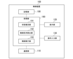
- FIG. 2 is a diagram illustrating an example of the configuration of a control device according to the first embodiment.
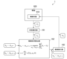
- FIG. 2 is a diagram illustrating an example of data input and output in the system according to the first embodiment.
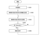
- 5 is a diagram illustrating an example of a procedure of a process performed by a control device according to the first embodiment.
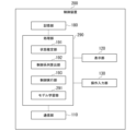
- FIG. FIG. 11 is a diagram illustrating an example of the configuration of a control device according to a second embodiment.
- FIG. 13 is a diagram illustrating an example of the configuration of a control device according to a third embodiment.
- FIG. 13 is a diagram showing an example of a processing procedure in a control method according to the fourth embodiment.
- FIG. 1 is a schematic block diagram illustrating a configuration of a computer according to at least one embodiment.
- letters with a tilde may be represented by adding ⁇ next to the letter.
- an s with a tilde may also be written as s ⁇ .
- Letters with an overline or a macron may be represented by adding ⁇ next to the letter.
- an s with an overline or a macron may also be written as s ⁇ .
- Letters with a circumflex may be represented by adding ⁇ next to the letter.
- an f with a circumflex may also be written as f ⁇ .
- First Embodiment Fig. 1 is a diagram showing an example of the configuration of a system according to the first embodiment.
- the system 1 includes a control device 100 and a controlled object 910.
- the controlled object 910 is not limited to a specific object, but can be any of a variety of controllable objects.
- the controlled object 910 may be equipment such as a plant or factory or a power plant, a system such as a manufacturing line in a factory, or a stand-alone device.
- the controlled object may be a moving object such as an automobile, an airplane, a ship, or a self-propelled mobile robot.
- the operating environment of the control object 910 including the control object 910, is also referred to as the environment 920.
- the state of the environment 920 is also referred to as the state regarding the control object 910, or simply as the state.
- Sensor measurements from sensors installed in the environment 920 are an example of data indicative of the condition being observed.
- a state will be represented by a value.
- a value that represents a state will also be referred to as a state quantity.
- a state here may be a combination of multiple elements, and a state quantity may be represented by a vector. Either a combination of state elements or an element of a state may be referred to as a state.
- the state and state quantity are not limited to specific ones.
- the state may be a state quantity represented by a real value, such as the room temperature of the room in which the control object 910 is set.
- the state may be a state quantity represented by a binary value, such as the opening and closing of an on-off valve provided in the control object 910.
- the control device 100 controls the control object 910.
- the control device 100 calculates a control command value for the control object 910 based on an estimate of states including not only observed states but also non-observed states, and controls the control object 910 using the calculated control command value.
- the control device 100 is expected to be able to calculate the control command value with a relatively high degree of accuracy.
- the control device 100 also calculates a time series of estimated state values when the controlled object 910 is controlled based on the time series of provisionally set control command values from the state indicated by the estimated state values. The control device 100 then searches for a time series of control command values that brings the time series of estimated state values as close as possible to the time series of a preset target state.
- the control device 100 can estimate and evaluate future states with a higher degree of accuracy by estimating and evaluating the time series of states. Furthermore, the control device 100 can estimate and evaluate future states with an even higher degree of accuracy by estimating and evaluating the time series of states that are not being observed.
- the control device 100 may use a model indicating the gradient of time-dependent change in the state to calculate a time series of estimated values of the state and search for a time series of control command values. This allows the control device 100 to use a gradient method such as backpropagation to search for a time series of control command values, and in this respect, the time series of control command values can be efficiently searched.
- the control device 100 may be configured using a computer such as a personal computer (PC) or a workstation (WS).
- FIG. 2 is a diagram showing an example of the configuration of the control device 100.
- the control device 100 includes a communication unit 110, a display unit 120, an operation input unit 130, a storage unit 180, and a processing unit 190.
- the processing unit 190 includes a state estimation unit 191, a control sequence calculation unit 192, and a control execution unit 193.
- the communication unit 110 communicates with other devices.
- the communication unit 110 may transmit control command values for the control target 910 and may receive sensor measurement values from a sensor installed in the environment 920.
- the display unit 120 has a display screen, such as a liquid crystal panel or an LED (Light Emitting Diode) panel, and displays various images.
- the display unit 120 may display various data or parts thereof relating to the control of the control object 910, such as sensor measurement values from a sensor provided in the environment 920, data indicating a state that is not being observed and estimated by the control device 100, and control command values for the control object 910.
- the operation input unit 130 includes input devices such as a keyboard and a mouse, and accepts user operations.
- the operation input unit 130 may accept user operations for setting values of hyperparameters in the control performed by the control device 100, such as the time width of a time series of control command values.
- the storage unit 180 stores various data.
- the storage unit 180 may store a model for calculating a time series of estimated state values.
- the storage unit 180 may also store a time series of a predetermined target state and initial values of a time series of control command values used to search for control command values.
- the storage unit 180 is configured using a storage device provided in the control device 100.
- the processing unit 190 controls each part of the control device 100 to perform various processes.
- the functions of the processing unit 190 are performed, for example, by a CPU (Central Processing Unit) provided in the control device 100 reading and executing a program from the storage unit 180.
- a CPU Central Processing Unit
- the state estimation unit 191 receives input of data indicating states that are targets of observation among states related to the control target 910, and estimates states including states that are not targets of observation. For example, the state estimation unit 191 may perform state estimation using a model of the control object 910, in which the state estimation unit 191 receives a control command value for the control object 910 and a state that is not the object of observation, and outputs an estimate of the state that is the object of observation.
- the state estimation unit 191 also inputs the control command value to be sent to the control object 910 into the model, and also inputs a tentative estimate of the state that is not the object of observation into the model, thereby calculating an estimate of the state that is the object of observation (obtained as the output value of the model). Then, the state estimation unit 191 adjusts the (tentative) estimated value of the unobserved state so that the estimated value of the observed state output by the model comes as close as possible to the actual measured value of the observed state. If it is possible to calculate the gradient of the change in the model output (e.g., the derivative of the model output), the state estimation unit 191 may use a gradient method such as backpropagation to adjust a (tentative) estimate of the unobserved state.
- a gradient method such as backpropagation
- the model used by the state estimation unit 191 is not limited to a specific one.
- the learning method of the model used by the state estimation unit 191 is not limited to a specific method.
- the state estimation unit 191 may use a model obtained by supervised learning, or may use a model obtained by reinforcement learning. Alternatively, the state estimation unit 191 may use the same model as the model used by the control device 100 to obtain a time series of estimated values of the state.
- the control series calculation unit 192 calculates a time series of control for the control object 910 such that the time series of estimated values of the state, which has an initial state including a state that is not the object of observation estimated by the state estimation unit 191, comes closer to the time series of the target state.
- the control sequence calculation unit 192 provisionally sets a time sequence of control command values for the control target 910. This time sequence is also referred to as an initial value of the time sequence of control command values.
- control series calculation unit 192 calculates a time series of estimated values of the state when the control object 910 operates according to the time series of the set control command values, using the state estimated by the state estimation unit 191, including the state that is not the object of observation, as the initial state.
- the control object 910 updates the time series of the control command values so that the time series of the estimated values of the state approaches the time series of the target state as closely as possible.
- the control series calculation unit 192 repeatedly calculates the time series of the estimated state values and updates the time series of the control command values to search for a time series of the control command values that minimizes the difference between the time series of the estimated state values and the time series of the target state.
- the control execution unit 193 controls the control object 910 based on the time series of control command values calculated by the control sequence calculation unit 192. For example, the control execution unit 193 controls the control object 910 by transmitting the first control command value (the control command value at the current time) of the time series of control command values calculated by the control sequence calculation unit 192 to the control object 910 via the communication unit 110.
- FIG. 3 is a diagram showing an example of data input/output in the system 1. As shown in FIG. In the following, time is represented by time steps, and the current time (the time step at which the control device 100 next transmits a control command value for the controlled object 910) is represented as time t0 .
- the state estimation unit 191 acquires an observation value s * t0 of a state that is an observation target among states s t0 at time t 0. Then, the state estimation unit 191 calculates an estimated value s ⁇ t0 of the state at time t 0 and outputs it to the control sequence calculation unit 192.
- the actual measured value of the state may be used as the value of the state to be observed, or a calculated value such as an output value of a model may be used.
- the control sequence calculation unit 192 acquires the state estimate s ⁇ t0 at time t0 calculated by the state estimation unit 191, the time series s ⁇ t0 , ..., ⁇ t0+T of the target state, and initial values a ⁇ t0 , ..., a ⁇ t0+T-1 of the time series of control command values for the control object 910.
- control sequence calculation unit 192 solves an optimization problem that brings the time series s ⁇ t0 , ..., s ⁇ t0+T of the state estimate as close as possible to the time series s ⁇ t0 , ..., ⁇ t0+T of the target state, and searches for the time series a t0 , ..., a t0+T-1 of the control command values.
- T is an integer constant that is predetermined as a time width in the time series of the control command values calculated by the control sequence calculation unit 192 .
- the time series s t0 , . . . , s t0+T of the target states and the initial values a t0 , . . . , a t0+T ⁇ 1 of the time series may be predetermined by, for example, a user.
- the control sequence calculation unit 192 may search for a time sequence of the control command value based on the equation (1).
- Equation (1) represents a search for a time series a t0 , ... , a t0+T-1 of control command values such that the sum of the magnitudes of the differences between the state estimates s ⁇ t and the target state s t from time t 0 to t 0 +T is as small as possible.
- the index of the closeness between the state estimates s t and the target state s t is not limited to a specific one.
- the control sequence calculation unit 192 may use the square error (s t - s t ) 2 between the state estimates s t and the target state s t as the index of the closeness between the state estimates s t and the target state s t .
- the control sequence calculation unit 192 may integrate the time derivative ds t /dt of the state estimate s t , thereby calculating a time series s t0 , ..., s t0 + T of the state estimate based on the state estimate s t0 at time t0.
- the control sequence calculation unit 192 may calculate the time derivative ds t / dt of the state estimate s t by using neural ordinary differential equations (Neural ODE).
- the neural ordinary differential equation is a calculation model that represents an ordinary differential equation in a neural network. The calculation of ds t / dt by the neural ordinary differential equation is expressed as in Equation (2).
- f ⁇ is a function representing a neural ordinary differential equation.
- the neural ordinary differential equation receives state estimates s ⁇ t and control command values a t as inputs, and outputs time derivatives ⁇ t /dt of the state estimates s ⁇ t .
- ⁇ represents an internal variable of the neural ordinary differential equation. The value of ⁇ is updated by learning the neural ordinary differential equation.
- Equation (3) the integral of the time derivative f ⁇ (s ⁇ ( ⁇ ), at ; ⁇ ) of the state estimate shown in the neural ordinary differential equation is expressed as shown in Equation (3).
- the control sequence calculation unit 192 can calculate the estimated value s ⁇ t+1 of the next state s t+1 for the estimated value s ⁇ t of the state s t based on equation (3).
- the derivative may be approximately expressed using a difference.
- the control sequence calculation unit 192 may use a numerical integration method to calculate the integral.
- ⁇ t t0 t0+T
- can be regarded as an example of an evaluation function in which the smaller the function value, the better the evaluation.
- the evaluation function used by the control sequence calculation unit 192 to evaluate the time series of the estimated value of the state is not limited to a specific one.
- the control sequence calculation unit 192 may search for the time series of the control command value based on the formula (4) instead of the formula (1).
- l(s t , a t ) is a function indicating an evaluation when the controlled object operates according to a control command value a t under a state s t .
- a cost function is used as the function l, in which the smaller the function value, the better the evaluation.
- the control sequence calculation unit 192 outputs the calculated time sequence of control command values a t0 , ..., a t0+T-1 to the control execution unit 193. Alternatively, the control sequence calculation unit 192 may output only the control command value a t0 at time t to the control execution unit 193.
- the control execution unit 193 controls the control target 910 based on the control command value calculated by the control sequence calculation unit 192. Specifically, the control execution unit 193 transmits a control command value a t0 at time t to the control target 910 via the communication unit 110.
- FIG. 4 is a diagram showing an example of a procedure of processing performed by the control device 100.
- the state estimation unit 191 receives an input of an observation value s * t0 of a state that is an observation target among states related to the control object 910, and calculates an estimation value s ⁇ t0 of a state including a state that is not an observation target (step S101).
- control series calculation unit 192 sets initial values of the time series a t0 , ..., a t0+T-1 of the control command values for the control target 910 (step S102). For example, the control series calculation unit 192 may acquire the time series of control command values planned in advance by the user as the initial values a t0 , ..., a t0+T-1 of the time series of control command values, and set the initial values a t0 , ..., a t0+T-1 of the time series of control command values.
- control series calculation unit 192 searches for a time series a t0 , ..., a t0+T-1 of control command values such that the time series s ⁇ t0 , ..., s ⁇ t0+T of the estimated values of the state is as close as possible to the time series s --t0 , ..., s --t0+T of the target state (step S103).
- control sequence calculation unit 192 updates the time series a t0 , ..., a t0+T- 1 of the control command values so that the time series s ⁇ t0 , ..., s ⁇ t0+T of the state estimates approaches the time series s _t0 , ..., s _t0+T of the target state.
- control sequence calculation unit 192 may select the time series a t0 , ..., a t0+T-1 of the control command values such that the time series s ⁇ t0 , ..., s ⁇ t0 +T of the state estimates deviates from the time series s _t0 , ..., s _t0 +T of the target state.
- the control sequence calculation unit 192 determines whether or not a termination condition for the search of the time sequence of the control command value is satisfied (step S104).
- the termination condition here is not limited to a specific one.
- the termination condition in step S104 may be a condition that the loop from step S103 to S104 has been executed a predetermined number of times or more.
- step S104 determines that the termination condition is satisfied in step S104 (step S104: YES)
- the control execution unit 193 executes control of the control object 910 (step S105). Specifically, the control execution unit 193 transmits the control command value a t0 at the time t0 calculated by the control sequence calculation unit 192 to the control object 910 via the communication unit 110.
- step S105 the process returns to step S101, at which point the time step advances by one step.
- the control device 100 repeats the loop of steps S101 to S105 until the control of the control target 910 is completed.
- the state estimation unit 191 receives input of data indicating states related to the control object 910 that are subject to observation, and estimates states including states that are not subject to observation.
- the control series calculation unit 192 calculates a time series of control command values for the control object 910 that improves the evaluation of the time series of estimated values of states in which the initial state is a state that includes a state that is not subject to observation.
- the control execution unit 193 performs control of the control object 910 based on the obtained time series of control command values.
- the control device 100 is expected to be able to calculate the control command value with a relatively high degree of accuracy in that the control command value for the control object 910 is calculated based on not only the observed state but also the non-observed state through control using a model that indicates the relationship between the control command value for the control object 910 and the state related to the control object 910.
- control series calculation unit 192 calculates a time series of control command values for the control object 910 such that the time series of estimated values of a state, which has an initial state including a state that is not the object of observation, comes closer to the time series of the target state.
- the control device 100 when a time series of a target state is determined, such as when a user creates a control plan for the control object 910, the control object 910 can be controlled according to the time series of the target state.
- the control series calculation unit 192 also uses a gradient model to calculate a time series of control command values for the control object 910.
- the gradient model is a model that indicates the relationship between the state of the control object 910, the control command values for the control object 910, and the change over time of the state of the control object 910.
- the control device 100 can use a gradient method such as backpropagation to search for a time series of control command values for the control object 910. In this respect, the control device 100 can efficiently search for a time series of control command values for the control object 910.
- Second Embodiment Fig. 5 is a diagram showing an example of the configuration of a control device according to the second embodiment.
- the control device 200 includes a communication unit 110, a display unit 120, an operation input unit 130, a storage unit 180, and a processing unit 290.
- the processing unit 290 includes a state estimation unit 191, a control sequence calculation unit 192, a control execution unit 193, and a model learning unit 291.
- the control device 200 differs from the control device 100 in that the processing unit 290 further includes a model learning unit 291 in addition to the units included in the processing unit 190 of the control device 100. In other respects, the control device 200 is similar to the control device 100.
- the configuration of the system in the second embodiment is similar to that in the first embodiment. In the second embodiment, the control device 100 in FIG.
- the model learning unit 291 uses data obtained by simulating the control object 910 to learn a model indicating the relationship between the state of the control object 910, the control command value for the control object 910, and the time change of the state of the control object 910.
- the model learning unit 291 corresponds to an example of a model learning means.
- the control sequence calculation unit 192 calculates a time sequence of control command values for the control target 910 using the learned model.
- a model showing the relationship between the state of the controlled object 910, the control command value for the controlled object 910, and the change over time of the state of the controlled object 910 is also called a gradient model.
- the control device 200 uses a neural ordinary differential equation as a gradient model will be described as an example.
- the gradient model used by the control device 200 is not limited to a specific type of model, and may be any of various models that indicate the gradient of the time change of the state of the control target 910.
- the model learning unit 291 acquires training data that is a combination of estimated values s ⁇ t of a state for the control object 910, a control command value a t for the control object 910, and estimated values s ⁇ t+1 of a next state for the control object 910.
- the estimated values s ⁇ t+1 of the next state for the control object 910 are estimated values of a state (next state) s t + 1 to which the control object 910 transitions from state s t when the control object 910 operates in accordance with a control command value a t under state s t indicated by the estimated values s ⁇ t .
- the model learning unit 291 inputs the state estimates s ⁇ t and the control command value a t for the control object 910 into the neural ordinary differential equation to calculate a time derivative ds ⁇ t /dt of the state estimates s ⁇ t .
- the model learning unit 291 updates the values of the internal variables of the neural ordinary differential equation so that the next state estimates s ⁇ t+1 calculated by integrating ds ⁇ t /dt approaches the next state estimates s ⁇ t+1 indicated in the training data.
- the model learning unit 291 may use a gradient method such as backpropagation to learn neural ordinary differential equations.
- the model learning unit 291 learns the gradient model using data obtained from a simulation of the control object 910.
- the gradient model is a model that shows the relationship between the state of the control object 910, the control command value for the control object 910, and the change over time in the state of the control object 910.
- a model showing the gradient of time change of the state (estimated value of the state) can be obtained, and the control series calculation unit 192 can use a gradient method such as backpropagation when searching for the time series a t0 , ..., a t0+T-1 of the control command values for the control object 910.
- the time series a t0 , ..., a t0+T-1 of the control command values for the control object 910 can be efficiently calculated.
- a model that can be used for gradient methods such as backpropagation can be obtained by learning using data obtained by simulating the control target 910 as training data.
- the cost of constructing a model is relatively low.
- Fig. 6 is a diagram showing an example of the configuration of a control device according to the third embodiment.
- a control device 610 includes a state estimation unit 611, a control sequence calculation unit 612, and a control execution unit 613.
- the state estimation unit 611 receives data indicating states of the control object that are subject to observation, and estimates states including states that are not subject to observation.
- the control series calculation unit 612 calculates a time series of control command values for the control object that improves evaluation of a time series of estimated values of states in which a state including a state that is not subject to observation is an initial state.
- the control execution unit 613 performs control of the control object based on the obtained time series of control command values.
- the state estimation unit 611 corresponds to an example of a state estimation means
- the control sequence calculation unit 612 corresponds to an example of a control sequence calculation means
- the control execution unit 613 corresponds to an example of a control execution means.
- the control device 610 is expected to be able to calculate the control command value with a relatively high degree of accuracy in that the control command value for the control object is calculated based on not only the observed state but also the unobserved state through control using a model that indicates the relationship between the control command value for the control object and the state of the control object.
- the state estimation unit 611 can be realized, for example, by using the functions of the state estimation unit 191 shown in FIG. 1, etc.
- the control sequence calculation unit 612 can be realized, for example, by using the functions of the control sequence calculation unit 192 shown in FIG. 1, etc.
- the control execution unit 613 can be realized, for example, by using the functions of the control execution unit 193 shown in FIG. 1, etc.
- Fig. 7 is a diagram showing an example of a procedure of a process in a control method according to the fourth embodiment.
- the control method shown in Fig. 7 includes estimating a state (step S611), calculating a control sequence (step S612), and executing control (step S613).
- step S611 the computer receives input of data indicating states related to the controlled object that are subject to observation, and estimates states including states that are not subject to observation.
- step S612 the computer calculates a time series of control for the control object that improves the evaluation of the time series of estimated values of states whose initial states include states that are not observed.
- step S613 the computer performs control on the control target based on the obtained control time series.
- the control method shown in Figure 7 is expected to be able to calculate control command values with a relatively high degree of accuracy, since the control method uses a model that indicates the relationship between the control command value for the controlled object and the state of the controlled object, and calculates the control command value for the controlled object based on not only the observed state but also the unobserved state.
- FIG. 8 is a schematic block diagram illustrating a computer configuration according to at least one embodiment.
- a computer 700 includes a CPU 710 , a main memory device 720 , an auxiliary memory device 730 , an interface 740 , and a non-volatile recording medium 750 .
- any one or more of the above-mentioned control devices 100, 200, and 610, or parts thereof, may be implemented in the computer 700.
- the operation of each of the above-mentioned processing units is stored in the auxiliary storage device 730 in the form of a program.
- the CPU 710 reads the program from the auxiliary storage device 730, expands it in the main storage device 720, and executes the above-mentioned processing in accordance with the program.
- the CPU 710 also secures memory areas in the main storage device 720 corresponding to each of the above-mentioned memory units in accordance with the program. Communication between each device and other devices is executed by the interface 740 having a communication function and communicating according to the control of the CPU 710.
- the operations of the processing unit 190 and each of its units are stored in the auxiliary storage device 730 in the form of a program.
- the CPU 710 reads the program from the auxiliary storage device 730, expands it in the main storage device 720, and executes the above-mentioned processing according to the program.
- the CPU 710 also reserves a memory area for the memory unit 180 in the main memory device 720 in accordance with the program. Communication with other devices by the communication unit 110 is achieved by the interface 740 having a communication function and operating under the control of the CPU 710. Display of various images by the display unit 120 is achieved by the interface 740 having a display device and displaying various images under the control of the CPU 710. Reception of user operations by the operation input unit 130 is achieved by the interface 740 having an input device and accepting user operations under the control of the CPU 710.
- the operation of the processing unit 290 and each of its units is stored in the auxiliary storage device 730 in the form of a program.
- the CPU 710 reads the program from the auxiliary storage device 730, expands it in the main storage device 720, and executes the above-mentioned processing according to the program.
- the CPU 710 also reserves a memory area for the memory unit 180 in the main memory device 720 in accordance with the program. Communication with other devices by the communication unit 110 is achieved by the interface 740 having a communication function and operating under the control of the CPU 710. Display of various images by the display unit 120 is achieved by the interface 740 having a display device and displaying various images under the control of the CPU 710. Reception of user operations by the operation input unit 130 is achieved by the interface 740 having an input device and accepting user operations under the control of the CPU 710.
- the operations of the state estimation unit 611, the control sequence calculation unit 612, and the control execution unit 613 are stored in the auxiliary storage device 730 in the form of a program.
- the CPU 710 reads the program from the auxiliary storage device 730, expands it in the main storage device 720, and executes the above-mentioned processing according to the program.
- the CPU 710 also allocates a storage area in the main memory device 720 for the control device 610 to perform processing according to the program. Communication between the control device 610 and other devices is performed by the interface 740, which has a communication function and operates according to the control of the CPU 710. Interaction between the control device 610 and the user is performed by the interface 740, which has a display device and an input device, displaying various images according to the control of the CPU 710, and accepting user operations.
- any one or more of the above-mentioned programs may be recorded on the non-volatile recording medium 750.
- the interface 740 may read the program from the non-volatile recording medium 750.
- the CPU 710 may then directly execute the program read by the interface 740, or may temporarily store the program in the main memory device 720 or the auxiliary memory device 730 and then execute it.
- a program for executing all or part of the processing performed by the control devices 100, 200, and 610 may be recorded on a computer-readable recording medium, and the program recorded on the recording medium may be read into a computer system and executed to perform processing of each part.
- the term "computer system” here includes hardware such as the OS and peripheral devices.
- the term "computer-readable recording medium” refers to portable media such as flexible disks, optical magnetic disks, ROMs (Read Only Memory), and CD-ROMs (Compact Disc Read Only Memory), as well as storage devices such as hard disks built into computer systems.
- the above-mentioned program may be for realizing part of the above-mentioned functions, or may be capable of realizing the above-mentioned functions in combination with a program already recorded in the computer system.
- the present invention may be applied to a control device, a control method, and a recording medium.
Landscapes
- Physics & Mathematics (AREA)
- General Physics & Mathematics (AREA)
- Engineering & Computer Science (AREA)
- Automation & Control Theory (AREA)
- Feedback Control In General (AREA)
Abstract
Description
以下では、チルダ(Tilde)を付された文字を、その文字の次に~を付すことで表す場合がある。例えば、チルダを付されたsを、s~とも表記する。また、オーバーライン(Overline)またはマクロン(Macron)を付された文字を、その文字の次に ̄を付すことで表す場合がある。例えば、オーバーラインまたはマクロンを付されたsを、s ̄とも表記する。また、サーカムフレックス(Circumflex)を付された文字を、その文字の次に^を付すことで表す場合がある。例えば、サーカムフレックスを付されたfを、f^とも表記する。
図1は、第一実施形態に係るシステムの構成の例を示す図である。図1に示す構成で、システム1は、制御装置100と、制御対象910とを備える。
環境920に設けられたセンサによるセンサ測定値は、観測対象となっている状態を示すデータの例に該当する。
これにより、制御装置100は、制御指令値の時系列の探索に、バックプロパゲーション(Backpropagation、誤差逆伝播法)等の勾配法を用いることができ、この点で、制御指令値の時系列を効率的に探索することができる。
制御装置100は、例えばパソコン(Personal Computer;PC)またはワークステーション(Workstation1;WS)等のコンピュータを用いて構成されていてもよい。
例えば、状態推定部191が、制御対象910に対する制御指令値と、観測対象となっていない状態との入力を受けて、観測対象となっている状態の推定値を出力する、制御対象910のモデルを用いて状態推定を行うようにしてもよい。
そして、状態推定部191は、モデルが出力する、観測対象となっている状態の推定値を、観測対象となっている状態の実測値になるべく近づけるように、観測対象となっていない状態の(仮の)推定値を調整する。
モデルの出力の変化の勾配(例えば、モデルの出力の微分)を算出可能な場合、状態推定部191が、バックプロパゲーション等の勾配法を用いて、観測対象となっていない状態の(仮の)推定値を調整するようにしてもよい。
具体的には、制御系列算出部192は、制御対象910に対する制御指令値の時系列を仮に設定する。この時系列を、制御指令値の時系列の初期値とも称する。
以下では、時刻をタイムステップで表し、現在の時刻(次に、制御装置100が制御対象910に対する制御指令値を送信するタイムステップ)を時刻t0で表すものとする。
状態推定部191が、制御系列算出部192へ出力する状態の推定値s~ t0のうち、観測対象となっている状態の値として、状態の実測値を用いるようにしてもよいし、モデルの出力値など計算値を用いるようにしてもよい。
目標状態の時系列s ̄t0,・・・,s ̄t0+Tと、時系列の初期値a ̄t0,・・・,a ̄t0+T-1とは、例えば、ユーザによって予め定められていてもよい。
制御系列算出部192が、式(1)に基づいて、制御指令値の時系列を探索するようにしてもよい。


θは、ニューラル常微分方程式の内部変数を表す。θの値は、ニューラル常微分方程式の学習によって更新される。

ただし、制御系列算出部192が、状態の推定値の時系列の評価に用いる評価関数は、特定のものに限定されない。例えば、制御系列算出部192が、式(1)に代えて、式(4)に基づいて、制御指令値の時系列の探索を行うようにしてもよい。

図4の処理で、状態推定部191は、制御対象910に関する状態のうち観測対象となっている状態の観測値s* t0の入力を受けて、観測対象となっていない状態を含む状態の推定値s~ t0を算出する(ステップS101)。
終了条件が成立していないと制御系列算出部192が判定した場合(ステップS104:NO)、処理がステップS103へ戻る。
制御装置100は、制御対象910に対する制御を終了するまで、ステップS101からS105のループを繰り返す。
制御装置100によれば、ユーザが制御対象910に対する制御計画を作成している場合など、目標状態の時系列が定められている場合に、目標状態の時系列に従って制御対象910を制御することができる。
図5は、第2実施形態に係る制御装置の構成の例を示す図である。図2に示す構成で、制御装置200は、通信部110と、表示部120と、操作入力部130と、記憶部180と、処理部290とを備える。処理部290は、状態推定部191と、制御系列算出部192と、制御実行部193と、モデル学習部291とを備える。
制御装置200では、処理部290が、制御装置100の処理部190が備える各部に加えてさらに、モデル学習部291を備える点で、制御装置100と異なる。それ以外の点では、制御装置200は、制御装置100と同様である。
第二実施形態におけるシステムの構成は、第一実施形態の場合と同様である。第二実施形態では、図1の制御装置100を制御装置200と読み替えることとする。
制御系列算出部192は、学習済みのモデルを用いて、制御対象910に対する制御指令値の時系列を算出する。
以下では、制御装置200が、勾配モデルとしてニューラル常微分方程式を用いる場合を例に説明する。ただし、制御装置200が用いる勾配モデルは、特定の種類のモデルに限定されず、制御対象910に関する状態の時間変化の勾配を示すいろいろなモデルとすることができる。
モデル学習部291が、バックプロパゲーション等の勾配法を用いて、ニューラル常微分方程式の学習を行うようにしてもよい。
図6は、第三実施形態に係る制御装置の構成の例を示す図である。図6に示す構成で、制御装置610は、状態推定部611と、制御系列算出部612と、制御実行部613とを備える。
状態推定部611は、状態推定手段の例に該当する。制御系列算出部612は、制御系列算出手段の例に該当する。制御実行部613は、制御実行手段の例に該当する。
図7は、第四実施形態に係る制御方法における処理の手順の例を示す図である。図7に示す制御方法は、状態を推定すること(ステップS611)と、制御系列を算出すること(ステップS612)と、制御を実行すること(ステップS613)とを含む。
制御系列を算出すること(ステップS612)では、コンピュータが、観測対象となっていない状態を含む状態を初期状態とする状態の推定値の時系列に対する評価がより良くなるような、制御対象に対する制御の時系列を算出する。
制御を実行すること(ステップS613)では、コンピュータが、得られた制御の時系列に基づいて、制御対象に対する制御を行う。
図8に示す構成で、コンピュータ700は、CPU710と、主記憶装置720と、補助記憶装置730と、インタフェース740と、不揮発性記録媒体750とを備える。
また、「コンピュータ読み取り可能な記録媒体」とは、フレキシブルディスク、光磁気ディスク、ROM(Read Only Memory)、CD-ROM(Compact Disc Read Only Memory)等の可搬媒体、コンピュータシステムに内蔵されるハードディスク等の記憶装置のことをいう。また上記プログラムは、前述した機能の一部を実現するためのものであってもよく、さらに前述した機能をコンピュータシステムにすでに記録されているプログラムとの組み合わせで実現できるものであってもよい。
100、200、610 制御装置
110 通信部
120 表示部
130 操作入力部
180 記憶部
190、290 処理部
191、611 状態推定部
192、612 制御系列算出部
193、613 制御実行部
291 モデル学習部
910 制御対象
920 環境
Claims (6)
- 制御対象に関する状態のうち観測対象となっている状態を示すデータの入力を受けて、観測対象となっていない状態を含む状態を推定する状態推定手段と、
前記観測対象となっていない状態を含む状態を初期状態とする状態の推定値の時系列に対する評価がより良くなるような、前記制御対象に対する制御指令値の時系列を算出する制御系列算出手段と、
得られた制御指令値の時系列に基づいて、前記制御対象に対する制御を行う制御実行手段と、
を備える制御装置。 - 前記制御系列算出手段は、前記観測対象となっていない状態を含む状態を初期状態とする状態の推定値の時系列が、目標状態の時系列により近付くような、前記制御対象に対する制御指令値の時系列を算出する、
請求項1に記載の制御装置。 - 前記制御系列算出手段は、前記制御対象に関する状態と、前記制御対象に対する制御指令値と、前記制御対象に関する状態の時間変化との関係を示すモデルを用いて、前記制御指令値の時系列を算出する、
請求項1または請求項2に記載の制御装置。 - 前記制御対象のシミュレーションにて得られたデータを用いて、前記制御対象に関する状態と、前記制御対象に対する制御指令値と、前記制御対象に関する状態の時間変化との関係を示すモデルの学習を行うモデル学習手段
を更に備える
請求項3に記載の制御装置。 - コンピュータが、
制御対象に関する状態のうち観測対象となっている状態を示すデータの入力を受けて、観測対象となっていない状態を含む状態を推定し、
前記観測対象となっていない状態を含む状態を初期状態とする状態の推定値の時系列に対する評価がより良くなるような、前記制御対象に対する制御の時系列を算出し、
得られた制御の時系列に基づいて、前記制御対象に対する制御を行う、
ことを含む制御方法。 - コンピュータに、
制御対象に関する状態のうち観測対象となっている状態を示すデータの入力を受けて、観測対象となっていない状態を含む状態を推定することと、
前記観測対象となっていない状態を含む状態を初期状態とする状態の推定値の時系列に対する評価がより良くなるような、前記制御対象に対する制御の時系列を算出することと、
得られた制御の時系列に基づいて、前記制御対象に対する制御を行うことと、
を実行させるためのプログラムを記録している記録媒体。
Priority Applications (2)
| Application Number | Priority Date | Filing Date | Title |
|---|---|---|---|
| PCT/JP2023/012662 WO2024201751A1 (ja) | 2023-03-28 | 2023-03-28 | 制御装置、制御方法および記録媒体 |
| JP2025509369A JPWO2024201751A5 (ja) | 2023-03-28 | 制御装置、制御方法およびプログラム |
Applications Claiming Priority (1)
| Application Number | Priority Date | Filing Date | Title |
|---|---|---|---|
| PCT/JP2023/012662 WO2024201751A1 (ja) | 2023-03-28 | 2023-03-28 | 制御装置、制御方法および記録媒体 |
Publications (1)
| Publication Number | Publication Date |
|---|---|
| WO2024201751A1 true WO2024201751A1 (ja) | 2024-10-03 |
Family
ID=92903579
Family Applications (1)
| Application Number | Title | Priority Date | Filing Date |
|---|---|---|---|
| PCT/JP2023/012662 Ceased WO2024201751A1 (ja) | 2023-03-28 | 2023-03-28 | 制御装置、制御方法および記録媒体 |
Country Status (1)
| Country | Link |
|---|---|
| WO (1) | WO2024201751A1 (ja) |
Citations (3)
| Publication number | Priority date | Publication date | Assignee | Title |
|---|---|---|---|---|
| JP2020082332A (ja) * | 2018-11-30 | 2020-06-04 | オムロン株式会社 | 制御装置、制御方法、及び制御プログラム |
| WO2021084587A1 (ja) * | 2019-10-28 | 2021-05-06 | 株式会社安川電機 | 機械学習データ生成装置、機械学習装置、作業システム、コンピュータプログラム、機械学習データ生成方法及び作業機械の製造方法 |
| JP2021091079A (ja) * | 2019-12-10 | 2021-06-17 | 富士フイルム株式会社 | ロボットの制御装置、制御方法、及びプログラム |
-
2023
- 2023-03-28 WO PCT/JP2023/012662 patent/WO2024201751A1/ja not_active Ceased
Patent Citations (3)
| Publication number | Priority date | Publication date | Assignee | Title |
|---|---|---|---|---|
| JP2020082332A (ja) * | 2018-11-30 | 2020-06-04 | オムロン株式会社 | 制御装置、制御方法、及び制御プログラム |
| WO2021084587A1 (ja) * | 2019-10-28 | 2021-05-06 | 株式会社安川電機 | 機械学習データ生成装置、機械学習装置、作業システム、コンピュータプログラム、機械学習データ生成方法及び作業機械の製造方法 |
| JP2021091079A (ja) * | 2019-12-10 | 2021-06-17 | 富士フイルム株式会社 | ロボットの制御装置、制御方法、及びプログラム |
Also Published As
| Publication number | Publication date |
|---|---|
| JPWO2024201751A1 (ja) | 2024-10-03 |
Similar Documents
| Publication | Publication Date | Title |
|---|---|---|
| KR102596158B1 (ko) | 이중 액터 크리틱 알고리즘을 통한 강화 학습 | |
| Urrea et al. | Design, simulation, comparison and evaluation of parameter identification methods for an industrial robot | |
| Tamar et al. | Learning from the hindsight plan—episodic mpc improvement | |
| US20210178600A1 (en) | System and Method for Robust Optimization for Trajectory-Centric ModelBased Reinforcement Learning | |
| CN118043746A (zh) | 利用仿真失败校准工业系统模型的校准系统和方法 | |
| CN113554680B (zh) | 目标跟踪方法、装置、无人机和存储介质 | |
| McMahon et al. | A survey on the integration of machine learning with sampling-based motion planning | |
| JP7552714B2 (ja) | 情報処理装置、情報処理方法およびプログラム | |
| Suryan et al. | Multifidelity reinforcement learning with gaussian processes: model-based and model-free algorithms | |
| US20220237349A1 (en) | Model generation device, system, parameter calculation device, model generation method, parameter calculation method, and recording medium | |
| JP2025009891A (ja) | デジタルツインを使用してシステムを制御するためのデバイスおよび方法 | |
| JP5220542B2 (ja) | 制御器、制御方法及び制御プログラム | |
| US20240198518A1 (en) | Device and method for controlling a robot | |
| Varvia et al. | mgpr: An R package for multivariate Gaussian process regression | |
| Du et al. | Reinforcement learning | |
| WO2024201751A1 (ja) | 制御装置、制御方法および記録媒体 | |
| CN110879530A (zh) | 用于对动态模型进行安全的训练的方法 | |
| US20250165679A1 (en) | State Estimation using Physics-Constrained Machine Learning | |
| US20240393751A1 (en) | Systems and methods for controlling an underactuated mechanical system with multiple degrees of freedom | |
| Zhu et al. | Robotic visual-inertial calibration via deep deterministic policy gradient learning | |
| JP2024140139A (ja) | 学習装置、学習方法およびプログラム | |
| Duan et al. | Hand-in-Hand guidance: an explore-exploit based reinforcement learning method for performance driven assembly-adjustment | |
| Zhu et al. | Visual inertial calibration of mobile robotic system based on reinforcement learning | |
| JP7586302B2 (ja) | 推定装置、推定方法およびプログラム | |
| CN114761966B (zh) | 用于以轨迹为中心的基于模型的强化学习的稳健优化的系统及方法 |
Legal Events
| Date | Code | Title | Description |
|---|---|---|---|
| 121 | Ep: the epo has been informed by wipo that ep was designated in this application |
Ref document number: 23930391 Country of ref document: EP Kind code of ref document: A1 |
|
| ENP | Entry into the national phase |
Ref document number: 2025509369 Country of ref document: JP Kind code of ref document: A |
|
| WWE | Wipo information: entry into national phase |
Ref document number: 2025509369 Country of ref document: JP |
|
| NENP | Non-entry into the national phase |
Ref country code: DE |
|
| 122 | Ep: pct application non-entry in european phase |
Ref document number: 23930391 Country of ref document: EP Kind code of ref document: A1 |