WO2024201706A1 - 検知装置、検知方法、及び非一時的なコンピュータ可読媒体 - Google Patents
検知装置、検知方法、及び非一時的なコンピュータ可読媒体 Download PDFInfo
- Publication number
- WO2024201706A1 WO2024201706A1 PCT/JP2023/012482 JP2023012482W WO2024201706A1 WO 2024201706 A1 WO2024201706 A1 WO 2024201706A1 JP 2023012482 W JP2023012482 W JP 2023012482W WO 2024201706 A1 WO2024201706 A1 WO 2024201706A1
- Authority
- WO
- WIPO (PCT)
- Prior art keywords
- shelf
- image
- image area
- item
- model
- Prior art date
- Legal status (The legal status is an assumption and is not a legal conclusion. Google has not performed a legal analysis and makes no representation as to the accuracy of the status listed.)
- Ceased
Links
Images





Classifications
-
- G—PHYSICS
- G06—COMPUTING OR CALCULATING; COUNTING
- G06T—IMAGE DATA PROCESSING OR GENERATION, IN GENERAL
- G06T7/00—Image analysis
- G06T7/10—Segmentation; Edge detection
- G06T7/11—Region-based segmentation
Definitions
- the present disclosure relates to a detection device, a detection method, and a non-transitory computer-readable medium.
- a technology has been proposed that uses a single trained discrimination model to detect areas in an image of a group of items, such as merchandise, where the group of items is present in a continuous manner (for example, Patent Document 1).
- a single classification model may not provide sufficient accuracy in detecting an image region.
- a classification model usually has objects that it is good at detecting and objects that it is not good at detecting. For this reason, the inventor has found that it is possible to improve the accuracy in detecting an image region by applying a first model and a second model with different characteristics to an image of a group of items.
- One of the objectives of the present disclosure is to provide a detection device, a detection method, and a non-transitory computer-readable medium that can improve the detection accuracy of an image region. It should be noted that this objective is only one of multiple objectives that the multiple embodiments disclosed in this specification aim to achieve. Other objectives or problems and novel features will become apparent from the description of this specification or the accompanying drawings.
- the sensing device comprises: A first detection unit that detects an image of a single item in a captured image of the item shelf; a first identification unit that identifies a plurality of shelf level image areas in the captured image, each of which corresponds to a plurality of shelf levels of the item shelf; a determination unit that determines a posture of an article placed on a shelf corresponding to each shelf level image area based on an image of a single article detected in each shelf level image area; a determination unit that determines a model to be used when each shelf image area is set as a processing target image area from among a plurality of models, each model being a model for detecting an article group image area and having different detection characteristics, based on the posture in which the article is placed; a second detection unit that detects an item group image area corresponding to an image of an item group in the processing target image area by applying the usage model to the processing target image area; Equipped with:
- the method of detection comprises: Detecting an image of a single item in a photographed image of the item shelf; Identifying a plurality of shelf level image areas in the captured image, each of which corresponds to a plurality of shelf levels of the item shelf; determining a posture of an article placed on a shelf corresponding to each shelf image area based on an image of the article alone detected in each shelf image area; determining a model to be used when each shelf image area is set as a processing target image area from among a plurality of models each of which is a model for detecting an article group image area and has different detection characteristics based on the posture in which the article is placed; detecting an item group image region in the target image region corresponding to an image of an item group by applying the usage model to the target image region; Includes.
- a non-transitory computer readable medium comprises: Detecting an image of a single item in a photographed image of the item shelf; Identifying a plurality of shelf level image areas in the captured image, each of which corresponds to a plurality of shelf levels of the item shelf; determining a posture of an article placed on a shelf corresponding to each shelf image area based on an image of the article alone detected in each shelf image area; determining a model to be used when each shelf image area is set as a processing target image area from among a plurality of models each of which is a model for detecting an article group image area and has different detection characteristics based on the posture in which the article is placed; detecting an item group image region in the target image region corresponding to an image of an item group by applying the usage model to the target image region;
- the program for causing the detection device to execute the process including the steps described above is stored.
- the present disclosure provides a detection device, a detection method, and a non-transitory computer-readable medium that can improve the accuracy of detecting an image area.
- FIG. 2 is a block diagram showing an example of a detection device according to the first embodiment.
- 4 is a flowchart showing an example of a processing operation of the detection device in the first embodiment.
- FIG. 11 is a block diagram showing an example of a detection device according to a second embodiment.
- FIG. 13 is a diagram showing an example of an item shelf image.
- FIG. 11 is a diagram illustrating an example of a second image area.
- FIG. 4 is a diagram illustrating an example of a first image area.
- FIG. 13 is a block diagram showing an example of a detection device according to a third embodiment.
- FIG. 13 is a diagram illustrating an example of an integrated image.
- FIG. 2 illustrates an example of a hardware configuration of a detection device.
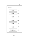
- Fig. 1 is a block diagram showing an example of a detection device in the first embodiment.
- a detection device 10 has a detection unit (first detection unit) 11, an identification unit (first identification unit) 12, a determination unit 13, a detection unit (second detection unit) 14, and a determination unit 15.
- This captured image is, for example, an item shelf image of an item shelf. The following description will be given on the assumption that the captured image is an item shelf image.
- This item shelf has a plurality of shelf levels.
- the detection unit 11 detects an "image of a single item" of a single item in a captured image.
- the detection unit 11 may detect an "image of a single item” by using "AI (Artificial Intelligence)" that detects individual items.
- AI Artificial Intelligence
- the identification unit 12 identifies a number of "shelf level image areas" in the captured image, each of which corresponds to a number of shelf levels.
- a shelf level image area corresponding to one shelf level is, for example, an image area corresponding to the space between the shelf board of that shelf level and the shelf board of the shelf level immediately above that shelf level.
- the determination unit 13 determines the posture in which the item is placed on the shelf corresponding to each shelf image area based on the single item image detected in each shelf image area.
- the postures in which the item is placed on the shelf include, for example, an upright posture (hereinafter sometimes referred to as the "first posture”) and a lying posture (hereinafter sometimes referred to as the "second posture").
- the determination unit 15 determines, from among the multiple models, a "model to be used” when each shelf image area is set as the "image area to be processed” of the detection unit 14, based on the "posture in which the item is placed on the shelf” determined by the determination unit 13.
- Each of the multiple models is a model for detecting the item group image area. Furthermore, the multiple models have different detection characteristics.
- the detection unit 14 detects an "item group image area” that corresponds to an image of an item group in the "processing target image area” by applying the "usage model” to the "processing target image area.”
- the detection unit 14 sets each of the multiple shelf level image areas identified by the identification unit 12 as the "processing target image area.”
- Fig. 2 is a flowchart showing an example of the processing operation of the detection device in the first embodiment.
- the detection unit 11 detects an image of a single item in the captured image (step S101).
- the identification unit 12 identifies a number of shelf level image areas in the captured image that respectively correspond to a number of shelf levels (step S102).
- the determination unit 13 determines the posture in which the item is placed on the shelf corresponding to each shelf image area based on the image of the individual item detected in each shelf image area (step S103).
- the determination unit 15 determines, based on the determined "posture in which the item is placed on the shelf,” from among a number of models, a model to be used when each shelf image area is set as the processing target image area (step S104).
- the detection unit 14 detects an item group image area in the image area to be processed by applying the model used to the image area to be processed (step S105).
- the detection device 10 detects an item group image area in a captured image using multiple models with different detection characteristics. This allows one model to compensate for the weaknesses of the other model in detecting objects, thereby improving the detection accuracy of the item group image area.
- the determination unit 15 determines from among the multiple models a model to be used when each shelf level image area is set as the image area to be processed, based on the posture in which the item is placed on the shelf level corresponding to each shelf level image area.
- Each of the multiple models is a model for detecting an item group image area.
- the multiple models have different detection characteristics.
- the detection unit 14 detects the item group image area in the image area to be processed by applying the model to be used to the image area to be processed.
- This configuration of the detection device 10 allows a model that corresponds to the arrangement of items on each shelf to be applied to the shelf image area, improving the detection accuracy of the item group image area.
- the second embodiment relates to an embodiment that embodies the contents of the first embodiment more specifically.
- FIG. 3 is a block diagram showing an example of a detection device in the second embodiment.
- the detection device 20 has a detection unit (first detection unit) 21, an identification unit (first identification unit) 22, a determination unit 23, a detection unit (second detection unit) 24, a decision unit 25, an identification unit (second identification unit) 26, and an average value calculation unit 27.
- the detection device 20 acquires a captured image in the same manner as the detection device 10 in the first embodiment.
- This captured image is, for example, an item shelf image of an item shelf. The following description will be given on the assumption that the captured image is an item shelf image.
- This item shelf has multiple shelf levels.
- the detection unit (first detection unit) 21 detects a "single item image" of a single item in a captured image, similar to the detection unit 11 of the first embodiment.
- FIG. 4A is a diagram showing an example of an item shelf image.
- FIG. 4A shows an item shelf image of a shelf on which PET bottle drinks are displayed.
- the item shelf shown in the item shelf image in FIG. 4A has four shelf levels.
- PET bottles as items are arranged in an upright position.
- PET bottles are arranged lying on their sides and stacked.
- the space above the PET bottles is narrow, while on the bottom shelf level, the space above the PET bottles is wide. For this reason, in the image of the top three shelf levels, most of the PET bottles at the back are hidden by the PET bottles in front, while in the image of the bottom shelf level, even the PET bottles at the back are visible.
- each image area surrounded by a rectangular frame BB corresponds to an "image of an item alone.”
- This rectangular frame may be a so-called bounding box.
- the identification unit 22 (first identification unit), like the identification unit 12 of the first embodiment, identifies multiple "shelf level image areas" in the captured image that respectively correspond to multiple shelf levels. For example, the identification unit 22 may identify a line that corresponds to a surface of an item that contacts a shelf board of an item shelf in an image of a single item. The identification unit 22 may then identify multiple shelf level image areas by dividing the captured image by the identified line. In other words, the identification unit 22 may identify an image area sandwiched between two adjacent lines as a "shelf level image area.”
- the identification unit 22 may directly identify the front image of the shelf by pattern matching or the like. This front image of the shelf can also be identified as a line corresponding to the surface of the plastic bottle in contact with the shelf. The identification unit 22 may then identify the image area sandwiched between two adjacent lines as a "shelf level image area.” Note that image areas SA11, SA12, SA13, and SA14, each surrounded by a dashed frame in FIG. 4A, are each an example of a shelf level image area.
- the average value calculation unit 27 calculates the average value of the length corresponding to the height direction of the item shelf for at least one single item image in each shelf level image area. That is, in the example of FIG. 4A, the average values for the top three shelf levels tend to be large because the plastic bottles are placed upright on these shelves. On the other hand, the average value for the bottom shelf level tends to be small because the plastic bottles are placed lying down.
- the identification unit (second identification unit) 26 identifies the length of each shelf level image area corresponding to the height direction of the item shelf as the height ( ⁇ ) of each shelf level image area.
- the determination unit 23 determines the posture in which an item is placed on the shelf corresponding to each shelf image area based on the single item image detected in each shelf image area.
- the determination unit 23 calculates a "reference value" for each shelf level image area by multiplying the height ( ⁇ ) of each shelf level image area by a predetermined ratio (for example, 0.7). The determination unit 23 then compares the calculated "reference value" for each shelf level image area with the average value of the lengths of the single item images corresponding to each shelf level image area calculated by the average value calculation unit 27 to determine the posture in which the item is placed on the shelf level corresponding to each shelf level image area.
- a predetermined ratio for example, 0.7
- the determination unit 23 may determine that the posture in which the item is placed on the shelf level corresponding to the target shelf level image area is an upright posture (i.e., a first posture). On the other hand, if the average value for the target shelf level image area is less than the reference value for the target shelf level image area, the determination unit 23 may determine that the posture in which the item is placed on the shelf level corresponding to the target shelf level image area is a posture in which the item is laid sideways (i.e., a second posture).
- the determination unit 25 determines, from among a number of models, a "model to be used” when each shelf image area is set as the "image area to be processed” of the detection unit 24, based on the "posture in which the item is placed on the shelf” determined by the determination unit 23.
- the determination unit 25 determines the "second model” as the "use model” for a shelf image area corresponding to a shelf where the posture on which an item is placed is determined to be an upright posture.
- the determination unit 25 determines the "first model” as the "use model” for a shelf image area corresponding to a shelf where the posture on which an item is placed is determined to be a horizontal posture.
- the “second model” is a model that identifies an image area (hereinafter sometimes referred to as the “second image area” or “second item group image area”) that corresponds to the image of the item group placed in the foreground in the target image. Note that hereinafter, the "image of the item group” may be referred to as the “item group image.”
- the second model may be a trained model trained using training data that includes the following images: - An image showing one side of the entire item. An item shelf image in which an image area corresponding to an item group image of an item group arranged in the front row of each shelf in the item shelf image is designated as an "item group image area.”
- a large portion of one side of the item (e.g., more than half of one side) is usually shown in the item shelf image.
- the second model can accurately detect image areas corresponding to groups of items located at the front of each shelf level, but may not be able to accurately detect image areas corresponding to groups of items that are located behind the groups of items at the front and have most of one side hidden.
- first model is a model that identifies an image area (hereinafter, sometimes referred to as the “first image area” or “first item group image area”) based on the space that is primarily occupied by the item group in the target image (hereinafter, sometimes referred to as the "item main occupied space”).
- the first model may be a trained model trained using training data that includes the following images: - An image showing one side of the entire item.
- An item shelf image in which an image area corresponding to an item group image of an item group arranged in the front row of each shelf in the item shelf image is designated as an "item group image area.”
- An item shelf image in which an image area corresponding to an "image equivalent to the true background (hereinafter sometimes referred to as a "true background image”)" in the item shelf image is designated as a "true background image area.”
- the "true background image area” includes the image area corresponding to the image of the back panel, side panel, or shelf of the item shelf that is shown in the item shelf image without being hidden by the shadow of the item.
- the first model has the characteristic of being able to accurately detect image areas that are likely to be background images (for example, image areas corresponding to large empty spaces where no items are placed) and image areas corresponding to the above-mentioned space mainly occupied by items.
- the first model learns the contradictory information of "item group image areas” and "true background image areas,” for areas that cannot be designated as either, there is a possibility that the model will detect areas close to "item group image areas” as “item group image areas” and areas close to "true background image areas” as “true background image areas.” As a result, there is a possibility that the model will detect an image area that corresponds to a narrow empty space sandwiched between two "item group image areas" as part of the item group image area. This is because it is thought that in many cases, sufficient information cannot be obtained from an image that corresponds to a narrow empty space to detect that it is a background image.
- the training data for the second model does not include any item shelf images with a specified "true background image area," or if it does include such images, the number of images is small.
- the detection unit (second detection unit) 24 like the detection unit 14 in the first embodiment, detects an "item group image area" that corresponds to an image of the item group in the processing target image area by applying a "usage model” to the processing target image area.
- the detection unit 24 detects the "second image area” by applying the second model to the shelf image area corresponding to the shelf where the posture on which the item is placed is determined to be an upright posture.
- the detection unit 24 also detects the "first image area” by applying the first model to the shelf image area corresponding to the shelf where the posture on which the item is placed is determined to be a horizontal posture.
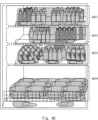
- FIG. 4B is a diagram showing an example of the second image area.
- the result of applying the second model to the item shelf image of FIG. 4A is shown in FIG. 4B.
- the shaded area corresponds to the second image area.
- the second model is not applied to shelf level image area SA14, where items are placed in a horizontally laid position, but for reference, the result of applying the second model to shelf level image area SA14 is also shown in FIG. 4B.
- the second model is able to accurately detect the item group image area corresponding to the plastic bottles in the images of the top three shelves.
- the second model can accurately detect even image areas corresponding to narrow empty spaces such as those sandwiched between two item group image areas.
- FIG. 4C is a diagram showing an example of the first image area.
- the shaded area in shelf level image area SA14 corresponds to the first image area.
- the first model is not applied to shelf level image areas SA11, SA12, and SA13, where the posture in which an item is placed is upright, but for reference, FIG. 4C also shows the results of applying the second model to shelf level image areas SA11, SA12, and SA13.
- model 1 is able to accurately detect not only the item group image area corresponding to the PET bottles located at the front in shelf level image area SA14 (i.e., the image of the bottom shelf level), but also the item group image area corresponding to the PET bottles located at the back.
- model 1 may detect image area SP1, which corresponds to a narrow empty space sandwiched between two item group image areas, as part of the item group image area.
- the determination unit 25 in the detection device 20 determines the "second model” as the "model in use” for shelf image areas corresponding to shelves where the posture on which an item is placed is determined to be upright.
- the determination unit 25 also determines the "first model” as the "model in use” for shelf image areas corresponding to shelves where the posture on which an item is placed is determined to be lying on its side.
- the second model is a model that identifies a second image area that corresponds to an image of a group of items placed at the front in the target image.
- the first model is a model that identifies a first image area in the target image based on the space mainly occupied by the items.
- the configuration of the detection device 20 can improve the detection accuracy of the item group image area. That is, for example, in a shelf image area corresponding to a shelf where the posture of the item is determined to be lying on its side, it is highly likely that even items located at the back are captured. When the second model is applied to such a shelf image area, it is possible that the image area corresponding to the item located at the back cannot be detected with high accuracy. On the other hand, when the first model is applied to such a shelf image area, it is highly likely that the image area corresponding to the item located at the back can be detected with high accuracy. In contrast, in a shelf image area where the posture of the item is determined to be standing, it is highly likely that almost no items located at the back are captured.
- the second model When the second model is applied to such a shelf image area, it is highly likely that the image area corresponding to the product group located at the front can be detected with high accuracy. Therefore, one model can compensate for the weak detection of the detection target of the other model, so that the detection accuracy of the item group image area can be improved.
- the determination unit 23 determines that the posture in which the item is placed on the shelf corresponding to the target shelf image area is an upright posture (i.e., the first posture) when the average value for the target shelf image area is equal to or greater than the reference value for the target shelf image area. Then, it has been explained that the determination unit 23 determines that the posture in which the item is placed on the shelf corresponding to the target shelf image area is a horizontal posture (i.e., the second posture) when the average value for the target shelf image area is less than the reference value for the target shelf image area.
- the present disclosure is not limited to this.
- the determination unit 23 may determine the posture in which an item is placed on a shelf corresponding to each shelf image area based on the ratio of the length to the width of the image of the single item detected in each shelf image area. For example, if the height direction of the item shelf is defined as the length and the direction perpendicular to that is defined as the width, the length of the image of the single item corresponding to the upright PET bottle is longer than the width, so the value of length/width is greater than 1. On the other hand, the length of the image of the single item corresponding to the PET bottle lying on its side is shorter than the width, so the value of length/width is less than 1. Therefore, the posture in which an item is placed on a shelf corresponding to each shelf image area can be determined based on the ratio of the length to the width of the image of the single item detected in each shelf image area.
- the third embodiment relates to identifying free space.
- FIG. 5 is a block diagram showing an example of a detection device in the third embodiment.
- the detection device 30 has a detection unit (first detection unit) 11, an identification unit (first identification unit) 12, a determination unit 13, a detection unit (second detection unit) 14, a decision unit 15, an integration unit 31, and a space identification unit 32.
- the integration unit 31 integrates a first image area in the image area to be processed detected by the detection unit 14 with a second image area in the image area to be processed detected by the detection unit 11 to obtain an "integrated image.”
- the second image area in the shelf level image areas SA11, SA12, and SA13 detected by the second model and the first image area in the shelf level image area SA14 detected by the first model are integrated to form an "integrated image.”
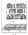
- Figure 6 is a diagram showing an example of an integrated image.
- the space identifying unit 32 identifies free space on each shelf level where no items are placed, based on the integrated image. For example, the space identifying unit 32 may identify free space by subtracting the integrated image from the shelf level image area. In FIG. 6, for example, the areas surrounded by rectangular frames (spaces SP1, SP2, SP3, and SP4) correspond to free space.
- the detection device 30 in the third embodiment identifies free space based on an integrated image obtained by applying the first model and the second model to the shelf image areas, which are the detection targets that the model is good at, and integrating the image areas obtained, so that free space can be identified with high accuracy.
- the description here is based on the assumption that the integration unit 31 and the space identification unit 32 are applied to the detection device 10 of the first embodiment, the present disclosure is not limited to this.
- the integration unit 31 and the space identification unit 32 may also be applied to the detection device 20 of the second embodiment.
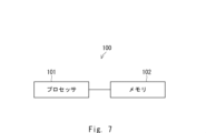
- Fig. 7 is a diagram showing an example of a hardware configuration of a detection device.
- the detection device 100 has a processor 101 and a memory 102.
- the processor 101 may be, for example, a microprocessor, a micro processing unit (MPU), or a central processing unit (CPU).
- the processor 101 may include a plurality of processors.
- the memory 102 is configured by a combination of a volatile memory and a non-volatile memory.
- the memory 102 may include a storage located away from the processor 101. In this case, the processor 101 may access the memory 102 via an I/O interface not shown.
- the detection devices 10, 20, and 30 of the first to third embodiments may each have the hardware configuration shown in FIG. 7.
- the detection units 11 and 21, the identification units 12 and 22, the determination units 13 and 23, the detection units 14 and 24, the decision units 15 and 25, the identification unit 26, the average calculation unit 27, the integration unit 31, and the space identification unit 32 of the detection devices 10, 20, and 30 of the first to third embodiments may be realized by the processor 101 reading and executing a program stored in the memory 102.
- the program can be stored using various types of non-transitory computer readable medium and supplied to the detection devices 10, 20, and 30.
- non-transitory computer readable media examples include magnetic recording media (e.g., flexible disks, magnetic tapes, hard disk drives) and magneto-optical recording media (e.g., magneto-optical disks). Further examples of non-transitory computer readable media include CD-ROM (Read Only Memory), CD-R, and CD-R/W. Further examples of non-transitory computer readable media include semiconductor memory. Semiconductor memory includes, for example, mask ROM, PROM (Programmable ROM), EPROM (Erasable PROM), flash ROM, and RAM (Random Access Memory).
- the program may also be provided to the detection devices 10, 20, and 30 by various types of transitory computer readable medium. Examples of transitory computer readable medium include electrical signals, optical signals, and electromagnetic waves. The transitory computer readable medium may provide the program to the detection devices 10, 20, and 30 via a wired communication path such as an electric wire or optical fiber, or a wireless communication path.
- a first detection unit that detects an image of a single item in a captured image of the item shelf; a first identification unit that identifies a plurality of shelf level image areas in the captured image, each of which corresponds to a plurality of shelf levels of the item shelf; a determination unit that determines a posture of an article placed on a shelf corresponding to each shelf level image area based on an image of a single article detected in each shelf level image area; a determination unit that determines a model to be used when each shelf image area is set as a processing target image area from among a plurality of models, each model being a model for detecting an article group image area and having different detection characteristics, based on the posture in which the article is placed; a second detection unit that detects an item group image area corresponding to an image of an item group in the processing target image area by applying the usage model to the processing target image area;
- a detection device comprising
- the detection device of claim 1 (Appendix 3) a second determination unit that determines a length of each shelf level image area corresponding to a height direction of the item shelf as a height of each shelf level image area; an average value calculation unit that calculates an average value of lengths corresponding to the height direction of at least one single article image detected by the first detection unit in each shelf level image area; Further comprising: The determination unit is if the average value for a target shelf level image area is equal to or greater than a value obtained by multiplying the height of the target shelf level image area by a predetermined ratio, it is determined that the position in which an item is placed on the shelf level corresponding to the target shelf level image area is an upright position; if the average value corresponding to the target shelf level image area is less than a value obtained by multiplying the height of the shelf level corresponding to the target shelf level image area by the predetermined ratio, it is determined that the position in which the item is placed on the shelf level corresponding to the target shelf level image area is a position in which the item is laid sideways;
- the detection device of claim 1 (Appendix 4) the determining unit determines a posture in which the item is placed on the shelf corresponding to each shelf level image area based on a ratio of length to width of the image of the single item detected in each shelf level image area. 2.
- the detection device of claim 1. (Appendix 5) the first identification unit identifies a line corresponding to a surface of the item in the image of the single item that contacts a shelf board of the item shelf, and identifies the plurality of shelf level image areas by dividing the photographed image by the identified line; 2.
- Appendix 6 The detection device of Appendix 2, further comprising an integration unit that integrates the first item group image area obtained by applying the first model to the processing target image area and the second item group image area obtained by applying the second model to the processing target image area to obtain an integrated image.
- Appendix 7 and a space identifying unit that identifies an empty space on each shelf where no article is placed based on the integrated image. 7.
- (Appendix 8) Detecting an image of a single item in a photographed image of the item shelf; Identifying a plurality of shelf level image areas in the captured image, each of which corresponds to a plurality of shelf levels of the item shelf; determining a posture of an article placed on a shelf corresponding to each shelf image area based on an image of the article alone detected in each shelf image area; determining a model to be used when each shelf image area is set as a processing target image area from among a plurality of models each of which is a model for detecting an article group image area and has different detection characteristics based on the posture in which the article is placed; detecting an item group image region in the target image region corresponding to an image of an item group by applying the usage model to the target image region;
- a detection method comprising: (Appendix 9)
- the plurality of models include a first model that identifies a first item group image area based on an item main occupation space that is mainly occupied by the item group in the target image, and a
- (Appendix 10) Detecting an image of a single item in a photographed image of the item shelf; Identifying a plurality of shelf level image areas in the captured image, each of which corresponds to a plurality of shelf levels of the item shelf; determining a posture of an article placed on a shelf corresponding to each shelf image area based on an image of the article alone detected in each shelf image area; determining a model to be used when each shelf image area is set as a processing target image area from among a plurality of models each of which is a model for detecting an article group image area and has different detection characteristics based on the posture in which the article is placed; detecting an item group image region in the target image region corresponding to an image of an item group by applying the usage model to the target image region;
- the plurality of models include a first model that identifies a first item group image area
- Detection device 11 Detection unit (first detection unit) 12 Specific Section (First Specific Section) 13 Determination unit 14 Detection unit (second detection unit) 15 Determination unit 20 Detection device 21 Detection unit (first detection unit) 22 Specific Section (First Specific Section) 23 Determination unit 24 Detection unit (second detection unit) 25 Determination Department 26 Specification Department (Second Specification Department) 27 Average value calculation unit 30 Detection device 31 Integration unit 32 Space identification unit
Landscapes
- Engineering & Computer Science (AREA)
- Computer Vision & Pattern Recognition (AREA)
- Physics & Mathematics (AREA)
- General Physics & Mathematics (AREA)
- Theoretical Computer Science (AREA)
- Image Analysis (AREA)
Abstract
Description
物品棚が撮影された撮影画像における物品単体についての物品単体画像を検知する第1検知部と、
前記撮影画像において前記物品棚の複数の棚段にそれぞれ対応する複数の棚段画像領域を特定する第1特定部と、
各棚段画像領域にて検知された物品単体画像に基づいて、各棚段画像領域に対応する棚段にて物品が置かれる姿勢を判定する判定部と、
前記物品が置かれる姿勢に基づいて、各モデルが物品群画像領域を検知するためのモデルであり且つ互いに検知特性の異なる複数のモデルのうちから、各棚段画像領域を処理対象画像領域にしたときの使用モデルを決定する決定部と、
前記処理対象画像領域に対して前記使用モデルを適用することによって、前記処理対象画像領域における物品群の画像に対応する物品群画像領域を検知する第2検知部と、
を具備する。
物品棚が撮影された撮影画像における物品単体についての物品単体画像を検知することと、
前記撮影画像において前記物品棚の複数の棚段にそれぞれ対応する複数の棚段画像領域を特定することと、
各棚段画像領域にて検知された物品単体画像に基づいて、各棚段画像領域に対応する棚段にて物品が置かれる姿勢を判定することと、
前記物品が置かれる姿勢に基づいて、各モデルが物品群画像領域を検知するためのモデルであり且つ互いに検知特性の異なる複数のモデルのうちから、各棚段画像領域を処理対象画像領域にしたときの使用モデルを決定することと、
前記処理対象画像領域に対して前記使用モデルを適用することによって、前記処理対象画像領域における物品群の画像に対応する物品群画像領域を検知することと、
を含む。
物品棚が撮影された撮影画像における物品単体についての物品単体画像を検知することと、
前記撮影画像において前記物品棚の複数の棚段にそれぞれ対応する複数の棚段画像領域を特定することと、
各棚段画像領域にて検知された物品単体画像に基づいて、各棚段画像領域に対応する棚段にて物品が置かれる姿勢を判定することと、
前記物品が置かれる姿勢に基づいて、各モデルが物品群画像領域を検知するためのモデルであり且つ互いに検知特性の異なる複数のモデルのうちから、各棚段画像領域を処理対象画像領域にしたときの使用モデルを決定することと、
前記処理対象画像領域に対して前記使用モデルを適用することによって、前記処理対象画像領域における物品群の画像に対応する物品群画像領域を検知することと、
を含む処理を、検知装置に実行させるプログラムを格納している。
図1は、第1実施形態における検知装置の一例を示すブロック図である。図1において検知装置10は、検知部(第1検知部)11と、特定部(第1特定部)12と、判定部13と、検知部(第2検知部)14と、決定部15とを有している。この撮影画像は、例えば、物品棚が撮影された物品棚画像である。以下では、撮影画像が物品棚画像であることを前提に説明する。この物品棚は、複数の棚段を有している。
以上の構成を有する検知装置10の処理動作の一例について説明する。図2は、第1実施形態における検知装置の処理動作の一例を示すフローチャートである。
第2実施形態は、第1実施形態の内容をより具体化する実施形態に関する。
- 物品単体の一側面の全体が撮影された画像。
- 物品棚画像において各棚段の最前列に並べられた物品群の物品群画像に対応する画像領域を「物品群画像領域」として指定した、物品棚画像。
- 物品単体の一側面の全体が撮影された画像。
- 物品棚画像において各棚段の最前列に並べられた物品群の物品群画像に対応する画像領域を「物品群画像領域」として指定した、物品棚画像。
- 物品棚画像において「真の背景に相当する画像(以下では、「真背景画像」と呼ぶことがある)」に対応する画像領域を「真背景画像領域」として指定した、物品棚画像。
以上の説明では、判定部23は、対象の棚段画像領域についての平均値が、対象の棚段画像領域についての基準値以上である場合、対象の棚段画像領域に対応する棚段では、物品が置かれる姿勢は立った姿勢(つまり、第1姿勢)であると判定するものとして説明を行った。そして、対象の棚段画像領域に対応する平均値が対象の棚段画像領域についての基準値未満である場合、判定部23は、対象の棚段画像領域に対応する棚段では、物品が置かれる姿勢は横向きに寝かされた姿勢(つまり、第2姿勢)であると判定するものとして説明を行った。しかしながら、本開示は、これに限定されるものではない。
第3実施形態は、空きスペースの特定に関する。
図7は、検知装置のハードウェア構成例を示す図である。図7において検知装置100は、プロセッサ101と、メモリ102とを有している。プロセッサ101は、例えば、マイクロプロセッサ、MPU(Micro Processing Unit)、又はCPU(Central Processing Unit)であってもよい。プロセッサ101は、複数のプロセッサを含んでもよい。メモリ102は、揮発性メモリ及び不揮発性メモリの組み合わせによって構成される。メモリ102は、プロセッサ101から離れて配置されたストレージを含んでもよい。この場合、プロセッサ101は、図示されていないI/Oインタフェースを介してメモリ102にアクセスしてもよい。
(付記1)
物品棚が撮影された撮影画像における物品単体についての物品単体画像を検知する第1検知部と、
前記撮影画像において前記物品棚の複数の棚段にそれぞれ対応する複数の棚段画像領域を特定する第1特定部と、
各棚段画像領域にて検知された物品単体画像に基づいて、各棚段画像領域に対応する棚段にて物品が置かれる姿勢を判定する判定部と、
前記物品が置かれる姿勢に基づいて、各モデルが物品群画像領域を検知するためのモデルであり且つ互いに検知特性の異なる複数のモデルのうちから、各棚段画像領域を処理対象画像領域にしたときの使用モデルを決定する決定部と、
前記処理対象画像領域に対して前記使用モデルを適用することによって、前記処理対象画像領域における物品群の画像に対応する物品群画像領域を検知する第2検知部と、
を具備する検知装置。
(付記2)
前記複数のモデルは、対象画像において物品群が主に占有する物品主占有空間に基づく第1物品群画像領域を識別する第1モデルと、対象画像において前側に配置された物品群の画像に対応する第2物品群画像領域を識別する第2モデルとを含み、
前記決定部は、
前記物品が置かれる姿勢が立った姿勢であると判定された棚段に対応する棚段画像領域については、前記第2モデルを前記使用モデルとして決定し、
前記物品が置かれる姿勢が横向きに寝かされた姿勢であると判定された棚段に対応する棚段画像領域ついては、前記第1モデルを前記使用モデルとして決定する、
付記1記載の検知装置。
(付記3)
前記物品棚の高さ方向に対応する各棚段画像領域の長さを、各棚段画像領域の高さとして特定する第2特定部と、
各棚段画像領域における前記第1検知部にて検知された少なくとも1つの物品単体画像の、前記高さ方向に対応する長さの平均値を算出する平均値算出部と、
をさらに具備し、
前記判定部は、
対象の棚段画像領域についての前記平均値が、前記対象の棚段画像領域の高さに所定割合を乗算して得られる値以上である場合、前記対象の棚段画像領域に対応する前記棚段では、物品が置かれる姿勢は立った姿勢であると判定し、
前記対象の棚段画像領域に対応する前記平均値が前記対象の棚段画像領域に対応する前記棚段の高さに前記所定割合を乗算して得られる値未満である場合、前記対象の棚段画像領域に対応する前記棚段では、物品が置かれる姿勢は横向きに寝かされた姿勢であると判定する、
付記1記載の検知装置。
(付記4)
前記判定部は、各棚段画像領域にて検知された物品単体画像の縦横の長さの比に基づいて、各棚段画像領域に対応する棚段にて前記物品が置かれる姿勢を判定する、
付記1記載の検知装置。
(付記5)
前記第1特定部は、前記物品単体画像における前記物品棚の棚板に接する物品の面に対応するラインを特定し、前記特定されたラインによって前記撮影画像を分割することによって、前記複数の棚段画像領域を特定する、
付記1記載の検知装置。
(付記6)
前記処理対象画像領域に対して前記第1モデルを適用することによって得られた前記第1物品群画像領域と前記処理対象画像領域に対して前記第2モデルを適用することによって得られた前記第2物品群画像領域とを統合して統合画像を得る統合部をさらに具備する、付記2記載の検知装置。
(付記7)
前記統合画像に基づいて、各棚段において物品が配置されていない空きスペースを特定するスペース特定部をさらに具備する、
付記6記載の検知装置。
(付記8)
物品棚が撮影された撮影画像における物品単体についての物品単体画像を検知することと、
前記撮影画像において前記物品棚の複数の棚段にそれぞれ対応する複数の棚段画像領域を特定することと、
各棚段画像領域にて検知された物品単体画像に基づいて、各棚段画像領域に対応する棚段にて物品が置かれる姿勢を判定することと、
前記物品が置かれる姿勢に基づいて、各モデルが物品群画像領域を検知するためのモデルであり且つ互いに検知特性の異なる複数のモデルのうちから、各棚段画像領域を処理対象画像領域にしたときの使用モデルを決定することと、
前記処理対象画像領域に対して前記使用モデルを適用することによって、前記処理対象画像領域における物品群の画像に対応する物品群画像領域を検知することと、
を含む検知方法。
(付記9)
前記複数のモデルは、対象画像において物品群が主に占有する物品主占有空間に基づく第1物品群画像領域を識別する第1モデルと、対象画像において前側に配置された物品群の画像に対応する第2物品群画像領域を識別する第2モデルとを含み、
前記決定することは、
前記物品が置かれる姿勢が立った姿勢であると判定された棚段に対応する棚段画像領域については、前記第2モデルを前記使用モデルとして決定することと、
前記物品が置かれる姿勢が横向きに寝かされた姿勢であると判定された棚段に対応する棚段画像領域ついては、前記第1モデルを前記使用モデルとして決定することと、
を含む、
付記8記載の検知方法。
(付記10)
物品棚が撮影された撮影画像における物品単体についての物品単体画像を検知することと、
前記撮影画像において前記物品棚の複数の棚段にそれぞれ対応する複数の棚段画像領域を特定することと、
各棚段画像領域にて検知された物品単体画像に基づいて、各棚段画像領域に対応する棚段にて物品が置かれる姿勢を判定することと、
前記物品が置かれる姿勢に基づいて、各モデルが物品群画像領域を検知するためのモデルであり且つ互いに検知特性の異なる複数のモデルのうちから、各棚段画像領域を処理対象画像領域にしたときの使用モデルを決定することと、
前記処理対象画像領域に対して前記使用モデルを適用することによって、前記処理対象画像領域における物品群の画像に対応する物品群画像領域を検知することと、
を含む処理を、検知装置に実行させるプログラムが格納された非一時的なコンピュータ可読媒体。
(付記11)
前記複数のモデルは、対象画像において物品群が主に占有する物品主占有空間に基づく第1物品群画像領域を識別する第1モデルと、対象画像において前側に配置された物品群の画像に対応する第2物品群画像領域を識別する第2モデルとを含み、
前記決定することは、
前記物品が置かれる姿勢が立った姿勢であると判定された棚段に対応する棚段画像領域については、前記第2モデルを前記使用モデルとして決定することと、
前記物品が置かれる姿勢が横向きに寝かされた姿勢であると判定された棚段に対応する棚段画像領域ついては、前記第1モデルを前記使用モデルとして決定することと、
を含む、
付記10記載の非一時的なコンピュータ可読媒体。
11 検知部(第1検知部)
12 特定部(第1特定部)
13 判定部
14 検知部(第2検知部)
15 決定部
20 検知装置
21 検知部(第1検知部)
22 特定部(第1特定部)
23 判定部
24 検知部(第2検知部)
25 決定部
26 特定部(第2特定部)
27 平均値算出部
30 検知装置
31 統合部
32 スペース特定部
Claims (11)
- 物品棚が撮影された撮影画像における物品単体についての物品単体画像を検知する第1検知部と、
前記撮影画像において前記物品棚の複数の棚段にそれぞれ対応する複数の棚段画像領域を特定する第1特定部と、
各棚段画像領域にて検知された物品単体画像に基づいて、各棚段画像領域に対応する棚段にて物品が置かれる姿勢を判定する判定部と、
前記物品が置かれる姿勢に基づいて、各モデルが物品群画像領域を検知するためのモデルであり且つ互いに検知特性の異なる複数のモデルのうちから、各棚段画像領域を処理対象画像領域にしたときの使用モデルを決定する決定部と、
前記処理対象画像領域に対して前記使用モデルを適用することによって、前記処理対象画像領域における物品群の画像に対応する物品群画像領域を検知する第2検知部と、
を具備する検知装置。 - 前記複数のモデルは、対象画像において物品群が主に占有する物品主占有空間に基づく第1物品群画像領域を識別する第1モデルと、対象画像において前側に配置された物品群の画像に対応する第2物品群画像領域を識別する第2モデルとを含み、
前記決定部は、
前記物品が置かれる姿勢が立った姿勢であると判定された棚段に対応する棚段画像領域については、前記第2モデルを前記使用モデルとして決定し、
前記物品が置かれる姿勢が横向きに寝かされた姿勢であると判定された棚段に対応する棚段画像領域ついては、前記第1モデルを前記使用モデルとして決定する、
請求項1記載の検知装置。 - 前記物品棚の高さ方向に対応する各棚段画像領域の長さを、各棚段画像領域の高さとして特定する第2特定部と、
各棚段画像領域における前記第1検知部にて検知された少なくとも1つの物品単体画像の、前記高さ方向に対応する長さの平均値を算出する平均値算出部と、
をさらに具備し、
前記判定部は、
対象の棚段画像領域についての前記平均値が、前記対象の棚段画像領域の高さに所定割合を乗算して得られる値以上である場合、前記対象の棚段画像領域に対応する前記棚段では、物品が置かれる姿勢は立った姿勢であると判定し、
前記対象の棚段画像領域に対応する前記平均値が前記対象の棚段画像領域に対応する前記棚段の高さに前記所定割合を乗算して得られる値未満である場合、前記対象の棚段画像領域に対応する前記棚段では、物品が置かれる姿勢は横向きに寝かされた姿勢であると判定する、
請求項1記載の検知装置。 - 前記判定部は、各棚段画像領域にて検知された物品単体画像の縦横の長さの比に基づいて、各棚段画像領域に対応する棚段にて前記物品が置かれる姿勢を判定する、
請求項1記載の検知装置。 - 前記第1特定部は、前記物品単体画像における前記物品棚の棚板に接する物品の面に対応するラインを特定し、前記特定されたラインによって前記撮影画像を分割することによって、前記複数の棚段画像領域を特定する、
請求項1記載の検知装置。 - 前記処理対象画像領域に対して前記第1モデルを適用することによって得られた前記第1物品群画像領域と前記処理対象画像領域に対して前記第2モデルを適用することによって得られた前記第2物品群画像領域とを統合して統合画像を得る統合部をさらに具備する、請求項2記載の検知装置。
- 前記統合画像に基づいて、各棚段において物品が配置されていない空きスペースを特定するスペース特定部をさらに具備する、
請求項6記載の検知装置。 - 物品棚が撮影された撮影画像における物品単体についての物品単体画像を検知することと、
前記撮影画像において前記物品棚の複数の棚段にそれぞれ対応する複数の棚段画像領域を特定することと、
各棚段画像領域にて検知された物品単体画像に基づいて、各棚段画像領域に対応する棚段にて物品が置かれる姿勢を判定することと、
前記物品が置かれる姿勢に基づいて、各モデルが物品群画像領域を検知するためのモデルであり且つ互いに検知特性の異なる複数のモデルのうちから、各棚段画像領域を処理対象画像領域にしたときの使用モデルを決定することと、
前記処理対象画像領域に対して前記使用モデルを適用することによって、前記処理対象画像領域における物品群の画像に対応する物品群画像領域を検知することと、
を含む検知方法。 - 前記複数のモデルは、対象画像において物品群が主に占有する物品主占有空間に基づく第1物品群画像領域を識別する第1モデルと、対象画像において前側に配置された物品群の画像に対応する第2物品群画像領域を識別する第2モデルとを含み、
前記決定することは、
前記物品が置かれる姿勢が立った姿勢であると判定された棚段に対応する棚段画像領域については、前記第2モデルを前記使用モデルとして決定することと、
前記物品が置かれる姿勢が横向きに寝かされた姿勢であると判定された棚段に対応する棚段画像領域ついては、前記第1モデルを前記使用モデルとして決定することと、
を含む、
請求項8記載の検知方法。 - 物品棚が撮影された撮影画像における物品単体についての物品単体画像を検知することと、
前記撮影画像において前記物品棚の複数の棚段にそれぞれ対応する複数の棚段画像領域を特定することと、
各棚段画像領域にて検知された物品単体画像に基づいて、各棚段画像領域に対応する棚段にて物品が置かれる姿勢を判定することと、
前記物品が置かれる姿勢に基づいて、各モデルが物品群画像領域を検知するためのモデルであり且つ互いに検知特性の異なる複数のモデルのうちから、各棚段画像領域を処理対象画像領域にしたときの使用モデルを決定することと、
前記処理対象画像領域に対して前記使用モデルを適用することによって、前記処理対象画像領域における物品群の画像に対応する物品群画像領域を検知することと、
を含む処理を、検知装置に実行させるプログラムが格納された非一時的なコンピュータ可読媒体。 - 前記複数のモデルは、対象画像において物品群が主に占有する物品主占有空間に基づく第1物品群画像領域を識別する第1モデルと、対象画像において前側に配置された物品群の画像に対応する第2物品群画像領域を識別する第2モデルとを含み、
前記決定することは、
前記物品が置かれる姿勢が立った姿勢であると判定された棚段に対応する棚段画像領域については、前記第2モデルを前記使用モデルとして決定することと、
前記物品が置かれる姿勢が横向きに寝かされた姿勢であると判定された棚段に対応する棚段画像領域ついては、前記第1モデルを前記使用モデルとして決定することと、
を含む、
請求項10記載の非一時的なコンピュータ可読媒体。
Priority Applications (2)
| Application Number | Priority Date | Filing Date | Title |
|---|---|---|---|
| JP2025509328A JPWO2024201706A5 (ja) | 2023-03-28 | 検知装置、検知方法、及びプログラム | |
| PCT/JP2023/012482 WO2024201706A1 (ja) | 2023-03-28 | 2023-03-28 | 検知装置、検知方法、及び非一時的なコンピュータ可読媒体 |
Applications Claiming Priority (1)
| Application Number | Priority Date | Filing Date | Title |
|---|---|---|---|
| PCT/JP2023/012482 WO2024201706A1 (ja) | 2023-03-28 | 2023-03-28 | 検知装置、検知方法、及び非一時的なコンピュータ可読媒体 |
Publications (1)
| Publication Number | Publication Date |
|---|---|
| WO2024201706A1 true WO2024201706A1 (ja) | 2024-10-03 |
Family
ID=92903547
Family Applications (1)
| Application Number | Title | Priority Date | Filing Date |
|---|---|---|---|
| PCT/JP2023/012482 Ceased WO2024201706A1 (ja) | 2023-03-28 | 2023-03-28 | 検知装置、検知方法、及び非一時的なコンピュータ可読媒体 |
Country Status (1)
| Country | Link |
|---|---|
| WO (1) | WO2024201706A1 (ja) |
Citations (4)
| Publication number | Priority date | Publication date | Assignee | Title |
|---|---|---|---|---|
| JP2016071782A (ja) * | 2014-10-01 | 2016-05-09 | 辛東主 | 商品陳列情報集計システム |
| JP2021196885A (ja) * | 2020-06-15 | 2021-12-27 | パナソニックIpマネジメント株式会社 | 監視装置、監視方法、及び、コンピュータプログラム |
| WO2022024364A1 (ja) * | 2020-07-31 | 2022-02-03 | 日本電気株式会社 | 商品検知装置、商品検知システム、商品検知方法および記録媒体 |
| JP2022084417A (ja) * | 2020-11-26 | 2022-06-07 | 株式会社野村総合研究所 | 商品販売システム |
-
2023
- 2023-03-28 WO PCT/JP2023/012482 patent/WO2024201706A1/ja not_active Ceased
Patent Citations (4)
| Publication number | Priority date | Publication date | Assignee | Title |
|---|---|---|---|---|
| JP2016071782A (ja) * | 2014-10-01 | 2016-05-09 | 辛東主 | 商品陳列情報集計システム |
| JP2021196885A (ja) * | 2020-06-15 | 2021-12-27 | パナソニックIpマネジメント株式会社 | 監視装置、監視方法、及び、コンピュータプログラム |
| WO2022024364A1 (ja) * | 2020-07-31 | 2022-02-03 | 日本電気株式会社 | 商品検知装置、商品検知システム、商品検知方法および記録媒体 |
| JP2022084417A (ja) * | 2020-11-26 | 2022-06-07 | 株式会社野村総合研究所 | 商品販売システム |
Also Published As
| Publication number | Publication date |
|---|---|
| JPWO2024201706A1 (ja) | 2024-10-03 |
Similar Documents
| Publication | Publication Date | Title |
|---|---|---|
| CN110472515B (zh) | 货架商品检测方法及系统 | |
| US6466695B1 (en) | Procedure for automatic analysis of images and image sequences based on two-dimensional shape primitives | |
| US8812344B1 (en) | Method and system for determining the impact of crowding on retail performance | |
| US9294665B2 (en) | Feature extraction apparatus, feature extraction program, and image processing apparatus | |
| CN110472486B (zh) | 一种货架障碍物识别方法、装置、设备及可读存储介质 | |
| CN109214389B (zh) | 一种目标识别方法、计算机装置及可读存储介质 | |
| US9292130B2 (en) | Optical touch system and object detection method therefor | |
| CN111161346B (zh) | 将商品在货架中进行分层的方法、装置和电子设备 | |
| JP7145224B2 (ja) | 目標対象の認識方法、装置及びシステム | |
| US8442327B2 (en) | Application of classifiers to sub-sampled integral images for detecting faces in images | |
| CN113918744B (zh) | 相似图像检索方法、装置、存储介质及计算机程序产品 | |
| US20150146991A1 (en) | Image processing apparatus and image processing method of identifying object in image | |
| US20120087574A1 (en) | Learning device, learning method, identification device, identification method, and program | |
| JP2014515485A (ja) | 構造化された照明を用いる3dスキャナ | |
| US20120262423A1 (en) | Image processing method for optical touch system | |
| CN109388926A (zh) | 处理生物特征图像的方法和包括该方法的电子设备 | |
| CN101187984A (zh) | 一种图像检测方法及装置 | |
| US8693740B1 (en) | System and method for face detection in digital images | |
| JP7459947B2 (ja) | 商品検知装置、商品検知システム、商品検知方法および商品検知プログラム | |
| WO2024201706A1 (ja) | 検知装置、検知方法、及び非一時的なコンピュータ可読媒体 | |
| US20120057751A1 (en) | Particle Tracking Methods | |
| JP7769919B2 (ja) | 情報処理装置、情報処理方法及びコンピュータプログラム | |
| WO2024201704A1 (ja) | 検知装置、検知方法、及び非一時的なコンピュータ可読媒体 | |
| WO2024201705A1 (ja) | 検知装置、検知方法、及び非一時的なコンピュータ可読媒体 | |
| US10521653B2 (en) | Image processing device, image processing method, and storage medium |
Legal Events
| Date | Code | Title | Description |
|---|---|---|---|
| 121 | Ep: the epo has been informed by wipo that ep was designated in this application |
Ref document number: 23930346 Country of ref document: EP Kind code of ref document: A1 |
|
| ENP | Entry into the national phase |
Ref document number: 2025509328 Country of ref document: JP Kind code of ref document: A |
|
| WWE | Wipo information: entry into national phase |
Ref document number: 2025509328 Country of ref document: JP |
|
| NENP | Non-entry into the national phase |
Ref country code: DE |
|
| 122 | Ep: pct application non-entry in european phase |
Ref document number: 23930346 Country of ref document: EP Kind code of ref document: A1 |