WO2024201608A1 - 推定装置 - Google Patents
推定装置 Download PDFInfo
- Publication number
- WO2024201608A1 WO2024201608A1 PCT/JP2023/011973 JP2023011973W WO2024201608A1 WO 2024201608 A1 WO2024201608 A1 WO 2024201608A1 JP 2023011973 W JP2023011973 W JP 2023011973W WO 2024201608 A1 WO2024201608 A1 WO 2024201608A1
- Authority
- WO
- WIPO (PCT)
- Prior art keywords
- signal
- noise
- optical
- estimation
- representative signal
- Prior art date
- Legal status (The legal status is an assumption and is not a legal conclusion. Google has not performed a legal analysis and makes no representation as to the accuracy of the status listed.)
- Ceased
Links
Images





Classifications
-
- H—ELECTRICITY
- H04—ELECTRIC COMMUNICATION TECHNIQUE
- H04B—TRANSMISSION
- H04B10/00—Transmission systems employing electromagnetic waves other than radio-waves, e.g. infrared, visible or ultraviolet light, or employing corpuscular radiation, e.g. quantum communication
- H04B10/07—Arrangements for monitoring or testing transmission systems; Arrangements for fault measurement of transmission systems
- H04B10/075—Arrangements for monitoring or testing transmission systems; Arrangements for fault measurement of transmission systems using an in-service signal
- H04B10/079—Arrangements for monitoring or testing transmission systems; Arrangements for fault measurement of transmission systems using an in-service signal using measurements of the data signal
-
- H—ELECTRICITY
- H04—ELECTRIC COMMUNICATION TECHNIQUE
- H04J—MULTIPLEX COMMUNICATION
- H04J14/00—Optical multiplex systems
- H04J14/02—Wavelength-division multiplex systems
Definitions
- the present invention relates to an estimation device, an estimation method, a recording medium, and a selection device.
- OSNR optical signal to noise ratio
- Patent Document 1 discloses a method for efficiently narrowing down and estimating the maximum/minimum OSNR of the OSNRs of optical signals transmitted over the same path. Specifically, according to Patent Document 1, the method narrows down the estimated OSNR by using Bayesian optimization to determine the wavelength to be estimated next.
- one of the objectives of the present invention is to provide an estimation device, an estimation method, a recording medium, and a selection device that can solve the above-mentioned problems.
- an estimation device includes: a selection unit that selects a representative signal from among the optical signals that are candidates for estimation based on noise characteristic information indicating noise characteristics in the optical amplifier; an estimation unit that estimates an optical signal-to-noise ratio for the representative signal selected by the selection unit;
- an estimation method includes: An information processing device, selecting a representative signal from among the candidate optical signals based on noise characteristic information indicating noise characteristics in the optical amplifier; The optical signal-to-noise ratio is estimated for the selected representative signal.
- a recording medium includes: In the information processing device, selecting a representative signal from among the candidate optical signals based on noise characteristic information indicating noise characteristics in the optical amplifier;
- the present invention is a computer-readable recording medium having recorded thereon a program for implementing a process for estimating an optical signal-to-noise ratio for a selected representative signal.
- a selection device comprises:
- the optical amplifier is configured to include a selection unit that acquires noise characteristic information indicating the noise characteristics in the optical amplifier, and selects a representative signal for estimating the optical signal-to-noise ratio from among candidate optical signals for estimating the optical signal-to-noise ratio based on the acquired noise characteristic information.
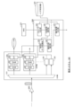
- FIG. 1 is a diagram illustrating an example of the configuration of an estimation system.
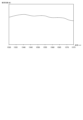
- FIG. 4 is a diagram illustrating an example of noise characteristic information.
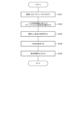
- 13 is a flowchart showing an example of the operation of the terminal device.
- FIG. 13 is a diagram illustrating another example of the configuration of a terminal device.
- FIG. 11 is a diagram illustrating an example of a hardware configuration of an estimation device according to a second embodiment of the present disclosure.
- FIG. 2 is a block diagram showing a configuration example of an estimation device.
- FIG. 2 is a block diagram showing a configuration example of a selection device.
- FIG. 1 is a diagram for explaining an example of an optical signal to noise ratio (OSNR).
- FIG. 2 is a diagram showing a configuration example of an estimation system 100.
- Fig. 3 is a diagram showing an example of noise characteristic information 420.
- Fig. 4 is a flowchart showing an operation example of a terminal device 300.
- Fig. 5 is a diagram showing another configuration example of the terminal device 300.
- Non-Patent Document 1 is an example of a document that describes the estimation of communication quality based on signal information.
- the estimation system 100 of the present disclosure can replace the estimation of the optical signal-to-noise ratio of multiple optical signals transmitted over the same path with an estimated value of a representative optical signal. For example, the estimation system 100 identifies a representative optical signal from multiple optical signals transmitted over the same path based on noise characteristic information 420 indicating the noise characteristics of the optical amplifier. Then, the estimation system 100 estimates the optical signal-to-noise ratio for the identified optical signal. Note that the estimation system 100 may identify only one representative optical signal, or may identify multiple representative optical signals.
- the optical signal-to-noise ratio is a value that represents the ratio of signal strength to noise strength.
- the optical signal-to-noise ratio deteriorates when noise is added due to amplified spontaneous emission (ASE) added by an optical amplifier.
- Figure 1 shows an example of the relationship between optical amplification and noise. Referring to Figure 1, it can be seen that in an optical network, noise originating from the optical amplifier is added each time the signal passes through an optical amplifier, deteriorating the optical signal-to-noise ratio.
- the estimation system 100 is a system that performs optical wavelength division multiplexing (WDM) communication, in which optical signals of multiple wavelengths, such as 96 or 128 wavelengths, are superimposed on an optical fiber for communication.
- WDM optical wavelength division multiplexing
- Figure 2 shows an example configuration of the estimation system 100.
- the estimation system 100 includes, for example, an amplifier 200, a terminal device 300, an NMS (Network Management System) 410, and noise characteristic information 420.
- NMS Network Management System
- Amplifier 200 is an optical amplifier that amplifies an optical signal. Amplifiers 200 are installed at arbitrary intervals on the transmission path according to the transmission distance of the optical signal.
- the amplifier 200 is an erbium-doped fiber amplifier (EDFA).
- EDFA erbium-doped fiber amplifier
- the amplifier 200 can amplify the signal strength of the optical signal by multiplexing the pump light and the signal light and passing the combined light through an optical fiber doped with erbium.
- the amplifier 200 amplifies the signal strength of the optical signal, it also introduces noise into the optical signal.
- the amplifier 200 may be an amplifier other than an erbium-doped fiber amplifier.
- the amplifier 200 may be an optical amplifier using a fiber doped with a rare earth other than erbium, such as praseodymium or thulium.
- the terminal device 300 is a processing device that receives an optical signal transmitted by the terminal device 300 located at the other side.
- the terminal device 300 can estimate an optical signal-to-noise ratio.
- the terminal device 300 has, for example, a splitter 310 and a receiver 320.
- the terminal device 300 may have a number of receivers 320 according to the number of wavelengths to be superimposed and transmitted.
- the terminal device 300 can have a group determination unit 330, a representative signal selection unit 340, a received optical data collection unit 350, a communication quality estimation unit 360, and an estimation result output unit 370.
- the terminal device 300 has a calculation unit such as a CPU (Central Processing Unit) and a storage device.
- the terminal device 300 may realize each of the above processing units by having the calculation unit execute a program stored in the storage device.
- the arithmetic processing unit may have a GPU (Graphic Processing Unit), a DSP (Digital Signal Processor), an MPU (Micro Processing Unit), an FPU (Floating point number Processing Unit), a PPU (Physics Processing Unit), a TPU (Tensor Processing Unit), a quantum processor, a microcontroller, or a combination of these.
- GPU Graphic Processing Unit
- DSP Digital Signal Processor
- MPU Micro Processing Unit
- FPU Floating point number Processing Unit
- PPU Physicals Processing Unit
- TPU Transsor Processing Unit
- quantum processor a microcontroller, or a combination of these.
- the demultiplexer 310 demultiplexes multiple optical signals of different wavelengths that have been transmitted through an optical fiber into individual wavelengths. For example, in optical wavelength division multiplexing communications, multiple wavelengths are superimposed and transmitted through an optical fiber. The demultiplexer 310 can demultiplex the multiple wavelengths that are superimposed and transmitted into individual wavelengths.
- the receiver 320 receives the optical signal split by the splitter 310 and performs OE (Optical signal/Electrical signal) conversion and AD (Analog/Digital) conversion.
- the receiver 320 has an OE conversion unit 321, an AD conversion unit 322, and a DSP (Digital Signal Processor) 323.
- the OE conversion unit 321 converts the optical signal received from the splitter 310 into an electrical signal.
- the AD conversion unit 322 converts the analog signal output by the OE conversion unit 321 into a digital signal.
- the DSP 323 performs a predetermined process based on the digital signal. For example, the DSP 323 can perform error correction coding processing and various processes required to estimate the optical signal-to-noise ratio. The processes performed by the DSP 323 may be general processes.
- the group determination unit 330 identifies optical signals of each wavelength received by the receiver 320 that have been transmitted via the same route. The group determination unit 330 then groups the optical signals so that optical signals transmitted via the same route belong to the same group. In other words, the group determination unit 330 groups the optical signals of each wavelength that are estimated candidates so that optical signals that have passed through the same optical fiber or amplifier 200 belong to the same group.
- the group determination unit 330 acquires route information and the like from the NMS 410, which manages optical communications transmitted through optical fiber, to identify optical signals of each wavelength received by the receiver 320 that were transmitted along the same route. The group determination unit 330 then performs grouping based on the identified results. In this way, the group determination unit 330 can group optical signals by acquiring route information and the like indicating the route along which each optical signal is transmitted from the NMS 410.
- the representative signal selection unit 340 selects a representative signal that represents each group that has been grouped by the group determination unit 330. In other words, the representative signal selection unit 340 selects a representative signal from among the optical signals that have been transmitted through the same path.
- the representative signal selection unit 340 may select one optical signal as the representative signal, or may select multiple optical signals.
- the representative signal selection unit 340 can refer to noise characteristic information 420 indicating the noise characteristics in the amplifier 200, which is an optical amplifier, and select a representative signal according to the reference result.
- FIG. 3 shows an example of noise characteristic information 420 when an erbium-doped fiber amplifier is used as the amplifier 200.
- the noise characteristic information 420 indicates a noise figure, which is a value according to the magnitude of the noise, for each wavelength.
- a larger noise figure indicates a larger noise. Therefore, for example, in the example of FIG. 3, it can be seen that the most noise occurs at wavelengths around 1540 nm.
- the representative signal selection unit 340 selects a representative signal by referring to the noise characteristic information 420 as described above and identifying the noise figure corresponding to each wavelength included in the same group. For example, the representative signal selection unit 340 identifies the noise figure corresponding to each wavelength included in the group. Then, the representative signal selection unit 340 can select the optical signal with the wavelength that has the highest identified noise figure as the representative signal.
- the representative signal selection unit 340 may select, as the representative signal, an optical signal other than the optical signal with the highest noise figure among the optical signals included in the same group. For example, the representative signal selection unit 340 may select, as the representative signal, an optical signal with the lowest noise figure among the optical signals included in the same group. The representative signal selection unit 340 may select, as the representative signal, an optical signal with a wavelength whose noise figure is in the middle among the optical signals included in the same group. The representative signal selection unit 340 may be configured to switch the representative signal to be selected at predetermined time intervals, or may select multiple optical signals as representative signals, such as selecting an optical signal with the highest noise figure and an optical signal with the lowest noise figure.
- the noise characteristic information 420 may include information indicating the noise characteristics of each wavelength for each type of amplifier 200 that may have different noise characteristics, such as the type of rare earth added to the amplifier 200, the manufacturer of the amplifier 200, and each product type.
- the representative signal selection unit 340 may be configured to use any method to determine the information indicating the noise characteristics to be used when selecting a representative signal from the information indicating the noise characteristics corresponding to each amplifier 200 present on the path. For example, the representative signal selection unit 340 may determine that the information indicating the noise characteristics corresponding to the amplifier 200 present closest to the terminal device 300 is to be used when selecting a representative signal.
- the representative signal selection unit 340 may also determine that the information indicating the noise characteristics corresponding to the most numerous type of amplifier 200 among the amplifiers 200 present on the path is to be used when selecting a representative signal.
- the representative signal selection unit 340 may select a representative signal using the information indicating the noise characteristics corresponding to each type of amplifier 200 present on the path. For example, the representative signal selection unit 340 may select a representative signal using the results of calculating the sum or average value of noise figures based on information indicating multiple noise characteristics.
- the received light data collection unit 350 collects signal information, such as constellation waveforms, for the optical signal of the wavelength selected as the representative signal by the representative signal selection unit 340.
- the communication quality estimation unit 360 estimates communication quality, such as estimating the signal-to-noise ratio, by inputting the signal information collected by the received light data collection unit 350 into a pre-trained model.
- the communication quality estimation unit 360 may perform the above estimation using known technology.
- the communication quality estimation unit 360 has a model that has been trained in advance using teacher data, etc., so as to output an estimated signal-to-noise ratio result, etc., in response to the input of signal information.
- the communication quality estimation unit 360 can obtain an estimated signal-to-noise ratio result, etc., by inputting signal information into such a trained model.
- the communication quality estimation unit 360 can estimate the signal-to-noise ratios of other optical signals belonging to the same group based on the result of estimation of the representative signal. For example, the communication quality estimation unit 360 can estimate the signal-to-noise ratios of other optical signals belonging to the same group as the estimated representative signal based on the noise characteristic information 420. For example, as described above, the noise figure for each wavelength can be specified by referring to the noise characteristic information 420. Therefore, the communication quality estimation unit 360 can estimate the signal-to-noise ratios of the other optical signals based on the signal-to-noise ratio of the representative signal by performing correction for each optical signal according to the difference in the noise figure between the representative signal and the other optical signals.
- the specific correction amount according to the difference in the noise figure may be set arbitrarily.
- the communication quality estimation unit 360 may estimate the maximum value or median value of the estimated signal-to-noise ratio as the signal-to-noise ratio of optical signals other than the representative signal.
- the communication quality estimation unit 360 may use the signal-to-noise ratio of the representative signal as the signal-to-noise ratio of an optical signal other than the representative signal.
- the estimation result output unit 370 outputs the results estimated by the communication quality estimation unit 360.
- the estimation result output unit 370 may display the results estimated by the communication quality estimation unit 360 on a screen display device, or may transmit the results estimated by the communication quality estimation unit 360 to an external device or the like.
- the estimation result output unit 370 can output the results estimated by the communication quality estimation unit 360 for each group determined by the group determination unit 330.
- the terminal device 300 selects a representative signal from among the optical signals transmitted through the same path, and estimates the signal-to-noise ratio for the selected representative signal. In addition, when making the above selection, the terminal device 300 can make the selection based on the noise characteristic information 420.
- NMS 410 manages optical communications transmitted through optical fiber.
- NMS 410 may be a general network management system.
- NMS 410 has route information indicating the route along which optical signals of each wavelength are transmitted.
- NMS 410 can transmit route information to terminal device 300 in response to instructions from terminal device 300, etc.
- Noise characteristic information 420 indicates the noise characteristics of amplifier 200, which is an optical amplifier. For example, in noise characteristic information 420, a noise figure, which is a value corresponding to the magnitude of noise, is indicated for each wavelength. As described above, FIG. 3 shows an example of noise characteristic information 420 when an erbium-doped fiber amplifier is used as amplifier 200. For example, information indicating the noise characteristics of each wavelength indicated by noise characteristic information 420 is obtained in advance by actually measuring the results of amplifying an optical signal using various types of amplifiers 200, and is stored in an external storage device, etc.
- the noise characteristic information 420 may include information indicating the noise characteristics of each wavelength for each type of amplifier 200 that may have different noise characteristics, such as the type of rare earth added to the amplifier 200, the manufacturer of the amplifier 200, and each product type.
- the noise characteristic information 420 may also include information indicating the noise characteristics originating from optical amplifiers other than those exemplified above.
- FIG. 4 is a flowchart showing an example of the operation of the terminal device 300.
- the group determination unit 330 groups the optical signals of each wavelength received by the receiver 320 so that the optical signals that have passed through the same optical fiber or amplifier 200 belong to the same group (step S101).
- the representative signal selection unit 340 selects a representative signal that represents each group for each group that has been grouped by the group determination unit 330.
- the representative signal selection unit 340 refers to the noise characteristic information 420 and selects a representative signal based on the results of the reference (step S102).
- the received light data collection unit 350 collects signal information, such as a constellation waveform, for the optical signal of the wavelength selected as the representative signal by the representative signal selection unit 340 (step S103).
- signal information such as a constellation waveform
- the communication quality estimation unit 360 estimates the signal-to-noise ratio by inputting the signal information collected by the received optical data collection unit 350 into a pre-trained model (step S104).
- the communication quality estimation unit 360 may also estimate the signal-to-noise ratio for other optical signals belonging to the same group based on the result of the estimation for the representative signal.
- the estimation result output unit 370 outputs the result estimated by the communication quality estimation unit 360 (step S105). For example, the estimation result output unit 370 may display the result estimated by the communication quality estimation unit 360 on a screen display device, or may transmit the result estimated by the communication quality estimation unit 360 to an external device or the like.
- the above is an example of the operation of the terminal device 300.
- the terminal device 300 has a representative signal selection unit 340 and a communication quality estimation unit 360.
- the communication quality estimation unit 360 can estimate the signal-to-noise ratio using the representative signal selected by the representative signal selection unit 340 from among the optical signals as a representative. This allows the terminal device 300 to reduce costs such as the amount of data when estimating the signal-to-noise ratio, the number of models to be managed, and computational resources.
- the terminal device 300 also has a group determination unit 330.
- the communication quality estimation unit 360 can estimate the signal-to-noise ratio for a representative signal selected from optical signals transmitted through the same path. As a result, more appropriate estimation can be performed while keeping costs down.
- the configuration of the terminal device 300 is not limited to the example shown in FIG. 2.
- FIG. 5 shows another example of the configuration of the terminal device 300.
- the terminal device 300 may be composed of a selection device having a group determination unit 330 and a representative signal selection unit 340, and a terminal device having a received light data collection unit 350, a communication quality estimation unit 360, and an estimation result output unit 370.
- the terminal device 300 may also have noise characteristic information 420 and the like in advance.
- Fig. 6 is a diagram showing a hardware configuration example of an estimation device 500.
- Fig. 7 is a block diagram showing a configuration example of the estimation device 500.
- Fig. 8 is a block diagram showing a configuration example of a selection device 600.
- an estimation device 500 that is an information processing device that estimates an optical signal to noise ratio will be described. Also, in the second embodiment of the present disclosure, a selection device 600 that selects an optical signal to be estimated will be described.
- Fig. 6 shows an example of a hardware configuration of the estimation device 500. Referring to Fig. 6, the estimation device 500 has, as an example, the following hardware configuration.
- ⁇ CPU Central Processing Unit
- 501 (arithmetic unit)
- ROM Read Only Memory
- RAM Random Access Memory
- Program group 504 loaded into RAM 503
- a storage device 505 for storing the programs 504
- a drive device 506 that reads and writes data from and to a recording medium 510 outside the information processing device.
- a communication interface 507 that connects to a communication network 511 outside the information processing device
- a bus 509 that connects each component
- the estimation device 500 can realize the functions of the selection unit 521 and estimation unit 522 shown in FIG. 7 by having the CPU 501 acquire and execute the program group 504.
- the program group 504 is stored in advance in the storage device 505 or ROM 502, for example, and is loaded into the RAM 503 or the like by the CPU 501 for execution as necessary.
- the program group 504 may be supplied to the CPU 501 via the communication network 511, or may be stored in advance in the recording medium 510, and the drive device 506 may read out the programs and supply them to the CPU 501.
- FIG. 6 shows an example of the hardware configuration of the estimation device 500.
- the hardware configuration of the estimation device 500 is not limited to the above-mentioned case.
- the estimation device 500 may be configured with only a part of the above-mentioned configuration, such as not having the drive device 506.
- the CPU 501 may be a GPU as exemplified in the first embodiment.
- the selection unit 521 selects a representative signal from among the optical signals that are candidates for estimation based on noise characteristic information that indicates the noise characteristics in the optical amplifier. For example, the selection unit 521 can select a representative signal based on information that indicates the noise characteristics in an optical amplifier that is present on the path along which the optical signal is transmitted.
- the estimation unit 522 estimates the optical signal-to-noise ratio for the representative signal selected by the selection unit 521.
- the estimation unit 522 may perform the above estimation using a known means, such as estimating the optical signal-to-noise ratio based on a model that has been learned in advance.
- the estimation device 500 has a selection unit 521 and an estimation unit 522.
- the estimation unit 522 can estimate the optical signal-to-noise ratio for the representative signal selected by the selection unit 521. This allows the estimation device 500 to reduce costs when estimating the signal-to-noise ratio.
- the above-mentioned estimation device 500 can be realized by incorporating a predetermined program into an information processing device such as the estimation device 500.
- a program that is another aspect of the present invention is a program for implementing a process in an information processing device such as the estimation device 500 to select a representative signal from optical signals that are estimation candidates based on noise characteristic information that indicates the noise characteristics in an optical amplifier, and estimate the optical signal-to-noise ratio for the selected representative signal.
- the estimation method executed by an information processing device such as the above-mentioned estimation device 500 is a method in which the information processing device selects a representative signal from among the optical signals that are estimation candidates based on noise characteristic information that indicates the noise characteristics in the optical amplifier, and estimates the optical signal-to-noise ratio for the selected representative signal.
- the invention is a program having the above-mentioned configuration, or a computer-readable recording medium having a program recorded thereon, or an estimation method, it can achieve the above-mentioned objective of the present disclosure by achieving the same actions and effects as the above-mentioned estimation device 500.
- the selection device 600 that selects the optical signal to be estimated can also achieve the above-mentioned object of the present disclosure, similar to the above-mentioned estimation device 500.
- FIG. 8 shows an example of the configuration of the selection device 600. Referring to FIG. 8, the selection device 600 has a selection unit 621. Note that the hardware configuration of the selection device 600 may be the same as that of the estimation device 500 described with reference to FIG. 6.
- the selection unit 621 acquires noise characteristic information indicating the noise characteristics in the optical amplifier, and selects a representative signal for estimating the optical signal-to-noise ratio from among the optical signals that are candidates for estimating the optical signal-to-noise ratio based on the acquired noise characteristic information. For example, the selection device 600 outputs information indicating the representative signal selected by the selection unit 621 to an external device. In response to this, the external device, such as an estimation device, can perform estimation on the representative signal.
- the selection device 600 can achieve the same action and effect as the estimation device 500 described above, and therefore can achieve the above-mentioned objective of the present disclosure.
- (Appendix 1) a selection unit that selects a representative signal from among the optical signals that are candidates for estimation based on noise characteristic information indicating noise characteristics in the optical amplifier; an estimation unit that estimates an optical signal-to-noise ratio for the representative signal selected by the selection unit;
- the estimation device according to claim 1, a group determination unit that groups optical signals that are candidates for estimation based on route information indicating a route along which the optical signals are transmitted;
- the selection unit selects a representative signal for each of the groups obtained by the group determination unit.
- (Appendix 3) 3.
- the estimation device according to claim 2 The group determination unit performs grouping based on the path information such that optical signals that have passed through the same fiber and the same optical amplifier belong to the same group.
- the estimation device further comprising: the noise characteristic information indicates a value corresponding to the noise magnitude for each wavelength, The selection unit selects a representative signal from among optical signals belonging to the same group based on a value corresponding to a noise magnitude indicated by the noise characteristic information. (Appendix 5) 5. The estimation device according to claim 4, The selection unit selects, from among the optical signals belonging to the same group, an optical signal having a highest value corresponding to a noise magnitude indicated by the noise characteristic information as a representative signal. (Appendix 6) 6.
- the estimation device further comprising: The estimation unit estimates an optical signal-to-noise ratio for an optical signal other than the representative signal, after estimating an optical signal-to-noise ratio for the representative signal selected by the selection unit.
- the estimation unit estimates an optical signal-to-noise ratio for an optical signal other than the representative signal based on a result of estimating the optical signal-to-noise ratio for the representative signal selected by the selection unit and the noise characteristic information.
- An information processing device selecting a representative signal from among the candidate optical signals based on noise characteristic information indicating noise characteristics in the optical amplifier; An estimation method for estimating an optical signal-to-noise ratio for a selected representative signal.
- the programs described in the above embodiments and appendices may be stored in a storage device or a computer-readable recording medium.
- the recording medium may be a portable medium such as a flexible disk, an optical disk, a magneto-optical disk, or a semiconductor memory.
- Estimation system 100 Estimation system 200 Amplifier 300 Terminal device 310 Splitter 320 Receiver 321 O/E converter 322 AD converter 323 DSP 330 Group determination unit 340 Representative signal selection unit 350 Received light data collection unit 360 Communication quality estimation unit 370 Estimation result output unit 410 NMS 420 Noise characteristic information 500 Estimation device 501 CPU 502 ROM 503 RAM 504 Program group 505 Storage device 506 Drive device 507 Communication interface 508 Input/output interface 509 Bus 510 Recording medium 511 Communication network 521 Selection unit 522 Estimation unit 600 Selection device 621 Selection unit
Landscapes
- Engineering & Computer Science (AREA)
- Computer Networks & Wireless Communication (AREA)
- Signal Processing (AREA)
- Physics & Mathematics (AREA)
- Electromagnetism (AREA)
- Optical Communication System (AREA)
Abstract
Description
光増幅器におけるノイズ特性を示すノイズ特性情報に基づいて、推定候補となる光信号の中から代表信号を選択する選択部と、
前記選択部が選択した代表信号について光信号対雑音比を推定する推定部と、
を有する
という構成をとる。
情報処理装置が、
光増幅器におけるノイズ特性を示すノイズ特性情報に基づいて、推定候補となる光信号の中から代表信号を選択し、
選択した代表信号について光信号対雑音比を推定する
という構成をとる。
情報処理装置に、
光増幅器におけるノイズ特性を示すノイズ特性情報に基づいて、推定候補となる光信号の中から代表信号を選択し、
選択した代表信号について光信号対雑音比を推定する
処理を実現させるためのプログラムを記録した、コンピュータが読み取り可能な記録媒体である。
光増幅器におけるノイズ特性を示すノイズ特性情報を取得して、取得した前記ノイズ特性情報に基づいて、光信号対雑音比を推定する候補となる光信号の中から光信号対雑音比を推定する代表信号を選択する選択部を有する
という構成をとる。
本発明の第1の実施形態を図1から図5までを参照して説明する。図1は、光信号対雑音比(OSNR:Optical Signal to Noise Ratio)の一例を説明するための図である。図2は、推定システム100の構成例を示す図である。図3は、ノイズ特性情報420の一例を示す図である。図4は、端局装置300の動作例を示すフローチャートである。図5は、端局装置300の他の構成例を示す図である。
次に、本開示の第2の実施形態について、図6から図8までを参照して説明する。図6は、推定装置500のハードウェア構成例を示す図である。図7は、推定装置500の構成例を示すブロック図である。図8は、選択装置600の構成例を示すブロック図である。
・CPU(Central Processing Unit)501(演算装置)
・ROM(Read Only Memory)502(記憶装置)
・RAM(Random Access Memory)503(記憶装置)
・RAM503にロードされるプログラム群504
・プログラム群504を格納する記憶装置505
・情報処理装置外部の記録媒体510の読み書きを行うドライブ装置506
・情報処理装置外部の通信ネットワーク511と接続する通信インタフェース507
・データの入出力を行う入出力インタフェース508
・各構成要素を接続するバス509
上記実施形態の一部又は全部は、以下の付記のようにも記載されうる。以下、本発明における推定装置などの概略を説明する。但し、本発明は、以下の構成に限定されない。
光増幅器におけるノイズ特性を示すノイズ特性情報に基づいて、推定候補となる光信号の中から代表信号を選択する選択部と、
前記選択部が選択した代表信号について光信号対雑音比を推定する推定部と、
を有する
推定装置。
(付記2)
付記1に記載の推定装置であって、
光信号が伝送する経路を示す経路情報に基づいて推定候補となる光信号をグループ分けするグループ判定部を有し、
前記選択部は、前記グループ判定部がグループ分けしたグループごとに代表信号を選択する
推定装置。
(付記3)
付記2に記載の推定装置であって、
前記グループ判定部は、同一のファイバと同一の光増幅器を経由した光信号が同一のグループに属するように、前記経路情報に基づいてグループ分けを行う
推定装置。
(付記4)
付記1から付記3までのうちのいずれか1項に記載の推定装置であって、
前記ノイズ特性情報は、雑音の大きさに応じた値を波長ごとに示しており、
前記選択部は、同一のグループに属する光信号の中から前記ノイズ特性情報が示す雑音の大きさに応じた値に基づいて代表信号を選択する
推定装置。
(付記5)
付記4に記載の推定装置であって、
前記選択部は、同一のグループに属する光信号のうち、前記ノイズ特性情報が示す雑音の大きさに応じた値が最も高くなる光信号を代表信号として選択する
推定装置。
(付記6)
付記1から付記5までのうちのいずれか1項に記載の推定装置であって、
前記推定部は、前記選択部が選択した代表信号について光信号対雑音比を推定した後、代表信号とは異なる光信号について光信号対雑音比を推定する
推定装置。
(付記7)
付記6に記載の推定装置であって、
前記推定部は、前記選択部が選択した代表信号について光信号対雑音比を推定した結果と前記ノイズ特性情報とに基づいて、代表信号とは異なる光信号について光信号対雑音比を推定する
推定装置。
(付記8)
情報処理装置が、
光増幅器におけるノイズ特性を示すノイズ特性情報に基づいて、推定候補となる光信号の中から代表信号を選択し、
選択した代表信号について光信号対雑音比を推定する
推定方法。
(付記9)
情報処理装置に、
光増幅器におけるノイズ特性を示すノイズ特性情報に基づいて、推定候補となる光信号の中から代表信号を選択し、
選択した代表信号について光信号対雑音比を推定する
処理を実現するためのプログラムを記録した、コンピュータが読み取り可能な記録媒体。
(付記10)
光増幅器におけるノイズ特性を示すノイズ特性情報を取得して、取得した前記ノイズ特性情報に基づいて、光信号対雑音比を推定する候補となる光信号の中から光信号対雑音比を推定する代表信号を選択する選択部を有する
選択装置。
200 アンプ
300 端局装置
310 分波器
320 受信機
321 OE変換部
322 AD変換部
323 DSP
330 グループ判定部
340 代表信号選択部
350 受信光データ収集部
360 通信品質推定部
370 推定結果出力部
410 NMS
420 ノイズ特性情報
500 推定装置
501 CPU
502 ROM
503 RAM
504 プログラム群
505 記憶装置
506 ドライブ装置
507 通信インタフェース
508 入出力インタフェース
509 バス
510 記録媒体
511 通信ネットワーク
521 選択部
522 推定部
600 選択装置
621 選択部
Claims (10)
- 光増幅器におけるノイズ特性を示すノイズ特性情報に基づいて、推定候補となる光信号の中から代表信号を選択する選択部と、
前記選択部が選択した代表信号について光信号対雑音比を推定する推定部と、
を有する
推定装置。 - 請求項1に記載の推定装置であって、
光信号が伝送する経路を示す経路情報に基づいて推定候補となる光信号をグループ分けするグループ判定部を有し、
前記選択部は、前記グループ判定部がグループ分けしたグループごとに代表信号を選択する
推定装置。 - 請求項2に記載の推定装置であって、
前記グループ判定部は、同一のファイバと同一の光増幅器を経由した光信号が同一のグループに属するように、前記経路情報に基づいてグループ分けを行う
推定装置。 - 請求項1に記載の推定装置であって、
前記ノイズ特性情報は、雑音の大きさに応じた値を波長ごとに示しており、
前記選択部は、同一のグループに属する光信号の中から前記ノイズ特性情報が示す雑音の大きさに応じた値に基づいて代表信号を選択する
推定装置。 - 請求項4に記載の推定装置であって、
前記選択部は、同一のグループに属する光信号のうち、前記ノイズ特性情報が示す雑音の大きさに応じた値が最も高くなる光信号を代表信号として選択する
推定装置。 - 請求項1に記載の推定装置であって、
前記推定部は、前記選択部が選択した代表信号について光信号対雑音比を推定した後、代表信号とは異なる光信号について光信号対雑音比を推定する
推定装置。 - 請求項6に記載の推定装置であって、
前記推定部は、前記選択部が選択した代表信号について光信号対雑音比を推定した結果と前記ノイズ特性情報とに基づいて、代表信号とは異なる光信号について光信号対雑音比を推定する
推定装置。 - 情報処理装置が、
光増幅器におけるノイズ特性を示すノイズ特性情報に基づいて、推定候補となる光信号の中から代表信号を選択し、
選択した代表信号について光信号対雑音比を推定する
推定方法。 - 情報処理装置に、
光増幅器におけるノイズ特性を示すノイズ特性情報に基づいて、推定候補となる光信号の中から代表信号を選択し、
選択した代表信号について光信号対雑音比を推定する
処理を実現するためのプログラムを記録した、コンピュータが読み取り可能な記録媒体。 - 光増幅器におけるノイズ特性を示すノイズ特性情報を取得して、取得した前記ノイズ特性情報に基づいて、光信号対雑音比を推定する候補となる光信号の中から光信号対雑音比を推定する代表信号を選択する選択部を有する
選択装置。
Priority Applications (2)
| Application Number | Priority Date | Filing Date | Title |
|---|---|---|---|
| JP2025509244A JPWO2024201608A1 (ja) | 2023-03-24 | 2023-03-24 | |
| PCT/JP2023/011973 WO2024201608A1 (ja) | 2023-03-24 | 2023-03-24 | 推定装置 |
Applications Claiming Priority (1)
| Application Number | Priority Date | Filing Date | Title |
|---|---|---|---|
| PCT/JP2023/011973 WO2024201608A1 (ja) | 2023-03-24 | 2023-03-24 | 推定装置 |
Publications (1)
| Publication Number | Publication Date |
|---|---|
| WO2024201608A1 true WO2024201608A1 (ja) | 2024-10-03 |
Family
ID=92904199
Family Applications (1)
| Application Number | Title | Priority Date | Filing Date |
|---|---|---|---|
| PCT/JP2023/011973 Ceased WO2024201608A1 (ja) | 2023-03-24 | 2023-03-24 | 推定装置 |
Country Status (2)
| Country | Link |
|---|---|
| JP (1) | JPWO2024201608A1 (ja) |
| WO (1) | WO2024201608A1 (ja) |
Citations (3)
| Publication number | Priority date | Publication date | Assignee | Title |
|---|---|---|---|---|
| JP2003258739A (ja) * | 2002-03-04 | 2003-09-12 | Mitsubishi Electric Corp | 波長多重光増幅中継伝送システム |
| JP2012009911A (ja) * | 2010-06-22 | 2012-01-12 | Fujitsu Ltd | Osnr測定装置および光通信システム |
| US20210203415A1 (en) * | 2017-03-17 | 2021-07-01 | Xieon Networks S.A.R.L. | Determination of channel osnr and channel osnr margin at real network conditions |
-
2023
- 2023-03-24 JP JP2025509244A patent/JPWO2024201608A1/ja active Pending
- 2023-03-24 WO PCT/JP2023/011973 patent/WO2024201608A1/ja not_active Ceased
Patent Citations (3)
| Publication number | Priority date | Publication date | Assignee | Title |
|---|---|---|---|---|
| JP2003258739A (ja) * | 2002-03-04 | 2003-09-12 | Mitsubishi Electric Corp | 波長多重光増幅中継伝送システム |
| JP2012009911A (ja) * | 2010-06-22 | 2012-01-12 | Fujitsu Ltd | Osnr測定装置および光通信システム |
| US20210203415A1 (en) * | 2017-03-17 | 2021-07-01 | Xieon Networks S.A.R.L. | Determination of channel osnr and channel osnr margin at real network conditions |
Non-Patent Citations (1)
| Title |
|---|
| CHRISTODOULOPOULOS K.; KOKKINOS P.; DI GIGLIO A.; PAGANO A.; ARGYRIS N.; SPATHARAKIS C.; DRIS S.; AVRAMOPOULOS H.; ANTONA JC.; DEL: "ORCHESTRA - Optical performance monitoring enabling flexible networking", 2015 17TH INTERNATIONAL CONFERENCE ON TRANSPARENT OPTICAL NETWORKS (ICTON), 5 July 2015 (2015-07-05), pages 1 - 4, XP033191864, DOI: 10.1109/ICTON.2015.7193584 * |
Also Published As
| Publication number | Publication date |
|---|---|
| JPWO2024201608A1 (ja) | 2024-10-03 |
Similar Documents
| Publication | Publication Date | Title |
|---|---|---|
| US11483090B2 (en) | Method for establishing data model and apparatus | |
| RU2584448C2 (ru) | Способ и устройство выбора маршрута | |
| CA2418384A1 (en) | Optical network, optical cross-connect apparatus, photonic-ip network, and node | |
| US11424824B2 (en) | OSNR spectrum estimation apparatus, OSNR spectrum estimation method, and program | |
| CN113424465B (zh) | 基于快速误码率(ber)统计数据的光学性能监控 | |
| JP2015220756A (ja) | 配置方法、光ネットワークシステム及び配置システム | |
| US11349564B2 (en) | Crosstalk estimation system | |
| EP3758258B1 (en) | Measuring linear and non-linear transmission perturbations in optical transmission systems | |
| JP2019514280A (ja) | 光通信チャネルを介して送信されたシンボルを復号する方法、非一時的コンピューター可読記憶媒体及びシステム | |
| US8811822B2 (en) | System and method for selection of ghost channels for mitigating polarization hole burning | |
| US8542992B2 (en) | System and method for mitigating polarization hole burning | |
| JP2013501982A (ja) | シミュレーション装置およびシミュレーション方法 | |
| CN105900362B (zh) | 一种降低信道监测中受激拉曼散射串扰的系统和方法 | |
| WO2024201608A1 (ja) | 推定装置 | |
| US8670664B2 (en) | System and method for managing the selection of ghost channels for mitigating polarization hole burning | |
| CN107948766A (zh) | 路由选择优化方法和装置 | |
| US8090259B2 (en) | System and method for optimizing the selection of ghost channels in mitigating polarization hole burning | |
| Hu et al. | A novel cost-effective and distributed in-band OSNR monitoring method using Gaussian process regression | |
| WO2025051202A1 (en) | Method and device for monitoring generalized optical signal-to-noise ratio, coherent receiver and network apparatus | |
| JP3772132B2 (ja) | 光信号品質劣化要因監視方法および装置 | |
| CN101145838A (zh) | 一种求取dwdm系统光信噪比的方法 | |
| Kim et al. | Q-availability based virtual optical network provisioning | |
| CN116569500B (zh) | 用于评估光纤链路的非线性损伤的方法和装置 | |
| WO2016141524A1 (zh) | 一种路径选择方法、光网络控制器和光传送网络 | |
| JP4129005B2 (ja) | 光信号品質劣化要因監視方法および装置 |
Legal Events
| Date | Code | Title | Description |
|---|---|---|---|
| 121 | Ep: the epo has been informed by wipo that ep was designated in this application |
Ref document number: 23930249 Country of ref document: EP Kind code of ref document: A1 |
|
| ENP | Entry into the national phase |
Ref document number: 2025509244 Country of ref document: JP Kind code of ref document: A |
|
| WWE | Wipo information: entry into national phase |
Ref document number: 2025509244 Country of ref document: JP |
|
| NENP | Non-entry into the national phase |
Ref country code: DE |
|
| 122 | Ep: pct application non-entry in european phase |
Ref document number: 23930249 Country of ref document: EP Kind code of ref document: A1 |