WO2024194994A1 - ワーク回転装置、pvd処理装置および被覆工具の製造方法 - Google Patents
ワーク回転装置、pvd処理装置および被覆工具の製造方法 Download PDFInfo
- Publication number
- WO2024194994A1 WO2024194994A1 PCT/JP2023/010924 JP2023010924W WO2024194994A1 WO 2024194994 A1 WO2024194994 A1 WO 2024194994A1 JP 2023010924 W JP2023010924 W JP 2023010924W WO 2024194994 A1 WO2024194994 A1 WO 2024194994A1
- Authority
- WO
- WIPO (PCT)
- Prior art keywords
- workpiece
- revolution
- gear
- rotation
- rotating device
- Prior art date
- Legal status (The legal status is an assumption and is not a legal conclusion. Google has not performed a legal analysis and makes no representation as to the accuracy of the status listed.)
- Ceased
Links
Images




Classifications
-
- C—CHEMISTRY; METALLURGY
- C23—COATING METALLIC MATERIAL; COATING MATERIAL WITH METALLIC MATERIAL; CHEMICAL SURFACE TREATMENT; DIFFUSION TREATMENT OF METALLIC MATERIAL; COATING BY VACUUM EVAPORATION, BY SPUTTERING, BY ION IMPLANTATION OR BY CHEMICAL VAPOUR DEPOSITION, IN GENERAL; INHIBITING CORROSION OF METALLIC MATERIAL OR INCRUSTATION IN GENERAL
- C23C—COATING METALLIC MATERIAL; COATING MATERIAL WITH METALLIC MATERIAL; SURFACE TREATMENT OF METALLIC MATERIAL BY DIFFUSION INTO THE SURFACE, BY CHEMICAL CONVERSION OR SUBSTITUTION; COATING BY VACUUM EVAPORATION, BY SPUTTERING, BY ION IMPLANTATION OR BY CHEMICAL VAPOUR DEPOSITION, IN GENERAL
- C23C14/00—Coating by vacuum evaporation, by sputtering or by ion implantation of the coating forming material
- C23C14/22—Coating by vacuum evaporation, by sputtering or by ion implantation of the coating forming material characterised by the process of coating
- C23C14/50—Substrate holders
Definitions
- the present disclosure relates to a workpiece rotation device, a PVD processing device, and a method for manufacturing a coated tool.
- a workpiece rotation device includes an orbital table that revolves the workpiece (substrate) and a rotation table that rotates the workpiece on the orbital table. Also known is a PVD processing device that uses the PVD (Physical Vapor Deposition) method to form a film on the surface of the substrate.
- PVD Physical Vapor Deposition
- Patent Document 1 describes a PVD processing apparatus that includes a vacuum chamber that houses multiple substrates, a revolution table that is provided within the vacuum chamber and supports the multiple substrates while revolving the substrates around an axis of revolution, multiple rotation tables that support each of the multiple substrates and rotate the substrates on the revolution table around an axis of rotation that is parallel to the axis of revolution, multiple targets formed from different types of film formation materials, and a table rotation mechanism that rotates each rotation table around its axis of rotation as the revolution table rotates.
- a non-limiting aspect of the workpiece rotation device disclosed herein includes a revolution table that revolves a workpiece around a revolution axis, and a rotation table that rotates the workpiece on the revolution table around a rotation axis parallel to the revolution axis.
- the rotation table is rotatable around a central axis of the rotation table.
- the rotation axis is located on the outer periphery side of the rotation table relative to the central axis.
- the rotation table has a support that can hold the workpiece. The support extends along the rotation axis and is rotatable around the rotation axis.
- FIG. 2 is a plan view showing one non-limiting surface of a workpiece rotating device (PVD processing device) of the present disclosure.
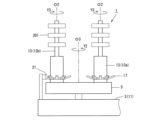
- FIG. 2 is a side view of the workpiece rotating device shown in FIG. 3 is an enlarged side view of the periphery of a gear and a kicker in the workpiece rotating device shown in FIG. 2.
- 3 is an enlarged plan view of the periphery of a gear and a kicker in the workpiece rotating device shown in FIG. 2.
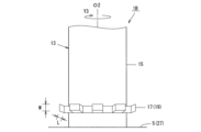
- 3 is an enlarged side view of the periphery of a gear in the workpiece rotating device shown in FIG. 2 .
- FIG. 6 is an enlarged side view of the periphery of a gear in a workpiece rotating device according to one non-limiting aspect of the present disclosure, and corresponds to FIG. 5 .
- FIG. 6 is an enlarged side view of the periphery of a gear in a workpiece rotating device according to one non-limiting aspect of the present disclosure, and corresponds to FIG. 5 .
- the workpiece rotating device 1 of one aspect of the present disclosure will be described in detail with reference to the drawings.
- the workpiece rotating device 1 may include any component member not shown in each of the drawings referred to.
- the dimensions of the components in each drawing do not faithfully represent the dimensions of the actual components and the dimensional ratios of each component.
- kickers and the like are omitted in FIG. 1.
- FIG. 2 a rotating table and the like that overlap with the revolution axis when viewed from the side are omitted.
- the workpiece rotating device 1 may be a device that rotates the workpiece 201 around a revolution axis O1 while rotating the workpiece 201 around a rotation axis O2 parallel to the revolution axis O1, as in a non-limiting example shown in Figures 1 and 2.
- the workpiece rotating device 1 may also be a device that rotates multiple workpieces 201.
- the workpiece 201 may also be referred to as a substrate.
- the workpiece 201 may be plate-shaped.
- the workpiece 201 may be in the shape of a rectangular plate.
- the shape of the workpiece 201 is not limited to a rectangular plate.
- the top surface of the workpiece 201 may be triangular, pentagonal, hexagonal, or circular.
- the workpiece 201 may be for a coated tool used in a cutting tool or the like.
- the workpiece 201 may also have a through hole.
- the through hole can function as a portion to which a fixing screw or a clamp member or the like is attached when the coated tool is held in a holder.
- the workpiece 201 is not limited to a specific size.
- the length of one side of the top surface may be set to approximately 3 to 20 mm.
- the height from the top surface to the bottom surface may be set to approximately 5 to 20 mm.
- the workpiece 201 is not limited to being plate-shaped.
- the workpiece 201 may be rod-shaped, etc.
- the material of the workpiece 201 may be, for example, a cemented carbide or a cermet.
- the composition of the cemented carbide may be, for example, WC-Co, WC-TiC-Co, and WC-TiC-TaC-Co.
- WC, TiC, and TaC may be hard particles, and Co may be a binder phase.
- the cermet may be a sintered composite material in which a ceramic component is combined with a metal.
- An example of a cermet is a titanium compound whose main component is TiC or TiN.
- the number of workpieces 201 to be rotated may be, for example, about 5 to 80.
- the number of workpieces 201 shown in the example may be the number per support pillar, which will be described later.
- the workpiece rotating device 1 can be used, for example, in a PVD processing device that forms a film on the surface of the workpiece 201 using the PVD method. Below, each component of the workpiece rotating device 1 will be explained in order, taking as an example the case where the workpiece rotating device 1 is used for a PVD processing device.
- the workpiece rotating device 1 may include a revolving table 3 and a rotating table 5, as shown in a non-limiting example in Figures 1 and 2.
- the revolution table 3 may be a member that revolves the workpiece 201 around the revolution axis O1.
- the central axis of the revolution table 3 may coincide with the revolution axis O1.
- the revolution table 3 is rotatable around the revolution axis O1.
- the arrow Y1 in FIG. 1 etc. may indicate the direction of rotation of the revolution table 3.
- the revolution table 3 may rotate in the opposite direction to the arrow Y1.
- a motor and gears may be used to rotate the revolution table 3.
- the driving force of the motor may be transmitted to the revolution table 3 via gears to rotate the revolution table 3. This is the same for other rotatable members such as the rotation table 5 described below.
- the revolution table 3 may be disk-shaped.
- the outer diameter of the revolution table 3 may be set to, for example, about 300 to 600 mm.
- the rotating table 5 may be a member that rotates the workpiece 201 on the revolution table 3 around a rotation axis O2 that is parallel to the revolution axis O1.
- the rotating table 5 is also rotatable around a central axis O3 of the rotating table 5.
- the central axis O3 of the rotating table 5 may be parallel to the revolution axis O1.
- the arrow Y2 in FIG. 1 etc. may indicate the rotation direction of the rotating table 5.
- the rotating table 5 may rotate in the opposite direction to the arrow Y2.
- the multiple rotation tables 5 may be located on the outer periphery of the revolution axis O1 on the upper surface 11 of the revolution table 3, as in the non-limiting example shown in FIG. 1.
- the multiple rotation tables 5 may be located at equal intervals in the circumferential direction of the revolution axis O1.
- the number of rotation tables 5 may be, for example, about 2 to 10.
- the rotating table 5 may have a support 13, as in the non-limiting example shown in FIG. 2.
- the support 13 is capable of holding the workpiece 201. If the workpiece 201 has the above-mentioned through hole, the support 13 may be inserted into the through hole to hold the workpiece 201 on the support 13. Also, if the workpiece 201 is rod-shaped, the workpiece 201 may be held on the support 13 using a jig or the like.
- the support pillar 13 may be located between the main body 7 and the top plate 9.
- the support pillar 13 may also be cylindrical.
- the diameter of the support pillar 13 may be set to about 1 to 10 mm.
- the length of the support pillar 13 may be set to about 200 to 700 mm.
- the multiple pillars 13 may be positioned at equal intervals in the circumferential direction of the central axis O3.
- the number of pillars 13 on one rotating table 5 may be, for example, about 2 to 20.
- the rotation axis O2 may be located on the outer periphery side of the rotation table 5 relative to the central axis O3. Furthermore, the support pillar 13 may extend along the rotation axis O2. The support pillar 13 is rotatable around the rotation axis O2.
- the main body 7 and the top plate 9 may have a through hole through which the end of the support 13 can be inserted, or a recess into which the end of the support 13 can be inserted, and the end of the support 13 may be positioned in this through hole or recess to make the support 13 rotatable.
- the arrow Y3 in FIG. 2 etc. may indicate the direction of rotation of the support 13. Note that the support 13 may rotate in the opposite direction to the arrow Y3.
- the support 13 may have an outer peripheral surface 15 and a gear 17, as shown in a non-limiting example in FIG. 5.
- the gear 17 may be located on the outer peripheral surface 15.
- the gear 17 may also be attached to the outer peripheral surface 15.
- the gear 17 may be attached to the outer peripheral surface 15 by welding.
- the gear 17 may be formed integrally with the outer peripheral surface 15.
- the gear 17 may be located below the workpiece 201.
- the gear 17 may be located on the lower end side of the support 13.
- the teeth 19 of the gear 17 may be positioned along the circumferential direction of the rotation axis O2.
- the teeth 19 may be portions that correspond to protruding portions of the gear 17.
- the number of teeth 19 on one gear 17 may be, for example, about 6 to 12.
- the workpiece rotating device 1 may further include a kicker 21, as shown in the non-limiting example in Figures 3 and 4.
- the kicker 21 may be located at a location other than the rotation table 5.
- the kicker 21 may be located on the upper surface 11 of the revolution table 3.
- the kicker 21 may be attached to a columnar member or the like located on the upper surface 11 of the revolution table 3.
- the kicker 21 may be a plate-shaped member whose tip 23 meshes with the gear 17, as shown in a non-limiting example in FIG. 4. Therefore, the kicker 21 may be located at a location other than the rotating table 5, where the tip 23 meshes with the gear 17.
- the kicker 21 can function as a member that rotates the support 13 around the rotation axis O2. More specifically, as the turntable 5 rotates, the tip 23 of the kicker 21 meshes with the gear 17. When the turntable 5 rotates further from this state, the tip 23 of the kicker 21 is released from the gear 17. At this time, the external force applied to the gear 17 can cause the support 13 to rotate around the rotation axis O2. Rotating the support 13 in this manner to rotate the workpiece 201 enables more uniform film formation.
- the support 13 may also rotate in the opposite direction to the turntable 5.
- the support 13 may have a first portion 13a where the gear 17 is located, and a second portion 13b where the workpiece 201 is located, as in the non-limiting example shown in FIG. 3.
- the diameter of the first portion 13a may be larger than the diameter of the second portion 13b. In these cases, the first portion 13a, which is likely to be subjected to a relatively large external force due to the location of the gear 17, has a relatively large diameter, making it easier to maintain the strength of the support 13.
- the kicker 21 may have a tip 23 that is inclined relative to the base 25, as shown in a non-limiting example in FIG. 4. In this case, the tip 23 is more likely to mesh with the gear 17.
- the kicker 21 may be a leaf spring. In this case, it is easy to rotate the support 13 stably. Therefore, it is easy to rotate the workpiece 201 stably.
- the total tooth depth L of the gear 17 may be the maximum length of the teeth 19 extending in a direction away from the rotation axis O2 when viewed from a direction perpendicular to the rotation axis O2, as in a non-limiting example shown in FIG. 5.
- the tooth width W of the gear 17 may be the thickness of the teeth 19 when viewed from a direction perpendicular to the rotation axis O2. "When viewed from a direction perpendicular to the rotation axis O2" may be rephrased as a side view.
- the total tooth depth L and the tooth width W are not limited to a specific size. For example, the total tooth depth L may be set to 3 mm or more. The upper limit of the total tooth depth L may be set to 9 mm.
- the tooth width W may be set to 12 mm or less.
- the lower limit of the tooth width W may be set to 1 mm.
- the gear 17 may have a total tooth depth L greater than the tooth width W. In this case, rotation errors of the support 13 are less likely to occur.
- the teeth 19 of the gear 17 may be inclined away from the top surface 27 of the rotating table 5 as they move away from the outer circumferential surface 15, as in the non-limiting example shown in FIG. 5.
- Such a gear 17 may also be called a petal-shaped gear.
- the kicker 21 is more likely to be released smoothly from the gear 17.
- the top surface 27 of the rotating table 5 may be the top surface of the main body 7.
- the inclination angle ⁇ of the teeth 19 relative to the reference line S1 perpendicular to the rotation axis O2 may be set to approximately 5 to 80°. In this case, the kicker 21 is more likely to be released smoothly from the gear 17. If the inclination angle ⁇ is 10 to 45°, the kicker 21 is more likely to be released smoothly from the gear 17. If the inclination angle ⁇ is 15 to 35°, the kicker 21 is even more likely to be released smoothly from the gear 17.
- workpiece rotating device 1A will be described as another non-limiting aspect of the present disclosure.
- workpiece rotating device 1A the differences between workpiece rotating device 1A and workpiece rotating device 1 will be mainly described, and detailed descriptions of the same configuration as workpiece rotating device 1 may be omitted. Therefore, the description of workpiece rotating device 1 may be used to understand the configuration of workpiece rotating device 1A. This also applies to workpiece rotating device 1B, which will be described later.
- the total tooth depth L of the gear 17 may be the same as the tooth width W.
- the tooth depth L is the same as the tooth width W, it is easier to maintain the strength of the teeth 19. Therefore, even when a large external force is applied to the gear 17, the support 13 is likely to rotate stably.
- the total tooth depth L of the gear 17 may be smaller than the tooth width W. In this case, it is easier to maintain the strength of the teeth 19. Therefore, even if a large external force is applied to the gear 17, the support 13 is likely to rotate stably.
- PVD processing apparatus 101 of the present disclosure a non-limiting example of the PVD processing apparatus 101 of the present disclosure will be described using the case where the above-mentioned workpiece rotating apparatus 1 is provided.
- the PVD processing apparatus 101 may include a workpiece rotation device 1, a target 103, and a vacuum chamber 105, as shown in a non-limiting example in FIG. 1.
- a workpiece rotation device 1 When the PVD processing apparatus 101 includes a workpiece rotation device 1, uniform film formation is possible.
- the PVD processing device 101 may be a device that uses a PVD method to form a coating layer on the surface of the workpiece 201 housed inside the vacuum chamber 105.
- Examples of the PVD method include an ion plating method and a sputtering method.
- the target 103 may be located outside the revolution table 3.
- the target 103 may also be located radially outside the revolution table 3.
- the target 103 may be located on the inner wall surface of the vacuum chamber 105.
- the target 103 may be formed from a film-forming material that is the raw material for the coating layer.
- the target 103 may also be called an evaporation source or a deposition source.
- the target 103 may be in the form of a plate.
- the multiple targets 103 may be formed from different types of deposition materials, or may be formed from the same type of deposition material.
- the multiple targets 103 may be positioned at intervals in the direction along the revolution axis O1.
- the multiple targets 103 may be positioned at intervals along the circumferential direction of the revolution table 3. For example, when there are two targets 103, the two targets 103 may be positioned so as to face each other with the revolution table 3 in between. When there are multiple targets 103, the number of targets 103 may be, for example, about 2 to 16.
- the vacuum chamber 105 may house the workpiece rotating device 1 and the target 103 inside.
- the vacuum chamber 105 is also capable of reducing the pressure inside.
- an exhaust pipe may be connected to the vacuum chamber 105, and a vacuum pump or the like may be connected to the exhaust pipe, and the inside may be evacuated to a vacuum or extremely low pressure.
- a gas supply pipe may be connected to the vacuum chamber 105, and an inert gas or reactive gas or the like may be supplied to the inside of the vacuum chamber 105.
- the method for producing a coated tool may be a method for forming a coating layer on the surface of the workpiece 201 using the PVD processing device 101 to obtain a coated tool.
- the PVD processing device 101 is used in the method for producing a coated tool, uniform film formation is possible, so that the quality of the obtained coated tool is less likely to vary.
- the coating layer formed on the surface of the workpiece 201 may have a composition such as titanium carbide (TiC), titanium nitride (TiN), titanium carbonitride (TiCN), and alumina (Al 2 O 3 ).
- the coating layer is not limited to a specific thickness.
- the average thickness of the coating layer may be set to about 0.1 to 10 ⁇ m.
- the thickness of the coating layer may be measured by cross-sectional observation using an electron microscope.
- the thickness may be measured at 10 or more measurement points at any position on the coating layer, and the average value may be calculated.
- electron microscopes include a scanning electron microscope (SEM) and a transmission electron microscope (TEM).
- the obtained coated tool can be used as a cutting tool, etc.
- the coated tool can also be used for purposes other than cutting tools. Examples of other uses include wear-resistant parts such as sliding parts or dies, tools such as drilling tools and blades, and impact-resistant parts.
- the teeth 19 of the gear 17 are inclined so as to move away from the upper surface 27 of the rotating table 5 as they move away from the outer peripheral surface 15, but the teeth 19 of the gear 17 may also be inclined so as to move closer to the upper surface 27 of the rotating table 5 as they move away from the outer peripheral surface 15.
- the above-mentioned PVD processing apparatus 101 is equipped with a workpiece rotating device 1, but is not limited to this form.
- the PVD processing apparatus 101 may be equipped with a workpiece rotating device 1A or a workpiece rotating device 1B instead of the workpiece rotating device 1.
Landscapes
- Chemical & Material Sciences (AREA)
- Chemical Kinetics & Catalysis (AREA)
- Engineering & Computer Science (AREA)
- Materials Engineering (AREA)
- Mechanical Engineering (AREA)
- Metallurgy (AREA)
- Organic Chemistry (AREA)
- Physical Vapour Deposition (AREA)
Priority Applications (3)
| Application Number | Priority Date | Filing Date | Title |
|---|---|---|---|
| CN202380092624.8A CN120826492A (zh) | 2023-03-20 | 2023-03-20 | 工件旋转装置、pvd处理装置及涂层刀具的制造方法 |
| JP2025507967A JPWO2024194994A1 (https=) | 2023-03-20 | 2023-03-20 | |
| PCT/JP2023/010924 WO2024194994A1 (ja) | 2023-03-20 | 2023-03-20 | ワーク回転装置、pvd処理装置および被覆工具の製造方法 |
Applications Claiming Priority (1)
| Application Number | Priority Date | Filing Date | Title |
|---|---|---|---|
| PCT/JP2023/010924 WO2024194994A1 (ja) | 2023-03-20 | 2023-03-20 | ワーク回転装置、pvd処理装置および被覆工具の製造方法 |
Publications (1)
| Publication Number | Publication Date |
|---|---|
| WO2024194994A1 true WO2024194994A1 (ja) | 2024-09-26 |
Family
ID=92841151
Family Applications (1)
| Application Number | Title | Priority Date | Filing Date |
|---|---|---|---|
| PCT/JP2023/010924 Ceased WO2024194994A1 (ja) | 2023-03-20 | 2023-03-20 | ワーク回転装置、pvd処理装置および被覆工具の製造方法 |
Country Status (3)
| Country | Link |
|---|---|
| JP (1) | JPWO2024194994A1 (https=) |
| CN (1) | CN120826492A (https=) |
| WO (1) | WO2024194994A1 (https=) |
Citations (4)
| Publication number | Priority date | Publication date | Assignee | Title |
|---|---|---|---|---|
| JPH04110749U (ja) * | 1991-03-04 | 1992-09-25 | 株式会社神戸製鋼所 | アークイオンプレーテイング装置における回転テーブル |
| JP2009280881A (ja) * | 2008-05-26 | 2009-12-03 | Nissin Electric Co Ltd | 膜形成対象物品支持装置及び膜形成装置 |
| JP2015134950A (ja) * | 2014-01-17 | 2015-07-27 | 株式会社デンソー | 成膜装置 |
| JP2018135558A (ja) * | 2017-02-21 | 2018-08-30 | 株式会社神戸製鋼所 | ワーク回転装置およびそれを備えた成膜装置 |
-
2023
- 2023-03-20 CN CN202380092624.8A patent/CN120826492A/zh active Pending
- 2023-03-20 JP JP2025507967A patent/JPWO2024194994A1/ja active Pending
- 2023-03-20 WO PCT/JP2023/010924 patent/WO2024194994A1/ja not_active Ceased
Patent Citations (4)
| Publication number | Priority date | Publication date | Assignee | Title |
|---|---|---|---|---|
| JPH04110749U (ja) * | 1991-03-04 | 1992-09-25 | 株式会社神戸製鋼所 | アークイオンプレーテイング装置における回転テーブル |
| JP2009280881A (ja) * | 2008-05-26 | 2009-12-03 | Nissin Electric Co Ltd | 膜形成対象物品支持装置及び膜形成装置 |
| JP2015134950A (ja) * | 2014-01-17 | 2015-07-27 | 株式会社デンソー | 成膜装置 |
| JP2018135558A (ja) * | 2017-02-21 | 2018-08-30 | 株式会社神戸製鋼所 | ワーク回転装置およびそれを備えた成膜装置 |
Also Published As
| Publication number | Publication date |
|---|---|
| JPWO2024194994A1 (https=) | 2024-09-26 |
| CN120826492A (zh) | 2025-10-21 |
Similar Documents
| Publication | Publication Date | Title |
|---|---|---|
| CN105051247B (zh) | Pvd处理装置以及pvd处理方法 | |
| CN104884199A (zh) | 表面包覆切削工具 | |
| JP7552986B1 (ja) | 切削工具 | |
| WO2011135810A1 (ja) | 成膜装置 | |
| WO2014076947A1 (ja) | 成膜装置 | |
| CN108998758A (zh) | 具有涂层的钻头 | |
| CN110268093A (zh) | 成膜装置以及成膜物的制造方法 | |
| WO2015064241A1 (ja) | 表面被覆窒化硼素焼結体工具 | |
| WO2018070195A1 (ja) | 表面被覆切削工具 | |
| JP2015110256A (ja) | 表面被覆切削工具 | |
| WO2024194994A1 (ja) | ワーク回転装置、pvd処理装置および被覆工具の製造方法 | |
| KR20190136771A (ko) | 연동 회전하는 회전기를 가지는 증착장치 | |
| US10471523B2 (en) | Rotating tool | |
| WO2024194986A1 (ja) | 治具、工具回転装置、pvd処理装置および被覆工具の製造方法 | |
| WO2024194995A1 (ja) | ワーク回転装置、pvd処理装置および被覆工具の製造方法 | |
| WO2024209529A1 (ja) | コーティング方法 | |
| JP4782222B2 (ja) | 穴明け工具用非晶質炭素皮膜及び穴明け工具 | |
| WO2025004125A1 (ja) | 成膜方法 | |
| JP6845877B2 (ja) | ワーク保持部回転ユニット及び真空処理装置 | |
| US20250339901A1 (en) | Coated tool and cutting tool | |
| JP4106934B2 (ja) | 工具の成膜装置および成膜方法 | |
| JP2020132906A (ja) | 成膜品の製造方法及びスパッタリング装置 | |
| JP7850815B2 (ja) | 被覆工具および切削工具 | |
| WO2025206384A1 (ja) | 被覆工具、切削工具、および切削加工物の製造方法 | |
| KR20110042190A (ko) | 물리 기상 증착 장치 및 방법 |
Legal Events
| Date | Code | Title | Description |
|---|---|---|---|
| 121 | Ep: the epo has been informed by wipo that ep was designated in this application |
Ref document number: 23928577 Country of ref document: EP Kind code of ref document: A1 |
|
| ENP | Entry into the national phase |
Ref document number: 2025507967 Country of ref document: JP Kind code of ref document: A |
|
| WWE | Wipo information: entry into national phase |
Ref document number: 2025507967 Country of ref document: JP |
|
| WWE | Wipo information: entry into national phase |
Ref document number: 202380092624.8 Country of ref document: CN |
|
| NENP | Non-entry into the national phase |
Ref country code: DE |
|
| WWP | Wipo information: published in national office |
Ref document number: 202380092624.8 Country of ref document: CN |
|
| 122 | Ep: pct application non-entry in european phase |
Ref document number: 23928577 Country of ref document: EP Kind code of ref document: A1 |