WO2024190239A1 - シリンダ装置 - Google Patents
シリンダ装置 Download PDFInfo
- Publication number
- WO2024190239A1 WO2024190239A1 PCT/JP2024/004933 JP2024004933W WO2024190239A1 WO 2024190239 A1 WO2024190239 A1 WO 2024190239A1 JP 2024004933 W JP2024004933 W JP 2024004933W WO 2024190239 A1 WO2024190239 A1 WO 2024190239A1
- Authority
- WO
- WIPO (PCT)
- Prior art keywords
- piston
- cylinder
- piston body
- stopper portion
- piston ring
- Prior art date
- Legal status (The legal status is an assumption and is not a legal conclusion. Google has not performed a legal analysis and makes no representation as to the accuracy of the status listed.)
- Ceased
Links
Images

Classifications
-
- F—MECHANICAL ENGINEERING; LIGHTING; HEATING; WEAPONS; BLASTING
- F16—ENGINEERING ELEMENTS AND UNITS; GENERAL MEASURES FOR PRODUCING AND MAINTAINING EFFECTIVE FUNCTIONING OF MACHINES OR INSTALLATIONS; THERMAL INSULATION IN GENERAL
- F16F—SPRINGS; SHOCK-ABSORBERS; MEANS FOR DAMPING VIBRATION
- F16F9/00—Springs, vibration-dampers, shock-absorbers, or similarly-constructed movement-dampers using a fluid or the equivalent as damping medium
- F16F9/32—Details
- F16F9/3207—Constructional features
- F16F9/3235—Constructional features of cylinders
-
- F—MECHANICAL ENGINEERING; LIGHTING; HEATING; WEAPONS; BLASTING
- F16—ENGINEERING ELEMENTS AND UNITS; GENERAL MEASURES FOR PRODUCING AND MAINTAINING EFFECTIVE FUNCTIONING OF MACHINES OR INSTALLATIONS; THERMAL INSULATION IN GENERAL
- F16F—SPRINGS; SHOCK-ABSORBERS; MEANS FOR DAMPING VIBRATION
- F16F9/00—Springs, vibration-dampers, shock-absorbers, or similarly-constructed movement-dampers using a fluid or the equivalent as damping medium
- F16F9/32—Details
- F16F9/58—Stroke limiting stops, e.g. arranged on the piston rod outside the cylinder
- F16F9/585—Stroke limiting stops, e.g. arranged on the piston rod outside the cylinder within the cylinder, in contact with working fluid
-
- F—MECHANICAL ENGINEERING; LIGHTING; HEATING; WEAPONS; BLASTING
- F16—ENGINEERING ELEMENTS AND UNITS; GENERAL MEASURES FOR PRODUCING AND MAINTAINING EFFECTIVE FUNCTIONING OF MACHINES OR INSTALLATIONS; THERMAL INSULATION IN GENERAL
- F16F—SPRINGS; SHOCK-ABSORBERS; MEANS FOR DAMPING VIBRATION
- F16F9/00—Springs, vibration-dampers, shock-absorbers, or similarly-constructed movement-dampers using a fluid or the equivalent as damping medium
- F16F9/10—Springs, vibration-dampers, shock-absorbers, or similarly-constructed movement-dampers using a fluid or the equivalent as damping medium using liquid only; using a fluid of which the nature is immaterial
- F16F9/14—Devices with one or more members, e.g. pistons, vanes, moving to and fro in chambers and using throttling effect
- F16F9/16—Devices with one or more members, e.g. pistons, vanes, moving to and fro in chambers and using throttling effect involving only straight-line movement of the effective parts
- F16F9/18—Devices with one or more members, e.g. pistons, vanes, moving to and fro in chambers and using throttling effect involving only straight-line movement of the effective parts with a closed cylinder and a piston separating two or more working spaces therein
- F16F9/19—Devices with one or more members, e.g. pistons, vanes, moving to and fro in chambers and using throttling effect involving only straight-line movement of the effective parts with a closed cylinder and a piston separating two or more working spaces therein with a single cylinder and of single-tube type
Definitions
- the present invention relates to a cylinder device.
- An example of a conventional cylinder device is a shock absorber that is installed between the body and axle of a vehicle and suppresses vibration of the body and wheels by exerting a damping force when the axle expands or contracts.
- Such a shock absorber comprises a cylinder, a rod inserted into the cylinder so as to be movable in the axial direction, a piston body inserted into the cylinder so as to be movable in the axial direction and connected to the rod, and a piston ring attached to the outer periphery of the piston body and in sliding contact with the inner periphery of the cylinder, dividing the inside of the cylinder into an extension side chamber and a compression side chamber, and a damping passage provided in the piston body that communicates between the extension side chamber and the compression side chamber and provides resistance to the flow of liquid passing through.
- the rod only needs to be long enough to ensure the stroke amount required for the shock absorber to be installed in the vehicle, so the length of the rod may be made shorter than the length of the cylinder to reduce the shock absorber's weight.
- shock absorber for example, when transporting the shock absorber, an operator may push the rod into the cylinder to shorten the overall length of the shock absorber. However, if an operator accidentally pushes the entire rod into the cylinder when pushing the rod into the cylinder, the rod may sink into the cylinder, causing the liquid in the cylinder to leak out.
- the stopper may interfere with the seal ring that seals the outer circumference of the rod, which may also cause the liquid to leak out.
- a stopper is provided on the inner circumference of the cylinder that the piston comes into contact with to restrict the movement of the rod before the rod slides into the cylinder when the operator pushes the rod into the cylinder, thereby preventing the rod from sliding into the cylinder.
- This stopper portion is formed by crimping the cylinder from the outside, giving it an arc-shaped cross section. The end of the piston abuts against any part of the stopper portion between the tip and the central apex, preventing the rod from slipping into the cylinder.
- the stopper portion is formed with an arc-shaped cross section
- the end of the piston ring facing the stopper may come into contact with the part of the stopper portion that abuts against the piston before the piston body of the piston abuts against the stopper portion.
- This can cause the piston ring to ride up onto the tip side of the stopper portion and become caught between the piston body and the stopper portion, which can lead to problems such as deterioration of the piston ring or the piston becoming stuck in the cylinder and unable to move.
- the present invention aims to provide a cylinder device that does not have a risk of the piston ring becoming caught between the piston body and the stopper portion, even if a stopper portion is provided on the inner circumference of the cylinder by crimping the cylinder from the outer circumference side.
- the cylinder device of the present invention includes a piston having a piston body connected to a rod movably inserted into the cylinder in the axial direction and movably inserted into the cylinder in the axial direction, and a piston ring attached to the outer periphery of the piston body and slidingly contacting the inner periphery of the cylinder, the cylinder is formed by crimping from the outer periphery side and protruding toward the inner periphery side of the cylinder, and has a stopper portion that abuts against the outer periphery end of one end of the piston body when the piston moves in one direction within the cylinder to the stroke end, and is characterized in that the axial distance between the axial piston side end of the stopper portion and the part of the stopper portion with which the piston body abuts is shorter than the axial distance between the end of the sliding surface of the piston ring that slides against the inner periphery of the cylinder on the stopper portion side
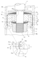
- FIG. 1 is a cross-sectional view of a shock absorber according to the present embodiment.
- FIG. 2 is an enlarged cross-sectional view showing a portion of the shock absorber according to the present embodiment.
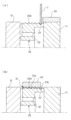
- Fig. 3(A) is a diagram for explaining a processing procedure for mounting a piston ring on the outer periphery of a piston body in the shock absorber of this embodiment.
- Fig. 3(B) is a diagram for explaining a state in which a base material is pressed into an inner periphery of a die in processing for mounting a piston ring on the outer periphery of a piston body in the shock absorber of this embodiment.
- shock absorber D as a cylinder device of the present invention will be described with reference to the drawings.
- the same reference numerals used throughout the drawings indicate the same parts.
- the top and bottom of shock absorber D when installed on a vehicle will simply be referred to as “upper” and “lower”.
- the shock absorber D in this embodiment includes a cylinder 1, a rod 2 inserted into the cylinder 1 so as to be movable in the axial direction, a piston 3 having a piston body 30 inserted into the cylinder 1 so as to be movable in the axial direction and connected to the rod 2, and a piston ring 31 attached to the outer periphery of the piston body 30 and in sliding contact with the inner periphery of the cylinder 1, and the cylinder 1 is formed by crimping from the outer periphery side and has a stopper portion 10 that protrudes toward the inner periphery of the cylinder 1 and abuts against one end of the piston body 30 when the piston 3 moves downward inside the cylinder 1 to the stroke end.
- the shock absorber D is an upright type in which the rod 2 is connected to the vehicle body side and the cylinder 1 is connected to the axle side, but the shock absorber D may be an inverted type in which the cylinder 1 is connected to the vehicle body side and the rod 2 is connected to the axle side.
- a free piston 7 is provided at the bottom of the cylinder 1 in FIG. 1, sliding against the inner circumference of the cylinder 1 to divide the cylinder 1 into a liquid chamber R and an air chamber G.
- the liquid chamber R is divided into an extension side chamber R1 and a compression side chamber R2 by a piston 3 slidably inserted into the cylinder 1.
- the extension side chamber R1 and the compression side chamber R2 are filled with a liquid such as hydraulic oil
- the air chamber G is filled with an inert gas such as nitrogen.
- the liquid filled in the extension side chamber R1 and the compression side chamber R2 can be liquids other than hydraulic oil, such as water or an aqueous solution.
- the air chamber G may also be filled with a gas other than an inert gas.
- the lower end of the cylinder 1 in FIG. 1 is closed by a bottom cap 4, and an annular rod guide 5 that supports the rod 2 so that it can slide freely is attached to the upper end in FIG. 1.
- a seal member 6 that slides against the outer periphery of the rod 2 is attached to the upper end of the cylinder 1 in FIG. 1, above the rod guide 5 in FIG. 1. This seal member 6 seals the outer periphery of the rod 2 to prevent leakage of liquid inside the cylinder 1.
- the rod 2 has a main body 2a that slides against the seal member 6 and moves in and out of the cylinder 1, and a connecting part 2b above the main body 2a that has a smaller outer diameter than the main body 2a and can be connected to a vehicle, etc.
- the piston 3 is composed of an annular piston body 30 and a cylindrical piston ring 31 made of synthetic resin and attached to the outer periphery of the piston body 30.
- the piston body 30 includes an annular disk portion 32 with a mounting hole 30a formed in the center, an annular skirt portion 33 extending axially downward in FIG. 1 from the outer periphery of the disk portion 32, a plurality of expansion side ports 34 and a plurality of compression side ports 35 that penetrate the disk portion 32 in the axial direction, an annular expansion side valve seat 36 provided inside the skirt portion 33 at the lower end of the disk portion 32 in FIG. 1, and a petal-shaped compression side valve seat 37 provided at the upper end of the disk portion 32 in FIG. 1.
- the compression side port 35 has an inlet end that opens to the outside of the expansion side valve seat 36 at the lower end of the disk portion 32 in FIG. 1, and an outlet end that opens from an independent opening window 37a surrounded by the compression side valve seat 37 at the upper end of the disk portion 32 in FIG. 1, connecting the expansion side chamber R1 and the compression side chamber R2.
- the inlet end of the expansion side port 34 opens at a location not surrounded by the compression side valve seat 37 at the upper end of the disk portion 32 in FIG. 1, and the outlet end opens inside the expansion side valve seat 36 at the lower end of the disk portion 32 in FIG. 1, connecting the expansion side chamber R1 and the compression side chamber R2.
- annular compression side leaf valve V1 that seats on the compression side valve seat 37 is stacked at the upper end of the piston 3 in FIG. 1 facing the compression side chamber R1
- annular expansion side leaf valve V2 that seats on the expansion side valve seat 36 is stacked at the lower end of the piston 3 in FIG. 1 facing the compression side chamber R2.
- the compression side leaf valve V1 When the compression side leaf valve V1 is seated on the compression side valve seat 37, it closes the compression side port 35, and when the outer circumferential side is deflected, it opens the compression side port 35, so that it can open and close the compression side port 35.
- the extension side leaf valve V2 When the extension side leaf valve V2 is seated on the extension side valve seat 36, it closes the extension side port 34, and when the outer circumferential side is deflected, it opens the extension side port 34, so that it can open and close the extension side port 34.
- the piston ring mounting portion 30b which has multiple annular grooves along the circumferential direction, is provided on the outer periphery of the disk portion 32 and skirt portion 33 of the piston body 30.
- the piston ring 31 is heated and pressed against the piston ring mounting portion 30b, the inner periphery of the piston ring 31 is deformed into a shape that matches the piston ring mounting portion 30b, and the piston ring 31 is integrated with the piston body 30.
- the operation of the shock absorber D of this embodiment will be described in detail.
- the pressure of the compression side chamber R2 which is compressed and the pressure increases, presses the expansion side leaf valve V2 toward the piston 3, closing the expansion side port 34.
- the compression side leaf valve V1 which receives the pressure of the compression side chamber R2 through the compression side port 35, bends and leaves the compression side valve seat 37, opening the compression side port 35.
- the compression side leaf valve V1 provides resistance to the flow of liquid that passes through the compression side port 35 and moves from the compression side chamber R2 to the expansion side chamber R1, so the shock absorber D exerts a compression side damping force that prevents its own contraction.
- shock absorber D expands, the pressure in the compression-side chamber R1, which is compressed and pressurized, presses the compression-side leaf valve V1 toward the piston 3, closing the compression-side port 35, while the compression-side leaf valve V2, which receives the pressure of the compression-side chamber R1 through the expansion-side port 34, bends and leaves the expansion-side valve seat 36, opening the expansion-side port 34.
- the expansion-side leaf valve V2 provides resistance to the flow of liquid that passes through the expansion-side port 34 and moves from the expansion-side chamber R1 to the compression-side chamber R2, so that shock absorber D exerts an expansion-side damping force that hinders its own expansion.
- the shock absorber D in this embodiment is a single-cylinder shock absorber, but it may also be configured as a so-called double-cylinder shock absorber in which a base valve is provided at the bottom end of the cylinder 1 and a reservoir is provided outside the cylinder.
- the stopper portion 10 is formed in an annular shape by crimping the cylinder 1 from the outer periphery so as to protrude toward the inner periphery of the cylinder 1. Then, as shown in FIG. 2, when the piston 3 moves to the lower stroke end inside the cylinder 1, the outer periphery of the lower end of the piston body 30 abuts against the stopper portion 10, restricting the downward axial movement of the piston 3.
- the stopper portion 10 is provided at a position below the lower limit position, which is the maximum stroke position on the contraction side of the shock absorber D, within the stroke range of the piston 3 required for the shock absorber D mounted on the vehicle.
- the stopper portion 10 When the stopper portion 10 is provided at the lowest position of the piston 3, the stopper portion 10 allows the stroke of the piston 3 required for the shock absorber D mounted on the vehicle, while the outer peripheral end of the lower end side of the piston body 30 abuts against the stopper portion 10 when the shock absorber D is fully contracted, thereby preventing the shock absorber D from contracting any further.
- the stopper portion 10 When the stopper portion 10 is provided below the lowest position of the piston 3, the stopper portion 10 allows the stroke of the piston 3 required for the shock absorber D mounted on the vehicle, while not interfering with the piston 3 when the shock absorber D expands and contracts within the required range to exert a damping force.
- the stopper portion 10 is located outside the stroke range of the free piston 7, so it does not interfere with the free piston 7.
- shock absorber D is configured as a so-called twin-cylinder shock absorber in which a base valve is provided at the lower end of cylinder 1 and a reservoir is provided outside the cylinder, stopper portion 10 is provided above the base valve of cylinder 1, so that stopper portion 10 can prevent piston 3 from contacting the base valve.
- the stopper portion 10 is also located at a position where it abuts against the outer peripheral edge of the lower end of the piston body 30 before the entire body portion 2a of the rod 2 enters the cylinder 1 when the shock absorber D is compressed and the rod 2 is pushed into the cylinder 1. Therefore, in this embodiment, the outer peripheral edge of the lower end of the piston 3 abuts against the stopper portion 10 before the body portion 2a of the rod 2 slides into the cylinder 1, restricting the downward axial movement of the piston 3, and therefore preventing the body portion 2a of the rod 2 from sliding into the cylinder 1.
- the upper end outer periphery of the main body 2a of the rod 2 may be provided with a large diameter portion made of a collar or the like for attaching a bump cushion or the like to the upper end outer periphery of the rod 2.
- the large diameter portion of the rod 2 may come into contact with the seal member 6 arranged above the rod guide 5 and damage the seal member 6.
- the stopper portion 10 is formed into an arc-shaped cross section by crimping the cylinder 1 from the outer periphery. Then, when the piston 3 moves to the lower stroke end inside the cylinder 1, the outer periphery on the lower end side of the piston body 30 abuts against a part (abutment part 10a) in the middle between the upper end 10b and the central apex of the stopper portion 10, restricting the downward movement of the piston 3.
- the position of the abutment part 10a varies depending on the radius of curvature of the stopper portion 10 and the shape of the outer periphery on the lower end side of the piston body 30, it is not limited to the middle between the upper end 10b and the central apex of the stopper portion 10, and any part between the upper end 10b and the central apex of the stopper portion 10 becomes the abutment part 10a.
- the axial distance W between the upper end 10b (the end on the piston 3 side) of the stopper portion 10 and the abutment portion 10a, which is the portion of the stopper portion 10 that abuts against the piston body 30, is set to be shorter than the axial distance L between the lower end 31a1 (the end on the stopper portion 10 side) of the sliding surface 31a that slides against the inner circumference of the cylinder 1 of the piston ring 31 and the outer circumferential end on the lower end side of the piston body 30 (the portion that abuts against the abutment portion 10a of the stopper portion 10).
- the axial distance W between the upper end 10b of the stopper portion 10 and the abutment portion 10a refers to the distance between an extension line extending radially from the upper end 10b of the stopper portion 10 and an extension line extending radially from the abutment portion 10a of the stopper portion 10.
- the axial distance L between the lower end 31a1 of the sliding surface 31a of the piston ring 31 that slides against the inner circumference of the cylinder 1 and the outer circumferential edge of the lower end of the piston body 30 refers to the distance between an extension line extending radially from the lower end 31a1 of the sliding surface 31a of the piston ring 31 and an extension line extending radially from the outer circumferential edge of the lower end of the piston body 30.
- the stopper portion 10 is formed by roll crimping the cylinder 1 from the outer periphery, but the stopper portion may be formed by a crimping method other than roll crimping, for example, multi-point crimping, in which the cylinder 1 is crimped at multiple points in the circumferential direction.
- a crimping method other than roll crimping for example, multi-point crimping, in which the cylinder 1 is crimped at multiple points in the circumferential direction.
- multi-point crimping at least two stopper portions need to be provided.
- the stopper portion 10 is formed by multi-point crimping, if the axial position of the crimped points is misaligned in the circumferential direction, when the outer peripheral edge of the lower end side of the piston body 30 abuts against the stopper portion, there will be some places where the stopper portion abuts against the piston body 30 and some places where it does not abut.
- the stopper portion 10 is formed by roll crimping as in this embodiment, the axial position of the stopper portion 10 is aligned in the circumferential direction, so that when the outer peripheral edge of the lower end side of the piston body 30 abuts against the stopper portion 10, the entire stopper portion 10 can support the piston body 30. Therefore, when the stopper portion 10 is formed by roll crimping, the load-bearing capacity of the stopper portion 10 is improved.
- the piston ring 31 is attached to the outer periphery of the piston body 30 by fitting a disk-shaped base material J made of synthetic resin into an annular groove located at one end of a piston ring attachment portion 30b provided on the outer periphery of the piston body 30 as shown in FIG. 3(A), and then forcing the piston body 30 into the cylindrical die 20 from one end as shown in FIG. 3(B).
- the cylindrical die 20 installed on the fixed jig 11 abutting against one end of the piston body 30 is moved toward the other end of the piston body 30, and the base material J, which has become heated and easily deformed, is pushed into the cylindrical die 20 together with the base material J from one end of the piston body 30.
- the inner diameter of the die 20 is larger than the outer diameter of the piston body 30, but the gap between the die 20 and the piston body 30 is narrower than the thickness of the base material J.
- the base material J is heated and softened, as the piston body 30 penetrates into the die 20 more, it is squeezed by the die 20 and is pressed against the piston ring mounting portion 30b from the outside by the die 20. The base material J then deforms so that its inner circumference fits the outer shape of the piston ring mounting portion 30b and enters the annular groove, and is firmly fixed to the piston body 30.
- the piston ring 31 mounted on the outer periphery of the piston body 30 has a cylindrical sliding surface 31a that slides against the inner periphery of the cylinder 1, and an inwardly inclined portion 31b that is connected to the lower end 31a1 of the sliding surface 31a.
- the inclined portion 31b of the piston ring 31 does not slide against the inner circumference of the cylinder 1, so when the piston 3 is connected to the rod 2 so that the inclined portion 31b faces downward (toward the stopper portion 10) as shown in FIG. 2, the axial distance L between the lower end 31a1 of the sliding surface 31a of the piston ring 31 and the outer circumferential end of the lower end of the piston body 30 can be made longer by the axial length of the inclined portion 31b.
- the piston ring 31 may be attached to the outer periphery of the piston 3 so that the inclined portion 31b is connected to the upper end of the sliding surface 31a.
- the axial distance L between the lower end 31a1 of the sliding surface 31a of the piston ring 31 and the outer periphery of the lower end of the piston body 30 must be set longer than the axial distance W between the upper end 10b of the stopper portion 10 and the abutment portion 10a. Therefore, the axial positional relationship between the lower end 31a1 of the sliding surface 31a of the piston ring 31 and the outer periphery of the lower end of the piston body 30 remains the same as in this embodiment. In other words, even if the inclined portion 31b connected to the lower end of the sliding surface 31a is removed from the piston ring 31 of this embodiment, the axial length of the piston body 30 cannot be shortened.
- the axial length of the sliding surface 31a is made the same as in this embodiment, and the inclined portion 31b is connected to the upper end of the sliding surface 31a, it will be necessary to provide an additional mounting portion for mounting the inclined portion 31b to the piston body 30, so the axial length of the piston body 30 will be longer than that of the piston body 30 in this embodiment by the length of the mounting portion.
- the piston ring 31 can be attached to the outer periphery of the piston 3 so that the inclined portion 31b is connected to the upper end of the sliding surface 31a, but in this embodiment, the axial length of the piston body 30 can be shortened by attaching the piston ring 31 to the outer periphery of the piston 3 so that the inclined portion 31b is connected to the lower end of the sliding surface 31a.
- the method of attaching the piston ring 31 to the outer periphery of the piston body 30 is not limited to the above-mentioned method.
- the piston ring may be cylindrical with a slit, and the slit may be pushed open to attach the piston ring to the outer periphery of the piston body 30.
- the shock absorber D as a cylinder device of this embodiment includes a cylinder 1, a rod 2 inserted into the cylinder 1 so as to be movable in the axial direction, a piston 3 having a piston body 30 inserted into the cylinder 1 so as to be movable in the axial direction and connected to the rod 2, and a piston ring 31 attached to the outer periphery of the piston body 30 and slidingly contacting the inner periphery of the cylinder 1.
- the cylinder 1 is formed by crimping from the outer periphery side and protrudes toward the inner periphery side of the cylinder 1, and has an annular stopper portion 10 that abuts against the outer periphery of the lower end side of the piston body 30 when the piston 3 moves downward in the cylinder 1 to the stroke end.
- the axial distance W between the axial upper end 10b (piston side end) of the stopper portion 10 and the abutment portion 10a, which is the portion of the stopper portion 10 that abuts against the piston body 30, is shorter than the axial distance L between the lower end 31a1 (end on the stopper portion 10 side) of the sliding surface 31a of the piston ring 31 that slides against the inner periphery of the cylinder 1 and the outer periphery of the piston body 30.
- the stopper portion 10 is provided at the lower stroke end of the piston 3, which is a position below the lower limit position, which is the maximum stroke position on the contraction side of the shock absorber D, within the stroke range of the piston 3 required for the shock absorber D mounted on the vehicle, and restricts the downward movement of the piston 3.
- the stopper portion 10 may also be provided at the upper stroke end of the piston 3, which is a position above the upper limit position, which is the maximum stroke position on the extension side of the shock absorber D, within the stroke range of the piston 3 required for the shock absorber D mounted on the vehicle, and restricts the upward movement of the piston 3.
- a piston ring mounting portion 30b having multiple annular grooves along the circumferential direction is provided on the outer periphery of the piston body 30, and the piston ring 31 is mounted on the outer periphery of the piston body 30 by pushing the piston body 30 from one end side into the cylindrical die 20 with a disk-shaped base material J made of synthetic resin fitted into the annular grooves arranged on one end side of the piston ring mounting portion 30b.
- one end of the piston ring 31 attached in this manner becomes an inwardly inclined portion 31b, when the piston 3 is connected to the rod 2 so that this inclined portion 31b faces the stopper portion 10, the axial distance L between the stopper portion 10 side end (lower end 31a1) of the sliding surface 31a of the piston ring 31 and the outer peripheral end on one end side of the piston body 30 can be made longer by the axial length of the inclined portion 31b.
- the inclined portion 31b of the piston ring 31 is formed when the disk-shaped base material J is pressed into the cylindrical die 20 and the piston ring 31 is attached to the outer periphery of the piston body 30, but the inclined portion 31b may be formed by any method.
- the axial distance L between the end (lower end 31a1) of the sliding surface 31a of the piston ring 31 on the stopper portion 10 side and the outer circumferential end on one end side of the piston body 30 can be ensured to be longer by the axial length of the inclined portion 31b.
- the method of attaching the piston ring 31 to the outer periphery of the piston body 30 is not limited to the above-mentioned method.
- the piston ring may be cylindrical with a slit, and the slit may be pushed open to attach the piston ring to the outer periphery of the piston body 30.
- the cylinder device of the present invention is a shock absorber D, but the cylinder device of the present invention may also be, for example, a gas spring.
Landscapes
- Engineering & Computer Science (AREA)
- General Engineering & Computer Science (AREA)
- Mechanical Engineering (AREA)
- Fluid-Damping Devices (AREA)
Abstract
Description
Claims (3)
- シリンダ装置であって、
シリンダと、
前記シリンダ内に軸方向で移動可能に挿入されるロッドと、
前記シリンダ内に軸方向で移動可能に挿入されるとともに前記ロッドに連結されるピストン本体と前記ピストン本体の外周に装着されて前記シリンダの内周に摺接するピストンリングとを有するピストンとを備え、
前記シリンダは、外周側から加締められることによって形成されて前記シリンダの内周側へ突出するとともに、前記ピストンが前記シリンダ内を一方向にストロークエンドまで移動したときに前記ピストン本体の一端側の外周端に当接するストッパ部を有し、
前記ストッパ部の軸方向の前記ピストン側端と前記ストッパ部の前記ピストン本体が当接する部分との間の軸方向距離が、前記ピストンリングの前記シリンダの内周に摺接する摺動面の前記ストッパ部側の端部と前記ピストン本体の前記外周端との間の軸方向距離よりも短い
シリンダ装置。 - 請求項1に記載のシリンダ装置であって、
前記ピストン本体の外周には周方向に沿う環状溝を複数有するピストンリング装着部が設けられ、
前記ピストンリングは、合成樹脂製の円盤状の母材を前記ピストンリング装着部の一端側に配置される前記環状溝に嵌合した状態で、前記ピストン本体を一端側から筒状のダイ内に押し込むことで、前記ピストン本体の外周に装着されている
シリンダ装置。 - 請求項1に記載のシリンダ装置であって、
前記ピストンリングは、前記摺動面の前記ストッパ部側の端部から内側に向けて傾斜する傾斜部を有する
シリンダ装置。
Priority Applications (2)
| Application Number | Priority Date | Filing Date | Title |
|---|---|---|---|
| DE112024001181.0T DE112024001181T5 (de) | 2023-03-10 | 2024-02-14 | Zylindereinheit |
| CN202480016006.XA CN120826547A (zh) | 2023-03-10 | 2024-02-14 | 气缸装置 |
Applications Claiming Priority (2)
| Application Number | Priority Date | Filing Date | Title |
|---|---|---|---|
| JP2023-037033 | 2023-03-10 | ||
| JP2023037033A JP7545508B1 (ja) | 2023-03-10 | 2023-03-10 | シリンダ装置 |
Publications (1)
| Publication Number | Publication Date |
|---|---|
| WO2024190239A1 true WO2024190239A1 (ja) | 2024-09-19 |
Family
ID=92588224
Family Applications (1)
| Application Number | Title | Priority Date | Filing Date |
|---|---|---|---|
| PCT/JP2024/004933 Ceased WO2024190239A1 (ja) | 2023-03-10 | 2024-02-14 | シリンダ装置 |
Country Status (4)
| Country | Link |
|---|---|
| JP (1) | JP7545508B1 (ja) |
| CN (1) | CN120826547A (ja) |
| DE (1) | DE112024001181T5 (ja) |
| WO (1) | WO2024190239A1 (ja) |
Citations (4)
| Publication number | Priority date | Publication date | Assignee | Title |
|---|---|---|---|---|
| JPS5310084U (ja) * | 1976-07-10 | 1978-01-27 | ||
| JPS5372085U (ja) * | 1976-11-19 | 1978-06-16 | ||
| JPH0741092U (ja) * | 1993-12-28 | 1995-07-21 | カヤバ工業株式会社 | シートダンパ |
| JPH0953677A (ja) * | 1995-08-16 | 1997-02-25 | Kayaba Ind Co Ltd | 油圧緩衝器 |
-
2023
- 2023-03-10 JP JP2023037033A patent/JP7545508B1/ja active Active
-
2024
- 2024-02-14 WO PCT/JP2024/004933 patent/WO2024190239A1/ja not_active Ceased
- 2024-02-14 CN CN202480016006.XA patent/CN120826547A/zh active Pending
- 2024-02-14 DE DE112024001181.0T patent/DE112024001181T5/de active Pending
Patent Citations (4)
| Publication number | Priority date | Publication date | Assignee | Title |
|---|---|---|---|---|
| JPS5310084U (ja) * | 1976-07-10 | 1978-01-27 | ||
| JPS5372085U (ja) * | 1976-11-19 | 1978-06-16 | ||
| JPH0741092U (ja) * | 1993-12-28 | 1995-07-21 | カヤバ工業株式会社 | シートダンパ |
| JPH0953677A (ja) * | 1995-08-16 | 1997-02-25 | Kayaba Ind Co Ltd | 油圧緩衝器 |
Also Published As
| Publication number | Publication date |
|---|---|
| CN120826547A (zh) | 2025-10-21 |
| JP2024128184A (ja) | 2024-09-24 |
| JP7545508B1 (ja) | 2024-09-04 |
| DE112024001181T5 (de) | 2025-12-18 |
Similar Documents
| Publication | Publication Date | Title |
|---|---|---|
| CN113840990B (zh) | 具有偏置活塞的液压压缩止动件 | |
| US9657803B2 (en) | Hydraulic damper with a hydraulic stop arrangement | |
| US4838393A (en) | Hydro-mechanical stop having a restrictive passage | |
| JP6355690B2 (ja) | 油圧反発システムを備える緩衝装置 | |
| US4527674A (en) | Shock absorber with a hydro-mechanical stop | |
| US7431135B2 (en) | Stroke dependent damping | |
| CN106907421A (zh) | 具有液压止挡装置的液压阻尼器 | |
| CN104903612B (zh) | 缓冲器 | |
| CN112879485B (zh) | 空气悬架组件和用于空气悬架组件的波纹管 | |
| JP7829808B2 (ja) | ショックアブソーバ | |
| JP7545508B1 (ja) | シリンダ装置 | |
| JP6810603B2 (ja) | シリンダ装置 | |
| JP4312973B2 (ja) | 液圧緩衝器の摩擦発生装置 | |
| JP7828247B2 (ja) | 減衰バルブおよび緩衝器 | |
| JP7770252B2 (ja) | シリンダ装置 | |
| JP2025035091A (ja) | 緩衝器 | |
| JP7522884B1 (ja) | 緩衝器 | |
| WO2015119156A1 (ja) | 緩衝器 | |
| KR101761870B1 (ko) | 완충기 | |
| US20060011433A1 (en) | Damper valve body loading | |
| WO2025177910A1 (ja) | シリンダ装置 | |
| JP2024164359A (ja) | 減衰バルブおよび緩衝器 | |
| JP2006070991A (ja) | 緩衝器のバルブ構造 | |
| JP2024164358A (ja) | 減衰バルブおよび緩衝器 | |
| WO2024236973A1 (ja) | 減衰バルブおよび緩衝器 |
Legal Events
| Date | Code | Title | Description |
|---|---|---|---|
| 121 | Ep: the epo has been informed by wipo that ep was designated in this application |
Ref document number: 24770355 Country of ref document: EP Kind code of ref document: A1 |
|
| WWE | Wipo information: entry into national phase |
Ref document number: CN202480016006X Country of ref document: CN Ref document number: 202480016006.X Country of ref document: CN |
|
| WWE | Wipo information: entry into national phase |
Ref document number: 112024001181 Country of ref document: DE |
|
| WWP | Wipo information: published in national office |
Ref document number: 202480016006.X Country of ref document: CN |
|
| WWP | Wipo information: published in national office |
Ref document number: 112024001181 Country of ref document: DE |
|
| 122 | Ep: pct application non-entry in european phase |
Ref document number: 24770355 Country of ref document: EP Kind code of ref document: A1 |