WO2024190097A1 - 粉体流量測定装置及び粉体流量測定方法 - Google Patents
粉体流量測定装置及び粉体流量測定方法 Download PDFInfo
- Publication number
- WO2024190097A1 WO2024190097A1 PCT/JP2024/002061 JP2024002061W WO2024190097A1 WO 2024190097 A1 WO2024190097 A1 WO 2024190097A1 JP 2024002061 W JP2024002061 W JP 2024002061W WO 2024190097 A1 WO2024190097 A1 WO 2024190097A1
- Authority
- WO
- WIPO (PCT)
- Prior art keywords
- flow rate
- capacitance
- powder
- amplifier
- measuring
- Prior art date
- Legal status (The legal status is an assumption and is not a legal conclusion. Google has not performed a legal analysis and makes no representation as to the accuracy of the status listed.)
- Ceased
Links
Images


Classifications
-
- G—PHYSICS
- G01—MEASURING; TESTING
- G01F—MEASURING VOLUME, VOLUME FLOW, MASS FLOW OR LIQUID LEVEL; METERING BY VOLUME
- G01F1/00—Measuring the volume flow or mass flow of fluid or fluent solid material wherein the fluid passes through a meter in a continuous flow
- G01F1/74—Devices for measuring flow of a fluid or flow of a fluent solid material in suspension in another fluid
Definitions
- This disclosure relates to a powder flow rate measuring device and a powder flow rate measuring method, and more specifically to a capacitance-type powder flow rate measuring device and a powder flow rate measuring method that measures the flow rate of a powder fluid to be measured by measuring the change in capacitance of the fluid.
- a powder flow rate measuring device has been used as a means for measuring powder such as pulverized coal injected into a gasifier.
- a method for measuring the powder flow rate using a powder flow rate measuring device includes a method for measuring the powder density (t/ m3 ) and flow rate (m/s) and multiplying them by the cross-sectional area ( m2 ) of the tube into which the powder is injected to obtain the powder flow rate (t/s).
- known methods for measuring the powder density or flow rate include a capacitance type that measures the powder flow rate by measuring the change in capacitance, and a microwave type that obtains the powder density in the tube from the transmitted or reflected microwave signal.
- the microwave type because microwaves are passed through the sensor pipe (pipe), only the part through which the microwaves pass must be made thin, and the pressure of the carrier gas cannot be increased. Also, if the microwave output is increased, there is a possibility that the object being measured will heat up. For this reason, the microwave type is not suitable for use in cases where the pressure inside the pipe is high, such as in a coal gasifier. For this reason, when the pressure inside the pipe, such as in a coal gasifier, is high, the capacitance type is used to measure the density or flow rate of powder.
- FIG. 1 is a diagram showing the configuration of the capacitance measurement means 1 in a conventional capacitance-type powder flow rate measurement device.
- the capacitance measurement means 1 includes an AC signal oscillator 2, an analog measurement sensor 3, an analog reference sensor 4, amplifiers 6 and 7, and a differential amplifier 8.
- the AC signal oscillator 2 is connected in parallel to a bridge circuit consisting of the measurement sensor 3, the reference sensor 4, and resistors 5a to 5c.
- the measurement sensor 3 and the reference sensor 4 are connected to amplifiers 6 and 7, respectively, and the amplifiers 6 and 7 are connected to the differential amplifier 8.
- the capacitance measurement means 1 also includes a powder data detection amplifier 9 connected to the differential amplifier 8, and an LPF 10 connected to the powder data detection amplifier 9.
- Conventional capacitance-type powder flow rate measuring devices use a two-sensor system in which capacitance measuring means 1 are provided at two locations, upstream and downstream of the pipeline, to precisely measure capacitance. Specifically, the average value of the capacitance measured by one or both of the two capacitance measuring means 1 locations is used as the powder density, and the powder flow rate is determined from the correlation between the change in capacitance measured upstream and downstream.
- the capacitance measuring means 1 uses a reference sensor 4, such as a reference capacitor, to cancel the inherent capacitance of the pipeline, etc., when measuring capacitance.
- powder flow measurement technology such as highly accurate flow measurement of high-temperature, high-pressure powder fluids.
- One example is the measurement of the flow rate of coal char in a gasification furnace.
- coal gasification power generation systems with a gasifier such as integrated coal gasification combined cycle (IGCC) systems and integrated coal gasification fuel cell combined cycle (IGFC) systems
- IGCC integrated coal gasification combined cycle
- IGFC integrated coal gasification fuel cell combined cycle
- the coal char After being collected in a collection facility, the coal char is pressurized (up to approximately 5 MPa) together with an inert gas such as nitrogen gas and then supplied to the gasification furnace. Therefore, just as with the fuel (pulverized coal), it is important to measure the flow rate of this coal char during the supply process with high precision in order to ensure stable operation of the coal gasification power generation system.
- coal char has a high capacitance at room temperature, it has a low capacitance when it is in a high-temperature state immediately after being generated in a gasifier.
- the coal char flowing through the gasifier system is characterized by an uneven flow rate and an unstable solid-gas ratio. For this reason, a flow meter for this coal char needs to have a wide measurable range, and with existing capacitance types, there is the issue that flow rate measurement is not possible because the measurable range is exceeded.
- the present disclosure has been made in consideration of the above-mentioned problems, and its purpose is to provide a flow measurement device and a flow measurement method that realizes highly accurate measurement of the flow rate of powders that are subject to high temperature and pressure and have an unstable solid-gas ratio, such as coal char in a gasification furnace.
- the present disclosure provides a capacitance-type powder flow rate measuring device that measures a powder flow rate by measuring a change in capacitance inside a sensor pipe through which powder is flowed, the device comprising: a capacitance measuring means for determining density that measures a signal corresponding to the capacitance inside the sensor pipe; a powder density calculating means for calculating powder density from the measured signal; first and second capacitance measuring means for determining flow rate that offset the inherent capacitance of the sensor pipe from a signal corresponding to the capacitance inside the sensor pipe and amplify and measure only the change in the capacitance of the powder; a powder flow rate calculating means for calculating powder flow rate based on the correlation between each of the measured changes; and a powder flow rate calculating means for calculating the powder flow rate from the powder density and the powder flow rate, the first and second capacitance measuring means for determining flow rate comprising an AC amplifier which is an analog device that receives and amplifies a signal related to each of the measured changes;
- the powder flow measuring device further includes a gain value and offset value optimum value calculation means that calculates optimum values for the offset value and gain value based on the digital signals output from the first and second analog-digital converters, and automatically adjusts the offset value of the DC amplifier by sending the optimum offset value to the DC amplifier as a digital signal, and adjusts the gain values of the AC amplifier and DC amplifier by sending the optimum gain value to the AC amplifier and DC amplifier as digital signals.
- a gain value and offset value optimum value calculation means that calculates optimum values for the offset value and gain value based on the digital signals output from the first and second analog-digital converters, and automatically adjusts the offset value of the DC amplifier by sending the optimum offset value to the DC amplifier as a digital signal, and adjusts the gain values of the AC amplifier and DC amplifier by sending the optimum gain value to the AC amplifier and DC amplifier as digital signals.
- the present disclosure also provides a capacitance-type powder flow rate measurement method for measuring a powder flow rate by measuring a change in capacitance in a sensor pipe through which powder flows, the method comprising: measuring the specific capacitance of a manufactured sensor pipe; detecting a total value of the specific capacitance of the sensor pipe and the capacitance of the measured object, with the sensor pipe and the measured object being interelectrode substances; calculating a difference between the detected total value and the specific capacitance of the manufactured sensor pipe; transmitting the calculated difference value to a powder density calculation means as the capacitance of the measured object to calculate the powder density; generating a carrier signal and applying the carrier signal between the sensor electrodes for flow rate measurement to generate an AC current; measuring the amplitude of the AC current flowing between the sensor electrodes for flow rate measurement, which changes in response to a change in density of the measured object; measuring a signal corresponding to the density of the measured object by amplitude-modulating the carrier signal by the change in capacitance due to the change in density of the measured object
- the powder flow rate measuring device and powder flow rate measuring method disclosed herein make it possible to measure the flow rate with high precision even for powder fluids that are at high temperature and pressure and have an unstable solid-gas ratio, such as coal char in a gasifier.
- FIG. 1 is a configuration diagram showing a capacitance measuring means 1 in a conventional capacitance type powder flow rate measuring device.
- FIG. 2 is a block diagram showing a system for coal char recovery and resupply in a gasifier including flow measurement devices (main char powder flow meter 250 and branch char powder flow meter 270) according to the present disclosure.
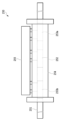
- FIG. 1 is a configuration diagram showing the installation of a char main powder flow meter 250 according to the present disclosure.
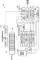
- FIG. 2 is a block diagram showing details of a char main powder flowmeter 250 according to the present disclosure.
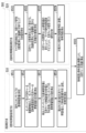
- 5 is a flow chart illustrating a flow measurement method 500 according to the present disclosure.
- the fluid measurement device and method disclosed herein are described as relating to a system for feeding coal char to a gasifier in a coal gasification power generation system. However, this is for illustrative purposes only, and the fluid measurement device and method disclosed herein are not limited to coal char.
- FIG. 2 is a block diagram illustrating a system for coal char recovery and resupply in a gasifier including flow measurement devices (main char powder flow meter 250 and branch char powder flow meter 270) according to the present disclosure. As shown in Fig.
- the system for recovering and resupplying coal char in the gasification furnace includes a char recovery facility 210 for recovering coal char generated in the gasification furnace, a char lock hopper 220 disposed downstream of the char recovery facility 210, a char feed hopper 230 disposed downstream of the char lock hopper 220, a char transport main pipe 240 that connects the char recovery facility 210 to the char feed hopper 230 and transports the coal char to be delivered, a char main powder flow meter 250 disposed downstream of the char feed hopper 230 and measures the flow rate of coal char flowing through the char transport main pipe 240, a char transport branch pipe 260 branched downstream of the char main powder flow meter 250, and a char transport branch pipe powder flow meter 270 that measures the flow rate of coal char flowing through each of the branches of the char transport branch pipe 260.
- a configuration in which two char transport branch pipe powder flow meters 270 are arranged is depict
- the char recovery equipment 210 is a mechanism for recovering coal char discharged together with the gas generated in the gasification furnace, and may have a high-temperature filter, etc.
- a charlock hopper 220 is arranged downstream of the char recovery equipment 210, and the charlock hopper 220 has the function of temporarily storing coal char, cutting out a predetermined amount, and sending it to the char feed hopper 230.
- the char feed hopper 230 temporarily stores pressurized coal char to be supplied to the gasification furnace, and cuts out a predetermined amount and sends it out.
- the coal char sent out from the char feed hopper 230 is transported inside the char transport main pipe 240 by nitrogen gas, and the flow rate is measured by the char main pipe powder flow meter 250.
- coal char sent out from the char main pipe powder flow meter 250 is transported inside the char transport branch pipe 260, and the flow rate is measured by each of the char branch pipe powder flow meters 270.
- Coal char is fed to the gasifier at the desired flow rate based on flow measurements in the char main powder flow meter 250 and the char delivery branch pipe 260.
- the main char powder flowmeter 250 and the branch char powder flowmeter 270 are capacitance type, and measure the density and flow rate of the coal char based on the capacitance of the coal char flowing inside the main char transport pipe 240 and the branch char transport pipe 260.
- the char main powder flowmeter 250 includes a density measurement sensor electrode 252 and two flow rate measurement sensor electrodes 253a and b connected to a sensor pipe (pipe) 251.
- the density measurement sensor electrode 252 is disposed between the two flow rate measurement sensor electrodes 253a and b.
- the density measurement sensor electrode 252 and the two flow rate measurement sensor electrodes 253a and b connected to the sensor pipe 251 are covered with a cast iron shield 254, and a control box 255 that controls the density measurement sensor electrode 252 and the two flow rate measurement sensor electrodes 253a and b is connected to the cast iron shield 254.
- the control box 255 and each sensor are connected by two lead wires.
- the material of the sensor pipe 251 is alumina ceramics, and the thickness of the sensor pipe 251 is 5 mm.
- the material of the density measurement sensor electrode 252 and the two flow rate measurement sensor electrodes 253a, b is a good conductor such as copper foil, and the lead wires attached to the electrodes are Junflon single wires with a diameter of ⁇ 0.6 to 0.8 mm.
- GFRP is primarily used for the sensor pipe 251, but in terms of the heat resistance issue mentioned above, alumina-based ceramics are used for the sensor pipe 251 in the fluid measuring devices according to the present disclosure (main char powder flow meter 250 and branch char powder flow meter 270).
- alumina-based ceramics generally have high heat resistance, they lack toughness and are inferior in impact resistance compared to GFRP.
- the thickness of the sensor pipe 251 is set to 5 mm, which is thicker than that of capacitance-type measuring devices according to the prior art, to ensure impact resistance (for example, in Patent Document 1, the thickness is 3.5 mm).
- the material and thickness of the sensor pipe 251 may be set arbitrarily according to the design, taking into consideration heat resistance, impact resistance, specific capacitance, etc., and other materials may be used and other thicknesses may be set.
- the coal char to be measured passes through the inside of the sensor pipe 251.
- the density measuring sensor electrode 252 and the flow rate measuring sensor electrodes 253a, b face each other across the sensor pipe 251, and a carrier signal voltage generated by an oscillator is applied to the sensor pipe 251 through each lead wire.
- An AC current generated by the carrier signal voltage flows through each lead wire, and this AC current is amplitude modulated according to the change in capacitance caused by the change in the flow rate of the char.
- This AC current, amplitude modulated according to the capacitance is taken into the control box 255 through each lead wire.
- a capacitance measuring means for determining density Inside the control box 255, a capacitance measuring means for determining density, two capacitance measuring means for determining flow rate, and a control means are implemented, as will be described in detail in FIG. 4 (the operation of the char main powder flowmeter 250 will be described in detail in FIG. 4).
- FIG. 4 is a configuration diagram showing the details of the main char powder flowmeter 250 according to the present disclosure.
- the branch char powder flowmeter 270 can also have a similar configuration.
- the fluid measurement device (main char powder flowmeter 250 and branch char powder flowmeter 270) according to the present disclosure includes a density determination capacitance measurement means 410 in the sensor pipe 251, and two flow rate determination capacitance measurement means 420a, b are connected to the sensor pipe 251 on either side of the density determination capacitance measurement means 410.
- the part of the sensor pipe 251 to which the sensors of each measurement means are connected is covered with an electromagnetic shield 430 to electromagnetically shield each sensor from the outside air and reduce the effect on capacitance due to the humidity of the outside air, etc.
- a control means 440 is connected to the density determination capacitance measurement means 410 and each of the two flow rate determination capacitance measurement means 420a, b.
- the density determination capacitance measuring means 410 includes the density measurement sensor electrode 252 and capacitance measuring device 411 described above.
- the density measurement sensor electrode 252 has a pair of electrodes installed opposite to each other on the outer surface of the sensor pipe 251, and may be, for example, in a strip shape.
- the capacitance measuring device 411 is a digital device. This is because, as described above, the thickness of the sensor pipe 251 is set to 5 mm, which increases the inherent capacitance of the sensor pipe 251, and therefore the capacitance measuring device 411 needs to have a wider measurement range.
- Coal char has a high capacitance at room temperature, but has a low capacitance at a high temperature just after being generated in the gasification furnace.
- the fluid (including coal char and nitrogen gas) flowing inside the char transport main pipe 240 and the char transport branch pipe 260 has a non-uniform flow rate and an unstable solid-gas ratio. From this perspective, the capacitance measuring device 411 needs to have a wider measurement range, and therefore a digital device with a wider measurement range is preferable.
- the capacitance measuring means for flow velocity determination 420a includes the above-mentioned sensor electrode for flow velocity measurement 253a, an AC amplifier (AC amplifier) 421, a rectifier 422, a low-pass filter (LPF) 423, a DC amplifier (DC amplifier) 424, and a first analog-to-digital converter (AD converter) 425, which are connected in series. Furthermore, the capacitance measuring means for flow velocity determination 420a further includes an oscillator 426 connected to the sensor electrode for flow velocity measurement 253a, and a second analog-to-digital converter 427 that converts the signal output from the low-pass filter 423 into a digital value.
- AC amplifier AC amplifier
- LPF low-pass filter
- DC amplifier DC amplifier
- AD converter first analog-to-digital converter
- the capacitance measuring means for flow velocity determination 420b has the same configuration as the capacitance measuring means for flow velocity determination 420a.
- Each of the flow velocity measurement sensor electrodes 253a, b of the capacitance measurement means for determining flow velocity 420a, b has a pair of electrodes installed facing each other on the outer surface of the upstream and downstream sides of the sensor pipe 251 where the coal char flows, and may be, for example, in a band shape.
- the shape of each of the density measurement sensor electrode 252 and the flow velocity measurement sensor electrodes 253a, b may be, for example, a spiral shape or a comb-like shape. When the electrode shape is a comb-like shape, the tip of the electrode is sharpened to make it less likely to cause the skin effect, since the effective area of the electrode decreases due to the skin effect when the carrier frequency is increased.
- each sensor density measurement sensor electrode 252 and flow rate measurement sensor electrodes 253a, b
- the sensors will interfere with each other, which may cause errors when measuring capacitance.
- the density measurement sensor electrode 252 and the flow rate measurement sensor electrodes 253a, b have different frequencies of the AC voltage oscillation source, so there is almost no interference between them.
- the flow rate measurement sensor electrodes 253a, b can be installed upstream and downstream of the sensor pipe 251, sandwiching the density measurement sensor electrode 252, which allows the char main powder flowmeter 250 and char branch powder flowmeter 270 to be made compact while ensuring the distance between the flow rate measurement sensor electrodes 253a, b.
- the AC amplifier 421 arbitrarily sets the gain value within a predetermined range.
- the rectifier 422 rectifies the amplitude-modulated carrier signal, and the low-pass filter 423 has a predetermined cutoff frequency.
- the DC amplifier 424 arbitrarily sets the offset value and gain value within a predetermined range.
- the first analog-to-digital converter 425 converts the output value of the DC amplifier 424 into a digital value and transmits it to the control means 440.
- the second analog-to-digital converter 427 converts the output value of the low-pass filter 423 into a digital value and transmits it to the control means 440.
- the AC amplifier 421 and the DC amplifier 424 are analog devices, and are set so that the gain value is automatically adjusted and variable by a digital signal. This is due to the fact that the flow rate of the coal char described above is uneven.
- the char main powder flowmeter 250 and the char branch powder flowmeter 270 are configured so that the pulsation of the coal char is captured as a change in voltage by the AC amplifier 421, which is an analog device, and converted into a digital value by the first analog-digital converter 425.
- the flow rate measurable range of the first analog-digital converter 425 needs to be set so that it falls within a range that can be calculated with respect to the range of the DC amplifier 424 located upstream.
- the solid-gas ratio of the fluid (including coal char and nitrogen gas) flowing into the sensor pipe 251 is not stable, and therefore it is not possible to fall within the measurable range by simply adjusting the gain value of the DC amplifier 424. For this reason, the gain value of the AC amplifier 421 must be variable accordingly.
- the fluid measurement device (main char powder flowmeter 250 and branch char powder flowmeter 270) according to the present disclosure is set so that the offset value setting of the DC amplifier 424 can also be automatically adjusted.
- the automatic adjustment of the gain values for the AC amplifier 421 and DC amplifier 424 and the offset value for the DC amplifier 424 will be described in detail later.
- the oscillator 426 generates a carrier signal of a predetermined frequency (1 MHz or higher).
- the oscillator 426 can also modulate the amplitude of the carrier signal by a change in capacitance caused by a change in density of the coal char.
- the electrode shapes of the density measuring sensor electrode 252 and the flow rate measuring sensor electrodes 253a, b are, for example, comb-shaped, to maximize the detection effect per electrode area.
- the control means 440 includes a powder density calculation means 441, a flow rate calculation means 442, a flow rate calculation means 443, an offset value setting means 444, a gain value setting means 445, and a gain value and offset value optimum value calculation means 446.
- the powder density calculation means 441 inputs a measured value from the capacitance measuring device 411 of the density determination capacitance measuring means 410, and outputs a calculated value to the flow rate calculation means 443.
- the flow rate calculation means 442 inputs a measured value from the first analog-digital converter 425 of each of the flow rate determination capacitance measuring means 420a, b, and outputs a calculated value to the flow rate calculation means 443.
- the flow rate calculation means 442 calculates the time it takes for the coal char to reach the downstream flow rate measurement sensor electrode 253a from the upstream flow rate measurement sensor electrode 253b based on the correlation between the capacitance changes upstream and downstream.
- the flow rate calculation means 443 calculates the flow rate by multiplying the measurement results of the density and flow rate.
- the offset setting means 444 receives a signal input from the gain value and offset value optimum value calculation means 446, and outputs a signal for setting the offset value appropriately to the DC amplifier 424 of each of the capacitance measurement means for determining flow velocity 420a, b.
- the offset value is set to be automatically adjusted from the viewpoint of widening the measurable range. That is, the gain value and offset value optimum value calculation means 446 calculates an optimum offset value based on the output of the first analog-digital converter 425 and the output of the second analog-digital converter 427, and outputs the optimum value to the DC amplifier 424 as a digital signal via the offset value setting means 444. This series of controls is performed automatically, so the offset value control of the DC amplifier 424 is automatically adjusted.
- the gain value setting means 445 receives a signal input from the gain value and offset value optimum value calculation means 446, and outputs a signal for appropriately setting the gain value to the AC amplifier 421 and DC amplifier 424 of each of the capacitance measurement means for flow velocity determination 420a, b.
- the gain value is set to be automatically adjusted from the viewpoint of widening the measurable range. That is, the gain value and offset value optimum value calculation means 446 calculates an optimum value for the gain value based on the output of the first analog-digital converter 425 and the output of the second analog-digital converter 427, and outputs the optimum value to the AC amplifier 421 and DC amplifier 424 as a digital signal via the gain value setting means 445. This series of controls is performed automatically, so the control of the gain values of the AC amplifier 421 and DC amplifier 424 is automatically adjusted.
- the density measurement sensor electrode 252 is installed between the two flow velocity measurement sensor electrodes 253a, b of the sensor pipe 251, but the density measurement sensor electrode 252 may be installed outside the flow velocity measurement sensor electrodes 253a, b.
- the fluid measuring device (main char powder flowmeter 250 and branch char powder flowmeter 270) according to the present disclosure is enclosed in a body made of metal (e.g., austenitic stainless steel, etc.) and placed in the gasification furnace system shown in FIG. 1.
- a body made of metal e.g., austenitic stainless steel, etc.
- an O-ring and a cushion gasket are placed between the main char powder flowmeter 250 and the body to prevent direct contact between the two.
- the O-ring and the cushion gasket are also made of a material that can withstand that temperature.
- the O-ring may be a perfluoroelastomer having a heat-resistant temperature of 330°C
- the cushion gasket may be made of the same or similar material as the gasket for the coal char piping.
- the fluid measuring device may further include a pressure-resistant feedthrough terminal (ground feedthrough) to prevent coal char from leaking to the outside from the broken part.
- the material of the pressure-resistant feedthrough terminal may be polytetrafluoroethylene, etc.
- FIG. 5 is a flowchart showing a flow rate measurement method 500 according to the present disclosure.
- the flow rate measurement method 500 includes a density determination capacitance measurement method 510 and a flow rate determination capacitance measurement method 520.
- the density determination capacitance measurement method 510 is performed by the density determination capacitance measurement means 410 described above
- the flow rate determination capacitance measurement method 520 is performed by the flow rate determination capacitance measurement means 420a, b described above.
- the density determination capacitance measurement method 510 includes measuring the specific capacitance of the manufactured sensor pipe 251 (S511), detecting the total value of the specific capacitance of the sensor pipe 251 and the capacitance of the coal char using the sensor pipe 251 and the coal char as interelectrode materials (S512), calculating the difference between the detected total value of the specific capacitance of the sensor pipe 251 and the capacitance of the coal char and the specific capacitance of the sensor pipe 251 obtained in advance (S513), and transmitting the calculated difference value to the powder density calculation means 441 as the capacitance of the coal char to calculate the powder density (S514).
- the capacitance measurement for flow velocity determination 520 includes generating a carrier signal and applying the carrier signal between the sensor electrodes for flow velocity measurement 253a, b to generate an AC current (S521), measuring the amplitude of the AC current flowing between the sensor electrodes for flow velocity measurement 253a, b, which changes in response to the density change of the coal char (S522), measuring a signal corresponding to the density of the coal char by amplitude modulating the carrier signal using the change in capacitance due to the density change of the coal char (S523), and transmitting the measured signal to the flow velocity calculation means 442 to calculate the powder flow velocity (S524).
- the flow rate of the coal char is calculated (S501) by multiplying the powder density calculated by the above method by the powder flow rate.
- the density determination capacitance measurement method 510 using the density determination capacitance measurement means 410 will be described in detail.
- the density measurement sensor electrode 252 detects the total value of the specific capacitance of the sensor pipe 251 and the capacitance of the coal char, with the sensor pipe 251 and the coal char as interelectrode materials.
- the capacitance measurement device 411 calculates the difference between the detected total value of the specific capacitance of the sensor pipe 251 and the capacitance of the coal char and the specific capacitance of the sensor pipe 251 acquired in advance (offset by the specific capacitance of the sensor pipe 251), and outputs the calculated value as the capacitance of the coal char to the powder density calculation means 441 of the control means 440.
- the thickness of the sensor pipe 251 is set to be thick as described above, and the specific capacitance of the sensor pipe 251 is large, so such an offset is necessary.
- the capacitance measurement means for determining flow velocity 420a, b measures the capacitance of the coal char using sensor electrodes for measuring flow velocity 253a, b installed upstream and downstream of the sensor electrode for measuring density 252, and measures the passage time of the coal char between the two electrodes based on the correlation.
- the oscillator 426 generates a carrier signal for detecting the change in capacitance.
- the voltage of the carrier signal generated between the flow velocity measurement sensor electrodes 253a, b is applied, an AC current flows between the flow velocity measurement sensor electrodes 253a, b.
- the dielectric constant between the flow velocity measurement sensor electrodes 253a, b changes in response to the change in density of the coal char, and the capacitance of the coal char changes.
- the amplitude of the AC current flowing through the flow velocity measurement sensor electrodes 253a, b changes in response to the change in capacitance of the coal char.
- a signal corresponding to the density of the coal char can be measured by amplitude modulating the carrier signal due to the change in capacitance caused by the density change of the coal char.
- the AC amplifier 421 amplifies the amplitude-modulated carrier signal to improve detection accuracy.
- the solid-gas ratio of the fluid flowing through the sensor pipe 251 is not stable, so the gain value of the AC amplifier 421 is automatically adjusted based on the outputs of the first analog-digital converter 425 and the second analog-digital converter 427 so that it becomes the optimum value of the gain value calculated by the gain value and offset value optimum value calculation means 446 of the control means 440.
- the output of the AC amplifier 421 is input to the rectifier 422.
- the amplified signal is rectified and input to the low-pass filter 423.
- the low-pass filter 423 high-frequency components due to the carrier signal are removed from the rectified signal, and only the components whose capacitance changes in proportion to the density of the coal char are extracted.
- the offset setting means 444 sends a digital signal to the DC amplifier 424 so that the offset value becomes the appropriate offset value calculated by the gain value and offset value appropriate value calculation means 446 so that the DC amplifier 424 does not become saturated.
- the gain value setting means 445 sends a digital signal to the AC amplifier 421 and the DC amplifier 424 so that the gain values of the AC amplifier 421 and the DC amplifier 424 become the appropriate gain values calculated by the gain value and offset value appropriate value calculation means 446.
- the powder flow rate measuring device and powder flow rate measuring method disclosed herein are capable of measuring the flow rate with high accuracy even of powder fluids that are at high temperature and pressure and have an unstable solid-gas ratio, such as coal char in a gasifier.
- Such powder flow rate measuring device and powder flow rate measuring method are expected to be applied to coal gasification power generation systems such as IGCC and IGFC.
- Capacitance measuring means 2 AC signal oscillator 3 Measurement sensor 4 Reference sensor 5a Resistor 5b Resistor 5c Resistor 6 Amplifier 7 Amplifier 8 Differential amplifier 9 Powder data detection amplifier 210 Char recovery equipment 220 Char lock hopper 230 Char feed hopper 240 Char transport main pipe 250 Char main powder flow meter 251 Sensor pipe (pipe) 252 Density measuring sensor electrode 253a Flow velocity measuring sensor electrode 253b Flow velocity measuring sensor electrode 254 Cast iron shield 260 Char transport branch pipe 270 Char branch pipe Powder flow meter 410 Density determining capacitance measuring means 411 Capacitance measuring device 420a Flow velocity determining capacitance measuring means 420b Flow velocity determining capacitance measuring means 421 AC amplifier (AC amplifier) 422 Rectifier 423 Low-pass filter (LPF) 424 Direct current amplifier (DC amplifier) 425 First analog-to-digital converter (AD converter) 425 First analog-digital converter 426 Oscillator 427 Second analog-digital converter 430
Landscapes
- Physics & Mathematics (AREA)
- Fluid Mechanics (AREA)
- General Physics & Mathematics (AREA)
- Measuring Volume Flow (AREA)
Abstract
高温・高圧であり、且つ固気比の安定しない粉体の流量を高精度に測定する流量測定装置及び流量測定方法を提供する。本開示による粉体流量測定装置は、交流アンプと、交流アンプの出力側に配置される直流アンプと、直流アンプの出力側に配置される第1のアナログデジタル変換器と、交流アンプと直流アンプとの間に分岐されて配置される第2のアナログデジタル変換器とを含み、第1及び第2のアナログデジタル変換器から出力されるデジタル信号に基づいて、オフセット値及びゲイン値の適正値を算出するゲイン値及びオフセット値適正値算出手段をさらに含み、オフセットの適正値をデジタル信号として直流アンプに送信することにより、直流アンプのオフセット値を自動調整し、ゲイン値の適正値をデジタル信号として交流アンプと直流アンプに送信することにより、交流アンプと直流アンプのゲイン値を自動調整する。
Description
本開示は、粉体流量測定装置及び粉体流量測定方法に関し、より詳細には、測定の対象となる粉体流体の静電容量の変化を測定することにより当該流体の流量を測定する静電容量式の粉体流量測定装置及び粉体流量測定方法に関する。
従来、例えば、ガス化炉に吹き込まれる微粉炭等の粉体を測定する手段として、粉体流量測定装置が用いられている。粉体流量測定装置を用いて粉体流量を測定する方法には、例えば、粉体の密度(t/m3)と流速(m/s)を測定し、これらと粉体を吹き込む管の断面積(m2)を乗算して粉体の流量(t/s)を求める方法がある。ここで、粉体の密度または流速を測定する方式には、静電容量の変化を測定することにより粉体の流量を測定する静電容量式や、マイクロ波の透過あるいは反射信号より管内の粉体の密度を求めるマイクロ波式等が知られている。
しかしながら、マイクロ波式は、センサパイプ(管路)にマイクロ波を通すため、当該マイクロ波を通す部分のみ肉薄にしなければならず、搬送ガスの圧力を上げることができない。また、マイクロ波の出力を上げると、被測定物が熱を持つ可能性がある。そのため、マイクロ波式は、石炭ガス化炉のように管路内の圧力が高圧の場合には使用に適さない。そこで、石炭ガス化炉などの管路内の圧力が高圧の場合に、粉体の密度または流速を測定する方式には、静電容量式が用いられている。
図1は、従来の静電容量式の粉体流量測定装置内の静電容量測定手段1を表す構成図である。静電容量測定手段1は、交流信号発振器2と、アナログ式の測定用センサ3と、アナログ式の基準用センサ4と、アンプ6および7と、差動増幅器8を備えている。交流信号発振器2は、測定用センサ3、基準用センサ4および抵抗5aないし5cから構成されるブリッジ回路と並列に接続されている。測定用センサ3および基準用センサ4は、それぞれアンプ6および7に接続され、アンプ6および7は差動増幅器8に接続されている。また、静電容量測定手段1は、差動増幅器8に接続された粉体データ検出増幅器9と、粉体データ検出増幅器9に接続されたLPF10を備えている。
従来の静電容量式の粉体流量測定装置は、例えば、静電容量測定手段1を管路の上流と下流の2箇所に備える2センサ方式を用いて静電容量を精密に測定している。具体的には、2箇所の静電容量測定手段1の一方又は両方で測定した静電容量の平均値を粉体の密度として用い、上流と下流で測定した静電容量の変化分の相関から粉体の流速を求めている。この場合、静電容量測定手段1では、静電容量を測定する際に管路等の固有静電容量をキャンセルするため、基準コンデンサ等の基準用センサ4を用いている。
このように、従来技術による静電容量式の粉体流量測定装置は、基準用センサを別途設置する必要があるため、以前では、装置のコンパクト化が困難とされていた。しかしながら、近年では、これらの課題を解決するための技術提案もされている。例えば、被測定対象となる粉体の密度を測定する密度測定用センサと当該粉体の流速を測定する流速測定用センサとで、交流電圧の発振源の周波数を変えることにより、各センサにおける交流電圧印加時の相互的な干渉を抑制することで、当該基準コンデンサを不要とする技術が報告されている(例えば、特許文献1参照)。このようなことから、静電容量式は、例えばガス化炉の管路内を流れる粉体の流量測定技術として、今後更なる普及と発展が期待できる流量測定技術と考えられる。
一方で、粉体の流量測定技術に対しては、高温高圧の粉体流体に対する高精度な流量測定等、更なる要求も掲げられている。その一例として、ガス化炉における石炭チャーの流量測定が挙げられる。
ガス化炉を有する石炭ガス化発電システム、例えば、石炭ガス化複合発電(IGCC)システムや、石炭ガス化燃料電池複合発電(IGFC)システムでは、燃料である微粉炭を当該ガス化炉内で燃焼させ、発生する石炭ガスをガスタービンに供給することにより、発電が行われる。この石炭ガスの生成反応において、燃料(微粉炭)の一部は石炭チャーと呼ばれる未反応物として残ることが知られており、当該石炭チャーの粉体は、回収された後、再度ガス化炉に供給され、石炭ガスの生成反応に寄与する。
石炭チャーは、回収設備で回収された後、窒素ガス等の不活性ガスと共に加圧(約5MPaまで)されながらガス化炉に供給される。したがって、燃料(微粉炭)と同様に、この石炭チャーに対しても、供給過程における流量を高精度に測定することは、石炭ガス化発電システムの安定な稼働を行う上で重要となる。
石炭チャーは、約250℃もの温度に達し得ることが知られている。一方、特許文献1に記載されるような既存の静電容量式では、センサパイプとしてガラス繊維強化プラスチック(Glass-Fiber-Reinforced Plastics:GFRP)が、主に用いられる。一般に、GFRPは、エポキシ樹脂等のプラスチックを基材とするため、耐熱性に乏しい。したがって、既存の静電容量式では、上述した石炭チャーのような高温の流体を測定することは困難である。
また、石炭チャーは常温では高い静電容量を有するのに対し、ガス化炉で生成されたばかりの高温の状態では低い静電容量を有する。加えて、ガス化炉の系統を流れる石炭チャーは、流量が不均一であり固気比が安定しないという特徴も有する。このため、当該石炭チャーの流量計は、測定可能レンジが広域である必要があり、既存の静電容量式では、測定可能レンジをオーバーするため、流量測定ができないという課題もある。
本開示は、上記のような課題に対して鑑みてなされたものであり、その目的とするところは、ガス化炉における石炭チャーのような高温高圧であり、且つ固気比の安定しない粉体の流量を高精度に測定することを実現する流量測定装置及び流量測定方法を提供することにある。
このような目的を達成するため、本開示では、粉体が流されるセンサパイプ内の静電容量の変化を測定することにより粉体流量を測定する静電容量式の粉体流量測定装置であって、センサパイプ内の静電容量に応じた信号を測定する密度判定用静電容量測定手段と、測定した信号から粉体密度を演算する粉体密度演算手段と、センサパイプ内の静電容量に応じた信号からセンサパイプの固有静電容量分をオフセットして粉体の静電容量のみの変化分を増幅して測定する第1及び第2の流速判定用静電容量測定手段と、測定した各変化分の相関に基づいて粉体流速を演算する粉体流速演算手段と、粉体密度と粉体流速とから粉体流量を演算する粉体流量演算手段と、を備え、第1及び第2の流速判定用静電容量測定手段は、測定した各変化分に関する信号を受信し、増幅する、アナログデバイスである交流アンプと、交流アンプが出力した信号に対し、オフセット値及びゲイン値を設定して直流増幅する直流アンプと、前直流アンプが出力するアナログ信号をデジタル信号に変換する第1のアナログデジタル変換器と、交流アンプと直流アンプとの間に分岐されて配置され、直流アンプに入力される前の信号をデジタル信号に変換する第2のアナログデジタル変換器と、をさらに備え、粉体流量測定装置は、第1及び第2のアナログデジタル変換器から出力されるデジタル信号に基づいて、オフセット値及びゲイン値の適正値を算出するゲイン値及びオフセット値適正値算出手段をさらに備え、オフセット値の適正値をデジタル信号として直流アンプに送信することにより、直流アンプのオフセット値を自動調整し、ゲイン値の適正値をデジタル信号として交流アンプと直流アンプに送信することにより、交流アンプと直流アンプのゲイン値を調整することを特徴とする粉体流量測定装置を提供する。
また、本開示では、粉体が流されるセンサパイプ内の静電容量の変化を測定することにより粉体流量を測定する静電容量式の粉体流量測定方法であって、製作したセンサパイプの固有静電容量を測定することと、センサパイプおよび被測定物を電極間物質として、センサパイプの固有静電容量及び被測定物の静電容量の合計値を検出することと、検出した合計値と、製作したセンサパイプの固有静電容量との差を算出することと、算出された差の値を被測定物の静電容量として粉体密度演算手段に送信し、粉体密度を算出することと、キャリア信号を発生させ、キャリア信号を流速測定用センサ電極間に印加することで交流電流を発生させることと、被測定物の密度変化に応じて変化する、流速測定用センサ電極間に流れる交流電流の振幅を測定することと、被測定物の密度変化による静電容量の変化によって、キャリア信号を振幅変調することにより、被測定物の密度に応じた信号を計測することと、計測された信号を流速演算手段に送信し、粉体流速を算出することと、粉体密度と粉体流速とから粉体流量を乗算することで演算することと、を備える粉体流量測定方法を提供する。
本開示による粉体流量測定装置及び粉体流量測定方法は、ガス化炉における石炭チャーのような、高温・高圧であり、且つ固気比が安定しない粉体流体も高精度に流量測定することを可能にする。
以下に、図面を参照しながら本開示の種々の実施形態について詳細に説明する。同一又は類似の参照符号は同一又は類似の要素を示し重複する説明を省略する場合がある。材料及び数値は例示を目的としており本開示の技術的範囲の限定を意図していない。以下の説明は、一例であって本開示の一実施形態の要旨を逸脱しない限り、一部の構成を省略若しくは変形し、又は追加の構成とともに実施することができる。
以下における説明の文脈では、本開示による流体測定装置及び流体測定方法は、石炭ガス化発電システムにおける石炭チャーのガス化炉への送給するための系統に関するものとして述べられる。しかしながら、これは例示を目的としており、本開示による流体測定装置及び流体測定方法は、石炭チャーに関するものに限定されない。
(流量測定装置の構成)
以下に、本開示による流量測定装置の構成について、図面を参照して詳細に説明する。
以下に、本開示による流量測定装置の構成について、図面を参照して詳細に説明する。
(石炭チャー回収・再供給のシステムの全体構成)
図2は、本開示による流体測定装置(チャー本管粉体流量計250及びチャー支管粉体流量計270)を含むガス化炉における石炭チャーの回収及び再供給のための系統を示すブロック図である。図2に示される通り、ガス化炉における石炭チャーの回収及び再供給のための系統は、ガス化炉で生成した石炭チャーを回収するチャー回収設備210と、チャー回収設備210の下流に配置されるチャーロックホッパ220と、チャーロックホッパ220の下流に配置されるチャーフィードホッパ230と、チャー回収設備210からチャーフィードホッパ230までを連結し、送出される石炭チャーが搬送されるチャー搬送管本管240と、チャーフィードホッパ230の下流に配置され、チャー搬送管本管240を流れる石炭チャーの流量を測定するチャー本管粉体流量計250と、チャー本管粉体流量計250の下流において分岐されたチャー搬送管支管260と、チャー搬送管支管260の分岐された各々の中を流れる石炭チャーの流量を測定するチャー支管粉体流量計270と、を含む。図2では、例として、チャー支管粉体流量計270が2体配置された形態が描写されている。
図2は、本開示による流体測定装置(チャー本管粉体流量計250及びチャー支管粉体流量計270)を含むガス化炉における石炭チャーの回収及び再供給のための系統を示すブロック図である。図2に示される通り、ガス化炉における石炭チャーの回収及び再供給のための系統は、ガス化炉で生成した石炭チャーを回収するチャー回収設備210と、チャー回収設備210の下流に配置されるチャーロックホッパ220と、チャーロックホッパ220の下流に配置されるチャーフィードホッパ230と、チャー回収設備210からチャーフィードホッパ230までを連結し、送出される石炭チャーが搬送されるチャー搬送管本管240と、チャーフィードホッパ230の下流に配置され、チャー搬送管本管240を流れる石炭チャーの流量を測定するチャー本管粉体流量計250と、チャー本管粉体流量計250の下流において分岐されたチャー搬送管支管260と、チャー搬送管支管260の分岐された各々の中を流れる石炭チャーの流量を測定するチャー支管粉体流量計270と、を含む。図2では、例として、チャー支管粉体流量計270が2体配置された形態が描写されている。
チャー回収設備210は、ガス化炉内で生成したガスと共に排出される石炭チャーを回収する機構であり、高温フィルタ等を有し得る。このチャー回収設備210の下流にはチャーロックホッパ220が配置されており、当該チャーロックホッパ220は、石炭チャーを一時的に貯留し、所定の量に切り出してチャーフィードホッパ230へ送給する機能を有する。チャーフィードホッパ230は、ガス化炉に供給するために加圧された石炭チャーを一時的に貯留し、所定の量に切り出して送出する。そして、チャーフィードホッパ230から送出された石炭チャーは、窒素ガスによってチャー搬送管本管240内を搬送され、チャー本管粉体流量計250にて流量測定が行行われる。さらに、チャー本管粉体流量計250から送出された石炭チャーは、チャー搬送管支管260内を搬送され、チャー支管粉体流量計270の各々において流量測定される。石炭チャーは、チャー本管粉体流量計250及びチャー搬送管支管260における流量測定に基づいて、所望の流量でガス化炉に供給される。
チャー本管粉体流量計250及びチャー支管粉体流量計270は、静電容量式であり、チャー搬送管本管240及びチャー搬送管支管260の内部を流れる石炭チャーの静電容量に基づいて、当該石炭チャーの密度及び流速を測定する。
(流量測定装置の構成の詳細)
図3は、本開示によるチャー本管粉体流量計250を設置した様子を表す構成図である。なお、チャー支管粉体流量計270も同様の構成とすることができる。チャー本管粉体流量計250は、センサパイプ(管路)251に連結された、密度測定用センサ電極252と、2つの流速測定用センサ電極253a、bを含む。密度測定用センサ電極252は、2つの流速測定用センサ電極253a、bの間に配置される。センサパイプ251に連結された密度測定用センサ電極252と、2つの流速測定用センサ電極253a、bは、鋳鉄製シールド254で覆われており、鋳鉄製シールド254には、密度測定用センサ電極252と、2つの流速測定用センサ電極253a、bを制御する制御BOX255が接続されている。制御BOX255と各センサとは、2本のリード線で接続されている。
図3は、本開示によるチャー本管粉体流量計250を設置した様子を表す構成図である。なお、チャー支管粉体流量計270も同様の構成とすることができる。チャー本管粉体流量計250は、センサパイプ(管路)251に連結された、密度測定用センサ電極252と、2つの流速測定用センサ電極253a、bを含む。密度測定用センサ電極252は、2つの流速測定用センサ電極253a、bの間に配置される。センサパイプ251に連結された密度測定用センサ電極252と、2つの流速測定用センサ電極253a、bは、鋳鉄製シールド254で覆われており、鋳鉄製シールド254には、密度測定用センサ電極252と、2つの流速測定用センサ電極253a、bを制御する制御BOX255が接続されている。制御BOX255と各センサとは、2本のリード線で接続されている。
ここでは一例として、センサパイプ251の材質は、アルミナ系セラミックスであり、センサパイプ251の肉厚は、5mmとする。また、密度測定用センサ電極252と2つの流速測定用センサ電極253a、bの材質は、銅箔等の良導体とし、電極に取り付ける各リード線は、ジュンフロン単線の径はφ0.6~0.8mmとする。
特許文献1に記載されるような従来技術による静電容量式の流量測定装置では、センサパイプ251にはGFRPが主に用いられるが、上述した耐熱性の課題の観点から、本開示による流体測定装置(チャー本管粉体流量計250及びチャー支管粉体流量計270)では、センサパイプ251にはアルミナ系セラミックスを適用している。但し、アルミナ系セラミックスは、一般に、高い耐熱性を有する反面、靭性に乏しくGFRPに比べて耐衝撃性が劣る。したがって、本開示による流体測定装置(チャー本管粉体流量計250及びチャー支管粉体流量計270)では、センサパイプ251の肉厚は、従来技術による静電容量式の測定装置に比べ、5mmと厚く設定することで耐衝撃性を担保している(例えば、特許文献1では、当該肉厚は3.5mmである)。尚、センサパイプ251に適用される材料及び肉厚の厚さは、耐熱性、耐衝撃性、固有静電容量等を考慮し、設計に応じて任意に設定されてよく、他の材料が適用されても、他の肉厚で設定されてもよい。
チャー本管粉体流量計250において、被測定物である石炭チャーは、センサパイプ251の内部を通過する。密度測定用センサ電極252と流速測定用センサ電極253a、bは、センサパイプ251を挟んで対向しており、発振器により生成したキャリア信号電圧をセンサパイプ251に各リード線を介して印加する。各リード線にはキャリア信号電圧により生じる交流電流が流れ、この交流電流はチャーの流量変化による静電容量の変化に応じて振幅変調される。この静電容量に応じて振幅変調された交流電流は、各リード線を通じて制御BOX255に取り込まれる。制御BOX255の内部には、図4で詳細に説明するが、密度判定用静電容量測定手段、2つの流速判定用静電容量測定手段、および制御手段が実装されている(チャー本管粉体流量計250の動作については、図4で詳細に説明する)。
図4は、本開示によるチャー本管粉体流量計250の詳細を表す構成図である。なお、チャー支管粉体流量計270も同様の構成とすることができる。本開示による流体測定装置(チャー本管粉体流量計250及びチャー支管粉体流量計270)は、センサパイプ251に密度判定用静電容量測定手段410を含み、さらにセンサパイプ251に密度判定用静電容量測定手段410を挟んで2つの流速判定用静電容量測定手段420a、bが接続されている。各測定手段のセンサが接続されているセンサパイプ251の部分は、電磁シールド430で覆うことにより各センサを外気から電磁的に遮蔽し、外気の湿度等による静電容量への影響を少なくしている。密度判定用静電容量測定手段410と、2つの流速判定用静電容量測定手段420a、bの各々には、制御手段440が接続されている。
密度判定用静電容量測定手段410は、上述した密度測定用センサ電極252と静電容量測定器411を含む。密度測定用センサ電極252は、センサパイプ251の外表面に対向して設置される一対の電極を有し、例えば、帯状の形状であり得る。また、静電容量測定器411は、デジタルデバイスとする。これは、上述した通り、センサパイプ251の肉厚を5mmと厚く設定していることにより、当該センサパイプ251の固有静電容量が高くなっているため、静電容量測定器411はより広域な計測可能レンジを有する必要があるためである。また、石炭チャーは、常温では高い静電容量を有するのに対し、ガス化炉で生成されたばかりの高温の状態では低い静電容量を有する。加えて、チャー搬送管本管240やチャー搬送管支管260の内部を流れる流体(石炭チャー及び窒素ガスを含む)は、流量が不均一であり固気比が安定しないという特徴も有する。このような観点でも、静電容量測定器411はより広域な計測可能レンジを有する必要があり、故に計測可能レンジが広域なデジタルデバイスが好適である。
流速判定用静電容量測定手段420aは、上述した流速測定用センサ電極253aと、交流増幅器である交流アンプ(ACアンプ)421と、整流器422と、ローパスフィルタ(LPF)423と、直流増幅器である直流アンプ(DCアンプ)424と、第1のアナログデジタル変換器(AD変換器)425と、を含み、これらは直列に接続されている。さらに、流速判定用静電容量測定手段420aは、流速測定用センサ電極253aに接続された発振器426と、ローパスフィルタ423から出力される信号をデジタル値に変換する第2のアナログデジタル変換器427と、をさらに含む。尚、流速判定用静電容量測定手段420bも、流速判定用静電容量測定手段420aと同様の構成である。流速判定用静電容量測定手段420a、bの各流速測定用センサ電極253a、bは、センサパイプ251の石炭チャーが流れる上流および下流の外表面に対向して設置した各一対の電極を有し、例えば、帯状の形状であり得る。尚、密度測定用センサ電極252及び流速測定用センサ電極253a、bの各々の形状は、例えば、スパイラル形状や、櫛の歯状であってもよい。電極の形状を櫛の歯状にする場合、電極の先端を尖らせているのは、キャリア周波数を上げると表皮効果により電極の有効面積が減少するので、表皮効果を生じにくくするためである。
ここで、各センサ(密度測定用センサ電極252及び流速測定用センサ電極253a、b)に同一の周波数の発振源で交流電圧をかけると、各センサが相互に干渉を受けるため、静電容量を測定する際に誤差が生じるおそれがある。しかしながら、チャー本管粉体流量計250及びチャー支管粉体流量計270では、密度測定用センサ電極252と流速測定用センサ電極253a、bとで、交流電圧の発振源の周波数が異なるので、両者はほとんど干渉を受けずに済む。したがって、センサパイプ251の上流および下流に密度測定用センサ電極252を挟んで流速測定用センサ電極253a、bを設置することができ、これにより流速測定用センサ電極253a、b間の距離を確保しつつ、チャー本管粉体流量計250及びチャー支管粉体流量計270をコンパクトにすることができる。
交流アンプ421は、ゲイン値を所定の範囲で任意に設定する。整流器422は、振幅変調されたキャリア信号を整流し、ローパスフィルタ423は、所定のカットオフ周波数を有している。直流アンプ424は、オフセット値およびゲイン値を所定の範囲で任意に設定する。第1のアナログデジタル変換器425は、直流アンプ424の出力値をデジタル値に変換し制御手段440に送信する。第2のアナログデジタル変換器427は、ローパスフィルタ423の出力値をデジタル値に変換し制御手段440に送信する。
従来技術による静電式の流量測定装置とは異なり、本開示による流体測定装置(チャー本管粉体流量計250及びチャー支管粉体流量計270)では、交流アンプ421及び直流アンプ424は、アナログデバイスであり、且つデジタル信号によってゲイン値が自動調整により可変となるように設定されている。これは、上述した石炭チャーの流量が不均一であることに起因する。チャー本管粉体流量計250及びチャー支管粉体流量計270は、石炭チャーの脈動をアナログデバイスである交流アンプ421において、電圧の変化として捉え、第1のアナログデジタル変換器425でデジタル値に変換されるように構成される。このため、第1のアナログデジタル変換器425の流速測定可能レンジは、上流に配置される直流アンプ424のレンジに対して算出可能なレンジに収まるように設定される必要がある。しかしながら、上述の通り、センサパイプ251に流入する流体(石炭チャーと窒素ガスを含む)は、固気比が安定しないため、直流アンプ424のゲイン値調整のみでは、計測可能なレンジ内に収まらないことが分かっている。このため、交流アンプ421もそれに応じてゲイン値が可変である必要がある。但し、これだけでは計測可能なレンジ内に収まらないことも分かっているため、本開示による流体測定装置(チャー本管粉体流量計250及びチャー支管粉体流量計270)では、直流アンプ424のおけるオフセット値の設定も自動調整できるように設定されている。交流アンプ421及び直流アンプ424に対するゲイン値や直流アンプ424に対するオフセット値の自動調整については、後述の説明にて詳細に述べる。
発振器426は、所定の周波数(1MHz以上)のキャリア信号を発生させる。また、発振器426は、石炭チャーの密度変化による静電容量変化によってキャリア信号を振幅変調することができる。また、密度測定用センサ電極252及び流速測定用センサ電極253a、bの電極形状は、例えば櫛の歯状等にすることにより電極面積当たりの検出効果を最大に発揮させるようにしている。
制御手段440は、粉体密度演算手段441と、流速演算手段442と、流量演算手段443と、オフセット値設定手段444と、ゲイン値設定手段445と、ゲイン値及びオフセット値適正値算出手段446と、を含む。粉体密度演算手段441は、密度判定用静電容量測定手段410の静電容量測定器411から測定値を入力し、流量演算手段443に演算した値を出力する。流速演算手段442は、流速判定用静電容量測定手段420a、bの各々の第1のアナログデジタル変換器425から測定値を入力し、流量演算手段443に演算した値を出力する。具体的には、流速演算手段442は、上流と下流の静電容量変化の相関から石炭チャーが上流の流速測定用センサ電極253bから下流の流速測定用センサ電極253aに到達するまでの時間を算出する。流量演算手段443は、密度および流速の測定結果を乗算して流量を算出する。
オフセット設定手段444は、ゲイン値及びオフセット値適正値算出手段446から入力される信号を受信し、オフセット値を適正に設定する信号を、流速判定用静電容量測定手段420a、bの各々の直流アンプ424に出力する。オフセット値の設定は、上述の通り、計測可能範囲の広域化の観点から、自動調整で行われるように設定されている。即ち、ゲイン値及びオフセット値適正値算出手段446が第1のアナログデジタル変換器425の出力及び第2のアナログデジタル変換器427の出力に基づいて、オフセット値の適正値を算出し、当該適正値を、オフセット値設定手段444を介してデジタル信号として直流アンプ424に出力する。これら一連の制御は、自動で行われるため、直流アンプ424のオフセット値の制御は自動調整となる。
ゲイン値設定手段445は、ゲイン値及びオフセット値適正値算出手段446から入力される信号を受信し、ゲイン値を適正に設定する信号を、流速判定用静電容量測定手段420a、bの各々の交流アンプ421及び直流アンプ424に出力する。ゲイン値の設定は、上述の通り、計測可能範囲の広域化の観点から、自動調整で行われるように設定されている。即ち、ゲイン値及びオフセット値適正値算出手段446が第1のアナログデジタル変換器425の出力及び第2のアナログデジタル変換器427の出力に基づいて、ゲイン値の適正値を算出し、当該適正値を、ゲイン値設定手段445を介してデジタル信号として交流アンプ421及び直流アンプ424に出力する。これら一連の制御は、自動で行われるため、交流アンプ421及び直流アンプ424のゲイン値の制御は自動調整となる。
尚、上述の説明では、センサパイプ251の2つの流速測定用センサ電極253a、bの間に、密度測定用センサ電極252が設置されているが、流速測定用センサ電極253a、bの外側に、密度測定用センサ電極252が設置されてもよい。
また、本開示による流体測定装置(チャー本管粉体流量計250及びチャー支管粉体流量計270)は、金属(例えば、オーステナイト系ステンレス鋼等)製の胴体に内封された上で、図1に示されるガス化炉の系統に配置される。また、チャー本管粉体流量計250と胴体の間には、両者が直接接触しないようにOリング及びクッションガスケットが配置される。上述の通り、石炭チャーの温度は最高で250℃に達することが分かっているため、当該Oリング及びクッションガスケットも、当該温度に対応できる材料が適用されることが望ましい。例えば、Oリングは耐熱温度330℃を有するパーフルオロエラストマーであってよく、クッションガスケットは、石炭チャー配管用のガスケットと同一または類似の材料であってよい。
加えて、センサパイプ251が破損した場合を想定し、破損部から石炭チャーが外部に漏洩しないように、流体測定装置(チャー本管粉体流量計250及びチャー支管粉体流量計270)は耐圧貫通端子(グランドフィードスルー)をさらに含んでもよい。当該耐圧貫通端子の材料は、ポリテトラフルオロエチレン等であり得る。
(流量測定方法)
以下に、本開示による流量測定方法について、図面を参照して詳細に説明する。
以下に、本開示による流量測定方法について、図面を参照して詳細に説明する。
図5は、本開示による流量測定方法500を示すフローチャートである。図5に示される通り、流量測定方法500は、密度判定静電容量測定方法510と、流速判定用静電容量測定方法520と、を含む。密度判定静電容量測定方法510は、上述した密度判定用静電容量測定手段410により実行され、流速判定用静電容量測定方法520は、上述した流速判定用静電容量測定手段420a、bによって実行される。
さらに、密度判定静電容量測定方法510は、製作したセンサパイプ251の固有静電容量を測定すること(S511)と、センサパイプ251及び石炭チャーを電極間物質として、センサパイプ251の固有静電容量および石炭チャーの静電容量の合計値を検出すること(S512)と、検出したセンサパイプ251の固有静電容量と石炭チャーの静電容量の合計値と、予め取得しておいたセンサパイプ251の固有静電容量との差を算出すること(S513)と、算出された差の値を石炭チャーの静電容量として粉体密度演算手段441に送信し、粉体密度を算出すること(S514)と、を含む。
また、流速判定用静電容量測定520は、キャリア信号を発生させ、当該キャリア信号を流速測定用センサ電極253a、b間に印加することで交流電流を発生させること(S521)と、石炭チャーの密度変化に応じて変化する、流速測定用センサ電極253a、b間に流れる交流電流の振幅を測定すること(S522)と、石炭チャーの密度変化による静電容量の変化によって、キャリア信号を振幅変調することにより、石炭チャーの密度に応じた信号を計測すること(S523)と、計測された信号を流速演算手段442に送信し、粉体流速を算出すること(S524)と、を含む。
上記の様な方法により算出された粉体密度と粉体流速を乗算することにより、石炭チャーの流量を算出(S501)する。
まず、密度判定用静電容量測定手段410による密度判定静電容量測定方法510について、詳細に説明する。石炭チャーの粉体が窒素ガスと共にセンサパイプ251内に吹き込まれると、密度測定用センサ電極252は、センサパイプ251および石炭チャーを電極間物質として、センサパイプ251の固有静電容量および石炭チャーの静電容量の合計値を検出する。静電容量測定器411は、検出したセンサパイプ251の固有静電容量および石炭チャーの静電容量の合計値と、予め取得しておいたセンサパイプ251の固有静電容量との差を算出(センサパイプ251の固有静電容量でオフセット)し、当該算出された値を石炭チャーの静電容量として制御手段440の粉体密度演算手段441に出力する。本開示による流量測定方法500では、センサパイプ251の肉厚が、上述の通り厚く設定されており、当該センサパイプ251の固有静電容量が大きいため、このようなオフセットが必要となる。
次に、流速判定用静電容量測定手段420a、bによる流速判定用静電容量測定方法520について、詳細に説明する。流速判定用静電容量測定手段420a、bは、密度測定用センサ電極252の上流および下流に設置した流速測定用センサ電極253a、bにより石炭チャーの静電容量を測定し、その相関により両電極間の石炭チャーの通過時間を測定する。
初めに、発振器426は、静電容量の変化を検出するためのキャリア信号を発生させる。流速測定用センサ電極253a、bの間に発生させたキャリア信号の電圧を印加すると、流速測定用センサ電極253a、bの間に交流電流が流れる。電圧印加後に、石炭チャーが窒素ガスと共にセンサパイプ251内に吹き込まれると、その石炭チャーの密度の変化に応じて流速測定用センサ電極253a、bの電極間の誘電率が変化し、石炭チャーの静電容量が変化する。その結果、流速測定用センサ電極253a、bに流れる交流電流の振幅が、石炭チャーの静電容量の変化に応じて変化する。このように、石炭チャーの密度変化による静電容量の変化によって、キャリア信号を振幅変調することにより、石炭チャーの密度に応じた信号を計測することができる。
交流アンプ421は、検出精度を上げるために振幅変調されたキャリア信号を増幅する。このとき、上述した通り、センサパイプ251内を流れる流体は固気比が安定しないため、交流アンプ421のゲイン値は、第1のアナログデジタル変換器425及び第2のアナログデジタル変換器427の出力に基づいて、制御手段440のゲイン値及びオフセット値適正値算出手段446が算出したゲイン値の適正値となるように、自動調整される。
交流アンプ421の出力は、整流器422に入力される。整流器422では、増幅後の信号が整流され、ローパスフィルタ423に入力される。ローパスフィルタ423では、整流された信号からキャリア信号による高周波成分を除去し、石炭チャーの密度に比例した静電容量の変化する成分のみを抽出する。
オフセット設定手段444は、直流アンプ424が飽和しないようにオフセット値をゲイン値及びオフセット値適正値算出手段446で算出されたオフセットの適正値となるように、デジタル信号を直流アンプ424に送信する。ゲイン値設定手段445は、交流アンプ421及び直流アンプ424のゲイン値がゲイン値及びオフセット値適正値算出手段446で算出されたゲイン値の適正値となるように、デジタル信号を交流アンプ421及び直流アンプ424に送信する。これらの調整は、自動で行われる。このような調整を行うことにより、固有静電容量が大きいセンサパイプ251を用いても、且つ石炭チャーのような固気比が安定しない粉体に対しても、高精度に流量測定が可能となる。
以上述べた通り、本開示による粉体流量測定装置及び粉体流量測定方法は、ガス化炉における石炭チャーのような、高温・高圧であり、且つ固気比が安定しない粉体流体も高精度に流量測定することが可能となる。このような粉体流量測定装置及び粉体流量測定方法は、IGCCやIGFCのような石炭ガス化発電システムへの適用が見込まれる。
1 静電容量測定手段
2 交流信号発振器
3 測定用センサ
4 基準用センサ
5a 抵抗
5b 抵抗
5c 抵抗
6 アンプ
7 アンプ
8 差動増幅器
9 粉体データ検出増幅器
210 チャー回収設備
220 チャーロックホッパ
230 チャーフィードホッパ
240 チャー搬送管本管
250 チャー本管粉体流量計
251 センサパイプ(管路)
252 密度測定用センサ電極
253a 流速測定用センサ電極
253b 流速測定用センサ電極
254 鋳鉄製シールド
260 チャー搬送管支管
270 チャー支管粉体流量計
410 密度判定用静電容量測定手段
411 静電容量測定器
420a 流速判定用静電容量測定手段
420b 流速判定用静電容量測定手段
421 交流アンプ(ACアンプ)
422 整流器
423 ローパスフィルタ(LPF)
424 直流アンプ(DCアンプ)
425 第1のアナログデジタル変換器(AD変換器)
425 第1のアナログデジタル変換器
426 発振器
427 第2のアナログデジタル変換器
430 電磁シールド
440 制御手段
441 粉体密度演算手段
442 流速演算手段
443 流量演算手段
444 オフセット値設定手段
445 ゲイン値設定手段
446 ゲイン値及びオフセット値適正値算出手段
500 流量測定方法
510 密度判定静電容量測定方法
520 流速判定用静電容量測定方法
2 交流信号発振器
3 測定用センサ
4 基準用センサ
5a 抵抗
5b 抵抗
5c 抵抗
6 アンプ
7 アンプ
8 差動増幅器
9 粉体データ検出増幅器
210 チャー回収設備
220 チャーロックホッパ
230 チャーフィードホッパ
240 チャー搬送管本管
250 チャー本管粉体流量計
251 センサパイプ(管路)
252 密度測定用センサ電極
253a 流速測定用センサ電極
253b 流速測定用センサ電極
254 鋳鉄製シールド
260 チャー搬送管支管
270 チャー支管粉体流量計
410 密度判定用静電容量測定手段
411 静電容量測定器
420a 流速判定用静電容量測定手段
420b 流速判定用静電容量測定手段
421 交流アンプ(ACアンプ)
422 整流器
423 ローパスフィルタ(LPF)
424 直流アンプ(DCアンプ)
425 第1のアナログデジタル変換器(AD変換器)
425 第1のアナログデジタル変換器
426 発振器
427 第2のアナログデジタル変換器
430 電磁シールド
440 制御手段
441 粉体密度演算手段
442 流速演算手段
443 流量演算手段
444 オフセット値設定手段
445 ゲイン値設定手段
446 ゲイン値及びオフセット値適正値算出手段
500 流量測定方法
510 密度判定静電容量測定方法
520 流速判定用静電容量測定方法
Claims (9)
- 粉体が流されるセンサパイプ内の静電容量の変化を測定することにより粉体流量を測定する静電容量式の粉体流量測定装置であって、
前記センサパイプ内の静電容量に応じた信号を測定する密度判定用静電容量測定手段と、
前記測定した信号から粉体密度を演算する粉体密度演算手段と、
前記センサパイプ内の静電容量に応じた信号から前記センサパイプの固有静電容量分をオフセットして前記粉体の静電容量のみの変化分を増幅して測定する第1及び第2の流速判定用静電容量測定手段と、
前記測定した各変化分の相関に基づいて粉体流速を演算する粉体流速演算手段と、
前記粉体密度と前記粉体流速とから粉体流量を演算する粉体流量演算手段と、
を備え、
前記第1及び第2の流速判定用静電容量測定手段は、
前記測定した各変化分に関する信号を受信し、増幅する、アナログデバイスである交流アンプと、
前記交流アンプが出力した前記信号に対し、オフセット値及びゲイン値を設定して直流増幅する直流アンプと、
前記直流アンプが出力するアナログ信号をデジタル信号に変換する第1のアナログデジタル変換器と、
前記交流アンプと前記直流アンプとの間に分岐されて配置され、前記直流アンプに入力される前の前記信号をデジタル信号に変換する第2のアナログデジタル変換器と、
をさらに備え、
前記粉体流量測定装置は、前記第1及び第2のアナログデジタル変換器から出力される前記デジタル信号に基づいて、前記オフセット値及び前記ゲイン値の適正値を算出するゲイン値及びオフセット値適正値算出手段をさらに備え、
前記オフセット値の適正値をデジタル信号として前記直流アンプに送信することにより、前記直流アンプのオフセット値を自動調整し、
前記ゲイン値の適正値をデジタル信号として前記交流アンプと前記直流アンプに送信することにより、前記交流アンプと前記直流アンプのゲイン値を調整する、
ことを特徴とする粉体流量測定装置。 - 前記センサパイプはアルミナ系セラミックスであり、
前記センサパイプの肉厚は5mmである、
請求項1に記載の粉体流量測定装置。 - 前記流速判定用静電容量測定手段は、整流器とローパスフィルタをさらに備え、
前記センサパイプ内の静電容量に応じた前記信号は、整流されて高周波成分を除去した後に前記直流アンプに入力されることを特徴とする請求項1または2に記載の粉体流量測定装置。 - 前記密度判定用静電容量測定手段は、前記センサパイプの外表面に設置される密度測定用の一対の電極をさらに備え、
前記密度測定用の一対の電極により前記センサパイプ内の静電容量を直接測定し、
前記第1および第2の流速判定用静電容量測定手段の各々は、前記センサパイプの外表面に設置される第1の流速測定用の一対の電極および第2の流速測定用の一対の電極をさらに備え、
前記密度測定用の一対の電極は、前記第1および前記第2の流速測定用の一対の電極の間に設置されていることを特徴とする請求項1または2に記載の粉体流量測定装置。 - 前記第1および第2の流速判定用静電容量測定手段の各々は、所定の周波数のキャリア信号を発生する発振器を備え、前記キャリア信号の周波数は1MHz以上であることを特徴とする請求項1または2に記載の粉体流量測定装置。
- 前記密度測定用の一対の電極と前記第1および第2の流速測定用の一対の電極との形状は、櫛の歯状にすることを特徴とする請求項4に記載の粉体流量測定装置。
- 金属製の胴体と、
前記センサパイプと前記胴体の間に配置さられるOリング及びクッションガスケットと、
をさらに備え、
前記Oリングは耐熱温度330℃を有するパーフルオロエラストマーであり、
前記クッションガスケットは、石炭チャー配管用のガスケットと同一または類似の材料である、請求項1または2に記載の粉体流量測定装置。 - 耐圧貫通端子をさら備え、前記耐圧貫通端子は、ポリテトラフルオロエチレンである、請求項1または2に記載の粉体流量測定装置。
- 粉体が流されるセンサパイプ内の静電容量の変化を測定することにより粉体流量を測定する静電容量式の粉体流量測定方法であって、
製作したセンサパイプの固有静電容量を測定することと、
センサパイプおよび被測定物を電極間物質として、前記センサパイプの固有静電容量及び前記被測定物の静電容量の合計値を検出することと、
前記検出した合計値と、前記製作したセンサパイプの固有静電容量との差を算出することと、
前記算出された差の値を前記被測定物の静電容量として粉体密度演算手段に送信し、粉体密度を算出することと、
キャリア信号を発生させ、前記キャリア信号を流速測定用センサ電極間に印加することで交流電流を発生させることと、
前記被測定物の密度変化に応じて変化する、流速測定用センサ電極間に流れる交流電流の振幅を測定することと、
前記被測定物の前記密度変化による静電容量の変化によって、前記キャリア信号を振幅変調することにより、前記被測定物の密度に応じた信号を計測することと、
前記計測された信号を流速演算手段に送信し、粉体流速を算出することと、
前記粉体密度と前記粉体流速とから粉体流量を乗算することで演算することと、
を備える、
粉体流量測定方法。
Applications Claiming Priority (2)
| Application Number | Priority Date | Filing Date | Title |
|---|---|---|---|
| JP2023-038917 | 2023-03-13 | ||
| JP2023038917A JP2024129599A (ja) | 2023-03-13 | 2023-03-13 | 粉体流量測定装置及び粉体流量測定方法 |
Publications (1)
| Publication Number | Publication Date |
|---|---|
| WO2024190097A1 true WO2024190097A1 (ja) | 2024-09-19 |
Family
ID=92754516
Family Applications (1)
| Application Number | Title | Priority Date | Filing Date |
|---|---|---|---|
| PCT/JP2024/002061 Ceased WO2024190097A1 (ja) | 2023-03-13 | 2024-01-24 | 粉体流量測定装置及び粉体流量測定方法 |
Country Status (2)
| Country | Link |
|---|---|
| JP (1) | JP2024129599A (ja) |
| WO (1) | WO2024190097A1 (ja) |
Citations (3)
| Publication number | Priority date | Publication date | Assignee | Title |
|---|---|---|---|---|
| US5257530A (en) * | 1991-11-05 | 1993-11-02 | Atlantic Richfield Company | Acoustic sand detector for fluid flowstreams |
| JPH06317439A (ja) * | 1993-05-06 | 1994-11-15 | Sankyo Paioteku Kk | 粉体の静電式流量測定方法とその装置 |
| JP2015161609A (ja) * | 2014-02-27 | 2015-09-07 | 電源開発株式会社 | 粉体流量測定装置および粉体流量測定方法 |
-
2023
- 2023-03-13 JP JP2023038917A patent/JP2024129599A/ja active Pending
-
2024
- 2024-01-24 WO PCT/JP2024/002061 patent/WO2024190097A1/ja not_active Ceased
Patent Citations (3)
| Publication number | Priority date | Publication date | Assignee | Title |
|---|---|---|---|---|
| US5257530A (en) * | 1991-11-05 | 1993-11-02 | Atlantic Richfield Company | Acoustic sand detector for fluid flowstreams |
| JPH06317439A (ja) * | 1993-05-06 | 1994-11-15 | Sankyo Paioteku Kk | 粉体の静電式流量測定方法とその装置 |
| JP2015161609A (ja) * | 2014-02-27 | 2015-09-07 | 電源開発株式会社 | 粉体流量測定装置および粉体流量測定方法 |
Also Published As
| Publication number | Publication date |
|---|---|
| JP2024129599A (ja) | 2024-09-27 |
Similar Documents
| Publication | Publication Date | Title |
|---|---|---|
| CN102853870B (zh) | 一种煤粉输送过程中煤粉质量流量的检测方法及装置 | |
| DK2633275T3 (en) | ULTRASONIC FLOWMETER WITH NULIMPEDANS meter electronics | |
| US4509366A (en) | Flow meter for a two-phase fluid | |
| CN103542903B (zh) | 一种采棉机棉花质量流量检测装置及方法 | |
| CN105406611B (zh) | 确定过金属壁超声无线能量传输通道优化频率的装置及方法 | |
| Qian et al. | Measurement of the mass flow and velocity distributions of pulverized fuel in primary air pipes using electrostatic sensing techniques | |
| US20100080262A1 (en) | Method and system for operating a mass flow controller | |
| NO852271L (no) | Stroemningsmaaler som avfoeler elektrisk ladning | |
| CN102507404B (zh) | 一种气固两相流固相浓度在线测量系统及测量方法 | |
| WO2024190097A1 (ja) | 粉体流量測定装置及び粉体流量測定方法 | |
| CN104272065A (zh) | 通过测量灵敏度时间控制滤波函数进行的误差补偿 | |
| CN111781114A (zh) | 一种气固两相流的浓度和速度检测装置和检测方法 | |
| CN107218975A (zh) | 基于螺旋式电容‑圆环式静电传感器的气固两相流检测装置及方法 | |
| CN107110681A (zh) | 流量测量装置 | |
| CN116222682A (zh) | 结合扰动波频特性的涡街频率提取及湿气分相流测量方法 | |
| JP6452062B2 (ja) | 粉体流量測定装置および粉体流量測定方法 | |
| CN103235014A (zh) | 一种生物质与煤粉混燃过程参数检测装置 | |
| CN102478416A (zh) | 气固混合相流的流量计及流量测量方法 | |
| CN108931664A (zh) | 一次风在线参数测量系统及测量方法 | |
| CN109187295A (zh) | 一次风在线浓度测量系统及测量方法 | |
| CN208937519U (zh) | 一种用于一次风在线浓度测量的传感装置 | |
| US6508135B1 (en) | Liquid flow meter | |
| CN212808613U (zh) | 一种气固两相流的浓度和速度检测装置 | |
| CN219915768U (zh) | 一种无线充电系统的电流有效值测量电路 | |
| CN205373791U (zh) | 质量流量计 |
Legal Events
| Date | Code | Title | Description |
|---|---|---|---|
| 121 | Ep: the epo has been informed by wipo that ep was designated in this application |
Ref document number: 24770217 Country of ref document: EP Kind code of ref document: A1 |
|
| NENP | Non-entry into the national phase |
Ref country code: DE |
|
| 122 | Ep: pct application non-entry in european phase |
Ref document number: 24770217 Country of ref document: EP Kind code of ref document: A1 |