WO2024190040A1 - インピーダー装置を備えたマンドレル、電縫管製造装置及び電縫管の製造方法 - Google Patents
インピーダー装置を備えたマンドレル、電縫管製造装置及び電縫管の製造方法 Download PDFInfo
- Publication number
- WO2024190040A1 WO2024190040A1 PCT/JP2023/046526 JP2023046526W WO2024190040A1 WO 2024190040 A1 WO2024190040 A1 WO 2024190040A1 JP 2023046526 W JP2023046526 W JP 2023046526W WO 2024190040 A1 WO2024190040 A1 WO 2024190040A1
- Authority
- WO
- WIPO (PCT)
- Prior art keywords
- mandrel
- impedance
- core
- recessed region
- electric
- Prior art date
- Legal status (The legal status is an assumption and is not a legal conclusion. Google has not performed a legal analysis and makes no representation as to the accuracy of the status listed.)
- Ceased
Links
Images


Classifications
-
- B—PERFORMING OPERATIONS; TRANSPORTING
- B23—MACHINE TOOLS; METAL-WORKING NOT OTHERWISE PROVIDED FOR
- B23K—SOLDERING OR UNSOLDERING; WELDING; CLADDING OR PLATING BY SOLDERING OR WELDING; CUTTING BY APPLYING HEAT LOCALLY, e.g. FLAME CUTTING; WORKING BY LASER BEAM
- B23K13/00—Welding by high-frequency current heating
- B23K13/01—Welding by high-frequency current heating by induction heating
- B23K13/02—Seam welding
- B23K13/025—Seam welding for tubes
-
- B—PERFORMING OPERATIONS; TRANSPORTING
- B23—MACHINE TOOLS; METAL-WORKING NOT OTHERWISE PROVIDED FOR
- B23K—SOLDERING OR UNSOLDERING; WELDING; CLADDING OR PLATING BY SOLDERING OR WELDING; CUTTING BY APPLYING HEAT LOCALLY, e.g. FLAME CUTTING; WORKING BY LASER BEAM
- B23K2101/00—Articles made by soldering, welding or cutting
- B23K2101/04—Tubular or hollow articles
- B23K2101/06—Tubes
Definitions
- the present invention relates to a mandrel equipped with an impeder device used in the manufacture of electric-resistance welded pipes, an electric-resistance welded pipe manufacturing apparatus, and a method for manufacturing electric-resistance welded pipes.
- metal pipes include bending and welding a metal strip into a tubular shape (electric resistance welded pipes, spiral pipes, etc.), drilling holes in a metal billet (seamless pipes), and extrusion.
- electric resistance welded pipes are produced in large quantities, as they are particularly productive and inexpensive to manufacture.
- Figure 18 is an explanatory diagram that shows a schematic diagram of the manufacturing method for electric-resistance welded pipes. Note that in Figure 18, the forming rolls are omitted for the sake of simplicity.
- a metal strip made of steel or stainless steel is formed into a cylindrical shape while moving it to form an open tube (see cross sections A-A to C-C in Figure 18).
- a mandrel is inserted into the open tube from the opening as shown in the figure.
- a high-frequency current is passed through the end faces (hereinafter simply referred to as the "ends of the open tube") that face each other across the opening of the open tube to heat them to their melting temperature, and in this state, the end faces of both end faces of the open tube are pressure welded together using a squeeze roll (not shown) to form a tube.
- a weld bead is formed at the welded area as shown in cross section D-D in Figure 18.
- This weld bead is removed by a cutting bit provided at the tip of the mandrel, and finally, an electric resistance welded pipe having a shape as shown in cross section E-E in Figure 18 is manufactured.
- an induction coil (solenoid coil) is provided along the outer surface of the open tube, and a primary current is passed through this induction coil to directly generate an induced current in the open tube.
- a high-frequency current of about 100 kHz to 400 kHz is generally used for the current passing through the induction coil.
- an impedancer is often placed on the inside of the open tube (generally on the outer circumference of the mandrel) (the impedancer is not shown in Figure 18).
- the generated magnetic flux penetrates into the open tube, creating a strong magnetic field at the opening of the open tube located directly below the induction coil.
- the generated magnetic flux causes the impedance to become saturated or burn out. This makes it impossible to suppress the inner current, and the mandrel connecting the bit for cutting the inner bead can become heated by the induction heating caused by the inner current, causing it to break. If such a mandrel breaks, stable operation for long periods of time will no longer be possible.
- Patent Document 1 discloses a structure to which a protector can be applied to prevent burnout of the outer tube provided in the impeder device.
- a protector made of semi-cylindrical ceramic is provided on the outer periphery of at least the upper half of the outer tube, thereby insulating the outer tube and preventing the occurrence of burnout accidents of the outer tube.
- Patent Document 2 also discloses a structure in which the outer periphery of a strength support material provided inside an impedance core is covered with a material with high electrical conductivity to prevent the strength support material from being inductively heated. According to Patent Document 2, the strength support material is prevented from being deteriorated by induction heating without reducing the cross-sectional area of the impedance core.
- the impeder is damaged by the strong magnetic field inside the open tube as described above (specifically, if the impeder is exposed to a magnetic field above magnetic saturation), the impeder will lose its magnetism and lose its ability to suppress the inner circumferential current, and may no longer be able to block the induced current flowing inside the tube. This can result in a significant decrease in welding efficiency and breakage of the mandrel, making welding impossible.
- Patent Document 1 and Patent Document 2 each disclose structures for preventing damage to the outer tube provided on the outside of the impeder and the strength support provided inside.
- Patent Document 1 and Patent Document 2 each disclose structures for preventing damage to the outer tube provided on the outside of the impeder and the strength support provided inside.
- conventional electric-welded pipe manufacturing devices do not address the cause of the problem.
- the present invention was made in consideration of the above circumstances, and aims to appropriately suppress deterioration and damage of electric resistance welded pipe manufacturing impeder devices caused by induction heating, the associated decrease in welding efficiency, prevent mandrel damage, and hinder production.
- a mandrel equipped with an impedancer device for manufacturing electric welded pipes comprising: an impedancer device having an impedance core made of a magnetic material; and a mandrel located inside the impedance core and elongated in a predetermined direction to serve as a support member for the impedance core, wherein a recessed region is formed in a part of the impedance core along the elongation direction of the mandrel, the recessed region having a size within a predetermined range, and the size of the recessed region in a direction perpendicular to the elongation direction is 10 mm or more and 1/3 or less of the outer circumferential length of the mandrel.
- the length of the recessed region in the elongation direction is greater than 100 mm and less than or equal to the entire length of the impedance core.
- the impeder device further includes a hollow impeder case disposed outside the impeder core such that a gap exists between the impeder core and the hollow portion of the impeder case, and cooling water is passed through the hollow portion of the impeder case.
- the recessed area is formed by bending downward at least an upper portion of the impedancer device.
- An electric welded pipe manufacturing apparatus having a group of forming rolls for forming a desired electric welded pipe shape, an induction coil for generating an induced current, and a mandrel for manufacturing electric welded pipe stretched in a predetermined direction, wherein an impedancer device having an impedancer core made of a magnetic material is provided on a part of the mandrel, and a recessed region is formed in a part of the impedancer core with a size within a predetermined range along the extension direction of the mandrel, the size of the recessed region in the extension direction is equal to or greater than (the width of the induction coil + 100 mm) and equal to or less than the overall length of the impedance core, and the size of the recessed region in a direction perpendicular to the extension direction is equal to or greater than 10 mm and equal to or less than 1/3 of the outer circumferential length of the mandrel.
- an open tube that has been bent into a cylindrical shape while being transported in a predetermined traveling direction is melted at its ends by an induced current and then the ends are butted together and electric-seam welded
- the method for manufacturing an electric-seam welded pipe comprises: positioning a mandrel described in any one of (1) to (13) inside the open tube such that the recessed region faces the end of the open tube and that at least a portion of the position of an induction coil for generating the induced current is included in the recessed region in the elongation direction of the mandrel.
- the present invention makes it possible to appropriately suppress deterioration and damage to an impeder device for manufacturing electric resistance welded pipes caused by induction heating.
- FIG. 1 is a schematic diagram showing an outline of the configuration of a mandrel equipped with a conventional impeder device used in the manufacture of electric resistance welded pipes.
- FIG. 1 is a schematic diagram showing an outline of a cross section of a mandrel equipped with a conventional impedancer device used in the manufacture of electric-resistance-welded pipes, taken along the line AA.
- FIG. 1 is a side view showing a schematic configuration of a conventional electric-resistance welded pipe manufacturing apparatus.
- FIG. 1 is a cross-sectional view showing a schematic outline of the AA cross section of a configuration of a conventional electric-resistance welded pipe manufacturing apparatus.
- FIG. 1 is a side view showing a schematic outline of a configuration of a mandrel equipped with an impedancer device according to a first embodiment of the present invention.
- FIG. 2 is a cross-sectional view showing a schematic outline of the AA cross section of the configuration of a mandrel equipped with an impedance device according to the embodiment.
- 2 is a perspective view showing a schematic configuration of an electric-resistance welded pipe manufacturing apparatus according to the embodiment;
- FIG. 2 is a side view showing a schematic outline of the configuration of an electric-resistance welded pipe manufacturing apparatus using a mandrel equipped with an impedancer device according to the embodiment;
- FIG. 2 is a cross-sectional view showing a schematic outline of the AA cross section of the configuration of an electric-resistance welded pipe manufacturing apparatus using a mandrel equipped with an impedancer device according to the embodiment of the present invention.
- FIG. 7 is a side view showing a modified example of an impedancer device provided in the electric-resistance welded pipe manufacturing apparatus of FIG. 6.
- 11 is a cross-sectional view taken along line AA for explaining the circumferential width of the recessed region in the impedance device according to the embodiment.
- FIG. FIG. 11 is a cross-sectional view showing a modified example of the impedance device according to the embodiment.
- FIG. 13 is a side view showing a modified example of the impedance device according to the embodiment.
- FIG. 11 is a cross-sectional view showing a modified example of the impedance device according to the embodiment.
- FIG. 13 is a top view showing a modified example of the impedance device according to the embodiment.
- 14 is a cross-sectional view of the impedance device shown in FIG. 13 taken along line AA.
- FIG. 13 is a partially enlarged view showing a modified example of the mandrel and the impedance device according to the embodiment.
- FIG. 13 is a partially enlarged view showing a modified example of the mandrel and the impedance device according to the embodiment.
- FIG. 13 is a partially enlarged view showing a modified example of the mandrel and the impedance device according to the embodiment.
- FIG. 13 is a partially enlarged view showing a modified example of the mandrel and the impedance device according to the embodiment.
- FIG. 13 is a partially enlarged view showing a modified example of the mandrel and the impedance device according to the embodiment.
- FIG. 4 is a side view showing a schematic configuration of an electric-resistance welded pipe manufacturing apparatus according to a second embodiment of the present invention.
- 17 is a side view showing a modified example of the mandrel and impeder device provided in the electric-resistance welded pipe manufacturing apparatus of FIG. 16.
- FIG. 2 is an explanatory diagram showing a schematic diagram of how an electric-resistance-welded pipe is manufactured.
- upstream and downstream refer to “upstream” and “downstream,” respectively, in the running direction of the metal strip or open pipe, which will be described later.
- Figures 1A and 1B are schematic diagrams showing the outline of the configuration of a mandrel having a conventional impeder device used in manufacturing electric-resistance welded pipes
- Figures 2 and 3 are a side view and a cross-sectional view, respectively, showing the outline of the configuration of a conventional electric-resistance welded pipe manufacturing apparatus 1.
- the impedancer device 1 is a device that is installed on the mandrel 3 as needed. As shown in Figures 1A and 1B, such an impedancer device 1 has a magnetic core called an impedancer core 2.
- the mandrel 3 is a member that extends in the z-axis direction in FIG. 1A, and is held at one end, for example, upstream of the welding point V.
- the mandrel 3 is an annular member made of a strong non-magnetic material such as stainless steel SUS304.
- the annular mandrel 3 may have a solid structure or a hollow structure.
- a core material 3a may be provided inside the mandrel 3 having a hollow structure as shown in FIG. 1B, or cooling water for cooling the impedancer device 1 may flow through it.
- a magnetic core called an impeder i.e., the impeder core 2
- the impeder core 2 is made of a ferromagnetic material such as soft ferrite, electromagnetic steel, or amorphous alloy.
- the impedance core 2 is housed in an impedance case 6 made of, for example, a resin material, and is protected from destruction due to breakage or the like.
- an impedance case 6 made of, for example, a resin material, and is protected from destruction due to breakage or the like.
- cooling water is supplied to the inside of the impedance case 6, and the impedance core 2 is cooled by this cooling water.
- the rollers 4 and the impedance case 6 are omitted from the illustration in order to simplify the explanation.
- the impedancer device 1 is inserted into the open pipe 9.
- the rollers 4 press against the cutting bits 5, stabilizing the cutting of the weld bead by the cutting bits 5.
- the cutting bits 5 are attached to the tip of the mandrel 3 downstream of the welding point V, and cut off the weld bead that occurs on the inner surface of the pipe due to welding.
- the metal strip to be welded is gradually bent from a flat state by forming rolls (not shown in Figures 2 and 3) while traveling and roll-formed into a cylindrical shape, forming a cylindrical open pipe 9.
- the open pipe 9 has opposing ends 9b pressed together through an opening 9a by a squeeze roll (not shown in Figures 2 and 3), which is one of the components that make up electric welded pipe manufacturing equipment 1.
- a squeeze roll not shown in Figures 2 and 3
- the open pipe 9 is passed through so that it comes into contact at the welding point V, and usually the head roll (not shown) presses down on this welded portion from diagonally above.
- An induction coil 8 is provided on the outer periphery of the open tube 9, upstream of the welding point V in the traveling direction R, to generate an induced current for melting the end 9b of the open tube 9.
- the induction coil 8 is provided so as to circle around the outer periphery of the open tube 9.
- the end 9b of the open tube 9 is formed into a tubular shape by being pressure-welded by the squeeze roll while in a melted state due to the induced current. Note that the induction coil 8 is not shown in FIG. 3.
- the induction coil 8 in the conventional electric-resistance welded pipe manufacturing apparatus 7 wraps around the entire circumference of the open pipe 9 as described above.
- the induction coil 8 is positioned so as to straddle the opening 9a of the open pipe 9.
- the high-density magnetic flux F generated by the induction coil 8 directly enters the impedance device 1, which may cause the impedance core 2 to become magnetically saturated and burn out.
- the burning of the impedance core 2 is caused by the following two points in particular.
- the magnetic flux saturated impeder device 1 cannot suppress the inner circumference current, and the induced current flowing around the inner circumference of the tube accelerates the heat generation, exceeding the Curie point temperature at which the magnetic performance is lost.
- the material of the impeder core 2 is soft ferrite, the heat generation causes thermal stress to cause cracks, rendering it unusable, and if the material of the impeder core 2 is electromagnetic steel, it causes melting and makes it unusable.
- ferromagnetic materials such as soft ferrite, which are the material of impedance core 2 have the characteristic that they can block the flow of induced current when placed near the induced current.
- these ferromagnetic materials also have the property of collecting magnetic flux, since their initial permeability is more than 1000 times that of air (magnetic resistance is 1/1000 or less). As a result, magnetic flux selectively passes through the ferromagnetic material (impedance core 2) with low magnetic resistance, which tends to result in particularly high magnetic flux density.
- the mandrel 3 is held at one end on the upstream side of the travel direction R.
- the position of the impedance core 2 may have to be offset upward inside the open tube 9 in order to bring the cutting bit 5 into contact with the inner bead.
- the impedance core 2 may end up being brought closer to the induction coil 8. In this way, the distance between the impedance core 2 and the induction coil 8, which is the source of magnetic flux, and the distance between the impedance core 2 and the lower end of the end 9b tend to each tend to be small, which further increases the magnetic flux density.
- the inventor therefore investigated a method for reducing the magnetic flux F entering the impedance core 2 to below the saturation magnetic flux density, and for maintaining this state below the saturation magnetic flux density. Specifically, since the area of high magnetic flux density in the impedance core 2 is often concentrated in a specific area near the lower end of the end 9b (more specifically, the area on the upper side of the impedance core 2), the inventor investigated a method for reducing the magnetic flux density in such an area.
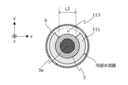
- Figure 4A is a side view showing an outline of the configuration of a mandrel having an impedancer device according to this embodiment
- Figure 4B is a cross-sectional view taken along line A-A of the mandrel having the impedancer device shown in Figure 4A.
- the impeder device 110 has an impeder core 111 and an impeder case 6.
- the mandrel 3 is provided with a roller 4 and a cutting bit 5.
- mandrel 3, roller 4, cutting bit 5, and impedance case 6 in the impedancer device 110 are similar to the mandrel 3, roller 4, cutting bit 5, and impedance case 6 in the conventional impedancer device 1 shown in FIG. 1, so a description thereof will be omitted below.
- the impedance core 111 in this embodiment is provided in a specified range on the outer periphery of the mandrel 3, and is provided to prevent the induced current generated by the induction coil from flowing around the inner periphery of the open tube and not involved in welding.
- ferromagnetic material refers to a material having an initial magnetic permeability of 1000 or more. Furthermore, when a ferromagnetic material is "insulating,” it means that its electrical conductivity is 1 ⁇ 10 ⁇ 3 S/m or less.
- Materials that can be used for the impedance core 111 in this embodiment include, for example, soft ferrite, magnetic steel, amorphous alloy, etc., which satisfy the initial magnetic permeability as described above.
- a recessed region 113 is formed with a size within a predetermined range along the extension direction of the mandrel 3 (the z-axis direction in FIG. 4A).
- the impedancer device 110 is used together with the induction coil 8.
- the range in which the recessed region 113 is formed (more specifically, the range in the z-axis direction shown in FIG. 4A) is set taking into consideration the range of influence of the magnetic flux generated by the induction coil 8, as will be explained again below.
- the size of the range in the z-axis direction in which the recessed region 113 is provided is preferably greater than 100 mm and less than or equal to the entire length of the impedance core 111.
- the size of the range in the z-axis direction in which the recessed region 113 is provided depends on the size of the induction coil 8 used, as described above, but it is preferable to design it to be, for example, the length of the induction coil 8 + 100 mm or more and the length of the induction coil 8 + 300 mm or less.
- the size of the recessed region 113 in the direction (x-axis direction in FIG. 4A) perpendicular to the elongation direction of the mandrel 3 (z-axis direction in FIG. 4A) is 10 mm or more and 1/3 the outer circumferential length of the mandrel 3 or less.
- This size roughly corresponds to the width of the opening 9a in the open tube 9 used in the manufacture of electric-resistance welded pipes.
- the recessed region 113 is formed, for example, by removing a portion of the upper part of the impedance core 111 in the thickness direction of the mandrel 3.
- the recessed region 113 according to this embodiment can be said to be a cutout portion formed by cutting out at least a portion of the impedance core 111.
- the depth of the recessed region 113 formed in the impedance core 111 is not particularly limited, and may be formed by removing a portion of the impedance core 111 to reduce the thickness of the impedance core 111, or by removing the relevant portion of the impedance core 111 to a depth that is approximately equal to the thickness (i.e., removing the entire impedance core 111 in the relevant portion). Also, it is possible to avoid installing the impedance core 111 in only the relevant portion from the beginning.
- the recessed region 113 shows a case where the impedance core 111 has been removed to a depth that is approximately equal to the thickness of the impedance core 111. In such a case, the surface of the mandrel 3 is exposed at the bottom of the recessed region 113.
- the distance between the impedance core 111 and the lower end of the end 9b of the induction coil 8 and the open tube 9 can be increased in the recessed region 113. Since the range in which the recessed region 113 is provided is an area in which high density magnetic flux is concentrated, as will be explained again below, the formation of the recessed region 113 can reduce the magnetic flux density of the impedance core 111. This makes it possible to appropriately suppress deterioration and damage to the impedance core 111 due to induction heating.
- the impedance core 111 is housed in an impedance case 6 made of, for example, a resin material, and is protected from damage due to breakage, etc.
- the impedance case 6 is preferably provided outside the impedance core 111 so that there is a gap between the impedance core 111 and the impedance case 6. In this case, it is preferable that cooling water is passed through the hollow portion of the impedance case 6 (the gap between the impedance core 111 and the impedance case 6).
- the recessed region 113 is formed by removing at least a portion of the impedance core 111 to reduce the thickness of the impedance core 111 in the recessed region 113 (or, in some cases, removing it entirely).
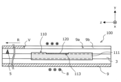
- FIG. 5 ⁇ Configuration of electric resistance welded pipe manufacturing apparatus 100>
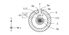
- FIGs 5, 6, and 8 are side views showing an outline of the configuration of the electric-welded pipe manufacturing apparatus 100.
- Figure 7 is a cross-sectional view taken along the line A-A of the electric-welded pipe manufacturing apparatus 100 shown in Figure 6.
- the rollers 4 provided on the mandrel 3 and the impedancer case 6 of the impedancer device 110 are omitted.
- the electric-welded pipe manufacturing apparatus 100 is an apparatus used for manufacturing electric-welded pipes, in which the ends of an open tube 9 that has been bent into a cylindrical shape while being transported in a predetermined traveling direction are melted by an induced current, and the ends are butted together and electric-welded.
- the electric-welded pipe manufacturing apparatus 100 has a forming roll group 101 for forming the desired shape of the electric-welded pipe, and an induction coil 8.
- a pair of squeeze rolls 103 are provided further downstream of the induction coil 8.
- the material for the open tube 9 is, for example, steel or stainless steel.
- the electric-welded pipe manufacturing apparatus 100 shown in FIG. 5 will be described with a particular focus on the induction coil 8 and the impedancer device 110.
- the electric welded pipe manufacturing apparatus 100 has an induction coil 8 arranged along the outer periphery of the open pipe 9, and an impedancer device 110 attached to a mandrel 3 arranged inside the open pipe 9.
- a recessed region 113 is formed in a portion of the impedance core 111 according to this embodiment.
- the region in which this recessed region 113 is formed can be explained again below, focusing on its relationship with the induction coil 8 that constitutes the electric-welded pipe manufacturing apparatus 100.
- the region in which the recessed region 113 is formed in the impedance core 111 according to this embodiment preferably corresponds to the region in which the magnetic flux density is high, as described above. Therefore, the impedance device 110 according to this embodiment is disposed inside the open tube 9 so that the recessed region 113 faces the end 9b of the open tube 9, and at least a portion of the position of the induction coil 8 is included in the recessed region 113 in the extension direction of the mandrel 3, as shown in FIG. 6, for example.
- the recessed region 113 is preferably formed to include at least a part of the range X2 directly below the induction coil 8, which is particularly affected by the magnetic flux, within the range from approximately 50 mm upstream of the induction coil 8 to the welding point V in the running direction R of the open tube 9 (hereinafter referred to as the "magnetic flux affected range X1").
- the recessed region 113 is preferably formed to a length that can include the range from a position 50 mm upstream of the induction coil 8 to a position 50 mm downstream of the induction coil 8, based on the position directly below the induction coil 8.
- the recessed area 113 may be formed in the entire magnetic flux affected range X1, as shown in FIG. 6, for example, or may be formed only in the range directly below X2 and its upstream side (the negative z-axis direction side in FIG. 8), as shown in FIG. 8.
- the impedance device 110 is configured so that the separation distance H1 between the upper end of the impedance device 110 in the portion where the recessed region 113 is formed and the lower end of the end 9b of the open tube 9 is greater than the separation distance H2 between the upper end of the impedance device 110 in the portion where the recessed region 113 is not formed (in this embodiment, for example, upstream of the recessed region 113) and the lower end of the end 9b of the open tube 9, as shown in Figures 6 and 7.
- the upper end of the impedance device 110 refers to, for example, the upper end of the exposed mandrel 3 in the portion where the recessed region 113 is formed, and refers to the upper end of the impedance core 111 in the portion where the recessed region 113 is not formed (upstream of the recessed region 113).
- the recessed area 113 is formed in the impedance core 111 so as to include at least the immediately below range X2, and therefore the distance between the impedance core 111 and the lower end of the end 9b of the induction coil 8 or the open tube 9, which is the magnetic flux generating source, is increased. This makes it possible to suppress the magnetic flux F from entering the impedance core 111, or to attenuate the magnetic flux F entering the impedance core 111, thereby suppressing the occurrence of magnetic flux saturation in the impedance core 111.
- the impedance device 110 As a result, in the impedance device 110 according to this embodiment, heat generation in the impedance core 111 is suppressed, and damage to the impedance core 111 and the impedance device 110 is suppressed, allowing stable production of electric welded pipes to continue for a long period of time. As a result, the number of times the manufacturing line is stopped due to replacement of the impedance device 110 can be reduced, and the time and cost required for maintenance of the impedance device 110 can be reduced.
- the width Y1 in the circumferential direction of the recessed region 113 in the impedance core 111 is preferably at least the same as the opening width Y2 of the opening 9a of the open tube 9 located directly above, and more preferably is larger than the opening width Y2.
- the width Y1 of the recessed region 111 is formed to be the same as the opening width Y2 of the opening 2a, or more preferably to be larger, the magnetic flux F can be more appropriately prevented from entering the impedance core 111.
- the recessed region 113 is preferably formed by removing the impedance core 111 at the upper portion of the impedance core 111 by a width Y1 that is at least equal to or greater than the opening width Y2 of the opening 9a. According to this embodiment, even if the impedance core 111 is not provided along the entire outer circumferential surface of the mandrel 3, the induced current that sneaks around from the end 9b can be appropriately suppressed.
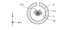
- Fig. 10 is a cross-sectional view showing a modified example of the impedancer device 110 according to the present embodiment mounted on the mandrel 3.
- the inventors have found that the induced current flowing from the end 9b to the inner periphery of the open tube 9 can be suppressed if the impedance core 111 is provided on a part of the outer periphery of the mandrel 3 (more specifically, at least the upper half of the mandrel 3).
- the impedance core 111 may be provided only on the outer periphery of the upper half of the impedance device 110 (i.e., only a region that spreads in an arc shape by 1/2 the circumference) as shown in Fig. 10. This makes it possible to appropriately suppress the induced current flowing from the end 9b to the inner periphery of the open tube 9, and also to reduce the mass and cross-sectional area of the impedance device 110.
- the modified example shown in FIG. 10 is particularly useful when the impeder device 110 according to this embodiment is applied to an electric welded pipe manufacturing apparatus that manufactures electric welded pipes with small pipe diameters. That is, when the diameter of the electric welded pipe to be manufactured is small, the diameter of the mandrel 3 provided in the open pipe 9 is also small. Therefore, unless the mass of the impeder core 111 attached to the mandrel 3 is reduced, the mandrel 3 may bend, which may cause problems such as ineffective bead cutting or reduced impeder effectiveness. Therefore, by arranging the impeder core 111 only in the part where the impeder functions effectively (in the example of FIG.
- an electromagnetic shielding material 120 for protecting the mandrel 3 may be provided on the surface of the mandrel 3 exposed by removing the impedance core 111 (in other words, the portion where the recessed region 113 in the impedance core 111 is formed).
- the electromagnetic shielding material 120 is preferably a non-magnetic material, like the mandrel 3.
- copper plate or copper mesh with insulation measures, carbon, carbon fiber, etc. can be used as the material for the electromagnetic shielding material 120.
- the electromagnetic shielding material 120 has a structure and shape that makes it difficult for the electromagnetic shielding material 120 itself to generate heat due to a magnetic field, such as a braided wire mesh with an insulating coating on the surface.
- an additional impedance may be provided on the surface of the exposed mandrel 3 (the portion where the recessed region 113 in the impedance core 111 is formed) so as to cover the recessed region 113 instead of the electromagnetic shielding material 120.
- a through hole 3b may be formed that passes vertically through the mandrel 3 over at least a portion or the entire length of the mandrel 3 exposed by forming the recessed region 113.
- FIG. 12 an example is shown in which the through hole 3b is formed when the impedance core 111 is installed in the upper half along the outer circumferential surface of the mandrel 3.
- the through hole 3b can be formed by removing the impedance core 111 from the upper and lower parts of the impedance device 110 where the through hole 3b is formed.
- the impedance core 111 down to the bottom of the mandrel 3
- damage to the impedance core 111 and the mandrel 3 can be prevented, while the induced current flowing around the inner circumference of the open tube 9 can be further suppressed.
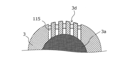
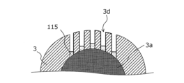
- a part of the mandrel 3 exposed by removing the impedance core 111 described above may be cut out to form a plurality of slits 3d spaced apart from each other and sandwiching a lattice 3c, which is the metal part of the mandrel 3 remaining. Therefore, in the part of the mandrel 3 where the slits 3d are formed, the lattice 3c where the mandrel 3 remains and the slits 3d where the mandrel 3 is cut out are arranged alternately along the circumferential direction of the mandrel 3.
- the slit 3d is preferably formed so as to cover at least the area directly below X2 in the running direction R of the open tube 9 where the influence of the magnetic flux is strong, and more preferably extends to a range of up to about 50 mm before and after the area directly below X2 in the running direction R.
- each of the lattice 3c which is the metal portion formed between the slits 3d, need only be large enough so that the induced current from the openings 9a and ends 9b does not form a closed circuit.
- the formation width Y3 and depth H3 of each of the lattice 3c are not particularly limited as long as they are equal to or less than twice the penetration depth of the induced current, which is determined by the frequency of the current and the electrical conductivity and initial permeability of the mandrel 3.
- the penetration depth of the induced current can be calculated based on the following formula (1).
- ⁇ 5.03 ⁇ ( ⁇ / ⁇ f) 0.5 ...Formula (1)
- ⁇ Penetration depth (unit: cm)
- ⁇ specific resistivity of mandrel 3 (i.e., the reciprocal of electrical conductivity) (unit: ⁇ cm)
- ⁇ initial permeability of mandrel 3
- f frequency of current (unit: Hz) It is.
- the specific resistivity of the mandrel 3 is approximately 20 ⁇ cm at room temperature and approximately 128 ⁇ cm at 1000°C. Since stainless steel, a non-magnetic material, is often used as the material for the mandrel 3, the initial permeability of the mandrel 3 can be treated as 1. If the mandrel 3 is made of a magnetic material, the initial permeability changes depending on the strength of the magnetic field. For example, if the mandrel 3 is made of steel, it will exhibit a value of approximately 20 to 1000 when heated.
- the formation width Y3 of the lattice 3c is the remaining width in the circumferential direction of the mandrel 3 in a cross-sectional view, as shown in FIG. 14, and can also be said to be the formation interval of the slits 3d. Therefore, in this embodiment, the formation interval Y3 of the slits 3d is not required to be uniform as long as it is equal to or less than twice the penetration depth of the induced current and does not form a closed circuit.
- the induced currents that enter each slit 3d from the openings 9a and ends 9b and flow along the surface of the lattice 3c are offset and attenuated by being in opposite phase to each other on the surfaces of adjacent lattices 3c.
- damage to the impedance core 111 and the mandrel 3 caused by the induced currents can be better prevented, while the induced currents that flow around the inner circumference of the open tube 9 can be better suppressed.
- the formation of the slits 3d may cause the cooling water to leak out of the mandrel 3. If cooling water is passed through the inside of the mandrel 3 and it is desired to prevent the cooling water from leaking out, the slits 3d may be sealed with a sealing material 115 that does not cause dielectric loss, such as an adhesive or resin, as shown as an example in FIG. 15A.
- the sealing material 115 does not need to completely fill the entire length of the depth H3 of the slits 3d, and it is sufficient that the sealing material 115 is present in at least a portion of the depth H3 of the slits 3d, as shown in FIGS. 15B and 15C, to prevent the cooling water from leaking out from the inside.
- an insulating film/layer or the electromagnetic shielding material 120 shown in FIG. 11 may be provided along at least one of the outer peripheral surface or inner peripheral surface of the mandrel 3, in other words, to block at least one of the upper and lower parts of the slit 3d.
- At least one of a sealing material 115, an insulating film/layer, or an electromagnetic shielding material 120 may be provided in the portion of the mandrel 3 where the slit 3d is formed, as a sealing member to prevent the cooling water from leaking out from inside the mandrel 3.
- the recessed region 113 is formed by removing a part of the impedance core 111 so as to reduce the thickness of the impedance core, or by completely removing the impedance core 111, but the method of forming the recessed region 113 is not limited to such examples.
- a second embodiment of the present invention will be described below.
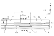
- FIGS. 16 and 17 are side views showing an outline of the configuration of an electric welded pipe manufacturing apparatus 200 having an impeder device 210 according to this embodiment attached to a mandrel 3. Note that in the configuration of the electric welded pipe manufacturing apparatus 200, elements having substantially the same functional configuration as the configuration of the electric welded pipe manufacturing apparatus 1 or the electric welded pipe manufacturing apparatus 100 are designated by the same reference numerals, and duplicated explanations will be omitted.
- an electric-welded pipe manufacturing apparatus 200 has a group of forming rolls (not shown in FIG. 16), an induction coil 8 provided along the outer periphery of an open pipe 9, and an impedancer device 210 provided inside the open pipe 9, similar to the electric-welded pipe manufacturing apparatus 100 shown in FIG. 5.
- the impedancer device 210 also has an impedancer core 211.
- a recessed region 213 is formed similarly to the recessed region 113 according to the first embodiment. Specifically, the recessed region 213 is formed in the running direction R of the open tube 9 so as to include at least a part of the magnetic flux affected range X1, the range X2 directly below the induction coil 8, which is particularly strongly affected by the magnetic flux.
- the recessed region 213 is formed, for example, by bending the mandrel 3 and the impedance core 211 downward within an arbitrary range in the magnetic flux affected range X1, as shown in FIG. 16.
- the recessed region 213 formed in the impedance core 211 can be rephrased as the curved region of the impedance core 211.
- the depth of the recessed region 213, i.e., the curvature depth of the impedance core 211, is set, as an example, to be approximately equal to the thickness of the impedance core 211, similar to the recessed region 113 in the first embodiment.
- the impedance core 211 is curved to form a recessed region 213 within a range including at least a portion of the range X2 directly below the induction coil 8, so that the distance from the induction coil 8 as a magnetic flux source or the lower end of the end 9b becomes larger than that on the upstream side, and the magnetic flux entering the impedance core 211 can be attenuated.
- This also makes it possible to prevent the impedance core 211 from causing magnetic flux saturation, thereby suppressing heat generation in the impedance core 211 and suppressing damage to the impedance core 211 and the impedance device 210, allowing stable production of electric welded pipes to continue for a long period of time. As a result, the number of times the production line is stopped due to replacement of the impedance device 210 can be reduced, thereby reducing the time and cost required for maintenance of the impedance device 210.
- the recessed region 213 can be formed without removing the impeder core 211. Therefore, according to this embodiment, it is possible to enjoy the same impedance effect as a conventional impeder device, and furthermore, damage to the impeder device 210, particularly the impeder core 211, can be suppressed.
- the impedance core 211 may be provided only in the upper half of the outer peripheral surface of the impedance device 210, in an area that extends along an arc of 1/2 the circumference.
- the mandrel 3 and only the upper surface of the impedance core 211 may be curved to form the recessed region 213, as shown in FIG. 17, for example.
- the configuration of the impedancer device 210 according to the second embodiment of the present invention as described above can be appropriately applied to the impedancer device 110 according to the first embodiment of the present invention.
- an open pipe made of ordinary steel with a diameter of ⁇ 216.3 mm and a thickness of 6 mm was heated by placing an induction coil with a width of 150 mm in the longitudinal direction, 150 mm upstream from the welding point, and used electromagnetic field analysis to determine the difference in magnetic flux density due to differences in the impedance device configuration.
- the induction coil was placed with a gap of 5 mm from the open pipe, and a high-frequency current of 4000 [A] with a frequency of 300 kHz was passed through it.
- the impedance core was assumed to be made of soft ferrite with a thickness of 10 mm, a circumferential width of 15 mm, and a longitudinal length of 50 mm (relative permeability 1500, saturation magnetic flux density 0.45 T), with multiple soft ferrite pieces attached adjacent to each other with an adhesive to the outer circumference of a SUS304 mandrel with a diameter of ⁇ 140 mm.
- the installation conditions for the impedance core were as follows:
- Example 1 of the invention In the present invention example 1, the electromagnetic field analysis was performed on the situation shown in Fig. 8 in the first embodiment.
- a recessed region with a width of 16 mm in the x-axis direction in Fig. 8 was formed in a range from 50 mm upstream of the induction coil to 250 mm toward the welding point side, and the mandrel was exposed.
- an impeder was installed in this recessed region, and the distance from the upper end of the impeder to the open tube was 23 mm, and the distance from the impeder device surface (i.e., from the impeder core) to the open tube in other parts was 13 mm.
- This assumption corresponds to the case where the impeder is installed in the region closer to point V in the region within the range of length X1 and outside the range of length X2 in Fig. 8.
- Example 2 of the invention In Example 2 of the present invention, an electromagnetic field analysis was performed on the situation shown in Fig. 6 in the first embodiment.
- a recessed region with a width of 16 mm in the x-axis direction in Fig. 6 was formed in the range from 50 mm upstream of the induction coil to the downstream end of the impedance core (i.e., the entire range affected by the magnetic flux), and the mandrel was exposed.
- the distance from the mandrel to the open tube was 33 mm, and the distance from the impedance device surface (i.e., from the impedance core) to the open tube in other locations was 13 mm.
- Example 3 of the invention In Example 3 of the present invention, as shown in FIG. 10 of the first embodiment, a copper mesh having a thickness of 5 mm was provided as an electromagnetic shielding material on the exposed mandrel in Example 2 of the present invention.
- Comparative Example 1 is a conventional electric resistance welded pipe manufacturing apparatus in which no recessed region is formed as shown in Figures 2 and 3, that is, the distance from the impedancer device to the open pipe is fixed at 13 mm.
- Table 1 shows the maximum magnetic flux density and the mandrel heat generation ratio as a result of the electromagnetic field analysis for each of the present inventions 1 to 3 and the comparative example. Note that the mandrel heat generation ratio in the table is the ratio of the heat generation amount of each invention example when the heat generation amount of the comparative example is set to 1.0.
- the maximum magnetic flux density of the impedance core was 0.62 T, a value that greatly exceeded the saturation magnetic flux density of 0.45 T.
- the maximum magnetic flux density of the impedance core was 0.43 T, which was below the saturation magnetic flux density of the impedance core.
- Example 2 of the present invention in which a recessed region was formed up to the downstream end of the impedance core, the maximum magnetic flux density was 0.42 T, which was below the saturation magnetic flux density of the impedance core.
- Example 1 of the present invention when covered with an impedance as in Example 1 of the present invention, only a small amount of magnetic flux entered the mandrel, but in Example 2 of the present invention, the impedance was eliminated, so the magnetic flux entered the mandrel directly, causing the mandrel to heat up, resulting in a 12% increase in the total heat generation ratio.
- the amount of heat generated increased, it was not to a level that would cause damage, and the magnetic flux density of the impedance was reduced, enabling stable production.
- Example 3 of the present invention in which a copper mesh electromagnetic shielding material was provided on the exposed mandrel, the maximum magnetic flux density of the impedance core was 0.42 T, which is equivalent to the result of Example 2 of the present invention, and the total heat generation ratio was also suppressed to the same level as Example 1 of the present invention.
- the present invention is useful for electric-resistance welded pipe welding equipment that bends a traveling metal strip into a cylindrical shape, inductively heats it, and welds both end surfaces of the metal strip using the current induced in the metal strip.
- Electric-resistance welded pipes manufactured in this way are used for pipes that require weight reduction, such as oil country pipes and pipes for two- and four-wheeled vehicles.
Landscapes
- Engineering & Computer Science (AREA)
- Mechanical Engineering (AREA)
- General Induction Heating (AREA)
Priority Applications (2)
| Application Number | Priority Date | Filing Date | Title |
|---|---|---|---|
| JP2025506499A JPWO2024190040A1 (https=) | 2023-03-16 | 2023-12-25 | |
| EP23927642.1A EP4647201A1 (en) | 2023-03-16 | 2023-12-25 | Mandrel equipped with impeder device, electric resistance welded tube manufacturing device, and manufacturing method of electric resistance welded tube |
Applications Claiming Priority (2)
| Application Number | Priority Date | Filing Date | Title |
|---|---|---|---|
| JP2023-042018 | 2023-03-16 | ||
| JP2023042018 | 2023-03-16 |
Publications (1)
| Publication Number | Publication Date |
|---|---|
| WO2024190040A1 true WO2024190040A1 (ja) | 2024-09-19 |
Family
ID=92754649
Family Applications (1)
| Application Number | Title | Priority Date | Filing Date |
|---|---|---|---|
| PCT/JP2023/046526 Ceased WO2024190040A1 (ja) | 2023-03-16 | 2023-12-25 | インピーダー装置を備えたマンドレル、電縫管製造装置及び電縫管の製造方法 |
Country Status (3)
| Country | Link |
|---|---|
| EP (1) | EP4647201A1 (https=) |
| JP (1) | JPWO2024190040A1 (https=) |
| WO (1) | WO2024190040A1 (https=) |
Citations (7)
| Publication number | Priority date | Publication date | Assignee | Title |
|---|---|---|---|---|
| JPS5236721U (https=) * | 1975-09-09 | 1977-03-15 | ||
| JPS5818690U (ja) * | 1981-07-28 | 1983-02-04 | ティーディーケイ株式会社 | 電縫管製造装置用インピ−ダコア |
| JPS58221681A (ja) * | 1982-06-18 | 1983-12-23 | Sumitomo Metal Ind Ltd | 電縫管の製造方法及びインピ−ダ |
| JPS598869U (ja) | 1982-07-08 | 1984-01-20 | セイレイ工業株式会社 | 動力運搬車における機体連結部構造 |
| JPS6296984U (https=) * | 1985-12-03 | 1987-06-20 | ||
| JP2001062572A (ja) | 1999-08-27 | 2001-03-13 | Sumitomo Metal Ind Ltd | インピーダー装置 |
| JP2007210026A (ja) * | 2006-02-13 | 2007-08-23 | Tdk Corp | インピーダコア |
-
2023
- 2023-12-25 JP JP2025506499A patent/JPWO2024190040A1/ja active Pending
- 2023-12-25 EP EP23927642.1A patent/EP4647201A1/en active Pending
- 2023-12-25 WO PCT/JP2023/046526 patent/WO2024190040A1/ja not_active Ceased
Patent Citations (7)
| Publication number | Priority date | Publication date | Assignee | Title |
|---|---|---|---|---|
| JPS5236721U (https=) * | 1975-09-09 | 1977-03-15 | ||
| JPS5818690U (ja) * | 1981-07-28 | 1983-02-04 | ティーディーケイ株式会社 | 電縫管製造装置用インピ−ダコア |
| JPS58221681A (ja) * | 1982-06-18 | 1983-12-23 | Sumitomo Metal Ind Ltd | 電縫管の製造方法及びインピ−ダ |
| JPS598869U (ja) | 1982-07-08 | 1984-01-20 | セイレイ工業株式会社 | 動力運搬車における機体連結部構造 |
| JPS6296984U (https=) * | 1985-12-03 | 1987-06-20 | ||
| JP2001062572A (ja) | 1999-08-27 | 2001-03-13 | Sumitomo Metal Ind Ltd | インピーダー装置 |
| JP2007210026A (ja) * | 2006-02-13 | 2007-08-23 | Tdk Corp | インピーダコア |
Non-Patent Citations (1)
| Title |
|---|
| See also references of EP4647201A1 |
Also Published As
| Publication number | Publication date |
|---|---|
| JPWO2024190040A1 (https=) | 2024-09-19 |
| EP4647201A1 (en) | 2025-11-12 |
Similar Documents
| Publication | Publication Date | Title |
|---|---|---|
| CN102548704B (zh) | 电焊管焊接装置 | |
| US4197441A (en) | High frequency induction welding with return current paths on surfaces to be heated | |
| KR101614668B1 (ko) | 전봉관 용접 장치 | |
| JPS5952028B2 (ja) | 電縫管製造用インピ−ダ | |
| KR101296972B1 (ko) | 전봉관 용접 장치 | |
| WO2024190040A1 (ja) | インピーダー装置を備えたマンドレル、電縫管製造装置及び電縫管の製造方法 | |
| JP6097784B2 (ja) | 電縫管溶接装置 | |
| JP6834724B2 (ja) | 電縫管溶接装置 | |
| JP6436267B2 (ja) | 電縫管溶接装置及び電縫管溶接方法 | |
| JP4632428B2 (ja) | 鋼管の高周波誘導加熱造管方法 | |
| JP7541275B1 (ja) | インピーダーシート、電縫管製造装置のマンドレル及び電縫管の製造方法 | |
| JPS6124373Y2 (https=) | ||
| WO2024190039A1 (ja) | インピーダーシート、電縫管製造装置のマンドレル及び電縫管の製造方法 | |
| JP2014229486A (ja) | 誘導加熱装置 | |
| JPH1076372A (ja) | オープン管エッジ部予熱装置 | |
| JP2007210026A (ja) | インピーダコア | |
| JP2018176193A (ja) | 電縫管溶接装置 | |
| WO2019216065A1 (ja) | 電縫溶接用給電コイル及びこれを用いた造管設備 | |
| JP2006272423A (ja) | 鋼管の高周波誘導加熱造管方法 | |
| JPWO2024190040A5 (https=) |
Legal Events
| Date | Code | Title | Description |
|---|---|---|---|
| 121 | Ep: the epo has been informed by wipo that ep was designated in this application |
Ref document number: 23927642 Country of ref document: EP Kind code of ref document: A1 |
|
| WWE | Wipo information: entry into national phase |
Ref document number: 2025506499 Country of ref document: JP |
|
| WWE | Wipo information: entry into national phase |
Ref document number: 2501005854 Country of ref document: TH |
|
| NENP | Non-entry into the national phase |
Ref country code: DE |
|
| WWP | Wipo information: published in national office |
Ref document number: 2023927642 Country of ref document: EP |