WO2024189897A1 - マルチコア光ファイバ、及び、マルチコア光ファイバの設計方法 - Google Patents
マルチコア光ファイバ、及び、マルチコア光ファイバの設計方法 Download PDFInfo
- Publication number
- WO2024189897A1 WO2024189897A1 PCT/JP2023/010317 JP2023010317W WO2024189897A1 WO 2024189897 A1 WO2024189897 A1 WO 2024189897A1 JP 2023010317 W JP2023010317 W JP 2023010317W WO 2024189897 A1 WO2024189897 A1 WO 2024189897A1
- Authority
- WO
- WIPO (PCT)
- Prior art keywords
- core
- cores
- line
- mode field
- field diameter
- Prior art date
- Legal status (The legal status is an assumption and is not a legal conclusion. Google has not performed a legal analysis and makes no representation as to the accuracy of the status listed.)
- Ceased
Links
Images


Classifications
-
- G—PHYSICS
- G02—OPTICS
- G02B—OPTICAL ELEMENTS, SYSTEMS OR APPARATUS
- G02B6/00—Light guides; Structural details of arrangements comprising light guides and other optical elements, e.g. couplings
- G02B6/02—Optical fibres with cladding with or without a coating
- G02B6/02042—Multicore optical fibres
-
- G—PHYSICS
- G02—OPTICS
- G02B—OPTICAL ELEMENTS, SYSTEMS OR APPARATUS
- G02B6/00—Light guides; Structural details of arrangements comprising light guides and other optical elements, e.g. couplings
- G02B6/02—Optical fibres with cladding with or without a coating
- G02B6/036—Optical fibres with cladding with or without a coating core or cladding comprising multiple layers
- G02B6/03616—Optical fibres characterised both by the number of different refractive index layers around the central core segment, i.e. around the innermost high index core layer, and their relative refractive index difference
- G02B6/03638—Optical fibres characterised both by the number of different refractive index layers around the central core segment, i.e. around the innermost high index core layer, and their relative refractive index difference having 3 layers only
- G02B6/0365—Optical fibres characterised both by the number of different refractive index layers around the central core segment, i.e. around the innermost high index core layer, and their relative refractive index difference having 3 layers only arranged - - +
Definitions
- This disclosure relates to a multi-core optical fiber and a method for designing a multi-core optical fiber.
- Patent Document 1 and Non-Patent Document 1 disclose MCFs that employ a trench-type refractive index distribution that has a strong light confinement effect.
- Patent Document 2 discloses an MCF that employs a step-index refractive index distribution that is suitable for mass production.
- Patent Document 3 discloses an MCF for long-distance transmission that reduces crosstalk by limiting the transmission wavelength band of the single-mode operation region of each core to 1.53 ⁇ m to 1.625 ⁇ m in the C and L bands, or 1.46 ⁇ m to 1.625 ⁇ m in the S, C, and L bands.
- the size of the mode field diameter (MFD), which represents the spread of the optical intensity distribution at the cross section of the optical signal, is limited in order to suppress crosstalk and excess loss due to the design.
- MFD mode field diameter
- the MFD is small, at around 9 ⁇ m to 10 ⁇ m, and the loss coefficient is large, at 0.155 dB/km to 0.18 dB/km.
- This disclosure has been made in consideration of the above circumstances, and the purpose of this disclosure is to provide a multi-core optical fiber and a design method for a multi-core optical fiber that can expand the mode field diameter while ensuring the suppression of crosstalk and excess loss in design.
- the multi-core optical fiber comprises a plurality of cores arranged in a square lattice or in a row along the longitudinal direction of the multi-core optical fiber, a plurality of first cladding regions surrounding the plurality of cores and having a lower refractive index than the surrounding cores, a plurality of second cladding regions surrounding the plurality of first cladding regions and having a lower refractive index than the surrounding first cladding regions, and a third cladding region surrounding the plurality of second cladding regions and having a lower refractive index than the plurality of cores, and the mode field diameter and core spacing of the plurality of cores are the mode field diameter and core spacing corresponding to the region surrounded by the intersection points of a first line indicating the upper limit of the core spacing at which the excess loss of the cores is kept below a predetermined value, a second line indicating the lower limit of the core spacing at which the crosstalk between the cores is kept below a predetermined value, and a third
- a multi-core optical fiber comprises a plurality of cores arranged in a square lattice pattern or in a row along the longitudinal direction of the multi-core optical fiber, a plurality of first cladding regions surrounding the plurality of cores respectively and having a lower refractive index than the surrounding cores, a plurality of second cladding regions surrounding the plurality of first cladding regions respectively and having a lower refractive index than the surrounding first cladding regions, and a third cladding region surrounding the plurality of second cladding regions and having a lower refractive index than the plurality of cores, the diameter of the third cladding region being 125 ⁇ 1 ⁇ m, the cutoff wavelength being 1.53 ⁇ m or less, the mode field diameter of the plurality of cores at a wavelength of 1.55 ⁇ m being 9.5 ⁇ m to 15.0 ⁇ m, and the core spacing of the plurality of cores being 33 ⁇ m to 50 ⁇ m.
- a method for designing a multi-core optical fiber includes a plurality of cores arranged in a square lattice or in a row along the longitudinal direction of the multi-core optical fiber, a plurality of first cladding regions surrounding the plurality of cores and having a lower refractive index than the surrounding cores, a plurality of second cladding regions surrounding the plurality of first cladding regions and having a lower refractive index than the surrounding first cladding regions, and a third cladding region surrounding the plurality of second cladding regions and having a lower refractive index than the plurality of cores, and a computer calculates, as the mode field diameter and core spacing of the plurality of cores, the mode field diameter and core spacing corresponding to a region surrounded by the intersection points of a first line indicating the upper limit of the core spacing at which the excess loss of the cores is equal to or less than a predetermined value in a graph showing the relationship between the mode field diameter and the core spacing, a
- This disclosure provides technology that can expand the mode field diameter while ensuring the suppression of crosstalk and excess loss due to design.
- FIG. 1 is a diagram showing a cross-sectional structure of an MCF according to the first embodiment.
- FIG. 2 is a diagram showing the refractive index profile of the region near the core.
- FIG. 3 is a diagram showing the relationship between the MFD and the increase in Rayleigh scattering loss.
- FIG. 4 is a diagram showing the relationship between the same-directional crosstalk and the bidirectional crosstalk.
- FIG. 5 is a diagram showing the relationship between codirectional crosstalk and wavelength.
- FIG. 6 is a diagram showing the relationship between the MFD and the core spacing.
- FIG. 7A is a diagram showing the relationship between MFD and core spacing for ⁇ 1 .
- FIG. 7B is a graph showing the relationship between MFD and core spacing for ⁇ 1 .
- FIG. 8A is a diagram showing the relationship between MFD and core spacing for ⁇ 1 .
- FIG. 8B is a diagram showing the relationship between MFD and core spacing for ⁇ 1 .
- FIG. 9A is a diagram showing the relationship between MFD and core spacing for ⁇ 1 .
- FIG. 9B is a graph showing the relationship between MFD and core spacing for ⁇ 1 .
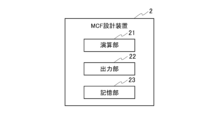
- FIG. 10 is a diagram showing a functional block configuration of the MCF design device.
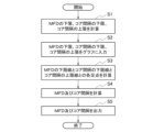
- FIG. 11 is a diagram showing a method for designing an MCF.
- FIG. 12 is a diagram showing a cross-sectional structure of the MCF according to the second embodiment.
- FIG. 13 is a diagram showing a hardware configuration of the MCF design device.
- FIG. 1 is a diagram showing a cross-sectional structure of an MCF according to a first embodiment.
- the MCF 1 is an MCF with a standard cladding diameter of about 125 ⁇ 1 ⁇ m.
- the MCF 1 includes four cores 10 arranged in a square lattice shape along the longitudinal direction (extension direction) of the paper surface, four first cladding regions 11 surrounding each of the four cores 10, four second cladding regions 12 surrounding each of the four first cladding regions 11, and one third cladding region 13 surrounding all of the second cladding regions 12.
- the diameter of the third cladding region 13 is about 125 ⁇ 1 ⁇ m.
- FIG. 2 is a diagram showing the refractive index distribution in the region near the core.
- the horizontal axis is the short-side direction of the MCF 1 (the radial direction passing through the center of the core 10), and the vertical axis is the relative refractive index difference.
- the refractive index of the first cladding region 11 is lower than that of the core 10.
- the refractive index of the second cladding region 12 is lower than that of the first cladding region 11.
- the refractive index of the third cladding region 13 is lower than that of the four cores 10.
- Each core 10 has such a trench-type refractive index distribution or a refractive index distribution equivalent thereto.
- the refractive index distributions of each core 10 are approximately identical to each other.
- the radius of the core 10 is a.
- the radius of the inner diameter of the second cladding region 12 is a1 .
- the radius of the outer diameter of the second cladding region 12 is a2 .
- the absolute value of the relative refractive index difference between the core 10 and the first cladding region 11 is ⁇ .
- the absolute value of the relative refractive index difference between the core 10 and the second cladding region 12 is ⁇ 1 .
- the relative refractive index difference between the core 10 and the third cladding region 13 may be equal to ⁇ or may be different from ⁇ .
- the transmission wavelength band is 1.53 ⁇ m to 1.625 ⁇ m for the C and L bands, or 1.46 ⁇ m to 1.625 ⁇ m for the S, C, and L bands.
- the material of the core 10 is pure silica glass.
- Figure 3 shows the relationship between MFD ( ⁇ m) and the increase in Rayleigh scattering loss (dB/km) at this time. It can be seen that the increase in Rayleigh scattering loss decreases as the MFD increases. This is thought to be because the electric field components contained in the core 10, which is pure silica glass, increase as the MFD increases. It is also thought to be because the electric field components leaking from the core 10 to the first cladding region 11 or to its outside decrease, reducing scattering loss and structural irregularity loss at the interface between the core and cladding.
- MFD 10.8 ⁇ m can be used as the lower limit of the MFD that keeps the increase in Rayleigh scattering loss to 0.003 dB/km or less.
- Figure 4 is a characteristic diagram showing the crosstalk relationship between unidirectional transmission, in which optical signals are transmitted in the same direction between adjacent cores, and bidirectional transmission, in which optical signals are transmitted in opposite directions.
- the horizontal axis is unidirectional crosstalk (dB/1 km) after 1 km of transmission, and the vertical axis is bidirectional crosstalk (dB/80 km) after 80 km of transmission.
- bidirectional transmission has the characteristic that it can reduce crosstalk more than unidirectional transmission. Therefore, as shown in Figure 4, the crosstalk per 80 km in bidirectional transmission and the crosstalk per km in unidirectional transmission are roughly equivalent to each other. Note that the crosstalk relationship between unidirectional transmission and bidirectional transmission does not depend on the wavelength.
- crosstalk at the receiving end during bidirectional transmission is reduced to about -25 dB.
- the bidirectional crosstalk needs to be approximately -35 dB and -45 dB per 80 km, respectively.
- the corresponding codirectional crosstalk needs to be approximately -35 dB and -45 dB per 1 km, as shown in Figure 4.
- FIG. 5 is a diagram showing an example of codirectional crosstalk in MCF 1.
- the horizontal axis is wavelength ( ⁇ m) and the vertical axis is codirectional crosstalk (dB/1 km) after 1 km transmission.
- MCF Design Method Calculation Method of MFD and Core Spacing
- Fig. 6 shows the relationship between MFD and core spacing.
- the horizontal axis is MFD ( ⁇ m) at a wavelength of 1.55 ⁇ m
- the vertical axis is core spacing ( ⁇ m).
- a1 /a 2.0
- a2 /a 3.0
- ⁇ 1 0.6%
- ⁇ 1.625 ⁇ m.
- the lower limit of the MFD for making the increase in Rayleigh scattering loss ⁇ R 0.003 dB/km or less for the core 10 made of pure silica glass is the third line L3.
- the dependency of the increase in Rayleigh scattering loss ⁇ R on the cutoff wavelength ⁇ c is sufficiently small.
- intersections A, B, C, A', B', and C' are the structural conditions of MCF1.
- the MFD and core spacing corresponding to the region surrounded by structural conditions A, B, and C are calculated (set) as the MFD and core spacing of MCF1 when the cutoff wavelength is 1.53 ⁇ m or less. Also, the MFD and core spacing corresponding to the region surrounded by structural conditions A', B', and C' are calculated (set) as the MFD and core spacing of MCF1 when the cutoff wavelength is 1.46 ⁇ m or less.
- the size of the region is smaller than when the cutoff wavelength is 1.53 ⁇ m or less, so the MFD and core spacing are smaller.
- this is preferable from the standpoint of guaranteeing single-mode operation in the S band, expanding the wavelength band in use, and ensuring the stability of Raman amplification for the C band.
- the MFD and core spacing are set within the area surrounded by structural conditions A, B, and C, or structural conditions A', B', and C', so the mode field diameter can be expanded while ensuring the suppression of crosstalk and excess loss in the design.
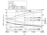
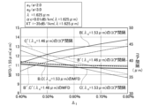
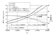
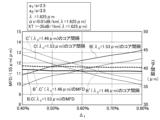
- Figures 7A, 7B, 8A, 8B, 9A, and 9B The horizontal axis is ⁇ 1 , the left vertical axis is MFD ( ⁇ m) at a wavelength of 1.55 ⁇ m, and the right vertical axis is core spacing ( ⁇ m).
- Figures 7A, 8A, and 9A are the MFD and core spacing of structural conditions A and A'.
- 7B, 8B, and 9B show the MFD and core spacing for the structural conditions B and B' and the structural conditions C and C'.
- the MFD and core spacing are calculated (set) using the maximum and minimum values among the values of the changed structural conditions A, B, C, A', B', and C'. From Figures 7A, 7B, 8A, 8B, 9A, and 9B, when the cutoff wavelength is 1.53 ⁇ m or less, the MFD at a wavelength of 1.55 ⁇ m is about 9.5 ⁇ m to about 15.0 ⁇ m, and the core spacing is about 33 ⁇ m to about 50 ⁇ m.
- the set value for the MFD is within the range of 9.5 ⁇ m to 15.0 ⁇ m specified in the international standard for single-mode optical fiber, ITU-T G.654 (Category D).
- MCF design method and design flow (MFD and core spacing calculation flow) 10 is a diagram showing a functional block configuration of the MCF design device 2.
- the MCF design device 2 is a computer for designing the MCF 1, and includes a calculation unit 21 that calculates the MFD and core spacing, an output unit 22 that outputs the calculated MFD and core spacing, and a storage unit 23 that stores various data required for calculating the MFD and core spacing.
- Figure 11 shows the calculation flow for MFD and core spacing.
- the calculation unit 21 calculates the lower limit of MFD that keeps the increase in Rayleigh scattering loss below a predetermined level, the lower limit of core spacing that keeps crosstalk below a predetermined level, and the upper limit of core spacing that keeps the design excess loss below a predetermined level (step S1).
- the calculation unit 21 inputs the upper limit of the core spacing, the lower limit of the core spacing, and the lower limit of the MFD calculated in step S1 into a graph showing the relationship between MFD and core spacing (step S2).
- the calculation unit 21 calculates, for each cutoff wavelength, the intersection A (A') between the first line L1 indicating the upper limit of the core spacing and the second line L2 indicating the lower limit of the core spacing, the intersection B (B') between the first line L1 and the third line L3 indicating the lower limit of the MFD, and the intersection C (C') between the second line L2 and the third line L3 (step S3).
- the calculation unit 21 calculates the MFD and core spacing corresponding to the region surrounded by the intersections A, B, and C (A ' , B', C') in the graph as the MFD and core spacing of MCF1 (step S4).
- the calculation unit 21 changes one or more of a1/a, a2 /a, and ⁇ 1 , and calculates the MFD and core spacing of MCF1 using the maximum and minimum values among the changed values of the intersections A, B, and C.
- the output unit 22 outputs the MFD and core spacing of MCF1 (step S5).
- a W , B W , and C W are the MFDs of structural conditions A, B, and C, respectively.
- a ⁇ , B ⁇ , and C ⁇ are the core spacings of structural conditions A, B, and C, respectively.
- K ⁇ 1 to K ⁇ 3 are proportionality constants.
- K ⁇ 1 to K ⁇ 3 for the structural conditions A, B, and C are as shown in Table 1.
- Equation (2) The relationship between MFD and core spacing and ⁇ 1 depends on a1 /a as shown in Figures 7A, 7B, 8A, 8B, 9A, and 9B, so K ⁇ 1 to K ⁇ 3 for structural conditions A, B, and C can be approximated by equation (2), respectively.
- K 1a to K 1c , K 2a to K 2c , and K 3a to K 3c are proportionality constants.
- K 1a to K 1c , K 2a to K 2c , and K 3a to K 3c for the structural conditions A, B, and C are as shown in Table 2.
- A' W , B' W , and C' W are the MFDs of the structural conditions A', B', and C', respectively.
- A' ⁇ , B' ⁇ , and C' ⁇ are the core spacings of the structural conditions A', B', and C', respectively.
- K ⁇ 1 to K ⁇ 3 of the structural conditions A', B', and C' are shown in Table 3.
- K ⁇ 1 to K ⁇ 3 of the structural conditions A', B', and C' are the same as those in formula (2).
- K 1a to K 1c , K 2a to K 2c , and K 3a to K 3c of the structural conditions A', B', and C' are shown in Table 4.
- the mode field diameter and core spacing corresponding to the region after changing one or more of the ratio of the inner radius of the second cladding region to the core radius, the ratio of the outer radius of the second cladding region to the core radius, and the relative refractive index difference between the core and the second cladding region are calculated as the MFD of the core and the core spacing, so that a technology can be provided that can appropriately expand the MFD while appropriately ensuring the suppression of crosstalk and excess loss in design.
- the MFD and core spacing are calculated using the approximation of formula (1) or formula (3), so that a technology can be provided that can more appropriately and simply increase the MFD while more appropriately and simply ensuring the suppression of crosstalk and excess loss in the design.
- the mode field diameter at a wavelength of 1.55 ⁇ m is set to 9.5 ⁇ m to 15.0 ⁇ m, and the core spacing is set to 33 ⁇ m to 50 ⁇ m, so that a technology can be provided that can more appropriately and simply increase the MFD while more appropriately and simply ensuring the suppression of crosstalk and excess loss in the design.
- Fig. 12 is a diagram showing a cross-sectional structure of the MCF 1 according to the second embodiment.
- the MCF 1 is an MCF having a standard cladding diameter of about 125 ⁇ 1 ⁇ m, as in the first embodiment.
- the two cores 10 have the trench-type refractive index profile shown in Fig. 2 or a refractive index profile equivalent thereto.
- the refractive index profiles of the cores 10 are approximately the same as each other.
- the two-core MCF1 we consider a structure that simultaneously suppresses the design excess loss, crosstalk, and Rayleigh scattering loss, as in Figure 6.
- the increase in crosstalk which is the loss between adjacent cores
- the increase in Rayleigh scattering loss which is the loss in each core
- an area surrounded by three intersections A, B, and C or an area surrounded by three intersections A', B', and C' is obtained.
- the design excess loss is related by the cladding thickness, which is defined as the shortest distance from the center of each core to the cladding end, as given by equation (4) for an MCF1 with a standard cladding diameter, where the cladding thickness is OCT, the core spacing is ⁇ , and the cladding diameter is D.
- the 2 in ⁇ 2 is the identifier for a 2-core structure.
- the 4 in ⁇ 4 is the identifier for a 4-core structure.
- the MFD and core spacing are calculated using the approximation of formula (5) or formula (6), so that a technology can be provided that can more appropriately and simply increase the MFD while more appropriately and simply ensuring the suppression of crosstalk and excess loss in the design.
- a standard optical fiber is coated with a coating layer such as a UV resin so that the cladding has a cladding diameter of 125 ⁇ m and the diameter is about 250 ⁇ 15 ⁇ m. Therefore, the MCF 1 of the first and second embodiments may also be coated with a coating layer so that the diameter size is the same. This is preferable because it is sized to fit existing optical cables, connector interfaces, and the like that have the same diameter size.
- the fiber may be coated to meet the specifications of the international standard for single-mode optical fibers, IEC 60793-2-50.
- the fiber may be coated to a diameter of approximately 200 ⁇ 20 ⁇ m. This is preferable, as it allows for a dramatic expansion of the overall number of cores, density, and transmission capacity.
- the bending loss of the MCF1 at a wavelength of 1.625 ⁇ m and a bending radius of 30 mm meets the bending loss conditions defined in the international standards for single-mode optical fibers, "ITU-T G.652" and “ITU-T G.654 (Category E),” specifically, be 0.1 dB/100 turns or less.
- the diameter of the MCF1 coated with the coating layer is set to approximately 250 ⁇ 15 ⁇ m or 200 ⁇ 20 ⁇ m, making it possible to provide an MCF1 that meets international standards, etc.
- the present disclosure is not limited to the above-described embodiment. It is also possible to combine the first to third embodiments.
- the present disclosure allows for various modifications within the scope of the gist of the disclosure.
- the cores 10 may be a plurality of cores arranged in a square lattice or in a line along the longitudinal direction of the multi-core optical fiber. There may be a total of nine cores arranged in a 3 ⁇ 3 square lattice, or three cores arranged in a line.
- the MCF design device 2 described above can be realized, for example, as shown in FIG. 13, by using a general-purpose computer system equipped with a CPU 901, memory 902, storage 903, communication device 904, input device 905, and output device 906.
- the memory 902 and storage 903 are storage devices.
- the CPU 901 executes a predetermined program loaded onto the memory 902, thereby realizing each function of the MCF design device 2.
- the MCF design device 2 may be implemented in one computer.
- the MCF design device 2 may be implemented in multiple computers.
- the MCF design device 2 may be a virtual machine implemented in a computer.
- the program for the MCF design device 2 can be stored in a computer-readable recording medium such as a HDD, SSD, USB memory, CD, or DVD.
- the computer-readable recording medium is, for example, a non-transitory recording medium.
- the program for the MCF design device 2 can also be distributed via a communication network.
- MCF REFERENCE SIGNS LIST 10 Core 11 First cladding region 12 Second cladding region 13 Third cladding region 2
- MCF design device 21 Calculation unit 22
- Output unit 23 Storage unit 901
- CPU 902 Memory 903
- Storage 904 Communication device 905
- Input device 906 Output device
Landscapes
- Physics & Mathematics (AREA)
- General Physics & Mathematics (AREA)
- Optics & Photonics (AREA)
- Optical Communication System (AREA)
Priority Applications (4)
| Application Number | Priority Date | Filing Date | Title |
|---|---|---|---|
| CN202380095868.1A CN120883101A (zh) | 2023-03-16 | 2023-03-16 | 多芯光纤以及多芯光纤的设计方法 |
| PCT/JP2023/010317 WO2024189897A1 (ja) | 2023-03-16 | 2023-03-16 | マルチコア光ファイバ、及び、マルチコア光ファイバの設計方法 |
| JP2025506423A JPWO2024189897A1 (https=) | 2023-03-16 | 2023-03-16 | |
| EP23927516.7A EP4682597A1 (en) | 2023-03-16 | 2023-03-16 | Multicore optical fiber and multicore optical fiber design method |
Applications Claiming Priority (1)
| Application Number | Priority Date | Filing Date | Title |
|---|---|---|---|
| PCT/JP2023/010317 WO2024189897A1 (ja) | 2023-03-16 | 2023-03-16 | マルチコア光ファイバ、及び、マルチコア光ファイバの設計方法 |
Publications (1)
| Publication Number | Publication Date |
|---|---|
| WO2024189897A1 true WO2024189897A1 (ja) | 2024-09-19 |
Family
ID=92754920
Family Applications (1)
| Application Number | Title | Priority Date | Filing Date |
|---|---|---|---|
| PCT/JP2023/010317 Ceased WO2024189897A1 (ja) | 2023-03-16 | 2023-03-16 | マルチコア光ファイバ、及び、マルチコア光ファイバの設計方法 |
Country Status (4)
| Country | Link |
|---|---|
| EP (1) | EP4682597A1 (https=) |
| JP (1) | JPWO2024189897A1 (https=) |
| CN (1) | CN120883101A (https=) |
| WO (1) | WO2024189897A1 (https=) |
Citations (8)
| Publication number | Priority date | Publication date | Assignee | Title |
|---|---|---|---|---|
| JP2013088458A (ja) * | 2011-10-13 | 2013-05-13 | Nippon Telegr & Teleph Corp <Ntt> | 多芯単一モード光ファイバおよび光ケーブル |
| JP6560806B1 (ja) | 2018-11-21 | 2019-08-14 | 日本電信電話株式会社 | マルチコア光ファイバ、マルチコア光ファイバ設計方法、および光伝送方法 |
| JP2021012226A (ja) * | 2019-07-03 | 2021-02-04 | 住友電気工業株式会社 | マルチコア光ファイバ |
| US20210294024A1 (en) * | 2020-03-19 | 2021-09-23 | Corning Incorporated | Multicore fiber with exterior cladding region |
| JP2022015746A (ja) * | 2020-07-09 | 2022-01-21 | 古河電気工業株式会社 | マルチコアファイバおよびその製造方法 |
| WO2022034662A1 (ja) | 2020-08-12 | 2022-02-17 | 日本電信電話株式会社 | マルチコア光ファイバ及び設計方法 |
| JP7172634B2 (ja) | 2019-01-18 | 2022-11-16 | 日本電信電話株式会社 | マルチコア光ファイバ及び設計方法 |
| JP2023036400A (ja) * | 2021-09-02 | 2023-03-14 | 日本電信電話株式会社 | マルチコア光ファイバ及び光伝送システム |
-
2023
- 2023-03-16 JP JP2025506423A patent/JPWO2024189897A1/ja active Pending
- 2023-03-16 WO PCT/JP2023/010317 patent/WO2024189897A1/ja not_active Ceased
- 2023-03-16 CN CN202380095868.1A patent/CN120883101A/zh active Pending
- 2023-03-16 EP EP23927516.7A patent/EP4682597A1/en active Pending
Patent Citations (8)
| Publication number | Priority date | Publication date | Assignee | Title |
|---|---|---|---|---|
| JP2013088458A (ja) * | 2011-10-13 | 2013-05-13 | Nippon Telegr & Teleph Corp <Ntt> | 多芯単一モード光ファイバおよび光ケーブル |
| JP6560806B1 (ja) | 2018-11-21 | 2019-08-14 | 日本電信電話株式会社 | マルチコア光ファイバ、マルチコア光ファイバ設計方法、および光伝送方法 |
| JP7172634B2 (ja) | 2019-01-18 | 2022-11-16 | 日本電信電話株式会社 | マルチコア光ファイバ及び設計方法 |
| JP2021012226A (ja) * | 2019-07-03 | 2021-02-04 | 住友電気工業株式会社 | マルチコア光ファイバ |
| US20210294024A1 (en) * | 2020-03-19 | 2021-09-23 | Corning Incorporated | Multicore fiber with exterior cladding region |
| JP2022015746A (ja) * | 2020-07-09 | 2022-01-21 | 古河電気工業株式会社 | マルチコアファイバおよびその製造方法 |
| WO2022034662A1 (ja) | 2020-08-12 | 2022-02-17 | 日本電信電話株式会社 | マルチコア光ファイバ及び設計方法 |
| JP2023036400A (ja) * | 2021-09-02 | 2023-03-14 | 日本電信電話株式会社 | マルチコア光ファイバ及び光伝送システム |
Non-Patent Citations (2)
| Title |
|---|
| See also references of EP4682597A1 |
| TAKASHI MATSUI, DESIGN OF 125UM CLADDING MULTI-CORE FIBER WITH FULL-BAND COMPATIBILITY TO CONVENTIONAL SINGLE-MODE FIBER, 27 September 2015 (2015-09-27) |
Also Published As
| Publication number | Publication date |
|---|---|
| EP4682597A1 (en) | 2026-01-21 |
| JPWO2024189897A1 (https=) | 2024-09-19 |
| CN120883101A (zh) | 2025-10-31 |
Similar Documents
| Publication | Publication Date | Title |
|---|---|---|
| US8737793B2 (en) | Multi-core optical fiber and method of manufacturing the same | |
| JP7326933B2 (ja) | マルチコア光ファイバ | |
| US12181706B2 (en) | Multi-core optical fiber and design method | |
| CN107111053B (zh) | 多芯光纤 | |
| JP5684109B2 (ja) | マルチコア光ファイバ | |
| EP3432041B1 (en) | Multicore fiber | |
| JP5855351B2 (ja) | マルチコアファイバ | |
| US20120134637A1 (en) | Multi-core optical fiber and method of manufacturing the same | |
| JP7501640B2 (ja) | マルチコア光ファイバ及び設計方法 | |
| EP2930546A1 (en) | Light guide channel and optical fiber transmission system | |
| US9128233B2 (en) | Multi-core fiber | |
| US8315494B2 (en) | Optical fiber | |
| JP6082875B2 (ja) | 大有効面積を有する低減衰光ファイバ | |
| WO2006026664A1 (en) | Triple-band bend tolerant optical waveguide | |
| KR20010020867A (ko) | 에르븀 증폭기 영역내에서 음성 분산 및 낮은 경사를 갖는광섬유 | |
| CN115421239A (zh) | 多芯光纤、多芯光纤设计方法和光传输方法 | |
| JP5468711B2 (ja) | マルチコアファイバ | |
| WO2015001990A1 (ja) | マルチコア光ファイバおよびマルチコア光ファイバケーブル | |
| WO2016190228A1 (ja) | マルチコアファイバ | |
| JP3725523B2 (ja) | 光ファイバおよび光伝送システム | |
| CN113325510A (zh) | 一种多芯光纤及其易分支光缆 | |
| JP6681213B2 (ja) | 光デバイス | |
| JP6096268B2 (ja) | マルチコアファイバ | |
| WO2024189897A1 (ja) | マルチコア光ファイバ、及び、マルチコア光ファイバの設計方法 | |
| CN120457369A (zh) | 多芯光纤 |
Legal Events
| Date | Code | Title | Description |
|---|---|---|---|
| 121 | Ep: the epo has been informed by wipo that ep was designated in this application |
Ref document number: 23927516 Country of ref document: EP Kind code of ref document: A1 |
|
| ENP | Entry into the national phase |
Ref document number: 2025506423 Country of ref document: JP Kind code of ref document: A |
|
| WWE | Wipo information: entry into national phase |
Ref document number: 2025506423 Country of ref document: JP |
|
| WWE | Wipo information: entry into national phase |
Ref document number: 202380095868.1 Country of ref document: CN |
|
| WWE | Wipo information: entry into national phase |
Ref document number: 2023927516 Country of ref document: EP |
|
| NENP | Non-entry into the national phase |
Ref country code: DE |
|
| WWP | Wipo information: published in national office |
Ref document number: 202380095868.1 Country of ref document: CN |
|
| ENP | Entry into the national phase |
Ref document number: 2023927516 Country of ref document: EP Effective date: 20251016 |
|
| ENP | Entry into the national phase |
Ref document number: 2023927516 Country of ref document: EP Effective date: 20251016 |
|
| ENP | Entry into the national phase |
Ref document number: 2023927516 Country of ref document: EP Effective date: 20251016 |
|
| ENP | Entry into the national phase |
Ref document number: 2023927516 Country of ref document: EP Effective date: 20251016 |
|
| ENP | Entry into the national phase |
Ref document number: 2023927516 Country of ref document: EP Effective date: 20251016 |