WO2024189788A1 - アクチュエータおよびロボット - Google Patents
アクチュエータおよびロボット Download PDFInfo
- Publication number
- WO2024189788A1 WO2024189788A1 PCT/JP2023/009914 JP2023009914W WO2024189788A1 WO 2024189788 A1 WO2024189788 A1 WO 2024189788A1 JP 2023009914 W JP2023009914 W JP 2023009914W WO 2024189788 A1 WO2024189788 A1 WO 2024189788A1
- Authority
- WO
- WIPO (PCT)
- Prior art keywords
- actuator
- fixed
- gripping portion
- filament
- gripping
- Prior art date
- Legal status (The legal status is an assumption and is not a legal conclusion. Google has not performed a legal analysis and makes no representation as to the accuracy of the status listed.)
- Ceased
Links
Images


Classifications
-
- B—PERFORMING OPERATIONS; TRANSPORTING
- B25—HAND TOOLS; PORTABLE POWER-DRIVEN TOOLS; MANIPULATORS
- B25J—MANIPULATORS; CHAMBERS PROVIDED WITH MANIPULATION DEVICES
- B25J9/00—Program-controlled manipulators
- B25J9/10—Program-controlled manipulators characterised by positioning means for manipulator elements
- B25J9/12—Program-controlled manipulators characterised by positioning means for manipulator elements electric
- B25J9/126—Rotary actuators
-
- B—PERFORMING OPERATIONS; TRANSPORTING
- B25—HAND TOOLS; PORTABLE POWER-DRIVEN TOOLS; MANIPULATORS
- B25J—MANIPULATORS; CHAMBERS PROVIDED WITH MANIPULATION DEVICES
- B25J17/00—Joints
-
- B—PERFORMING OPERATIONS; TRANSPORTING
- B25—HAND TOOLS; PORTABLE POWER-DRIVEN TOOLS; MANIPULATORS
- B25J—MANIPULATORS; CHAMBERS PROVIDED WITH MANIPULATION DEVICES
- B25J19/00—Accessories fitted to manipulators, e.g. for monitoring, for viewing; Safety devices combined with or specially adapted for use in connection with manipulators
- B25J19/0025—Means for supplying energy to the end effector
- B25J19/0029—Means for supplying energy to the end effector arranged within the different robot elements
-
- B—PERFORMING OPERATIONS; TRANSPORTING
- B25—HAND TOOLS; PORTABLE POWER-DRIVEN TOOLS; MANIPULATORS
- B25J—MANIPULATORS; CHAMBERS PROVIDED WITH MANIPULATION DEVICES
- B25J9/00—Program-controlled manipulators
- B25J9/0009—Constructional details, e.g. manipulator supports, bases
Definitions
- This disclosure relates to actuators and robots.
- Industrial robots particularly articulated robots, include at least one joint where two links are connected to each other.
- the joint is provided with an actuator that drives the link, and requires at least a power line and a signal line to drive the actuator.
- signal lines, air piping, and high-speed communication signal lines are required to drive the end effector provided at the tip of the industrial robot.
- these power lines, air piping, and various signal lines are collectively referred to as "lines.”
- the actuator has a fixed member and a movable member that rotate relative to each other.
- a wire passes through the inside of the actuator, and the wire is fixed to the fixed member and the movable member by a first fixed part and a second fixed part, respectively.
- the first and second fixed parts protrude outside the actuator. This causes a problem in that the robot arm and robot equipped with the actuator become large.
- an actuator comprising a fixed member, a movable member that rotates relative to the fixed member, a hollow hole that passes through the actuator, a filament that passes through the inside of the hollow hole, a first fixed part having a first gripping part that grips a part of the filament, and a second fixed part having a second gripping part that grips another part of the filament, the first gripping part and the second gripping part being located inside the hollow hole, the distance between the first gripping part and the second gripping part being shorter than the length of the hollow hole, and the length of the filament that is held by the first gripping part and the second gripping part and between the first gripping part and the second gripping part being longer than the length of the hollow hole.
- FIG. 1 is a perspective view of a robot equipped with an actuator according to a first embodiment.
- FIG. 2 is an axial cross-sectional view of the actuator according to the first embodiment.
- FIG. 2 is a diagram showing a first fixing portion and a second fixing portion.
- FIG. 3B is an exploded view of the first fixing portion and the second fixing portion shown in FIG. 3A.
- FIG. 3A to 3C are first views showing a method for manufacturing the actuator shown in FIG. 2.
- 3A to 3C are second views showing a method for manufacturing the actuator shown in FIG. 2.
- FIG. 11 is another view showing the first fixing portion and the second fixing portion.
- FIG. 6B is an exploded view of the first fixing portion and the second fixing portion shown in FIG. 6A.
- FIG. 13 is an end view of the actuator according to a modified example.
- FIG. 7B is a perspective view of the actuator shown in FIG. 7A.
- FIG. 6 is an axial cross-sectional view of an actuator according to a second embodiment.
- FIG. 10 is an axial cross-sectional view of an actuator according to a third embodiment.
- FIG. 1 is an axial cross-sectional view of an actuator according to a conventional technique.
- Fig. 1 is a perspective view of a robot equipped with actuators according to a first embodiment.
- Each of a plurality of joints of a robot is equipped with actuators 5a to 5f.
- the actuators 5a to 5f may be incorporated in a machine other than the robot 1, for example a machine tool.
- the actuator 5 will be described below, but the actuators 5a to 5f shown in Fig. 1 are also assumed to have a similar configuration.
- FIG. 2 is an axial cross-sectional view of an actuator based on the first embodiment.
- the actuator 5 is mainly composed of a fixed member 21 and a movable member 22 that rotates relative to the fixed member 21.
- the fixed member 21 includes a motor 10, such as a servo motor, consisting of a stator and a rotor, and a reducer 20 connected to the motor shaft 13 of the motor 10.
- the movable member 22 includes an output shaft 23 of the reducer 20 and a force sensor S coupled to the output shaft 23.
- the movable member 22 may be configured to include only the output shaft 23 of the reducer 20.
- the reducer 20 is defined as being disposed in front of the motor 10, and the motor 10 is defined as being disposed behind the reducer 20.
- the "radial direction” in this application means the radial direction of the actuator 5, etc.
- the "axial direction” means the axial direction of the actuator 5, etc.
- the motor shaft 13 of the motor 10 is connected to the reducer 20.
- the tip of the output shaft 23 of the reducer 20 is connected to the link 2 (not shown) via the force sensor S. Therefore, the actuator 5 controls the positioning of the link 2 (not shown) by rotating it relative to the actuator 5 within a predetermined operating range.
- the reduction ratio of the reducer 20 is, for example, 1:50.
- the motor shaft 13 is, for example, a hollow shaft.
- An extension 23a for example a pipe member, is connected to the output shaft 23 of the reducer 20, and this extension 23a passes through the hollow motor shaft 13 and extends toward the motor 10.
- the output shaft 23 of the reducer 20 and the extension 23a may be formed integrally. In other words, the extension 23a may be a part of the output shaft 23. Therefore, hereinafter, the "extension 23a" may be expressed as the "output portion 23".
- the force sensor S is composed of a torque sensor that detects the force acting around the axis of the actuator 5. As shown in FIG. 7A described later, the force sensor S generally has a sensor component S1, a sensor component S2, and a strain detection unit S3 that connects them. When a force acts around the axis of the actuator 5, the rigid strain detection unit S3 elastically deforms in a slight stretching direction, so that the force acting around the axis can be detected through the deformation of the strain detection unit S3.
- the force sensor S may be of a strain gauge type, a capacitance type, a magnetic type, or an optical encoder type, etc.
- the actuator 5 has a hollow hole 29 formed in the axial direction that penetrates the entire actuator 5.
- the hollow hole 29 is formed by the inner peripheral surface of the motor 10, the inner peripheral surface of the reducer 20, and the inner peripheral surface of the force sensor S. Therefore, the hollow hole 29 includes the extension 23a and the motor shaft 13 that is located outside the extension 23a.
- the extension 23a extends over almost the entire length of the actuator 5. It is preferable that the extension 23a is shorter than the entire length of the actuator 5. At least one wire L, such as a signal line or a current supply line, passes through the inside of the extension 23a.
- a portion of the filament L is fixed to the fixed member 21 by a first fixing portion 31.
- Another portion of the filament L is fixed to the movable member 22 by a second fixing portion 32.
- the first fixed part 31 is fixed to the rear end surface of the motor 10
- the second fixed part 32 is fixed to a front end surface close to the inner circumference side of the sensor S, at a portion that does not affect the detection of the sensor S.
- the actuator 5 is an actuator 5d mounted on the robot 1
- the first fixed part 31 may be fixed to the arm member 62 on the fixed (rotating) side of the arm
- the second fixed part 32 may be fixed to another arm member 61 on the rotating side of the arm adjacent to the arm member 62.
- the force sensor S may be connected to the arm member 62 on the fixed (non-rotating) side of the arm, and the fixed member 21 may be connected to the arm member 61 on the rotating side of the arm.
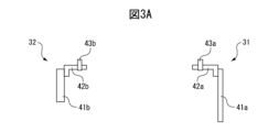
- FIG. 3A is a diagram showing the first and second fixed parts
- FIG. 3B is an exploded view of the first and second fixed parts shown in FIG. 3A.
- the first fixed part 31 includes a plate part 41a to be fixed to the fixed member 21, a bracket 42a extending perpendicular to the plate part 41a, and a first grip part 43a attached to the bracket 42a.
- the second fixed part 32 includes a plate part 41b to be fixed to the movable member 22, a bracket 42b extending perpendicular to the plate part 41b, and a second grip part 43b attached to the bracket 42b.
- the fixed member 21 and the plate portion 41a, and the movable member 22 and the plate portion 41b may be fixed with a fastener, such as a bolt. Any fastener that can be attached and removed may be used.
- the plate portion 41a and the bracket 42a, and the plate portion 41b and the bracket 42b may be fixed with a fastener, such as a bolt, or with an adhesive.
- the first gripping portion 43a and the second gripping portion 43b serve to partially grip the filament L.
- the first gripping portion 43a and the second gripping portion 43b may be, for example, a pressing clamp member or a resin band.
- the first gripping portion 43a and the second gripping portion 43b may also be structured to grip the filament L while wrapped in a protective member such as a rubber sheet.
- the plate portion 41a of the first fixed portion 31 is disposed outside the fixed member 21, and the plate portion 41b of the second fixed portion 32 is disposed outside the movable member 22.
- the bracket 42a attached to the plate portion 41a enters the inside of the hollow hole 29 from one end of the actuator 5, while the bracket 42b attached to the plate portion 41b enters the inside of the hollow hole 29 from the other end of the actuator 5. Therefore, the length A1 between the first gripping portion 43a and the second gripping portion 43b on a line parallel to the central axis of the actuator 5 is shorter than the net length A2 in the axial direction of the hollow hole 29.
- the length A1 between the first gripping portion 43a and the second gripping portion 43b refers to the length measured when the phase of the first gripping portion 43a and the phase of the second gripping portion 43b around the rotation axis are aligned and when the first gripping portion 43a and the second gripping portion 43b are fixed relatively immovably with respect to the hollow hole 29.
- FIG. 4 is a partial perspective view of the pipe member.
- a notch 23b extending in the circumferential direction is formed at one end of the extension 23a.
- FIG. 4 also shows an area C including the notch 23b. The case where the notch 23b is formed in the extension 23a in this way is also included in the scope of this disclosure.
- the length from one end of the extension 23a to the first gripping portion 43a is preferably less than half the axial length A2 of the extension 23a.
- the length from the other end of the extension 23a to the second gripping portion 43b is preferably less than half the axial length A2 of the extension 23a.
- the length from one end of the extension 23a to the first gripping portion 43a and the length from the other end of the extension 23a to the second gripping portion 43b be equal to or less than one-fourth of the axial length A2. This is to prevent the weight of the brackets 42a, 42b equipped with the gripping portions 43a, 43b from increasing. In addition, as described below, this is also to facilitate the fixing operation of the first fixing portion 31 and the second fixing portion 32.
- the filament L has a certain amount of slack between the first gripping portion 43a and the second gripping portion 43b. Specifically, the length of the portion of the filament L that is held by the first gripping portion 43a and the second gripping portion 43b and is between the first gripping portion 43a and the second gripping portion 43b is longer than the net axial length A2 of the hollow hole 29.
- both the first gripping portion 43a of the first fixing portion 31 and the second gripping portion 43b of the second fixing portion 32 are located inside the hollow hole 29.
- only the plate portions 41a, 41b of the first fixing portion 31 and the second fixing portion 32 are exposed to the outside of the actuator 5.
- the plate portions 41a, 41b are, for example, sheet metal having a predetermined thickness, their exposed portions are extremely small.
- the first gripping portion 43a and the second gripping portion 43b are located inside the hollow hole 29, and the exposed portion by the plate portions 41a and 41b is extremely small. This prevents the actuator 5 from becoming large. Furthermore, it also prevents the robot 1 equipped with the actuators 5a to 5f from becoming large.
- the filament L has a certain amount of slack between the first gripping portion 43a and the second gripping portion 43b. Therefore, even if the fixed member 21 and the movable member 22 rotate relatively when the actuator 5 is incorporated in a joint of the robot 1, the slack absorbs the twist of the filament L. In other words, it is possible to prevent the filament L from being damaged due to excessive stress being applied thereto, and also to prevent the filament L from being kinked.
- the two fixing parts 31, 32 of the filament L are completely exposed to the outside, and then the first gripping parts 43a and the second gripping parts 43b on the first fixing part 31 and the second fixing part 32 are both inserted into the hollow hole of the extension part 23a, the amount of slack in the filament L becomes too large. In such a case, the filament L is pressed strongly against the inner surface of the hollow hole, which may result in a shortened life of the filament L.
- FIG. 9 is an axial cross-sectional view of an actuator in the prior art.
- the first gripping portion 43a of the first fixing portion 31 protrudes outward from one end of the hollow hole 29 by a protrusion amount B1
- the second gripping portion 43b of the second fixing portion 32 protrudes outward from the other end of the hollow hole 29 by a protrusion amount B2.
- the actuator 5' to have a drawback in that it becomes larger in the axial direction by the protrusion amounts B1 and B2.
- the housing (not shown) of a robot equipped with multiple actuators 5' also becomes larger according to the length of the actuators 5'.
- FIGS. 5A and 5B are diagrams showing a method for manufacturing the actuator shown in FIG. 2.
- the first fixing portion 31 and the second fixing portion 32 have already been assembled as shown in FIG. 3A, and both the first fixing portion 31 and the second fixing portion 32 are not yet fixed to the actuator 5.
- the filament L is passed through the hollow hole 29, and a portion of the filament L is "temporarily fixed" to the first gripping portion 43a of the first fixing portion 31.
- the filament L is pulled in the direction of the arrow in FIG. 5A until the filament L is fully extended. This causes the plate portion 41a of the first fixing portion 31 to abut against the rear end surface of the fixing member 21. In this state, the other portion of the filament L is properly gripped by the second gripping portion 43b of the second fixing portion 32.
- the gripping of the filament L by the second gripping portion 43b is performed outside the actuator 5.
- the filament L is pulled in the opposite direction to fully extend it.
- the plate portion 41b of the second fixed portion 32 comes into contact with the front end surface of the movable member 22, and the plate portion 41a of the first fixed portion 31 moves away from the fixed member 21.
- the plate portion 41b of the second fixed portion 32 is fixed to the end surface of the movable member 22 as described above.
- the first gripping portion 43a of the first fixed portion 31 is caused to formally grip the aforementioned portion of the filament L.
- the gripping operation of the filament L by the first gripping portion 43a is performed outside the actuator 5.
- the plate portion 41a of the first fixed portion 31 is fixed to the end face of the fixed member 21.
- the filament L has a predetermined slack between the first gripping portion 43a and the second gripping portion 43b, and the length of the slack is longer than the axial length A2 of the hollow hole 29.
- the fixing operations of fixing the plate portions 41a, 41b to the fixed member 21 and the movable member 22, respectively, and the gripping operation of the filament L by the first gripping portion 43a and the second gripping portion 43b are performed outside the actuator 5. It will be understood that the fixing operation of the first fixed portion 31 and the second fixed portion 32 can therefore be performed smoothly and easily.
- the manufacturing procedure is not limited to the above.
- the fixing work may start from either of the two fixing portions 31 and 32.
- FIG. 6A is another diagram showing the first and second fixing parts
- FIG. 6B is an exploded view of the first and second fixing parts shown in FIG. 6A.
- the first fixing part 31 shown in these drawings has at least one ring-shaped spacer N (four ring-shaped spacers N in FIG. 6A) between the plate part 41a and the bracket 42a.
- the plate part 41a, the at least one ring-shaped spacer N, and the bracket 42a are connected to each other by a bolt 50.
- the plate part 41a, the at least one ring-shaped spacer N, and the bracket 42a may be connected by another method, such as an adhesive, without using the bolt 50.
- the second fixing portion 32 includes a single spacer W1 having a predetermined dimension between the plate portion 41b and the bracket 42b.
- the plate portion 41b, the spacer W1, and the bracket 42b may be joined by adhesive, or may be joined by bolts (not shown).
- the presence of at least one ring-shaped spacer N and spacer W1 moves the gripping position of the filament L gripped by the first gripping portion 43a and the second gripping portion 43b to the axial center position of the hollow hole 29. In other words, the two gripping positions of the filament L shift farther away from one end of the hollow hole 29 toward the other end. As a result, the presence of at least one ring-shaped spacer N and spacer W1 increases the amount of slack in the filament L.
- the spacer W1 is replaced with another spacer W2, which is larger than the spacer W1, and the spacer W2 is placed between the plate portion 41b and the bracket 42b. This shifts the second gripping portion 43b of the second fixing portion 32 further away from the end of the hollow hole 29, and as a result, the amount of slack in the filament L is further increased.
- FIG. 6B shows that two of the four ring-shaped spacers N are removed, and the remaining two ring-shaped spacers N are placed between the plate portion 41a and the bracket 42a.
- the amount of slack in the filament L can be changed.
- at least one ring-shaped spacer N, bolt 50, and spacers W1, W2 serve as an adjustment mechanism for adjusting the amount of slack in the filament L.
- the amount of slack in the filament L inside the hollow hole 29 can be easily adjusted even after the first fixing portion 31 and the second fixing portion 32 are fixed to the actuator 5.
- an annular member such as a washer instead of the ring-shaped spacer N is within the scope of this disclosure.
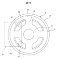
- FIG. 7A is an end view of an actuator in a modified example
- FIG. 7B is a perspective view of the actuator shown in FIG. 7A
- the sensor S includes two sensor components S1 and S2 arranged concentrically.
- the sensor S includes a plurality of strain detection units S3 that connect the sensor components S1 and S2 and extend in the radial direction of the actuator 5-1.
- the sensor S has a plurality of openings 52 formed therein and surrounded by the sensor components S1 and S2 and the strain detection unit S3.
- the sensor S detects a force acting around the axis of the actuator 5-1 through the elastic deformation of the strain detection unit S3.
- the movable member 22 of the actuator 5 shown in FIG. 2 etc. includes a sensor S. Therefore, the plate portion 41b of the second fixing portion 32 can be directly attached to the end face of the sensor S. However, if at least a portion of the second fixing portion 32 is in partial contact with the sensor S or if the filament L is fixed directly onto the sensor S, this may adversely affect the sensitivity of the sensor S, causing the sensor S to output an undesirable detection result.
- multiple rod-shaped members 44 extend from the plate portion 41b of the second fixed portion 32.
- the multiple rod-shaped members 44 are fixed to the end face of the output portion 23 through the opening 52 of the sensor S. Therefore, in the modified example, the second fixed portion 32 is fixed to the movable member 22 of the actuator 5-1 without contacting the sensor S. In such a case, due to the presence of the second fixed portion 32, the sensor S is not directly subjected to the torsional reaction force from the filament L, and therefore it can be seen that good force control can be performed using the sensor S.
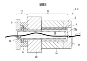
- FIG. 8A is an axial cross-sectional view of an actuator based on a second embodiment
- FIG. 8B is an axial cross-sectional view of an actuator based on a third embodiment.
- the actuator 5-2 shown in FIG. 8A does not have a sensor S.
- the movable member 22 of the actuator 5-2 includes only the output portion 23.
- the second fixed portion 32 is fixed to the end face of the extension portion 23a, that is, the end of the hollow hole 29.
- the fixed member 21 includes the reducer 20 and the motor 10.
- the actuator 5-3 shown in FIG. 8B is equipped with an encoder E on the rear end side of the motor 10.
- the encoder E detects the number of rotations of the motor shaft 13 and the number of rotations of the extension portion 23a, etc., using a known method.
- the fixed member 21 includes the reducer 20, the motor 10, and the encoder E.
- the first fixed portion 31 is attached to the rear end of the encoder E.
- the movable member 22 includes the output portion 23 and the sensor S.
- a driver with a hollow structure may also be mounted on the right side (rearmost end side) of the encoder E.
- the fixed member 21 and movable member 22 of the actuator are not limited to the configuration shown in FIG. 2, and the scope of this disclosure also includes cases where the fixed member 21 includes an encoder E and where the movable member 22 does not include a sensor S.
- An advantage of at least one of the embodiments described above is that, because the first gripping portion and the second gripping portion are located inside the hollow hole 29, the actuator and the robot equipped with such an actuator can be prevented from becoming large.
Landscapes
- Engineering & Computer Science (AREA)
- Robotics (AREA)
- Mechanical Engineering (AREA)
- Manipulator (AREA)
- Mutual Connection Of Rods And Tubes (AREA)
Priority Applications (6)
| Application Number | Priority Date | Filing Date | Title |
|---|---|---|---|
| JP2025506326A JPWO2024189788A1 (https=) | 2023-03-14 | 2023-03-14 | |
| CN202380085141.5A CN120344362A (zh) | 2023-03-14 | 2023-03-14 | 致动器及机器人 |
| PCT/JP2023/009914 WO2024189788A1 (ja) | 2023-03-14 | 2023-03-14 | アクチュエータおよびロボット |
| DE112023005532.7T DE112023005532T5 (de) | 2023-03-14 | 2023-03-14 | Aktuator und roboter |
| TW113105203A TW202436045A (zh) | 2023-03-14 | 2024-02-15 | 致動器及機器人 |
| US19/194,139 US20250256413A1 (en) | 2023-03-14 | 2025-04-30 | Actuator and robot |
Applications Claiming Priority (1)
| Application Number | Priority Date | Filing Date | Title |
|---|---|---|---|
| PCT/JP2023/009914 WO2024189788A1 (ja) | 2023-03-14 | 2023-03-14 | アクチュエータおよびロボット |
Related Child Applications (1)
| Application Number | Title | Priority Date | Filing Date |
|---|---|---|---|
| US19/194,139 Continuation US20250256413A1 (en) | 2023-03-14 | 2025-04-30 | Actuator and robot |
Publications (1)
| Publication Number | Publication Date |
|---|---|
| WO2024189788A1 true WO2024189788A1 (ja) | 2024-09-19 |
Family
ID=92754725
Family Applications (1)
| Application Number | Title | Priority Date | Filing Date |
|---|---|---|---|
| PCT/JP2023/009914 Ceased WO2024189788A1 (ja) | 2023-03-14 | 2023-03-14 | アクチュエータおよびロボット |
Country Status (6)
| Country | Link |
|---|---|
| US (1) | US20250256413A1 (https=) |
| JP (1) | JPWO2024189788A1 (https=) |
| CN (1) | CN120344362A (https=) |
| DE (1) | DE112023005532T5 (https=) |
| TW (1) | TW202436045A (https=) |
| WO (1) | WO2024189788A1 (https=) |
Citations (2)
| Publication number | Priority date | Publication date | Assignee | Title |
|---|---|---|---|---|
| WO2022138370A1 (ja) * | 2020-12-22 | 2022-06-30 | ファナック株式会社 | 線条体一体型アクチュエータ、ユニットおよびロボット |
| WO2023026434A1 (ja) * | 2021-08-26 | 2023-03-02 | ファナック株式会社 | 線条体固定構造、機械、ロボット、及びアクチュエータ |
Family Cites Families (5)
| Publication number | Priority date | Publication date | Assignee | Title |
|---|---|---|---|---|
| US5240092A (en) * | 1992-03-19 | 1993-08-31 | W. L. Gore & Associates, Inc. | Moving strain relief for spiralled flexible cable |
| JP6506195B2 (ja) | 2016-03-09 | 2019-04-24 | ファナック株式会社 | 回転軸モジュールおよび多関節ロボット |
| JP6827437B2 (ja) * | 2018-03-30 | 2021-02-10 | ファナック株式会社 | ロボット用駆動ユニット、ロボットおよびシール構造 |
| JP7319105B2 (ja) * | 2019-06-27 | 2023-08-01 | ファナック株式会社 | 回転軸構造およびロボット |
| TWI810960B (zh) * | 2022-06-02 | 2023-08-01 | 直得科技股份有限公司 | 機器手臂關節、連接件及機器手臂 |
-
2023
- 2023-03-14 JP JP2025506326A patent/JPWO2024189788A1/ja active Pending
- 2023-03-14 CN CN202380085141.5A patent/CN120344362A/zh active Pending
- 2023-03-14 DE DE112023005532.7T patent/DE112023005532T5/de active Pending
- 2023-03-14 WO PCT/JP2023/009914 patent/WO2024189788A1/ja not_active Ceased
-
2024
- 2024-02-15 TW TW113105203A patent/TW202436045A/zh unknown
-
2025
- 2025-04-30 US US19/194,139 patent/US20250256413A1/en active Pending
Patent Citations (2)
| Publication number | Priority date | Publication date | Assignee | Title |
|---|---|---|---|---|
| WO2022138370A1 (ja) * | 2020-12-22 | 2022-06-30 | ファナック株式会社 | 線条体一体型アクチュエータ、ユニットおよびロボット |
| WO2023026434A1 (ja) * | 2021-08-26 | 2023-03-02 | ファナック株式会社 | 線条体固定構造、機械、ロボット、及びアクチュエータ |
Also Published As
| Publication number | Publication date |
|---|---|
| US20250256413A1 (en) | 2025-08-14 |
| DE112023005532T5 (de) | 2026-02-26 |
| CN120344362A (zh) | 2025-07-18 |
| TW202436045A (zh) | 2024-09-16 |
| JPWO2024189788A1 (https=) | 2024-09-19 |
Similar Documents
| Publication | Publication Date | Title |
|---|---|---|
| JP7401517B2 (ja) | ねじりシリーズ弾性アクチュエータ | |
| US11331815B2 (en) | Rotary shaft structure and robot | |
| CN103517790B (zh) | 多关节型工业用机械手 | |
| US20190009417A1 (en) | Driving mechanism, robot arm, and robot system | |
| JP5833836B2 (ja) | 多関節型産業用ロボット | |
| JP5699617B2 (ja) | 電動シリンダ及び電動シリンダシステム | |
| EP1666218B1 (en) | Guiding device for an umbilical member of a robot and a robot having the guiding device | |
| WO2014185373A1 (ja) | リンク作動装置 | |
| US6455799B1 (en) | Robot device | |
| JP7623505B2 (ja) | 線条体固定構造、機械、ロボット、及びアクチュエータ | |
| WO2024189788A1 (ja) | アクチュエータおよびロボット | |
| JP2005518512A (ja) | 車両駆動シャフト及び芯合せ組み立て方法 | |
| JPH11303966A (ja) | 電動シリンダ装置およびその製造方法 | |
| US20200096021A1 (en) | Resistance welding apparatus | |
| WO2023079707A1 (ja) | 回転軸構造、及び機械 | |
| TWI713815B (zh) | 工具承座的工具旋緊方法及工具承座 | |
| WO2024201937A1 (ja) | アクチュエータ | |
| WO2024189919A1 (ja) | アクチュエータ | |
| WO2025052653A1 (ja) | アクチュエータおよびロボット | |
| JPH0938887A (ja) | コンプライアンス機構 | |
| WO2023026435A1 (ja) | 回転軸構造、及び機械 | |
| EP4265937A1 (en) | Method of manufacturing speed reducer, speed reducer, and rotating device | |
| CN117300945A (zh) | 一种工件夹持装置 | |
| WO2024241360A1 (ja) | アクチュエータおよびロボット | |
| KR20260020040A (ko) | 토크 센서 |
Legal Events
| Date | Code | Title | Description |
|---|---|---|---|
| 121 | Ep: the epo has been informed by wipo that ep was designated in this application |
Ref document number: 23927409 Country of ref document: EP Kind code of ref document: A1 |
|
| WWE | Wipo information: entry into national phase |
Ref document number: 2025506326 Country of ref document: JP |
|
| WWE | Wipo information: entry into national phase |
Ref document number: 202380085141.5 Country of ref document: CN |
|
| WWP | Wipo information: published in national office |
Ref document number: 202380085141.5 Country of ref document: CN |
|
| WWE | Wipo information: entry into national phase |
Ref document number: 112023005532 Country of ref document: DE |
|
| WWP | Wipo information: published in national office |
Ref document number: 112023005532 Country of ref document: DE |
|
| 122 | Ep: pct application non-entry in european phase |
Ref document number: 23927409 Country of ref document: EP Kind code of ref document: A1 |