WO2024185352A1 - 通信装置および通信方法 - Google Patents
通信装置および通信方法 Download PDFInfo
- Publication number
- WO2024185352A1 WO2024185352A1 PCT/JP2024/003241 JP2024003241W WO2024185352A1 WO 2024185352 A1 WO2024185352 A1 WO 2024185352A1 JP 2024003241 W JP2024003241 W JP 2024003241W WO 2024185352 A1 WO2024185352 A1 WO 2024185352A1
- Authority
- WO
- WIPO (PCT)
- Prior art keywords
- communication
- communication terminal
- terminal
- evaluation value
- quality information
- Prior art date
- Legal status (The legal status is an assumption and is not a legal conclusion. Google has not performed a legal analysis and makes no representation as to the accuracy of the status listed.)
- Ceased
Links
Images







Classifications
-
- H—ELECTRICITY
- H04—ELECTRIC COMMUNICATION TECHNIQUE
- H04B—TRANSMISSION
- H04B7/00—Radio transmission systems, i.e. using radiation field
- H04B7/14—Relay systems
- H04B7/15—Active relay systems
-
- H—ELECTRICITY
- H04—ELECTRIC COMMUNICATION TECHNIQUE
- H04B—TRANSMISSION
- H04B17/00—Monitoring; Testing
- H04B17/30—Monitoring; Testing of propagation channels
- H04B17/309—Measuring or estimating channel quality parameters
- H04B17/318—Received signal strength
-
- H—ELECTRICITY
- H04—ELECTRIC COMMUNICATION TECHNIQUE
- H04M—TELEPHONIC COMMUNICATION
- H04M1/00—Substation equipment, e.g. for use by subscribers
- H04M1/72—Mobile telephones; Cordless telephones, i.e. devices for establishing wireless links to base stations without route selection
- H04M1/724—User interfaces specially adapted for cordless or mobile telephones
- H04M1/72403—User interfaces specially adapted for cordless or mobile telephones with means for local support of applications that increase the functionality
- H04M1/72409—User interfaces specially adapted for cordless or mobile telephones with means for local support of applications that increase the functionality by interfacing with external accessories
- H04M1/72412—User interfaces specially adapted for cordless or mobile telephones with means for local support of applications that increase the functionality by interfacing with external accessories using two-way short-range wireless interfaces
-
- H—ELECTRICITY
- H04—ELECTRIC COMMUNICATION TECHNIQUE
- H04M—TELEPHONIC COMMUNICATION
- H04M3/00—Automatic or semi-automatic exchanges
- H04M3/42—Systems providing special services or facilities to subscribers
- H04M3/56—Arrangements for connecting several subscribers to a common circuit, i.e. affording conference facilities
-
- H—ELECTRICITY
- H04—ELECTRIC COMMUNICATION TECHNIQUE
- H04W—WIRELESS COMMUNICATION NETWORKS
- H04W4/00—Services specially adapted for wireless communication networks; Facilities therefor
- H04W4/06—Selective distribution of broadcast services, e.g. multimedia broadcast multicast service [MBMS]; Services to user groups; One-way selective calling services
- H04W4/10—Push-to-Talk [PTT] or Push-On-Call services
-
- H—ELECTRICITY
- H04—ELECTRIC COMMUNICATION TECHNIQUE
- H04W—WIRELESS COMMUNICATION NETWORKS
- H04W76/00—Connection management
- H04W76/10—Connection setup
- H04W76/14—Direct-mode setup
-
- H—ELECTRICITY
- H04—ELECTRIC COMMUNICATION TECHNIQUE
- H04W—WIRELESS COMMUNICATION NETWORKS
- H04W88/00—Devices specially adapted for wireless communication networks, e.g. terminals, base stations or access point devices
- H04W88/02—Terminal devices
- H04W88/06—Terminal devices adapted for operation in multiple networks or having at least two operational modes, e.g. multi-mode terminals
-
- H—ELECTRICITY
- H04—ELECTRIC COMMUNICATION TECHNIQUE
- H04W—WIRELESS COMMUNICATION NETWORKS
- H04W92/00—Interfaces specially adapted for wireless communication networks
- H04W92/16—Interfaces between hierarchically similar devices
- H04W92/18—Interfaces between hierarchically similar devices between terminal devices
Definitions
- the present invention relates to communication technology, and in particular to a communication device and a communication method that use multiple wireless communication systems.
- the PTT (Push to Talk) function provides users with the ease of use of a half-duplex radio. Users can call and talk to multiple other users by simply pressing the talk button without having to enter a phone number or other information. The other users can hear the speech from their mobile phones without having to press the answer button.
- the PTT function in mobile phones is also called the PoC (Push-to-Talk over Cellular) function to distinguish it from the PTT function in commercial radios.
- hybrid terminals that have the functions of both mobile phones and commercial radios are also possible.
- the PoC function in a mobile phone communication network such as LTE and the PTT function in a commercial radio communication network can be used depending on the purpose (for example, Patent Document 1).
- hybrid terminals that combine the functions of commercial radios and PoC terminals are configured on the assumption that they will be connected to a communication method or server that complies with the product's expected specifications, so when trying to operate a system that combines commercial radios and a PoC system, differences in specifications can make it difficult to use the hybrid terminal effectively.
- the present invention was made in consideration of these circumstances, and its purpose is to provide technology that connects to multiple communication terminals operating in multiple wireless communication systems, such as commercial radio systems and PoC systems, and efficiently controls the audio signals received from the multiple communication terminals to provide good playback.
- multiple wireless communication systems such as commercial radio systems and PoC systems
- a communication device that communicates with a first communication terminal that communicates with a first base station device using a first wireless communication method and a second communication terminal that communicates with a second base station device using a second wireless communication method, and includes a communication unit that communicates with the first communication terminal and the second communication terminal, a relay quality acquisition unit that acquires the communication state between the first base station device and the first communication terminal as first relay quality information and acquires the communication state between the second base station device and the second communication terminal as second relay quality information, and a relay quality acquisition unit that acquires the first relay quality information and the second relay quality information.
- the device includes a storage unit that stores an evaluation coefficient relating to the first relay quality information and the second relay quality information; an evaluation value calculation unit that calculates a first evaluation value and a second evaluation value based on the first relay quality information, the second relay quality information, and the evaluation coefficients stored in the storage unit; a selection unit that uses the first evaluation value and the second evaluation value to select one of the first communication terminal and the second communication terminal as a priority terminal; and a control unit that controls to play the audio signal from the priority terminal when the audio signal from the priority terminal changes from a silent state to a voice state within a predetermined period from the time when the audio signal from the non-priority terminal changes from a silent state to a voice state.
- This device is a communication device that communicates with each of a first communication terminal that communicates with a first base station device using a first wireless communication method and a second communication terminal that communicates with a second base station device using a second wireless communication method, and includes a communication unit that communicates with the first communication terminal and the second communication terminal using a third wireless communication method, and acquires first route quality information from the communication state between the first communication terminal and the communication unit and the communication state between the first base station device and the first communication terminal, and acquires second route quality information from the communication state between the second communication terminal and the communication unit and the communication state between the second base station device and the second communication terminal.
- a selection unit that selects one of the first and second communication terminals as a priority terminal using the first and second evaluation values; a storage unit that stores evaluation coefficients related to the first and second route quality information; a storage unit that stores evaluation coefficients related to the first and second route quality information; a selection unit that selects one of the first and second communication terminals as a priority terminal using the first and second evaluation values; and a control unit that controls playback of the audio signal from the priority terminal when the audio signal from the priority terminal changes from a silent state to a voice state within a predetermined period from the time when the audio signal from the non-priority terminal changes from a silent state to a voice state.
- This method is a communication method for communicating with a first communication terminal that communicates with a first base station device by a first wireless communication method and a second communication terminal that communicates with a second base station device by a second wireless communication method, and includes the steps of acquiring a communication state between the first base station device and the first communication terminal as first relay quality information and acquiring a communication state between the second base station device and the second communication terminal as second relay quality information, storing evaluation coefficients related to the first relay quality information and the second relay quality information in a storage unit, calculating a first evaluation value and a second evaluation value based on the first relay quality information and the second relay quality information and the evaluation coefficients stored in the storage unit, selecting one of the first communication terminal and the second communication terminal as a priority terminal using the first evaluation value and the second evaluation value, and controlling to reproduce the voice signal from the priority terminal when the voice signal from the priority terminal changes from a silent state to a voice state within a predetermined period from the time when the voice signal from the non-
- this embodiment it is possible to connect to multiple communication terminals operating in multiple wireless communication systems, such as a commercial radio system and a PoC system, and efficiently control the audio signals received from the multiple communication terminals to provide good playback.
- multiple wireless communication systems such as a commercial radio system and a PoC system
- FIG. 1 is a diagram showing a configuration including a first wireless communication system and a second wireless communication system according to an embodiment.
- FIG. 2 is a diagram illustrating a configuration of the communication device of FIG. 1.
- 3 is a diagram showing a data structure of a database stored in a storage unit in FIG. 2.
- 3 is a diagram showing a data structure of a parameter table stored in a storage unit in FIG. 2 .
- FIG. 3 is a diagram showing the configuration of a control unit in FIG. 2 .
- 6 is a flowchart showing a procedure for determining a priority terminal by the control unit of FIG. 5 .
- 6 is a flowchart showing a procedure for deriving relay quality by the control unit of FIG. 5 .
- FIG. 6 is a flowchart showing a procedure for deriving connection quality by the control unit of FIG. 5 .
- 4 is a diagram showing another data structure of a parameter table stored in the storage unit of FIG. 2 .
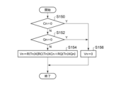
- 6 is a flowchart showing a procedure for deriving an evaluation value by the control unit in FIG. 5 .
- 3 is a flowchart showing a transmission procedure performed by the communication device of FIG. 2;
- FIG. 3 is a diagram illustrating an overview of a receiving process performed by the communication device of FIG. 2.
- 3 is a diagram showing an overview of another receiving process by the communication device of FIG. 2.
- FIG. 3 is a diagram showing another configuration of the control unit in FIG. 2 .
- 15 is a flowchart showing the procedure of the read process of FIG. 14 .
- 15 is a flowchart showing the procedure of the reproducing process of FIG. 14.
- This embodiment relates to a communication device connected to communication terminals corresponding to a plurality of types of wireless communication methods.
- the communication device is a device equipped with a speaker, a microphone, and a PTT button, and capable of making calls via a plurality of connected communication terminals.
- One of the plurality of communication terminals is a smartphone that runs a PoC application.
- Another of the plurality of communication terminals is a commercial radio equipped with a PTT button.
- the commercial radio will also be referred to as a radio.
- the communication device checks the communication connection state between each communication terminal and the communication state between each communication terminal and a base station device, and when the PTT button is pressed, selects the optimal communication terminal to transmit a voice signal, or selectively plays back a voice signal received from a plurality of communication terminals.
- the communication state refers to the quality of communication.
- FIG. 1 shows a configuration including a first wireless communication system 100 and a second wireless communication system 200.
- the first wireless communication system 100 includes a first base station device 110, a first communication terminal 120, a first communication terminal 122, and a first server 130
- the second wireless communication system 200 includes a second base station device 210, a second communication terminal 220, a second communication terminal 222, and a second server 230.
- the number of first base station devices 110 and the number of first servers 130 included in the first wireless communication system 100 are not limited to "1"
- the number of first communication terminals (first communication terminal 120, first communication terminal 122) included in the first wireless communication system 100 are not limited to "2".
- the number of second base station devices 210 and the number of second servers 230 included in the second wireless communication system 200 are not limited to "1", and the number of second communication terminals (second communication terminal 220, second communication terminal 222) included in the second wireless communication system 200 are not limited to "2".
- the first wireless communication system 100 is, for example, a business wireless system, and executes communication between the first base station device 110 and the first communication terminal 120 (first communication terminal 122) by a wireless communication method for business wireless.
- the first server 130 is a server used in the first wireless communication system 100.
- the second wireless communication system 200 is, for example, a PoC system that uses the data communication function of a mobile phone system such as LTE (Long Term Evolution), and executes communication between the second base station device 210 and the second communication terminal 220 (second communication terminal 222) by a wireless communication method for mobile phones.
- the second communication terminal 220 (second communication terminal 222) executes a PoC application.
- the second server 230 is a server used in the second wireless communication system 200.
- the wireless communication method in the first wireless communication system 100 is called the first wireless communication method
- the wireless communication method in the second wireless communication system 200 is called the second wireless communication method.
- the first wireless communication method and the second wireless communication method are different from each other.
- the gateway 10 is connected to the first server 130 and the second server 230, and performs protocol conversion between the first wireless communication system 100 and the second wireless communication system 200. For example, when the gateway 10 receives an audio signal conforming to the protocol of the first wireless communication system 100 from the first server 130, it converts the audio signal into the protocol of the second wireless communication system 200 and transmits the converted audio signal to the second server 230. Also, when the gateway 10 receives an audio signal conforming to the protocol of the second wireless communication system 200 from the second server 230, it converts the audio signal into the protocol of the first wireless communication system 100 and transmits the converted audio signal to the first server 130. Such a gateway 10 transmits audio signals of the same content in the first wireless communication system 100 and the second wireless communication system 200.
- the communication device 300 can communicate with the first communication terminal 120 (first communication terminal 122) and the second communication terminal 220 (second communication terminal 222) by a short-range wireless communication system such as Bluetooth (registered trademark).
- the wireless communication method in the short-range wireless communication system is also called the third wireless communication method.
- the third wireless communication method is different from the first wireless communication method and the second wireless communication method.
- a user uses the communication device 300 to perform voice communication by the first wireless communication system 100 via the first communication terminal 120, and to perform voice communication by the second wireless communication system 200 via the second communication terminal 220.
- FIG. 2 shows the configuration of the communication device 300.
- the communication device 300 includes a communication unit 310, a memory unit 320, a PTT button 330, a microphone 340, a speaker 350, and a control unit 360.
- the communication unit 310 includes a first communication module 312a, a second communication module 312b, and an Nth communication module 312n, which are collectively referred to as communication modules 312.
- Each of the multiple communication modules 312 corresponds to a short-range wireless communication system, and communicates with the first communication terminal 120 (first communication terminal 122), the second communication terminal 220 (second communication terminal 222), and the like in FIG. 1 by the third wireless communication method.
- the first communication module 312a communicates with the first communication terminal 120
- the second communication module 312b communicates with the second communication terminal 220.
- the first communication module 312a is connected to the first communication terminal 120 by pairing with the first communication terminal 120.
- the second communication module 312b is connected to the second communication terminal 220 by pairing with the second communication terminal 220, and communicates with an application of the second communication terminal 220.
- the first communication module 312a periodically attempts to connect and communicate with the first communication terminal 120, and stores the resulting connection and communication state in the memory unit 320.
- the second communication module 312b, and the like, also executes similar processing. The operation of these communication modules 312 is controlled by 360.
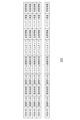
- FIG. 3 shows the data structure of the database stored in the storage unit 320.
- the RSM-ID is identification information for identifying each communication module 312.
- the "connection FLAG” is information indicating whether the communication module 312 is connected to the communication terminal using the third wireless communication method. If connected, the connection FLAG indicates OK, and if not connected, the connection FLAG indicates NG.
- the "radio signal strength” (ICn) indicates the strength when the communication module 312 is connected to the communication terminal using the third wireless communication method, and is shown as, for example, "X dBm".
- Communication FLAG is information indicating whether or not communication with a program running on a communication terminal is possible when the communication module 312 is able to connect to the communication terminal.
- the communication FLAG indicates OK, and when communication is not possible, the communication FLAG indicates NG.
- System connection status is information indicating whether or not a program running on a communication terminal is connected to a communication system used for communication. When connected, the system connection status indicates system connected, and when not connected, the system connection status indicates system not connected.
- System type is information regarding the type of communication system used by the communication terminal. The system type is indicated, for example, as PoC or LMR.
- “Quality information” (IQn) indicates the quality between the communication terminal and the base station device.
- Battery remaining capacity indicates the remaining battery capacity of each communication terminal.
- the battery remaining capacity is indicated, for example, as “Y%” or “Z hours remaining”.
- “Sound quality information” indicates the sound quality level of the communication system.
- the sound quality information is indicated, for example, as “LOW”, “MID”, or “HIGH”.
- the "communication FLAG”, “system connection status”, “system type”, “quality information” (IQn), and “sound quality information” are provided by the communication terminal in response to a request from the communication device 300 to the communication terminal. Return to FIG. 2.
- the PTT button 330 is a button that can be pressed by the user. It is an interface that is operated by the user of the communication device 300. The PTT button 330 outputs the received operation to the control unit 360. When the PTT button 330 is pressed, any one of the communication modules 312 can transmit an audio signal. On the other hand, when the PTT button 330 is not pressed, each communication module 312 can receive an audio signal.
- the microphone 340 captures the voice generated by the user when the user holds down the PTT button 330.
- the microphone 340 converts the captured voice into an electrical signal and outputs the converted voice (hereinafter referred to as "voice signal") to the control unit 360.
- voice signal the converted voice
- the control unit 360 accepts a voice signal from one of the communication modules 312, converts the voice signal into voice, and then outputs the voice.
- This voice signal is a voice signal contained in a signal that one of the communication modules 312 receives from another communication terminal.
- the control unit 360 controls the operation of the communication device 300.
- the first communication module 312a can communicate with the first communication terminal 120
- the second communication module 312b can communicate with the second communication terminal 220.
- either the first communication module 312a or the second communication module 312b transmits a voice signal to the communication terminal
- either the first communication module 312a or the second communication module 312b receives a voice signal from the communication terminal.
- a communication terminal that should be used preferentially for sending and receiving a voice signal is called a "priority terminal”.
- a communication terminal other than the priority terminal is called a "non-priority terminal".
- a priority terminal is a communication terminal that is preferentially used when communicating by comparing the communication state on the first communication terminal 120 side with the communication state on the second communication terminal 220 side.
- the communication state is evaluated by an evaluation value obtained from the connection quality and relay quality described later, and a priority terminal is determined. Based on such evaluation values of the communication state, a priority terminal is determined as needed, while transmitting and receiving voice signals.
- the voice signal is transmitted to a priority terminal determined as needed. This selects a communication terminal with good communication conditions and a high probability of delivering the voice signal more reliably, thereby enabling the voice signal to be delivered more reliably to the communication partner.
- control is performed so that the voice signal arriving from the priority terminal determined as needed is played back preferentially.
- This selects a communication terminal with good communication conditions and a high probability of transmitting more reliably, thereby enabling the voice signal to be played back more reliably and with better quality.
- a process for determining one communication terminal from multiple communication terminals as the priority terminal is described.
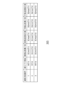
- FIG. 4 shows the data structure of the parameter table stored in the storage unit 320.
- the communication system number (Tn) indicates a number for identifying a wireless communication system or a wireless communication method.
- the first wireless communication method is T1
- the second wireless communication method is T2.
- the weighting coefficient R(Tn) expresses as a coefficient which wireless communication method is to be prioritized for a communication terminal among multiple wireless communication methods. The larger the value of the weighting coefficient R(Tn), the higher the priority.
- Minimum connection quality ICmin(Tn) is the quality of ICn required for use, and indicates that communication is not possible below this value.
- Maximum connection quality ICmax(Tn) is the quality of ICn sufficient for use, and indicates that communication conditions will not change and are good even if the quality is higher than this value.
- Minimum relay quality IQmin(Tn) is the quality of IQn required for use, and indicates that communication is not possible below this value.
- Maximum relay quality IQmax(Tn) is the quality of IQn sufficient for use, and indicates that communication conditions will not change and are good even if the quality is higher than this value.
- FIG. 5 shows the configuration of the control unit 360.
- the control unit 360 includes a relay quality acquisition unit 370, a connection quality acquisition unit 372, a state information acquisition unit 374, an evaluation value calculation unit 376, and a selection unit 378.
- FIG. 6 is a flowchart showing the procedure for determining a priority terminal by the control unit 360.
- the control unit 360 derives relay quality (S10).
- the control unit 360 derives connection quality (S12).
- the control unit 360 derives an evaluation value (S14).
- the control unit 360 determines a priority terminal by comparing the evaluation values (S16).
- the following describes the following in the order of (2-1) derivation of relay quality, (2-2) derivation of connection quality, (2-3) derivation of evaluation value, and (2-4) determination of a priority terminal.
- FIG. 7 is a flowchart showing the procedure for deriving relay quality by the control unit 360.
- the relay quality acquisition unit 370 acquires IQn from the database (S50), and acquires IQmin(Tn) and IQmax(Tn) from the parameter table (S52).
- the relay quality acquisition unit 370 acquires the communication state between the first base station device 110 and the first communication terminal 120 as the first relay quality information Q1, and acquires the communication state between the second base station device 210 and the second communication terminal 220 as the second relay quality information Q2.
- connection quality acquisition unit 372 acquires the quality information ICn from the storage unit 320, and also acquires ICmin(Tn) and ICmax(Tn) from the storage unit 320.
- FIG. 8 is a flowchart showing the procedure for deriving connection quality by the control unit 360.
- the connection quality acquisition unit 372 acquires ICn from the database (S100), and acquires ICmin(Tn) and ICmax(Tn) from the parameter table (S102).
- connection quality acquisition unit 372 acquires the communication state between the first communication terminal 120 and the first communication module 312a as first connection quality information C1, and acquires the communication state between the second communication terminal 220 and the second communication module 312b as second connection quality information C2.
- FIG. 9 is a diagram showing another data structure of the parameter table stored in the storage unit 320.
- the weighting coefficient R(Tn) is stored, but in the parameter table shown in FIG. 9, in addition to this, the connection weighting coefficient RC(Tn) and the relay weighting coefficient RQ(Tn) which indicate the importance of connection and relay, respectively, are also stored.
- the relay weighting coefficient RQ(Tn) is also called the first evaluation coefficient RQ(T1) for the first wireless communication method and the second evaluation coefficient RQ(T2) for the second wireless communication method as a conversion coefficient for making the first relay quality information Q1 and the second relay quality information Q2 comparable as comparable objects.
- the first communication terminal side is a commercial wireless device and the quality information of the relay quality is represented by the radio wave strength in dBm units
- the second communication terminal side is a smartphone and the quality information of the relay quality is represented by the radio wave strength in the number of antenna icons
- the second communication terminal side is a smartphone and the quality information of the relay quality is expressed in units of dBm but with a radio wave strength that has a different range of values than the first communication terminal side
- the relay weighting coefficient RQ(Tn) it becomes possible to evaluate and compare them as being on the same level.
- the relay weighting coefficient RQ(Tn) even if the first communication terminal side is a commercial wireless device and the quality information of the relay quality is expressed in units of dBm but with a radio wave strength that has a different range of values than the first communication terminal side, by introducing the relay weighting coefficient RQ(Tn), it becomes possible to evaluate and compare them as being on the same level.
- connection weighting coefficient RC(Tn) is also called the third evaluation coefficient RC(T1) on the first communication terminal side and the fourth evaluation coefficient RC(T2) on the second communication terminal side as a conversion coefficient for making the first connection quality information C1 on the first communication terminal side and the second connection quality information C2 on the second communication terminal side comparable.
- first communication terminal side is a commercial wireless device and the quality information of the connection quality is represented by radio wave strength in dBm units
- the second communication terminal side is a smartphone and the quality information of the connection quality is represented by the radio wave strength in the number of antenna icons, by introducing the connection weighting coefficient RC(Tn), it becomes possible to evaluate and compare them as being on the same level.
- the connection weighting coefficient RC(Tn) it becomes possible to evaluate and compare them as being on the same level.
- the connection weighting coefficient RC(Tn) is also called the fifth evaluation coefficient R(T1) of the first communication terminal side and the sixth evaluation coefficient R(T2) of the second communication terminal side.
- the first to sixth evaluation coefficients can be said to be evaluation coefficients for treating the difference in quality information between the first communication terminal and the second communication terminal and the difference in importance between the terminals on an equal footing.
- the coefficients on the T2 side, R(T2)/R(T1), RC(T2)/RC(T1), and RQ(T2)/RQ(T1) may be calculated and stored in advance and used to calculate the evaluation value Vn, simplifying the process.
- the evaluation value calculation unit 376 calculates the first evaluation value V1 based on the first connection quality information C1, the first relay quality information Q1, and the first evaluation coefficient, and calculates the second evaluation value V2 based on the second connection quality information C2, the second relay quality information Q2, and the second evaluation coefficient.
- Vn R(Tn) ⁇ Qn ⁇ Cn
- the evaluation is performed using only the relay quality Qn without using the connection quality Cn
- it is preferable to calculate Vn with Cn 1, or to omit the multiplication process of Cn and calculate Vn.
- the weighting coefficient of the reference target is 1, so the multiplication process may be omitted.
- the first wireless communication method is T1 and the second wireless communication method is T2
- a weighting coefficient calculated so as to be normalized with the T1 side as a reference is stored
- R(T1)/R(T1) 1
- the coefficient of the T2 side may be calculated and stored in advance as R(T2)/R(T1), and used to calculate the evaluation value Vn, to simplify the process.
- no weighting is performed in R(Tn)
- the evaluation value calculation unit 376 may calculate the evaluation value Vn as follows.
- Vn Cn + RQ (Tn) x Qn
- V1 C1 + Q1
- RQ (T1) / RQ (T1) 1, for example, when a coefficient calculated so as to be normalized based on the T1 side is stored.
- RQ (T1) 1, for example, when a coefficient calculated so as to be normalized based on the T1 side is stored.
- the multiplication process of RQ (T1) may be omitted to simplify the process.
- At least one calculation result of RQ (T2) / RQ (T1) may be stored as an evaluation coefficient in the parameter table stored in the storage unit 320, and used when calculating the evaluation value Vn.
- the combination of the connection quality Cn and the relay quality Qn may be called the nth route quality information. That is, the nth route quality information includes two types of elements, connection quality Cn and relay quality Qn, as elements of the nth route quality information.
- an evaluation coefficient corresponding to the stored element of the nth route quality information is used to multiply the element of the nth route quality information by the evaluation coefficient corresponding to the element of the nth route quality information, and the elements of the nth route quality information multiplied by the corresponding evaluation coefficients are added together to calculate the evaluation value Vn.
- V1 C1+Q1
- V2 C2+RQ(T2)/RQ(T1) ⁇ Q2
- the coefficient on the T2 side may be calculated and stored in advance as RQ(T2)/RQ(T1), and used to calculate evaluation value Vn, simplifying the process.
- at least one calculation result of RQ(T2)/RQ(T1) may be stored as an evaluation coefficient in the parameter table stored in storage unit 320, and used when calculating evaluation value Vn.
- the selection unit 378 compares a plurality of evaluation values and selects the communication terminal with the larger evaluation value as the priority terminal. Specifically, the selection unit 378 compares the first evaluation value V1 and the second evaluation value V2, and selects the first communication terminal 120 as the priority terminal when the first evaluation value V1 is larger than the second evaluation value V2. On the other hand, the selection unit 378 selects the second communication terminal 220 as the priority terminal when the second evaluation value V2 is larger than the first evaluation value V1.
- first evaluation value V1 and the second evaluation value V2 are the same or the magnitude of the difference between the first evaluation value V1 and the second evaluation value V2 is equal to or smaller than a predetermined value, it may be determined in advance whether to select the first communication terminal 120 or the second communication terminal 220.
- the state information acquisition unit 374 acquires state information of each communication terminal from the database of the storage unit 320.
- the state information acquisition unit 374 acquires state information of the first communication terminal 120 (hereinafter referred to as "first state information") and state information of the second communication terminal 220 (hereinafter referred to as "second state information").
- the state information of the communication terminal includes, for example, remaining battery power and sound quality information.
- the state information may include at least one of power saving mode information, predicted available time, communication type, communication delay time, and communication packet loss rate.
- the selection unit 378 determines that the first evaluation value V1 and the second evaluation value V2 are the same or the magnitude of the difference between the first evaluation value V1 and the second evaluation value V2 is equal to or less than a predetermined value and one of the first communication terminal 120 and the second communication terminal 220 cannot be selected, the selection unit 378 selects one of the first communication terminal 120 and the second communication terminal 220 based on the first status information and the second status information. The selection unit 378 selects the communication terminal with the greater remaining battery power or the communication terminal with the higher sound quality level.
- the control unit 360 checks whether there is a communication terminal connected to the communication module 312 and capable of communicating with the base station device. If only one communication terminal is present, the control unit 360 decides to use the communication module 312 connected to that communication terminal. For example, the control unit 360 decides to use the first communication module 312a when only the first communication terminal 120 is present, and decides to use the second communication module 312b when only the second communication terminal 220 is present.
- the control unit 360 selects the priority terminal that has already been determined. For example, the control unit 360 selects the first communication terminal 120 when the first communication terminal 120 is the priority terminal, and selects the second communication terminal 220 when the second communication terminal 220 is the priority terminal.
- control unit 360 When the control unit 360 selects a communication terminal, it accepts an audio signal from the microphone 340.
- the control unit 360 generates a digital audio signal (hereinafter also referred to as an "audio signal") by converting the audio signal from an analog signal to a digital signal.
- the control unit 360 outputs the audio signal to the communication module 312 connected to the selected communication terminal.
- the communication module 312 transmits the audio signal to the communication terminal.
- the control unit 360 selects a communication terminal that is not a priority terminal. At that time, the control unit 360 outputs an audio signal to the communication module 312 that is connected to the selected communication terminal.
- the control unit 360 may add header information to the audio signal.
- the communication system ID of the wireless communication system that includes the communication terminal selected for transmission is added to the header information.
- FIG. 11 is a flowchart showing the transmission procedure by the communication device 300.
- the PTT button 330 waits for an operation (S200).
- the PTT button 330 is pressed (S202).
- the control unit 360 creates candidates for communication terminals that are connected to the communication module 312 and are capable of communication (S204). If the number of candidates is "0" (Y in S206), the control unit 360 determines that transmission is not possible, outputs an error sound from the speaker 350 (S208), and returns to step 200.
- control unit 360 selects a communication terminal with a higher priority (S212), transmits a voice signal using the selected communication terminal (S214), and returns to step 200. If the number of candidates is "1" (Y in S210), the control unit 360 selects one candidate as the communication terminal (S216), transmits a voice signal using the selected communication terminal (S214), and returns to step 200.
- Each of the multiple communication modules 312 in the communication device 300 receives an audio signal from a communication terminal.
- the control unit 360 does not play all of the audio signals received by each communication module 312, but selects and plays one of the multiple audio signals.
- the horizontal axis indicates time.
- the upper row shows communication with a priority terminal
- the lower row shows communication with a communication terminal that is not a priority terminal (hereinafter referred to as a "non-priority terminal").
- a non-priority terminal hereinafter referred to as a "non-priority terminal”.
- an audio signal from a priority terminal is received before an audio signal from a non-priority terminal.
- the communication unit 310 of the communication device 300 is not receiving an audio signal from the priority terminal and an audio signal from a non-priority terminal, the communication unit 310 starts receiving an audio signal from the priority terminal and does not start receiving an audio signal from the non-priority terminal.
- the control unit 360 controls to play the audio signal from the priority terminal.
- the played audio is output from the speaker 350. Even if the communication unit 310 starts receiving an audio signal from a non-priority terminal while playing the audio signal from the priority terminal, the control unit 360 does not play the audio signal from the non-priority terminal.
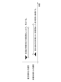
- FIG. 13 shows an overview of another reception process by communication device 300.
- the horizontal axis indicates time.
- the upper row shows communication with a non-priority terminal, and the lower row shows communication with a priority terminal.
- the communication unit 310 of communication device 300 is not receiving an audio signal from either the priority terminal or the non-priority terminal, it starts receiving an audio signal from the non-priority terminal, but does not start receiving an audio signal from the priority terminal.
- the control unit 360 pre-sets a predetermined period (hereinafter also referred to as "standby time") T for waiting to receive an audio signal from the priority terminal. If the audio signal from the priority terminal does not change from a silent state to a voice state within the standby time T after the audio signal from the non-communicating terminal changes from a silent state to a voice state, the control unit 360 controls to play the audio signal from the non-priority terminal. In other words, the audio signal from the non-priority terminal is played with a delay of the standby time T.
- the control unit 360 controls to play the audio signal from the priority terminal. Therefore, the audio signal from the non-priority terminal is not played.
- FIG. 14 shows another configuration of the control unit 360.
- the control unit 360 includes a first read process 400a and a second read process 400b, collectively referred to as the read process 400, a first state FLAG 402a and a second state FLAG 402b, collectively referred to as the state FLAG 402, a first audio signal 404a and a second audio signal 404b, collectively referred to as the audio signal 404, and a playback process 406.
- FIG. 15 is a flowchart showing the procedure of the read process 400. This process is executed for each node.
- the read process 400 sets the status FLAG 402 to "waiting to receive” (S250).
- the read process 400 acquires the status of the communication module 312 (S252). If there is no audio signal 404 (N in S254), the process returns to step 252. If there is an audio signal 404 (Y in S254), the read process 400 sets the status FLAG 402 to "receiving" (S256).
- the read process 400 receives the audio signal 404 (S258) and stores the audio signal 404 in a buffer memory (S260).
- the buffer memory is realized, for example, by a FIFO (First In, First Out) memory.
- the buffer memory may also be included in the storage unit 320.
- the read process 400 acquires the status of the communication module 312 (S262). If there is an audio signal 404 (Y in S264), the process returns to step 258. If there is no audio signal 404 (N in S264), the read process 400 sets the status flag 402 to "waiting to receive" (S266) and returns to step 252.
- the status flag 402 is set and the process is changed depending on whether there is an audio signal 404 or not, but a command may be used to obtain whether the communication terminal is receiving, and the status flag 402 may be set and the operation may be changed based on that information.
- FIG. 16 is a flowchart showing the procedure of the regeneration process 406.
- the regeneration process 406 acquires the status of all nodes (S300). If all status FLAGs 402 are "waiting to receive” (Y in S302), the process returns to step 300. If all status FLAGs 402 are not "waiting to receive” (N in S302), the regeneration process 406 sets the reception start time to the current time (S304). The regeneration process 406 acquires the status of all nodes (S306).
- the regeneration process 406 sets the priority node as the node to be regenerated (hereafter referred to as the "regeneration target node") (S310).
- the regeneration process 406 sets t to the current time - the reception start time (S312). If t > T is not true (N in S314), the process returns to step 306. If t > T (Y in S314), the node that has been in the state of T time since the reception start time is set as the regeneration target node (S316).
- the playback process 406 reads the audio signal 404 from the buffer memory of the node to be played back (S318) and plays back the read audio signal 404 (S320). If there is an audio signal 404 remaining in the buffer memory of the node to be played back (Y in S322), the process returns to step 318. If there is no audio signal 404 remaining in the buffer memory of the node to be played back (N in S322), the playback process 406 acquires the status of all nodes (S324). If all status FLAGs 402 are not "waiting to receive” (N in S326), the process returns to step 324. If all status FLAGs 402 are "waiting to receive” (Y in S326), the process returns to step 300.
- this configuration can be realized by the CPU, memory, and other LSIs of any computer, and in terms of software, it can be realized by programs loaded into memory, but here we are illustrating functional blocks that are realized by the cooperation of these. Therefore, those skilled in the art will understand that these functional blocks can be realized in various ways using only hardware, only software, or a combination of both.
- the first evaluation value is calculated from the first connection quality information, the first relay quality information, and the first evaluation coefficient for the first communication terminal using the first wireless communication method
- the second evaluation value is calculated from the second connection quality information, the second relay quality information, and the second evaluation coefficient for the second communication terminal using the second wireless communication method, so that the first evaluation value and the second evaluation value can be compared. Furthermore, since the first evaluation value and the second evaluation value are compared, one of the first communication terminal and the second communication terminal can be selected as a priority terminal. Furthermore, since one of the first communication terminal and the second communication terminal is selected as the priority terminal, the priority terminal can be used even if multiple communication terminals are available.
- the priority terminal is used even if multiple communication terminals are available, multiple communication terminals operated in multiple wireless communication systems can be used as a whole. Furthermore, since the priority terminal is used for transmission, multiple communication terminals operated in multiple wireless communication systems can be used as a whole.
- the voice signal from the priority terminal is in a voice state
- the voice signal from the priority terminal is controlled to be played, so that multiple communication terminals operated in multiple wireless communication systems can be used as one.
- the voice signal from the priority terminal changes from a silent state to a voice state within a specified period after the voice signal from the non-priority terminal changes from a silent state to a voice state
- the voice signal from the priority terminal is controlled to be played, so that multiple communication terminals operated in multiple wireless communication systems can be used as one.
- the voice signal from the priority terminal does not change from a silent state to a voice state within a specified period after the voice signal from the non-priority terminal changes from a silent state to a voice state
- the voice signal from the non-priority terminal is controlled to be played, so that multiple communication terminals operated in multiple wireless communication systems can be used as one.
- connection quality information and relay quality information used by the evaluation value calculation unit 376 in this embodiment are configured such that the connection quality information is acquired by the connection quality acquisition unit 372, and the relay quality information is acquired by the relay quality acquisition unit 370.
- a route quality acquisition unit having the functions of the connection quality acquisition unit 372 and the relay quality acquisition unit 370 may be provided, and the route quality information may be acquired by the route quality acquisition unit.
- the elements of this route quality information may include the connection quality information and the relay quality information.
- the evaluation value calculation unit 376 in this embodiment calculates the evaluation value based on the connection quality information and the relay quality information.
- the evaluation value calculation unit 376 may calculate the evaluation value based on the relay quality information.
- the evaluation value is calculated by multiplying the relay quality information by a relay weighting coefficient. This corresponds to a case where the evaluation value is calculated by including only the relay quality information as an element of the route quality information. According to this modified example, the calculation of the evaluation value can be simplified.
- the present invention can connect to multiple communication terminals operating in multiple wireless communication systems, including commercial radio systems and PoC systems, and efficiently control the audio signals received from the multiple communication terminals to provide good playback.
- 10 Gateway 100 First wireless communication system, 110 First base station device, 120, 122 First communication terminal, 130 First server, 200 Second wireless communication system, 210 Second base station device, 220, 222 Second communication terminal, 230 Second server, 300 Communication device, 310 Communication unit, 312 Communication module, 320 Memory unit, 330 PTT button, 340 Microphone, 350 Speaker, 360 Control unit, 370 Relay quality acquisition unit, 372 Connection quality acquisition unit, 374 Status information acquisition unit, 376 Evaluation value calculation unit, 378 Selection unit, 400 Read process, 402 Status FLAG, 404 Audio signal, 406 Playback process.
Landscapes
- Engineering & Computer Science (AREA)
- Computer Networks & Wireless Communication (AREA)
- Signal Processing (AREA)
- Quality & Reliability (AREA)
- Physics & Mathematics (AREA)
- Electromagnetism (AREA)
- Multimedia (AREA)
- Human Computer Interaction (AREA)
- Mobile Radio Communication Systems (AREA)
- Telephonic Communication Services (AREA)
Abstract
中継品質取得部(370)は、第1基地局装置と第1通信端末との間の通信状態を第1中継品質情報として取得するとともに、第2基地局装置と第2通信端末との間の通信状態を第2中継品質情報として取得する。評価値算出部(376)は、第1中継品質情報および第2中継品質情報と記憶部に記憶された評価係数とに基づいて第1評価値および第2評価値を算出する。選択部(378)は、第1評価値と第2評価値を用いて、第1通信端末と第2通信端末のうちの1つを優先端末として選択する。
Description
本発明は、通信技術に関し、特に複数の無線通信システムを使用する通信装置および通信方法に関する。
PTT(Push to Talk)機能は、半二重無線機のような使い勝手をユーザに提供する機能である。ユーザは電話番号などを入力することなく通話ボタンを押すだけで、他の複数のユーザに発呼し、発話することができる。他のユーザは、応答ボタンを押さなくてもそのユーザの携帯電話機から発話内容が音声出力される。携帯電話機におけるPTT機能は、業務用無線機のPTT機能と区別してPoC(Push-to-Talk over Cellular)機能とも呼ばれる。一方、携帯電話機と業務用無線機の両方の機能を備えたハイブリッド端末が考えられる。ハイブリッド機では、LTE等の携帯電話機の通信ネットワークにおけるPoC機能と、業務用無線機の通信ネットワークにおけるPTT機能の双方が目的によって使い分けられる(例えば、特許文献1)。
従来、業務用無線機とPoC端末の機能を備えるハイブリッド端末では、製品が想定する仕様に準じた通信方式や通信対象となるサーバに接続されることを前提としてハイブリッド端末が構成されるため、持ち寄った業務用無線機のシステムとPoCのシステムとを活用して運用しようとした場合、仕様の違いからハイブリッド端末をうまく活用できないことがある。
本発明はこうした状況に鑑みてなされたものであり、その目的は、業務用無線機のシステムやPoCのシステムからなる複数の無線通信システムで運用されている複数の通信端末と接続し、複数の通信端末から受信される音声信号を効率良く制御して良好な再生となる技術を提供することである。
上記課題を解決するために、本実施形態のある態様の通信装置は、第1基地局装置との間で第1無線通信方式により通信する第1通信端末および第2基地局装置との間で第2無線通信方式により通信する第2通信端末のそれぞれと通信する通信装置であって、第1通信端末および第2通信端末と通信する通信部と、第1基地局装置と第1通信端末との間の通信状態を第1中継品質情報として取得するとともに、第2基地局装置と第2通信端末との間の通信状態を第2中継品質情報として取得する中継品質取得部と、第1中継品質情報と第2中継品質情報とに関する評価係数を記憶する記憶部と、第1中継品質情報および第2中継品質情報と記憶部に記憶された評価係数とに基づいて第1評価値および第2評価値を算出する評価値算出部と、第1評価値と第2評価値を用いて、第1通信端末と第2通信端末のうちの1つを優先端末として選択する選択部と、非優先端末からの音声信号が無音状態から有音声状態となった時点から所定期間内に優先端末からの音声信号が無音状態から有音声状態となった場合、優先端末からの音声信号を再生するよう制御する制御部と を備える。
本実施形態の別の態様もまた、通信装置である。この装置は、第1基地局装置との間で第1無線通信方式により通信する第1通信端末および第2基地局装置との間で第2無線通信方式により通信する第2通信端末のそれぞれと通信する通信装置であって、第1通信端末および第2通信端末と第3無線通信方式により通信する通信部と、第1通信端末と通信部との間の通信状態と、第1基地局装置と第1通信端末との間の通信状態とから、第1経路品質情報を取得するとともに、第2通信端末と通信部との間の通信状態と、第2基地局装置と第2通信端末との間の通信状態とから、第2経路品質情報を取得する経路情報取得部と、第1経路品質情報と第2経路品質情報とに関する評価係数を記憶する記憶部と、第1経路品質情報および第2経路品質情報と、記憶部に記憶された評価係数とに基づいて、第1評価値と第2評価値とを算出する評価値算出部と、第1評価値と第2評価値を用いて、第1通信端末と第2通信端末のうちの1つを優先端末として選択する選択部と、非優先端末からの音声信号が無音状態から有音声状態となった時点から所定期間内に優先端末からの音声信号が無音状態から有音声状態となった場合、優先端末からの音声信号を再生するよう制御する制御部とを備える。
本実施形態のさらに別の態様は、通信方法である。この方法は、第1基地局装置との間で第1無線通信方式により通信する第1通信端末および第2基地局装置との間で第2無線通信方式により通信する第2通信端末のそれぞれと通信する通信方法であって、第1基地局装置と第1通信端末との間の通信状態を第1中継品質情報として取得するとともに、第2基地局装置と第2通信端末との間の通信状態を第2中継品質情報として取得するステップと、第1中継品質情報と第2中継品質情報とに関する評価係数が記憶部に記憶されており、第1中継品質情報および第2中継品質情報と記憶部に記憶された評価係数とに基づいて第1評価値および第2評価値を算出するステップと、第1評価値と第2評価値を用いて、第1通信端末と第2通信端末のうちの1つを優先端末として選択するステップと、非優先端末からの音声信号が無音状態から有音声状態となった時点から所定期間内に優先端末からの音声信号が無音状態から有音声状態となった場合、優先端末からの音声信号を再生するよう制御するステップとを含む。
なお、以上の構成要素の任意の組合せ、本実施形態の表現を方法、装置、システム、記録媒体、コンピュータプログラムなどの間で変換したものもまた、本実施形態の態様として有効である。
本実施形態によれば、業務用無線機のシステムやPoCのシステムからなる複数の無線通信システムで運用されている複数の通信端末と接続し、複数の通信端末から受信される音声信号を効率良く制御して良好な再生とすることができる。
本実施例を具体的に説明する前に、まず概要を述べる。本実施例は、複数種類の無線通信方式のそれぞれに対応した通信端末に接続される通信装置に関する。通信装置は、スピーカ、マイク、PTTボタンを備え、接続された複数の通信端末を介して通話可能な装置である。複数の通信端末のうちの1つは、PoCアプリケーションを動作させるスマートフォンである。また、複数の通信端末のうちの別の1つは、PTTボタンを備えた業務用無線機である。以下、業務用無線機を無線機とも呼ぶ。通信装置は、各通信端末との間の通信接続状態と各通信端末と基地局装置との間の通信状態を確認しながら、PTTボタンが押された際に最適な通信端末を選択して音声信号を送信したり、複数の通信端末から受信する音声信号を選択的に再生したりする。ここで、通信状態は通信の品質のことである。以下では、(1)システムの概要、(2)優先端末の決定処理、(3)送信処理、(4)受信処理の順に説明する。
(1)システムの概要
図1は、第1無線通信システム100と第2無線通信システム200を含む構成を示す。第1無線通信システム100は、第1基地局装置110、第1通信端末120、第1通信端末122、第1サーバ130を含み、第2無線通信システム200は、第2基地局装置210、第2通信端末220、第2通信端末222、第2サーバ230を含む。第1無線通信システム100に含まれる第1基地局装置110の数、第1サーバ130の数は「1」に限定されず、第1無線通信システム100に含まれる第1通信端末(第1通信端末120、第1通信端末122)の数は「2」に限定されない。第2無線通信システム200に含まれる第2基地局装置210の数、第2サーバ230の数は「1」に限定されず、第2無線通信システム200に含まれる第2通信端末(第2通信端末220、第2通信端末222)の数は「2」に限定されない。
図1は、第1無線通信システム100と第2無線通信システム200を含む構成を示す。第1無線通信システム100は、第1基地局装置110、第1通信端末120、第1通信端末122、第1サーバ130を含み、第2無線通信システム200は、第2基地局装置210、第2通信端末220、第2通信端末222、第2サーバ230を含む。第1無線通信システム100に含まれる第1基地局装置110の数、第1サーバ130の数は「1」に限定されず、第1無線通信システム100に含まれる第1通信端末(第1通信端末120、第1通信端末122)の数は「2」に限定されない。第2無線通信システム200に含まれる第2基地局装置210の数、第2サーバ230の数は「1」に限定されず、第2無線通信システム200に含まれる第2通信端末(第2通信端末220、第2通信端末222)の数は「2」に限定されない。
第1無線通信システム100は、例えば、業務用無線システムであり、業務用無線の無線通信方式により、第1基地局装置110と第1通信端末120(第1通信端末122)との間の通信を実行する。第1サーバ130は、第1無線通信システム100において使用されるサーバである。第2無線通信システム200は、例えば、LTE(Long Term Evolution)等の携帯電話システムのデータ通信機能を使用するPoCシステムであり、携帯電話の無線通信方式により、第2基地局装置210と第2通信端末220(第2通信端末222)との間の通信を実行する。第2通信端末220(第2通信端末222)はPoCアプリケーションを実行する。第2サーバ230は、第2無線通信システム200において使用されるサーバである。第1無線通信システム100における無線通信方式を第1無線通信方式と呼ぶ場合、第2無線通信システム200における無線通信方式は第2無線通信方式と呼ばれる。第1無線通信方式と第2無線通信方式は互いに異なる。
ゲートウエイ10は、第1サーバ130と第2サーバ230とに接続され、第1無線通信システム100と第2無線通信システム200との間でプロトコル変換を実行する。例えば、ゲートウエイ10は、第1無線通信システム100のプロトコルにしたがった音声信号を第1サーバ130から受信すると、第2無線通信システム200のプロトコルに当該音声信号を変換し、変換した音声信号を第2サーバ230に送信する。また、ゲートウエイ10は、第2無線通信システム200のプロトコルにしたがった音声信号を第2サーバ230から受信すると、第1無線通信システム100のプロトコルに当該音声信号を変換し、変換した音声信号を第1サーバ130に送信する。このようなゲートウエイ10によって、第1無線通信システム100と第2無線通信システム200とにおいて同一内容の音声信号が伝送される。
通信装置300は、例えば、Bluetooth(登録商標)等の近距離無線通信システムにより、第1通信端末120(第1通信端末122)、第2通信端末220(第2通信端末222)と通信可能である。近距離無線通信システムにおける無線通信方式は第3無線通信方式とも呼ばれる。第3無線通信方式は、第1無線通信方式および第2無線通信方式とは異なる。ユーザは、通信装置300を使用して、第1通信端末120を介して第1無線通信システム100により音声通信を実行したり、第2通信端末220を介して第2無線通信システム200により音声通信を実行したりする。
図2は、通信装置300の構成を示す。通信装置300は、通信部310、記憶部320、PTTボタン330、マイク340、スピーカ350、制御部360を含む。通信部310は、通信モジュール312と総称される第1通信モジュール312a、第2通信モジュール312b、第N通信モジュール312nを含む。
複数の通信モジュール312のそれぞれは、近距離無線通信システムに対応し、第3無線通信方式により、図1の第1通信端末120(第1通信端末122)、第2通信端末220(第2通信端末222)等と通信を実行する。例えば、第1通信モジュール312aは第1通信端末120と通信し、第2通信モジュール312bは第2通信端末220と通信する。第1通信モジュール312aは、第1通信端末120とペアリングすることによって、第1通信端末120に接続される。また、第2通信モジュール312bは、第2通信端末220とペアリングすることによって第2通信端末220に接続され、第2通信端末220のアプリケーションと通信する。第1通信モジュール312aは、第1通信端末120との接続と通信を定期的に試み、その結果の接続通信状態を記憶部320に記憶する。第2通信モジュール312b等も同様の処理を実行する。これらの通信モジュール312の動作は360により制御される。
図3は、記憶部320に記憶されるデータベースのデータ構造を示す。RSM-IDは、各通信モジュール312を識別するための識別情報である。「接続FLAG」は、通信モジュール312が通信端末と第3無線通信方式により接続されたか否かを示す情報である。接続された場合に接続FLAGはOKを示し、接続されなかった場合に接続FLAGはNGを示す。「電波強度」(ICn)は、通信モジュール312が通信端末と第3無線通信方式により接続された場合の強度を示し、例えば、「XdBm」のように示される。
「通信FLAG」は、通信モジュール312が通信端末に接続できた場合に、通信端末で動作するプログラムと通信できるか否かを示す情報である。通信できた場合に通信FLAGはOKを示し、通信できなかった場合に通信FLAGはNGを示す。「システム接続状態」は、通信端末で動作するプログラムが通信に使用する通信システムに接続されている否かを示す情報である。接続されている場合にシステム接続状態はシステム接続中を示し、接続されていない場合にシステム接続状態はシステム未接続を示す。「システムタイプ」は、通信端末が利用する通信システムのタイプに関する情報である。システムタイプは、例えば、PoC、LMRのように示される。「品質情報」(IQn)は、通信端末と基地局装置との間の品質を示す。「バッテリ残量」は各通信端末のバッテリの残量を示す。バッテリ残量は、例えば「Y%」、「残りZ時間」のように示される。「音質情報」は、通信システムの音質レベルを示す。音質情報は、例えば、「LOW」、「MID」、「HIGH」のように示される。「通信FLAG」、「システム接続状態」、「システムタイプ」、「品質情報」(IQn)、「音質情報」は、通信装置300から通信端末に提供を要求することによって、通信端末から提供される。図2に戻る。
PTTボタン330はユーザが押下げ可能な釦である。通信装置300を使用するユーザによって操作されるインターフェースである。PTTボタン330は、受けつけた操作を制御部360に出力する。PTTボタン330が押し下げられている場合に、いずれかの通信モジュール312は音声信号を送信可能である。一方、PTTボタン330が押し下げられていない場合に、各通信モジュール312は音声信号を受信可能である。
マイク340は、ユーザがPTTボタン330を押し下げている場合に、ユーザにより発生された音声を取得する。マイク340は、取得した音声を電気信号に変換し、変換した音声(以下、「音声信号」という)を制御部360に出力する。制御部360は、ユーザがPTTボタンを押し下げていない場合に、いずれかの通信モジュール312から音声信号を受けつけ、音声信号を音声に変換してから音声を出力する。この音声信号は、いずれかの通信モジュール312が他の通信端末から受信した信号に含まれた音声信号である。制御部360は通信装置300の動作を制御する。
(2)優先端末の決定処理
以下では、説明を明瞭にするために、第1通信モジュール312aが第1通信端末120と通信可能であり、第2通信モジュール312bが第2通信端末220と通信可能である状況を想定する。具体的に説明すると、第1通信モジュール312aと第2通信モジュール312bのいずれかは、通信端末に音声信号を送信したり、第1通信モジュール312aと第2通信モジュール312bのいずれかは通信端末からの音声信号を受信したりする。複数の通信端末のうち、音声信号の送受信のために優先的に使用すべき通信端末は「優先端末」と呼ばれる。また、複数の通信端末のうち、優先端末以外の通信端末は「非優先端末」と呼ばれる。優先端末は、第1通信端末120側の通信状態と第2通信端末220側の通信状態とを比較し、通信する際に優先的に使用する通信状態がより良い通信端末である。通信状態は、後述する接続品質や中継品質から求められる評価値により評価し、優先端末を決定する。このような通信状態の評価値により、随時、優先端末を決定しつつ、音声信号の送信や受信を行う。音声信号を送信する場合は、随時決定される優先端末に対して音声信号の送信を行う。これにより、通信状態が良くより確実に音声信号を届けられる可能性が高い通信端末が選択され、より確実に音声信号を通信相手に届けられるようにしている。音声信号を受信する場合は、随時決定される優先端末から到来する音声信号を優先的に再生するよう制御する。これにより、通信状態が良くより確実に送信された可能性の高い通信端末が選択され、より確実で品質の良い音声信号を再生できるようにしている。ここでは、複数の通信端末から1つの通信端末を優先端末として決定するための処理を説明する。
以下では、説明を明瞭にするために、第1通信モジュール312aが第1通信端末120と通信可能であり、第2通信モジュール312bが第2通信端末220と通信可能である状況を想定する。具体的に説明すると、第1通信モジュール312aと第2通信モジュール312bのいずれかは、通信端末に音声信号を送信したり、第1通信モジュール312aと第2通信モジュール312bのいずれかは通信端末からの音声信号を受信したりする。複数の通信端末のうち、音声信号の送受信のために優先的に使用すべき通信端末は「優先端末」と呼ばれる。また、複数の通信端末のうち、優先端末以外の通信端末は「非優先端末」と呼ばれる。優先端末は、第1通信端末120側の通信状態と第2通信端末220側の通信状態とを比較し、通信する際に優先的に使用する通信状態がより良い通信端末である。通信状態は、後述する接続品質や中継品質から求められる評価値により評価し、優先端末を決定する。このような通信状態の評価値により、随時、優先端末を決定しつつ、音声信号の送信や受信を行う。音声信号を送信する場合は、随時決定される優先端末に対して音声信号の送信を行う。これにより、通信状態が良くより確実に音声信号を届けられる可能性が高い通信端末が選択され、より確実に音声信号を通信相手に届けられるようにしている。音声信号を受信する場合は、随時決定される優先端末から到来する音声信号を優先的に再生するよう制御する。これにより、通信状態が良くより確実に送信された可能性の高い通信端末が選択され、より確実で品質の良い音声信号を再生できるようにしている。ここでは、複数の通信端末から1つの通信端末を優先端末として決定するための処理を説明する。
図4は、記憶部320に記憶されるパラメータテーブルのデータ構造を示す。通信系統番号(Tn)は、無線通信システムまたは無線通信方式を識別するための番号を示す。例えば、第1無線通信方式がT1であり、第2無線通信方式がT2である。重みづけ係数R(Tn)は、複数の無線通信方式において、どの無線通信方式の通信端末を優先するかを係数として表現する。重みづけ係数R(Tn)の値が大きいほど優先される。
「接続品質最小値」ICmin(Tn)は、使用に必要なICnの品質であり、これ以下では通信不可能であることを示す。「接続品質最大値」ICmax(Tn)は、使用に十分なICnの品質であり、これ以上あっても通信状況は変わらず良好であることを示す。「中継品質最小値」IQmin(Tn)は、使用に必要なIQnの品質であり、これ以下では通信不可能であることを示す。「中継品質最大値」IQmax(Tn)は、使用に十分なIQnの品質であり、これ以上あっても通信状況は変わらず良好であることを示す。これらの値は利用環境やユーザのポリシーによって予め定められる。
図5は、制御部360の構成を示す。制御部360は、中継品質取得部370、接続品質取得部372、状態情報取得部374、評価値算出部376、選択部378を含む。図6は、制御部360による優先端末の決定手順を示すフローチャートである。制御部360は、中継品質を導出する(S10)。制御部360は、接続品質を導出する(S12)。制御部360は、評価値を導出する(S14)。制御部360は、各評価値の比較により優先端末を決定する(S16)。以下では、(2-1)中継品質の導出、(2-2)接続品質の導出、(2-3)評価値の導出、(2-4)優先端末の決定の順に説明する。
(2-1)中継品質の導出
中継品質取得部370は、品質情報IQnを記憶部320から取得するとともに、IQmin(Tn)、IQmax(Tn)も記憶部320から取得する。中継品質取得部370は、これらをもとに中継品質Qnを次のように計算する。
Qn=(IQn-IQmin(Tn))/(IQmax(Tn)-IQmin(Tn))
ここで、Qn≦0であればQn=0であり、1≦Qnであれば、Qn=1である。
中継品質取得部370は、品質情報IQnを記憶部320から取得するとともに、IQmin(Tn)、IQmax(Tn)も記憶部320から取得する。中継品質取得部370は、これらをもとに中継品質Qnを次のように計算する。
Qn=(IQn-IQmin(Tn))/(IQmax(Tn)-IQmin(Tn))
ここで、Qn≦0であればQn=0であり、1≦Qnであれば、Qn=1である。
このような中継品質取得部370の処理は次のように示される。図7は、制御部360による中継品質の導出手順を示すフローチャートである。中継品質取得部370は、データベースよりIQnを取得し(S50)、パラメータテーブルよりIQmin(Tn)、IQmax(Tn)を取得する(S52)。中継品質取得部370は、Qn=(IQn-IQmin(Tn))/(IQmax(Tn)-IQmin(Tn))を計算する(S54)。中継品質取得部370は、Qn≦0であれば(S56のY)、Qn=0とする(S58)。中継品質取得部370は、Qn≦0でなければ(S56のN)、ステップ58をスキップする。中継品質取得部370は、1≦Qnであれば(S60のY)、Qn=1とする(S62)。中継品質取得部370は、1≦Qnでなければ(S60のN)、ステップ62をスキップする。図5に戻る。
例えば、品質情報が電波強度である場合、IQmin(Tn)=95dBm、IQmax(Tn)=125dBmとする。これより、Qn=(IQn-95)/(125-95)と示される。IQnが95dBm以下であれば、Qnが0以下となるので、Qnは0とされる。また、IQnが125dBm以上であれば、Qnが1以上となるので、Qnは1とされる。
例えば、第2通信端末220において電波強度をアンテナアイコンの本数0~4本で表示している場合、これらをIQ=1~4とする。また、IQmin=1(アンテナアイコン1本以下は通信できないと判断)、IQmax=3(アンテナアイコン3本以上であれば状況にかかわらず良好に通信できる)とする。これより、Qn=(IQ-1)/(3-1)と示される。アンテナアイコン1本以下であれば、Qnが0以下となるので、Qnは0とされる。また、アンテナアイコン3本以上であれば、Qnが1以上となるので、Qnは1とされる。このように中継品質取得部370は、第1基地局装置110と第1通信端末120との間の通信状態を第1中継品質情報Q1として取得するとともに、第2基地局装置210と第2通信端末220との間の通信状態を第2中継品質情報Q2として取得する。
(2-2)接続品質の導出
接続品質取得部372は、品質情報ICnを記憶部320から取得するとともに、ICmin(Tn)、ICmax(Tn)も記憶部320から取得する。接続品質取得部372は、これらをもとに接続品質Cnを次のように計算する。
Cn=(ICn-ICmin(Tn))/(ICmax(Tn)-ICmin(Tn))
ここで、Cn≦0であればCn=0であり、1≦CnであればCn=1である。
接続品質取得部372は、品質情報ICnを記憶部320から取得するとともに、ICmin(Tn)、ICmax(Tn)も記憶部320から取得する。接続品質取得部372は、これらをもとに接続品質Cnを次のように計算する。
Cn=(ICn-ICmin(Tn))/(ICmax(Tn)-ICmin(Tn))
ここで、Cn≦0であればCn=0であり、1≦CnであればCn=1である。
このような接続品質取得部372の処理は次のように示される。図8は、制御部360による接続品質の導出手順を示すフローチャートである。接続品質取得部372は、データベースよりICnを取得し(S100)、パラメータテーブルよりICmin(Tn)、ICmax(Tn)を取得する(S102)。接続品質取得部372は、Cn=(ICn-ICmin(Tn))/(ICmax(Tn)-ICmin(Tn))を計算する(S104)。接続品質取得部372は、Cn≦0であれば(S106のY)、Cn=0とする(S108)。接続品質取得部372は、Cn≦0でなければ(S106のN)、ステップ108をスキップする。接続品質取得部372は、1≦Cnであれば(S110のY)、Cn=1とする(S112)。接続品質取得部372は、1≦Cnでなければ(S110のN)、ステップ112をスキップする。図5に戻る。
このように接続品質取得部372は、第1通信端末120と第1通信モジュール312aとの間の通信状態を第1接続品質情報C1として取得するとともに、第2通信端末220と第2通信モジュール312bとの間の通信状態を第2接続品質情報C2として取得する。
(2-3)評価値の導出
図9は、記憶部320に記憶されるパラメータテーブルの別のデータ構造を示す図である。図4に示したパラメータテーブルでは重みづけ係数R(Tn)が記憶されているが、図9に示したパラメータテーブルでは、これに加えて、接続、中継それぞれの重要度を表す接続重みづけ係数RC(Tn)、中継重みづけ係数RQ(Tn)も記憶される。特に、中継重みづけ係数RQ(Tn)は、第1中継品質情報Q1と第2中継品質情報Q2とを同等の比較対象として比較可能にするための変換係数として、第1無線通信方式に対する第1評価係数RQ(T1)と、第2無線通信方式に対する第2評価係数RQ(T2)とも呼ばれる。ここで、例えば、第1通信端末側が業務用無線機で中継品質の品質情報がdBmを単位とする電波強度、第2通信端末側がスマートフォンで中継品質の品質情報が電波強度をアンテナアイコンの本数で表されている場合であっても、中継重みづけ係数RQ(Tn)を導入することにより、同列のものとして評価し、比較することができるようになる。別の構成として、例えば、第1通信端末側が業務用無線機で中継品質の品質情報がdBmを単位とする電波強度、第2通信端末側がスマートフォンで中継品質の品質情報がdBmを単位とするが第1通信端末側とは数値の取り得る範囲が異なる電波強度で表されている場合であっても、中継重みづけ係数RQ(Tn)を導入することにより、同列のものとして評価し、比較することができるようになる。更に別の構成として、例えば、第1通信端末側が業務用無線機で中継品質の品質情報が電波強度をアンテナアイコンの本数、第2通信端末側がスマートフォンで中継品質の品質情報が電波強度を第1通信端末側とは異なるアンテナアイコンの本数で表されている場合であっても、中継重みづけ係数RQ(Tn)を導入することにより、同列のものとして評価し、比較することができるようになる。また、接続重みづけ係数RC(Tn)は、第1通信端末側の第1接続品質情報C1と第2通信端末側の第2接続品質情報C2とを比較可能にするための変換係数として、第1通信端末側の第3評価係数RC(T1)と、第2通信端末側の第4評価係数RC(T2)とも呼ばれる。ここで、例えば、第1通信端末側が業務用無線機で接続品質の品質情報がdBmを単位とする電波強度、第2通信端末側がスマートフォンで接続品質の品質情報が電波強度をアンテナアイコンの本数で表されている場合であっても、接続重みづけ係数RC(Tn)を導入することにより、同列のものとして評価し、比較することができるようになる。また、別の構成として、例えば、第1通信端末側が業務用無線機で接続品質の品質情報がdBmを単位とする電波強度、第2通信端末側がスマートフォンで接続品質の品質情報がdBmを単位とするが第1通信端末側とは数値レンジが異なる電波強度で表されている場合であっても、接続重みづけ係数RC(Tn)を導入することにより、同列のものとして評価し、比較することができるようになる。更に別の構成として、例えば、第1通信端末側が業務用無線機で接続品質の品質情報が電波強度をアンテナアイコンの本数、第2通信端末側がスマートフォンで接続品質の品質情報が電波強度を第1通信端末側とは異なるアンテナアイコンの本数で表されている場合であっても、接続重みづけ係数RC(Tn)を導入することにより、同列のものとして評価し、比較することができるようになる。更に、重みづけ係数R(Tn)は、第1通信端末側の第5評価係数R(T1)と、第2通信端末側の第6評価係数R(T2)とも呼ばれる。この第1評価係数から第6評価係数は、第1通信端末と第2通信端末との品質情報の違いや端末間の重要度の違いを同列に扱うための評価係数であるともいえる。図5に戻る。
図9は、記憶部320に記憶されるパラメータテーブルの別のデータ構造を示す図である。図4に示したパラメータテーブルでは重みづけ係数R(Tn)が記憶されているが、図9に示したパラメータテーブルでは、これに加えて、接続、中継それぞれの重要度を表す接続重みづけ係数RC(Tn)、中継重みづけ係数RQ(Tn)も記憶される。特に、中継重みづけ係数RQ(Tn)は、第1中継品質情報Q1と第2中継品質情報Q2とを同等の比較対象として比較可能にするための変換係数として、第1無線通信方式に対する第1評価係数RQ(T1)と、第2無線通信方式に対する第2評価係数RQ(T2)とも呼ばれる。ここで、例えば、第1通信端末側が業務用無線機で中継品質の品質情報がdBmを単位とする電波強度、第2通信端末側がスマートフォンで中継品質の品質情報が電波強度をアンテナアイコンの本数で表されている場合であっても、中継重みづけ係数RQ(Tn)を導入することにより、同列のものとして評価し、比較することができるようになる。別の構成として、例えば、第1通信端末側が業務用無線機で中継品質の品質情報がdBmを単位とする電波強度、第2通信端末側がスマートフォンで中継品質の品質情報がdBmを単位とするが第1通信端末側とは数値の取り得る範囲が異なる電波強度で表されている場合であっても、中継重みづけ係数RQ(Tn)を導入することにより、同列のものとして評価し、比較することができるようになる。更に別の構成として、例えば、第1通信端末側が業務用無線機で中継品質の品質情報が電波強度をアンテナアイコンの本数、第2通信端末側がスマートフォンで中継品質の品質情報が電波強度を第1通信端末側とは異なるアンテナアイコンの本数で表されている場合であっても、中継重みづけ係数RQ(Tn)を導入することにより、同列のものとして評価し、比較することができるようになる。また、接続重みづけ係数RC(Tn)は、第1通信端末側の第1接続品質情報C1と第2通信端末側の第2接続品質情報C2とを比較可能にするための変換係数として、第1通信端末側の第3評価係数RC(T1)と、第2通信端末側の第4評価係数RC(T2)とも呼ばれる。ここで、例えば、第1通信端末側が業務用無線機で接続品質の品質情報がdBmを単位とする電波強度、第2通信端末側がスマートフォンで接続品質の品質情報が電波強度をアンテナアイコンの本数で表されている場合であっても、接続重みづけ係数RC(Tn)を導入することにより、同列のものとして評価し、比較することができるようになる。また、別の構成として、例えば、第1通信端末側が業務用無線機で接続品質の品質情報がdBmを単位とする電波強度、第2通信端末側がスマートフォンで接続品質の品質情報がdBmを単位とするが第1通信端末側とは数値レンジが異なる電波強度で表されている場合であっても、接続重みづけ係数RC(Tn)を導入することにより、同列のものとして評価し、比較することができるようになる。更に別の構成として、例えば、第1通信端末側が業務用無線機で接続品質の品質情報が電波強度をアンテナアイコンの本数、第2通信端末側がスマートフォンで接続品質の品質情報が電波強度を第1通信端末側とは異なるアンテナアイコンの本数で表されている場合であっても、接続重みづけ係数RC(Tn)を導入することにより、同列のものとして評価し、比較することができるようになる。更に、重みづけ係数R(Tn)は、第1通信端末側の第5評価係数R(T1)と、第2通信端末側の第6評価係数R(T2)とも呼ばれる。この第1評価係数から第6評価係数は、第1通信端末と第2通信端末との品質情報の違いや端末間の重要度の違いを同列に扱うための評価係数であるともいえる。図5に戻る。
評価値算出部376は、評価値Vnを次のように計算する。
Vn=R(Tn)×{RC(Tn)×Cn+RQ(Tn)×Qn}
ここで、QnとCnのいずれかが0である場合、通信できないのでVn=0とされる。更に、接続品質Cnを利用せずに、中継品質Qnのみ利用して評価を行う場合には、RC(Tn)=0としてVnを算出するか、Cnの乗算処理を省略してVnを算出するとよい。更に、R(Tn)、RC(Tn)およびRQ(Tn)において、比較対象の片方を基準として正規化されるように重みづけ係数として算出されたものが記憶されている場合は、基準となる対象の重みづけ係数は1となるため乗算処理を省略してもよい。例えば、第1無線通信方式がT1、第2無線通信方式がT2であり、T1側を基準として正規化されるように重みづけ係数が算出されたものが記憶されている場合は、R(T1)/R(T1)=1、RC(T1)/RC(T1)=1、RQ(T1)/RQ(T1)=1となることから、V1=C1+Q1とすることで、乗算処理を省略して処理を簡単にしてもよい。また、T2側の係数は、R(T2)/R(T1)、RC(T2)/RC(T1)、RQ(T2)/RQ(T1)をあらかじめ算出して記憶しておき、評価値Vnの計算に利用することで処理を簡単にしてもよい。更に、R(Tn)において、重みづけを行わない場合、つまりR(Tn)=1の場合には、Vn=RC(Tn)×Cn+RQ(Tn)×QnとしてR(Tn)の乗算処理を省略して処理を簡単にしてもよい。
Vn=R(Tn)×{RC(Tn)×Cn+RQ(Tn)×Qn}
ここで、QnとCnのいずれかが0である場合、通信できないのでVn=0とされる。更に、接続品質Cnを利用せずに、中継品質Qnのみ利用して評価を行う場合には、RC(Tn)=0としてVnを算出するか、Cnの乗算処理を省略してVnを算出するとよい。更に、R(Tn)、RC(Tn)およびRQ(Tn)において、比較対象の片方を基準として正規化されるように重みづけ係数として算出されたものが記憶されている場合は、基準となる対象の重みづけ係数は1となるため乗算処理を省略してもよい。例えば、第1無線通信方式がT1、第2無線通信方式がT2であり、T1側を基準として正規化されるように重みづけ係数が算出されたものが記憶されている場合は、R(T1)/R(T1)=1、RC(T1)/RC(T1)=1、RQ(T1)/RQ(T1)=1となることから、V1=C1+Q1とすることで、乗算処理を省略して処理を簡単にしてもよい。また、T2側の係数は、R(T2)/R(T1)、RC(T2)/RC(T1)、RQ(T2)/RQ(T1)をあらかじめ算出して記憶しておき、評価値Vnの計算に利用することで処理を簡単にしてもよい。更に、R(Tn)において、重みづけを行わない場合、つまりR(Tn)=1の場合には、Vn=RC(Tn)×Cn+RQ(Tn)×QnとしてR(Tn)の乗算処理を省略して処理を簡単にしてもよい。
このような評価値算出部376の処理は次のように示される。図10は、制御部360による評価値の導出手順を示すフローチャートである。Cn=0でなく(S150のN)、Qn=0でない場合(S152のN)、評価値算出部376は、Vn=R(Tn)×{RC(Tn)×Cn+RQ(Tn)×Qn}を計算する(S154)。Cn=0である場合(S150のY)、またはQn=0である場合(S152のY)、評価値算出部376は、Vn=0とする(S156)。図5に戻る。このように評価値算出部376は、第1接続品質情報C1と第1中継品質情報Q1と第1評価係数とをもとに第1評価値V1を算出するとともに、第2接続品質情報C2と第2中継品質情報Q2と第2評価係数とをもとに第2評価値V2を算出する。
処理を簡単にするために、評価値算出部376は、次のように評価値Vnを計算してもよい。
Vn=R(Tn)×Qn×Cn
ここで、接続品質Cnを利用せずに、中継品質Qnのみ利用して評価を行う場合には、Cn=1としてVnを算出するか、Cnの乗算処理を省略してVnを算出するとよい。また、R(Tn)において、比較対象の片方を基準として正規化されるように重みづけ係数として算出されたものが記憶されている場合は、基準となる対象の重みづけ係数は1となるため乗算処理を省略してもよい。例えば、第1無線通信方式がT1、第2無線通信方式がT2であり、T1側を基準として正規化されるように重みづけ係数が算出されたものが記憶されている場合は、R(T1)/R(T1)=1となることから、V1=Q1×C1とすることで、R(T1)の乗算処理を省略して処理を簡単にしてもよい。また、T2側の係数は、R(T2)/R(T1)をあらかじめ算出して記憶しておき、評価値Vnの計算に利用することで処理を簡単にしてもよい。更に、R(Tn)において、重みづけを行わない場合、つまりR(Tn)=1の場合には、Vn=Qn×CnとしてR(Tn)の乗算処理を省略して処理を簡単にしてもよい。
Vn=R(Tn)×Qn×Cn
ここで、接続品質Cnを利用せずに、中継品質Qnのみ利用して評価を行う場合には、Cn=1としてVnを算出するか、Cnの乗算処理を省略してVnを算出するとよい。また、R(Tn)において、比較対象の片方を基準として正規化されるように重みづけ係数として算出されたものが記憶されている場合は、基準となる対象の重みづけ係数は1となるため乗算処理を省略してもよい。例えば、第1無線通信方式がT1、第2無線通信方式がT2であり、T1側を基準として正規化されるように重みづけ係数が算出されたものが記憶されている場合は、R(T1)/R(T1)=1となることから、V1=Q1×C1とすることで、R(T1)の乗算処理を省略して処理を簡単にしてもよい。また、T2側の係数は、R(T2)/R(T1)をあらかじめ算出して記憶しておき、評価値Vnの計算に利用することで処理を簡単にしてもよい。更に、R(Tn)において、重みづけを行わない場合、つまりR(Tn)=1の場合には、Vn=Qn×CnとしてR(Tn)の乗算処理を省略して処理を簡単にしてもよい。
また、評価値算出部376は、次のように評価値Vnを計算してもよい。本実施例では、通信装置300と第3無線通信方式で通信接続して第1通信端末および第2通信端末から得られる品質情報が同じ表現形式である場合、例えば、品質情報が電波強度で電波強度の単位がdBmで、電波強度の取り得る範囲も同じである場合には、評価式VnであるVn=R(Tn)×{RC(Tn)×Cn+RQ(Tn)×Qn}において、第1通信端末側をT1、第2通信端末側をT2とすると、RC(T1)とRC(T2)は、ともに1であればよい。また本実施例において、R(Tn)による重みづけを行わない場合、つまりR(Tn)=1の場合には、評価式Vnは、Vn=Cn+RQ(Tn)×Qnと変形できる。第1通信端末側をT1、第2通信端末側をT2とすると以下となる。
V1=C1+RQ(T1)×Q1
V2=C2+RQ(T2)×Q2
上記のRQ(T1)とRQ(T2)を、記憶部320に記憶されるパラメータテーブルとして記憶しておき、評価値算出部376は評価値Vnを計算する際に利用するとよい。
V1=C1+RQ(T1)×Q1
V2=C2+RQ(T2)×Q2
上記のRQ(T1)とRQ(T2)を、記憶部320に記憶されるパラメータテーブルとして記憶しておき、評価値算出部376は評価値Vnを計算する際に利用するとよい。
上述のように変形した評価式VnであるVn=Cn+RQ(Tn)×Qnは、例えば、T1側を基準として正規化されるように係数が算出されたものが記憶されている場合は、RQ(T1)/RQ(T1)=1となることから、V1=C1+Q1と変形できる。このように変形することでRQ(T1)の乗算処理を省略して処理を簡単にしてもよい。また、V2=C2+RQ(T2)/RQ(T1)×Q2と変形し、T2側の係数は、RQ(T2)/RQ(T1)をあらかじめ算出して記憶しておき、評価値Vnの計算に利用することで処理を簡単にしてもよい。つまり、記憶部320に記憶されるパラメータテーブルには、少なくとも1つのRQ(T2)/RQ(T1)の計算結果を評価係数として記憶し、評価値Vnを計算する際に利用すればよい。また、接続品質Cnと中継品質Qnとの組み合わせを第nの経路品質情報と呼んでもよい。つまり、第nの経路品質情報は、第nの経路品質情報の要素として接続品質Cnと中継品質Qnとの2種類の要素を含む。評価値Vnを算出する際には、記憶された第nの経路品質情報の要素に対応する評価係数を利用して、第nの経路品質情報の要素と第nの経路品質情報の要素に対応する評価係数とを乗算し、対応する評価係数が乗算された第nの経路品質情報の要素同士を加算することで評価値Vnが算出される。
更に、V1=C1+Q1、
V2=C2+RQ(T2)/RQ(T1)×Q2
において、接続品質Cnを利用せずに、中継品質Qnのみ利用して評価を行う場合には、Cn=0としてVnを算出するとよい。T2側の係数は、RQ(T2)/RQ(T1)をあらかじめ算出して記憶しておき、評価値Vnの計算に利用することで処理を簡単にしてもよい。つまり、記憶部320に記憶されるパラメータテーブルには、少なくとも1つのRQ(T2)/RQ(T1)の計算結果を評価係数として記憶し、評価値Vnを計算する際に利用すればよい。
V2=C2+RQ(T2)/RQ(T1)×Q2
において、接続品質Cnを利用せずに、中継品質Qnのみ利用して評価を行う場合には、Cn=0としてVnを算出するとよい。T2側の係数は、RQ(T2)/RQ(T1)をあらかじめ算出して記憶しておき、評価値Vnの計算に利用することで処理を簡単にしてもよい。つまり、記憶部320に記憶されるパラメータテーブルには、少なくとも1つのRQ(T2)/RQ(T1)の計算結果を評価係数として記憶し、評価値Vnを計算する際に利用すればよい。
(2-4)優先端末の決定
選択部378は、複数の評価値を比較して、評価値の大きい方の通信端末を優先端末として選択する。具体的に説明すると、選択部378は、第1評価値V1と第2評価値V2とを比較し、第1評価値V1が第2評価値V2よりも大きい場合に、第1通信端末120を優先端末として選択する。一方、選択部378は、第2評価値V2が第1評価値V1よりも大きい場合に、第2通信端末220を優先端末として選択する。第1評価値V1と第2評価値V2とが同一、もしくは第1評価値V1と第2評価値V2との差の大きさが所定値以下である場合、第1通信端末120を選択するか、第2通信端末220を選択するかが予め定められてもよい。
選択部378は、複数の評価値を比較して、評価値の大きい方の通信端末を優先端末として選択する。具体的に説明すると、選択部378は、第1評価値V1と第2評価値V2とを比較し、第1評価値V1が第2評価値V2よりも大きい場合に、第1通信端末120を優先端末として選択する。一方、選択部378は、第2評価値V2が第1評価値V1よりも大きい場合に、第2通信端末220を優先端末として選択する。第1評価値V1と第2評価値V2とが同一、もしくは第1評価値V1と第2評価値V2との差の大きさが所定値以下である場合、第1通信端末120を選択するか、第2通信端末220を選択するかが予め定められてもよい。
複数の評価値、例えば第1評価値V1と第2評価値V2が同一、もしくは第1評価値V1と第2評価値V2との差の大きさが所定値以下である場合、次の処理が実行されてもよい。状態情報取得部374は、記憶部320のデータベースから各通信端末の状態情報を取得する。例えば、状態情報取得部374は、第1通信端末120の状態情報(以下、「第1状態情報」という)と第2通信端末220の状態情報(以下、「第2状態情報」という)を取得する。通信端末の状態情報は、例えば、バッテリ残量、音質情報を含む。状態情報には、省電力モード情報、予測使用可能時間、通信種別、通信遅延時間、通信パケットロス率、の中から少なくとも1つが含まれてもよい。
選択部378は、第1評価値V1と第2評価値V2とが同一、もしくは第1評価値V1と第2評価値V2との差の大きさが所定値以下であり、第1通信端末120と第2通信端末220のうちの1つを選択できないと判定された場合、第1状態情報と第2状態情報とをもとに、第1通信端末120と第2通信端末220のうちの1つを選択する。選択部378は、バッテリ残量の多い方の通信端末を選択したり、音質レベルの高い方の通信端末を選択したりする。
(3)送信処理
通信装置300のPTTボタン330がユーザにより押し下げられると、制御部360は、通信モジュール312に接続され、かつ基地局装置と通信可能な通信端末が存在するかを確認する。1つだけの通信端末が存在する場合、制御部360は、当該通信端末に接続された通信モジュール312の使用を決定する。例えば、制御部360は、第1通信端末120だけが存在する場合に第1通信モジュール312aの使用を決定し、第2通信端末220だけが存在する場合に第2通信モジュール312bの使用を決定する。
通信装置300のPTTボタン330がユーザにより押し下げられると、制御部360は、通信モジュール312に接続され、かつ基地局装置と通信可能な通信端末が存在するかを確認する。1つだけの通信端末が存在する場合、制御部360は、当該通信端末に接続された通信モジュール312の使用を決定する。例えば、制御部360は、第1通信端末120だけが存在する場合に第1通信モジュール312aの使用を決定し、第2通信端末220だけが存在する場合に第2通信モジュール312bの使用を決定する。
複数の通信端末、例えば第1通信端末120と第2通信端末220とが存在する場合、制御部360は、既に決定した優先端末を選択する。例えば、制御部360は、第1通信端末120が優先端末である場合に第1通信端末120を選択し、第2通信端末220が優先端末である場合に第2通信端末220を選択する。
制御部360は、通信端末を選択すると、マイク340からの音声信号を受けつける。制御部360は、音声信号をアナログ信号からデジタル信号に変換することによって、デジタル信号の音声信号(以下、これもまた「音声信号」という)を生成する。制御部360は、選択した通信端末と接続される通信モジュール312に音声信号を出力する。通信モジュール312は、音声信号を通信端末に送信する。
ここで、通信モジュール312が優先端末に接続できない場合、または優先端末が基地局装置と通信できない場合、制御部360は、優先端末ではない通信端末を選択する。その際、制御部360は、選択した通信端末に接続される通信モジュール312に音声信号を出力する。以上の説明に加えて、制御部360は、音声信号にヘッダ情報を付加してもよい。ヘッダ情報には、送信用に選択された通信端末を含む無線通信システムの通信システムIDが付加される。
図11は、通信装置300による送信手順を示すフローチャートである。PTTボタン330は操作待ちをする(S200)。PTTボタン330が押し下げられる(S202)。制御部360は、通信モジュール312に接続され、かつ通信可能な通信端末の候補を作成する(S204)。候補数が「0」である場合(S206のY)、制御部360は、送信不可能と判定し、エラー音をスピーカ350から出力させて(S208)、ステップ200に戻る。
候補数が「0」でなく(S206のN)、「1」でない場合(S210のN)、制御部360は、優先度の高い通信端末を選択してから(S212)、選択した通信端末を使って音声信号を送信(S214)して、ステップ200に戻る。候補数が「1」である場合(S210のY)、制御部360は、1つの候補を通信端末に選択してから(S216)、選択した通信端末を使って音声信号を送信(S214)して、ステップ200に戻る。
(4)受信処理
通信装置300における複数の通信モジュール312のそれぞれは、通信端末からの音声信号を受信する。制御部360は、各通信モジュール312において受信された音声信号の全てを再生せず、複数の音声信号のうちのいずれかを選択して再生する。
通信装置300における複数の通信モジュール312のそれぞれは、通信端末からの音声信号を受信する。制御部360は、各通信モジュール312において受信された音声信号の全てを再生せず、複数の音声信号のうちのいずれかを選択して再生する。
図12は、通信装置300による受信処理の概要を示す。横軸が時間を示す。また、上段に優先端末との通信を示し、下段に優先端末ではない通信端末(以下、「非優先端末」という)との通信を示す。ここでは、非優先端末からの音声信号よりも優先端末からの音声信号を先に受信する場合を想定する。通信装置300の通信部310は、優先端末からの音声信号と非優先端末からの音声信号とを受信していない状態において、優先端末からの音声信号の受信を開始し、非優先端末からの音声信号の受信を開始しない。制御部360は、優先端末からの音声信号が有音声状態である場合、優先端末からの音声信号を再生するよう制御する。再生された音声はスピーカ350から出力される。優先端末からの音声信号を再生している間に、通信部310が非優先端末からの音声信号の受信を開始しても、制御部360は、非優先端末からの音声信号を再生しない。
図13は、通信装置300による別の受信処理の概要を示す。横軸が時間を示す。また、上段に非優先端末との通信を示し、下段に優先端末との通信を示す。ここでは、優先端末からの音声信号よりも非優先端末からの音声信号を先に受信する場合を想定する。通信装置300の通信部310は、優先端末からの音声信号と非優先端末からの音声信号とを受信していない状態において、非優先端末からの音声信号の受信を開始し、優先端末からの音声信号の受信を開始しない。
制御部360は、優先端末からの音声信号の受信を待機する所定期間(以下、「待機時間」ともいう)Tを予め設定する。制御部360は、非通信端末からの音声信号が無音状態から有音声状態となってから待機時間T内に優先端末からの音声信号が無音状態から有音声状態とならなかった場合、非優先端末からの音声信号を再生するよう制御する。つまり、非優先端末からの音声信号は待機時間T遅延して再生される。一方、制御部360は、非優先端末からの音声信号が無音状態から有音声状態となってから待機時間T内に優先端末からの音声信号が無音状態から有音声状態となった場合、優先端末からの音声信号を再生するよう制御する。そのため、非優先端末からの音声信号は再生されない。
図14は、制御部360の別の構成を示す。制御部360は、読み出しプロセス400と総称される第1読み出しプロセス400a、第2読み出しプロセス400b、状態FLAG402と総称される第1状態FLAG402a、第2状態FLAG402b、音声信号404と総称される第1音声信号404a、第2音声信号404b、再生プロセス406を含む。
第1読み出しプロセス400aは、第1通信モジュール312aに接続され、第1通信モジュール312aの状態を確認し、確認した状態を第1状態FLAG402aとして設定する。また、第1読み出しプロセス400aは、第1通信モジュール312aから第1音声信号404aを読み出す。第2読み出しプロセス400bは、第2通信モジュール312bに接続され、第2通信モジュール312bの状態を確認し、確認した状態を第2状態FLAG402bとして設定する。また、第2読み出しプロセス400bは、第2通信モジュール312bから第2音声信号404bを読み出す。再生プロセス406は、第1状態FLAG402aと第2状態FLAG402bを確認し、それに応じて第1音声信号404aと第2音声信号404bのいずれかを再生する。通信モジュール312に応じた一覧の処理単位は「ノード」とも呼ばれる。
図15は、読み出しプロセス400の手順を示すフローチャートである。このプロセスはノード毎に実行される。読み出しプロセス400は、状態FLAG402を「受信待ち」にセットする(S250)。読み出しプロセス400は、通信モジュール312の状態を取得する(S252)。音声信号404がなければ(S254のN)、ステップ252に戻る。音声信号404があれば(S254のY)、読み出しプロセス400は、状態FLAG402を「受信中」にセットする(S256)。読み出しプロセス400は、音声信号404を受信し(S258)、音声信号404をバッファメモリに保存する(S260)。バッファメモリは例えばFIFO(First In, First Out)メモリなどで実現される。また、バッファメモリは、記憶部320に含まれてもよい。読み出しプロセス400は、通信モジュール312の状態を取得する(S262)。音声信号404があれば(S264のY)、ステップ258に戻る。音声信号404がなければ(S264のN)、読み出しプロセス400は、状態FLAG402を「受信待ち」にセット(S266)し、ステップ252に戻る。ここでは、音声信号404の有無で状態FLAG402をセットしたり、処理を変更したりしているが、コマンドによって通信端末が受信中か否かを取得し、それをもって状態FLAG402のセットおよび動作の変更がなされてもよい。
図16は、再生プロセス406の手順を示すフローチャートである。再生プロセス406は全ノードの状態を取得する(S300)。全ての状態FLAG402が「受信待ち」であれば(S302のY)、ステップ300に戻る。全ての状態FLAG402が「受信待ち」でない場合(S302のN)、再生プロセス406は受信開始時刻を現在時刻とする(S304)。再生プロセス406は全ノードの状態を取得する(S306)。
優先端末に対応したノード(以下、「優先ノード」という)の状態FLAG402が「受信中」であれば(S308のY)、再生プロセス406は、優先ノードを再生対象のノード(以下、「再生対象ノード」という)とする(S310)。一方、優先ノードの状態FLAG402が「受信中」でなければ(S308のN)、再生プロセス406は、tを現在時刻-受信開始時刻とする(S312)。t>Tでなければ(S314のN)、ステップ306に戻る。t>Tであれば(S314のY)、受信開始時刻からT時間経過したノードを再生対象ノードとする(S316)。
再生プロセス406は、再生対象ノードのバッファメモリから音声信号404を読み出し(S318)、読み出した音声信号404を再生する(S320)。再生対象ノードのバッファメモリに残り音声信号404があれば(S322のY)、ステップ318に戻る。再生対象ノードのバッファメモリに残り音声信号404がない場合(S322のN)、再生プロセス406は全ノードの状態を取得する(S324)。全ての状態FLAG402が「受信待ち」でなければ(S326のN)、ステップ324に戻る。全ての状態FLAG402が「受信待ち」であれば(S326のY)、ステップ300に戻る。
この構成は、ハードウエア的には、任意のコンピュータのCPU、メモリ、その他のLSIで実現でき、ソフトウエア的にはメモリにロードされたプログラムなどによって実現されるが、ここではそれらの連携によって実現される機能ブロックを描いている。したがって、これらの機能ブロックがハードウエアのみ、ソフトウエアのみ、またはそれらの組合せによっていろいろな形で実現できることは、当業者には理解されるところである。
本実施例によれば、第1無線通信方式を使用する第1通信端末に対する第1接続品質情報と第1中継品質情報と第1評価係数から第1評価値を算出し、第2無線通信方式を使用する第2通信端末に対する第2接続品質情報と第2中継品質情報と第2評価係数から第2評価値を算出するので、第1評価値と第2評価値とを比較できる。また、第1評価値と第2評価値とを比較するので、第1通信端末と第2通信端末のうちの1つを優先端末として選択できる。また、第1通信端末と第2通信端末のうちの1つが優先端末として選択されるので、複数の通信端末が使用可能であっても優先端末を使用できる。また、複数の通信端末が使用可能であっても優先端末が使用されるので、複数の無線通信システムで運用されている複数の通信端末を一体的に利用できる。また、優先端末を送信に使用するので、複数の無線通信システムで運用されている複数の通信端末を一体的に利用できる。
また、優先端末からの音声信号が有音声状態である場合、優先端末からの音声信号を再生するよう制御するので、複数の無線通信システムで運用されている複数の通信端末を一体的に利用できる。また、非優先端末からの音声信号が無音状態から有音声状態となってから所定期間内に優先端末からの音声信号が無音状態から有音声状態となった場合、優先端末からの音声信号を再生するよう制御するので、複数の無線通信システムで運用されている複数の通信端末を一体的に利用できる。また、非優先端末からの音声信号が無音状態から有音声状態となってから所定期間内に優先端末からの音声信号が無音状態から有音声状態とならなかった場合、非優先端末からの音声信号を再生するよう制御するので、複数の無線通信システムで運用されている複数の通信端末を一体的に利用できる。
以上、本発明を実施例をもとに説明した。実施例では、音声信号について説明したが、これに限定されずデータ信号などの情報信号であってもよい。この実施例は例示であり、それらの各構成要素や各処理プロセスの組合せにいろいろな変形例が可能なこと、またそうした変形例も本発明の範囲にあることは当業者に理解されるところである。
本実施例における評価値算出部376で利用する接続品質情報と中継品質情報とは、接続品質情報が接続品質取得部372により取得され、中継品質情報が中継品質取得部370により取得されるように構成されている。しかしながらこれに限らず例えば、接続品質取得部372と中継品質取得部370との機能をもつ経路品質取得部を備え、経路品質取得部により経路品質情報を取得してもよい。この経路品質情報の要素として、接続品質情報と中継品質情報を含むとよい。また、本実施例における評価値算出部376は、接続品質情報と中継品質情報とをもとに評価値を算出している。しかしながらこれに限らず例えば、評価値算出部376は、中継品質情報をもとに評価値を算出してもよい。例えば、中継品質情報と中継重みづけ係数とを乗算することによって評価値が算出される。これは、経路品質情報の要素として中継品質情報のみ含むようにして算出した場合に相当する。本変形例によれば、評価値の算出を簡易にできる。
本発明によれば、業務用無線機のシステムやPoCのシステムからなる複数の無線通信システムで運用されている複数の通信端末と接続し、複数の通信端末から受信される音声信号を効率良く制御して良好な再生とすることができる。
10 ゲートウエイ、 100 第1無線通信システム、 110 第1基地局装置、 120,122 第1通信端末、 130 第1サーバ、 200 第2無線通信システム、 210 第2基地局装置、 220,222 第2通信端末、 230 第2サーバ、 300 通信装置、 310 通信部、 312 通信モジュール、 320 記憶部、 330 PTTボタン、 340 マイク、 350 スピーカ、 360 制御部、 370 中継品質取得部、 372 接続品質取得部、 374 状態情報取得部、 376 評価値算出部、 378 選択部、 400 読み出しプロセス、 402 状態FLAG、 404 音声信号、 406 再生プロセス。
Claims (5)
- 第1基地局装置との間で第1無線通信方式により通信する第1通信端末および第2基地局装置との間で第2無線通信方式により通信する第2通信端末のそれぞれと通信する通信装置であって、
前記第1通信端末および前記第2通信端末と通信する通信部と、
前記第1基地局装置と前記第1通信端末との間の通信状態を第1中継品質情報として取得するとともに、前記第2基地局装置と前記第2通信端末との間の通信状態を第2中継品質情報として取得する中継品質取得部と、
前記第1中継品質情報と前記第2中継品質情報とに関する評価係数を記憶する記憶部と、
前記第1中継品質情報および前記第2中継品質情報と前記記憶部に記憶された評価係数とに基づいて第1評価値および第2評価値を算出する評価値算出部と、
前記第1評価値と前記第2評価値を用いて、前記第1通信端末と前記第2通信端末のうちの1つを優先端末として選択する選択部と、
非優先端末からの音声信号が無音状態から有音声状態となった時点から所定期間内に前記優先端末からの音声信号が無音状態から有音声状態となった場合、前記優先端末からの音声信号を再生するよう制御する制御部と
を備える通信装置。 - 第1基地局装置との間で第1無線通信方式により通信する第1通信端末および第2基地局装置との間で第2無線通信方式により通信する第2通信端末のそれぞれと通信する通信装置であって、
前記第1通信端末および前記第2通信端末と第3無線通信方式により通信する通信部と、
前記第1通信端末と前記通信部との間の通信状態と、前記第1基地局装置と前記第1通信端末との間の通信状態とから、第1経路品質情報を取得するとともに、前記第2通信端末と前記通信部との間の通信状態と、前記第2基地局装置と前記第2通信端末との間の通信状態とから、第2経路品質情報を取得する経路情報取得部と、
前記第1経路品質情報と前記第2経路品質情報とに関する評価係数を記憶する記憶部と、
前記第1経路品質情報および前記第2経路品質情報と、前記記憶部に記憶された評価係数とに基づいて、第1評価値と第2評価値とを算出する評価値算出部と、
前記第1評価値と前記第2評価値を用いて、前記第1通信端末と前記第2通信端末のうちの1つを優先端末として選択する選択部と、
非優先端末からの音声信号が無音状態から有音声状態となった時点から所定期間内に前記優先端末からの音声信号が無音状態から有音声状態となった場合、前記優先端末からの音声信号を再生するよう制御する制御部と
を備える通信装置。 - 更に、無線通信方式に関する重みづけ係数を前記記憶部に記憶しており、
前記評価値算出部で、前記第1評価値と前記第2評価値とを算出する際に、前記記憶部に記憶された前記重みづけ係数も用いる
請求項1または2に記載の通信装置。 - 前記第1通信端末に関する第1状態情報と前記第2通信端末に関する第2状態情報とを取得する状態情報取得部をさらに備え、
前記選択部は、前記第1評価値と前記第2評価値との差に基づいて優先端末を選択しており、前記差が所定値以下の場合、前記第1状態情報と前記第2状態情報とに基づいて、前記第1通信端末と前記第2通信端末のうちの1つを前記優先端末として選択する請求項1または2に記載の通信装置。 - 第1基地局装置との間で第1無線通信方式により通信する第1通信端末および第2基地局装置との間で第2無線通信方式により通信する第2通信端末のそれぞれと通信する通信方法であって、
前記第1基地局装置と前記第1通信端末との間の通信状態を第1中継品質情報として取得するとともに、前記第2基地局装置と前記第2通信端末との間の通信状態を第2中継品質情報として取得するステップと、
前記第1中継品質情報と前記第2中継品質情報とに関する評価係数が記憶部に記憶されており、
前記第1中継品質情報および前記第2中継品質情報と前記記憶部に記憶された評価係数とに基づいて第1評価値および第2評価値を算出するステップと、
前記第1評価値と前記第2評価値を用いて、前記第1通信端末と前記第2通信端末のうちの1つを優先端末として選択するステップと、
非優先端末からの音声信号が無音状態から有音声状態となった時点から所定期間内に前記優先端末からの音声信号が無音状態から有音声状態となった場合、前記優先端末からの音声信号を再生するよう制御するステップと
を含む通信方法。
Priority Applications (1)
| Application Number | Priority Date | Filing Date | Title |
|---|---|---|---|
| US19/316,202 US20250392372A1 (en) | 2023-03-03 | 2025-09-02 | Communication apparatus and communication method using multiple wireless communication systems |
Applications Claiming Priority (2)
| Application Number | Priority Date | Filing Date | Title |
|---|---|---|---|
| JP2023-032992 | 2023-03-03 | ||
| JP2023032992A JP2024124968A (ja) | 2023-03-03 | 2023-03-03 | 通信装置および通信方法 |
Related Child Applications (1)
| Application Number | Title | Priority Date | Filing Date |
|---|---|---|---|
| US19/316,202 Continuation US20250392372A1 (en) | 2023-03-03 | 2025-09-02 | Communication apparatus and communication method using multiple wireless communication systems |
Publications (1)
| Publication Number | Publication Date |
|---|---|
| WO2024185352A1 true WO2024185352A1 (ja) | 2024-09-12 |
Family
ID=92674385
Family Applications (1)
| Application Number | Title | Priority Date | Filing Date |
|---|---|---|---|
| PCT/JP2024/003241 Ceased WO2024185352A1 (ja) | 2023-03-03 | 2024-02-01 | 通信装置および通信方法 |
Country Status (3)
| Country | Link |
|---|---|
| US (1) | US20250392372A1 (ja) |
| JP (1) | JP2024124968A (ja) |
| WO (1) | WO2024185352A1 (ja) |
Citations (2)
| Publication number | Priority date | Publication date | Assignee | Title |
|---|---|---|---|---|
| WO2007099700A1 (ja) * | 2006-03-01 | 2007-09-07 | Nec Corporation | 通信回線切替方法及びその装置 |
| WO2019031334A1 (ja) * | 2017-08-09 | 2019-02-14 | オムロンヘルスケア株式会社 | データ通信システム及びデータ通信装置 |
-
2023
- 2023-03-03 JP JP2023032992A patent/JP2024124968A/ja active Pending
-
2024
- 2024-02-01 WO PCT/JP2024/003241 patent/WO2024185352A1/ja not_active Ceased
-
2025
- 2025-09-02 US US19/316,202 patent/US20250392372A1/en active Pending
Patent Citations (2)
| Publication number | Priority date | Publication date | Assignee | Title |
|---|---|---|---|---|
| WO2007099700A1 (ja) * | 2006-03-01 | 2007-09-07 | Nec Corporation | 通信回線切替方法及びその装置 |
| WO2019031334A1 (ja) * | 2017-08-09 | 2019-02-14 | オムロンヘルスケア株式会社 | データ通信システム及びデータ通信装置 |
Also Published As
| Publication number | Publication date |
|---|---|
| JP2024124968A (ja) | 2024-09-13 |
| US20250392372A1 (en) | 2025-12-25 |
Similar Documents
| Publication | Publication Date | Title |
|---|---|---|
| EP3629562B1 (en) | Data transmitting method and system | |
| CN100375547C (zh) | 优化ptt通信网络中的通话突发控制过程 | |
| CN113840269A (zh) | 一种多媒体数据传输方法、装置、电子设备和存储介质 | |
| WO2024185352A1 (ja) | 通信装置および通信方法 | |
| JP2024124969A (ja) | 通信装置および通信方法 | |
| CN109874179B (zh) | 通话系统、主控制器、无线处理单元以及转发方法 | |
| US12432791B2 (en) | Method, apparatus, and device for determining protocol architecture | |
| US20060120312A1 (en) | Communications method, communications system, relay apparatus, and recording medium | |
| WO2001049014A1 (en) | Mobile communications system provided with answering service function and network device thereof and radio communication terminal | |
| JP2005011012A (ja) | 通信端末および通信制御装置ならびに通信方法を実現するためのプログラムおよび通信制御方法を実現するためのプログラム | |
| JP2004297621A (ja) | トラヒック負荷分散方法およびそれを利用した基地局装置 | |
| JP7779414B2 (ja) | 無線中継装置、無線中継方法およびプログラム | |
| US20100291873A1 (en) | Communication terminal device and tripartite communication method | |
| CN114698024B (zh) | 信号发送方法、装置、射频电路及电子设备 | |
| CN116095216B (zh) | 车载免提通话控制方法、装置、系统及车辆 | |
| JP4910410B2 (ja) | 電話制御装置 | |
| JP4857787B2 (ja) | 電話制御装置 | |
| CN115606210B (zh) | 用户设备、基站设备、通信方法与计算机可读存储介质 | |
| US20250211346A1 (en) | Terminal device, communication method, and storage medium | |
| JP2010124225A (ja) | 制御装置、移動通信端末、通信システム、及び通信方法 | |
| JP5094163B2 (ja) | 無線ip電話機及び無線ip電話機システム | |
| JP2021052259A (ja) | 通話制御装置、及び通話制御方法 | |
| JPWO2009019767A1 (ja) | 通信システム、呼制御装置、基地局装置及びコンピュータプログラム | |
| CN118714544A (zh) | 一种数据传输方法及装置 | |
| JP2024152346A (ja) | 管理装置および管理方法 |
Legal Events
| Date | Code | Title | Description |
|---|---|---|---|
| 121 | Ep: the epo has been informed by wipo that ep was designated in this application |
Ref document number: 24766727 Country of ref document: EP Kind code of ref document: A1 |
|
| NENP | Non-entry into the national phase |
Ref country code: DE |
|
| 122 | Ep: pct application non-entry in european phase |
Ref document number: 24766727 Country of ref document: EP Kind code of ref document: A1 |