WO2024181568A1 - 融着接続機 - Google Patents
融着接続機 Download PDFInfo
- Publication number
- WO2024181568A1 WO2024181568A1 PCT/JP2024/007826 JP2024007826W WO2024181568A1 WO 2024181568 A1 WO2024181568 A1 WO 2024181568A1 JP 2024007826 W JP2024007826 W JP 2024007826W WO 2024181568 A1 WO2024181568 A1 WO 2024181568A1
- Authority
- WO
- WIPO (PCT)
- Prior art keywords
- optical fiber
- light
- holder
- fusion splicer
- light source
- Prior art date
- Legal status (The legal status is an assumption and is not a legal conclusion. Google has not performed a legal analysis and makes no representation as to the accuracy of the status listed.)
- Ceased
Links
Images


Classifications
-
- G—PHYSICS
- G02—OPTICS
- G02B—OPTICAL ELEMENTS, SYSTEMS OR APPARATUS
- G02B6/00—Light guides; Structural details of arrangements comprising light guides and other optical elements, e.g. couplings
- G02B6/24—Coupling light guides
- G02B6/255—Splicing of light guides, e.g. by fusion or bonding
- G02B6/2555—Alignment or adjustment devices for aligning prior to splicing
-
- G—PHYSICS
- G02—OPTICS
- G02B—OPTICAL ELEMENTS, SYSTEMS OR APPARATUS
- G02B6/00—Light guides; Structural details of arrangements comprising light guides and other optical elements, e.g. couplings
- G02B6/24—Coupling light guides
- G02B6/255—Splicing of light guides, e.g. by fusion or bonding
-
- G—PHYSICS
- G02—OPTICS
- G02B—OPTICAL ELEMENTS, SYSTEMS OR APPARATUS
- G02B6/00—Light guides; Structural details of arrangements comprising light guides and other optical elements, e.g. couplings
- G02B6/24—Coupling light guides
- G02B6/255—Splicing of light guides, e.g. by fusion or bonding
- G02B6/2551—Splicing of light guides, e.g. by fusion or bonding using thermal methods, e.g. fusion welding by arc discharge, laser beam, plasma torch
-
- G—PHYSICS
- G02—OPTICS
- G02B—OPTICAL ELEMENTS, SYSTEMS OR APPARATUS
- G02B6/00—Light guides; Structural details of arrangements comprising light guides and other optical elements, e.g. couplings
- G02B6/24—Coupling light guides
- G02B6/255—Splicing of light guides, e.g. by fusion or bonding
- G02B6/2553—Splicing machines, e.g. optical fibre fusion splicer
Definitions
- the present disclosure relates to a fusion splicer.
- This application claims priority based on Japanese Application No. 2023-031377 filed on March 1, 2023, and incorporates by reference all of the contents of the above-mentioned Japanese application.
- Patent Document 1 describes a fusion splicing device.
- the fusion splicing device includes a pair of V-groove stands on which a pair of optical fibers are placed, LED lamps arranged on each side of the pair of optical fibers, and a first television camera and a second television camera for photographing the pair of optical fibers.
- the LED lamps cause light to enter the optical fibers from the sides of the optical fibers.
- the light that enters the optical fibers from the sides is emitted from the end faces of the optical fibers.
- the first television camera and the second television camera capture images of the end faces of the optical fibers emitting light.
- Patent Document 2 describes an optical fiber connection device.
- the connection device connects a pair of photonic crystal fibers (PCFs) to each other.
- the connection device includes two holding members that hold each of the two PCFs, a first drive unit that moves each holding member, a mirror located between the two PCFs, and a camera that captures the image reflected in the mirror.
- light is irradiated onto the PCF from the camera using epi-illumination. This light illumination illuminates the entire end face of the PCF, allowing the core of the end face to be observed.
- the fusion splicer comprises an optical fiber holder that holds an optical fiber, a rotation mechanism that rotates the optical fiber holder about an axis extending along the optical fiber, a clamping section that is arranged on the opposite side of the rotation mechanism as viewed from the optical fiber holder and that holds the optical fiber held in the optical fiber holder, a light source that irradiates light onto the clamping section, and a power supplying section that supplies power to the light source.
- the tip of the optical fiber protrudes from the clamping section.
- the clamping section has a transparent section that is transparent to light and transmits the light to the optical fiber.
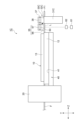
- FIG. 1 is a diagram illustrating a fusion splicer according to an embodiment.
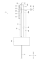
- FIG. 2 is a side view that typically illustrates an optical fiber holder, a rotating mechanism, and a clamp of the fusion splicer according to the embodiment.
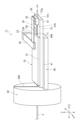
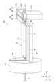
- FIG. 3 is a perspective view that typically illustrates an optical fiber holder, a rotating mechanism, and a clamp unit of the fusion splicer according to the embodiment.
- FIG. 4 is a side view showing the clamp portion and the light source of FIG.
- FIG. 5 is a plan view showing the clamp portion and the light source of FIG.
- FIG. 6 is a side view showing a clamp unit and a non-transparent material of a fusion splicer according to a first modified example.
- FIG. 1 is a diagram illustrating a fusion splicer according to an embodiment.
- FIG. 2 is a side view that typically illustrates an optical fiber holder, a rotating mechanism, and a clamp of the fusion splicer according to the embodiment
- FIG. 7 is a front view showing a clamp unit and a non-transparent material of a fusion splicer according to a first modified example.
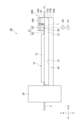
- FIG. 8 is a side view diagrammatically showing an optical fiber holder, a rotating mechanism, and a clamp unit of a fusion splicer according to a second modified example.
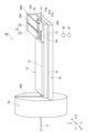
- FIG. 9 is a perspective view that typically shows an optical fiber holder, a rotating mechanism, and a clamp unit of a fusion splicer according to a second modified example.
- FIG. 10 is a side view diagrammatically showing an optical fiber holder, a rotating mechanism, and a clamp unit of a fusion splicer according to a third modified example.
- FIG. 11 is a perspective view that typically shows an optical fiber holder, a rotating mechanism, and a clamp unit of a fusion splicer according to a third modified example.
- FIG. 12 is a side view of a fusion splicer according to the fourth modified example.
- FIG. 13 is a plan view of a fusion splicer according to the fourth modified example.
- a light source such as the aforementioned epi-illumination illuminates the optical fiber to illuminate the end face of the optical fiber
- a method is known in which light is incident on the optical fiber from the end face opposite the end face that is illuminated.
- the light may not reach the end face that is illuminated, particularly when the optical fiber is long. As a result, the end face of the optical fiber may not be illuminated sufficiently.
- the objective of this disclosure is to provide a fusion splicer that can sufficiently illuminate the end face of an optical fiber.
- a fusion splicer includes: (1) an optical fiber holder that holds an optical fiber, a rotation mechanism that rotates the optical fiber holder about an axis extending along the optical fiber as a central axis, a clamping section that is disposed on the opposite side of the rotation mechanism as viewed from the optical fiber holder in the direction along the central axis and that holds the optical fiber held by the optical fiber holder, a light source that irradiates light onto the clamping section, and a power supplying section that supplies power to the light source.
- a tip of the optical fiber protrudes from the clamping section.
- the clamping section has a transparent section that is transparent to light and transmits light to the optical fiber.
- an optical fiber holder holds the optical fiber, and a rotation mechanism rotates the optical fiber holder.
- the fusion splicer has a clamping part that holds the optical fiber, and the clamping part is located on the opposite side of the optical fiber holder from the rotation mechanism.
- the fusion splicer has a light source that irradiates light onto the clamping part.
- the tip of the optical fiber protrudes from the clamping part.
- the clamping part has a transparent part that is transparent to the light from the light source and transmits the light into the optical fiber.
- the light that transmits through the transparent part of the clamping part enters the optical fiber and propagates to the tip of the optical fiber. Therefore, the end face of the optical fiber located at the tip of the optical fiber can be made to shine sufficiently.
- "Sufficiently shine" means to shine enough to be photographed by a camera.
- the clamping portion may have a non-transparent portion on at least a portion other than the surface where the light from the light source enters and the surface facing the optical fiber. In this case, it is possible to prevent light from leaking from the non-transparent portion provided on at least a portion other than the surface where the light from the light source enters and the surface facing the optical fiber. Therefore, it is possible to prevent stray light generated in the transparent portion from escaping from the clamping portion.
- the non-transparent portion may be a reflective material that reflects light.
- the light reflected by the reflective material can be made incident on the optical fiber, making the end face of the optical fiber brighter.
- the clamping section may have an optical path changing section that changes the optical path of the light inside the clamping section.
- the optical path changing section changes the optical path of the light inside the clamping section, so that more light can be guided to the portion of the optical fiber held by the clamping section. Therefore, the end face of the optical fiber can be made brighter.
- At least a part of the surface of the clamping section facing the optical fiber may be a highly reflective surface.
- light that reaches the optical fiber from the light source via the clamping section is reflected by the highly reflective surface and enters the optical fiber again. Therefore, the light irradiated from the light source can be confined in the optical fiber, making the end face of the optical fiber brighter.
- the clamping unit may have a base on which the optical fiber is placed, and a lid that covers the optical fiber placed on the base.
- the base may have a first surface that faces away from the light source in a direction along its central axis
- the lid may have a second surface that faces away from the light source in a direction along its central axis.
- the fusion splicer may further include a non-transparent material that extends from the second surface toward the first surface and closes a gap formed between the lid and the base. In this case, by closing the gap formed between the lid and the base with a non-transparent material, it is possible to prevent light from leaking from the gap to the tip of the optical fiber. Therefore, it is possible to capture a clearer image of the end face of the optical fiber.
- the fusion splicer may include a holder stand on which the optical fiber holder is mounted.
- the optical fiber holder may be removable from the holder stand.
- the fusion splicer includes a holder stand, and the optical fiber holder is removable from the holder stand. Since the optical fiber holder is removable from the holder stand, the optical fiber can be easily attached to and detached from the rotating mechanism.
- FIG. 1 is a diagram for explaining an overview of the fusion splicer 1 according to this embodiment.
- the fusion splicer 1 fusion-splices a pair of optical fibers F together.
- the fusion splicer 1 has an optical fiber holder 10 having a V-groove 11, and a rotation mechanism 20 that rotates the optical fiber holder 10.
- the axes of the pair of optical fibers F coincide with each other.
- the "axis" refers to the center line of the optical fiber that passes through the center of the optical fiber and extends along the direction in which the optical fiber extends.
- the optical fiber holder 10 and the rotation mechanism 20 are aligned along the axial direction, which is the direction in which the axis of the optical fiber F extends.
- the axial direction of the optical fiber F is the Z axis direction.
- the fusion splicer 1 includes a pair of optical fiber holders 10 aligned along the Z axis direction, which is the direction in which each of the pair of optical fibers F extends, and a pair of rotation mechanisms 20 aligned along the Z axis direction.
- the optical fiber F to be fusion spliced is positioned in the V groove 11 of each optical fiber holder 10.
- the optical fiber holder 10 is made of metal, for example.
- the optical fiber holder 10 holds, for example, a coated portion of the optical fiber F.
- the optical fiber holder 10 holds the tip F1 of the optical fiber F in a state in which it protrudes in the Z axis direction.
- the rotation mechanism 20 is arranged on the opposite side of the tip F1 of the optical fiber F from the optical fiber holder 10.
- a pair of discharge electrodes 2 are arranged at positions where the tips F1 of the pair of optical fibers F face each other.
- the pair of discharge electrodes 2 are arranged at positions where they face each other along a direction (e.g., the X-axis direction) that intersects with the optical fibers F.
- the optical fiber holder 10 has a base 12 on which the optical fibers F are placed and in which a V-groove 11 extending along, for example, the Z-axis direction is formed, and a lid 13 that is placed on the base 12.
- the base 12 and the lid 13 are arranged, for example, so as to be aligned along the Y-axis direction that intersects both the X-axis direction and the Z-axis direction.
- the pair of discharge electrodes 2 fusion-splices the tips F1 of the pair of optical fibers F together by discharge.
- the fusion splicer 1 has a control unit 3 that controls each part of the fusion splicer 1.
- the control unit 3 controls the discharge current and discharge time of the discharge electrodes 2, so that fusion splicing is performed under fusion conditions suited to the type of optical fiber F.
- the control unit 3 aligns the pair of optical fibers F.
- the control unit 3 adjusts the position of each optical fiber F in the X-axis direction and the Y-axis direction, and also aligns the pair of optical fibers F so that they are aligned in a straight line along the Z-axis direction. That is, the control unit 3 aligns the pair of optical fibers F in the X-axis direction, the Y-axis direction, and the Z-axis direction.
- the control unit 3 aligns the optical fibers F in the ⁇ direction by controlling the rotation mechanism 20 to rotate the optical fibers F around an axis (which is the same as the Z-axis in the figure) that extends along the center of the optical fibers F.
- the optical fiber F is, for example, an optical fiber that requires rotational alignment in the fusion splicer 1.
- the optical fiber F is an optical fiber that requires the positions of the core, cladding, markers, etc. in the ⁇ direction of a pair of optical fibers F to be aligned.
- the optical fiber F is a multi-core optical fiber (MCF: Multi Core Fiber) or a polarization maintaining fiber (PMF: Polarization Maintaining Fiber).
- FIG. 2 is a side view showing the configuration around the optical fiber holder 10.
- FIG. 3 is a perspective view showing the configuration around the optical fiber holder 10.
- the fusion splicer 1 includes a clamp unit 30 that holds the tip F1 of the optical fiber F held by the optical fiber holder 10, a holder base 40 fixed to the rotation mechanism 20, and a light source 50.
- the base 12 of the optical fiber holder 10 protrudes in the Z-axis direction beyond the lid 13.
- the portion of the optical fiber F that is held by the clamping portion 30 is, for example, a coated portion of the optical fiber F.
- the portion that is held by the clamping portion 30 may also be the portion of the optical fiber F from which the coating has been removed (for example, the portion from which the glass of the optical fiber F is exposed).
- the length of the portion of the optical fiber F that protrudes from the clamping portion 30 is, for example, 5 mm or less.
- the holder base 40 is made of metal, for example.
- the holder base 40 has a mounting surface 41 on which the optical fiber holder 10 is mounted.
- the optical fiber holder 10 is removable from the holder base 40.
- the optical fiber holder 10 removed from the holder base 40 holds the optical fiber F, and the optical fiber holder 10 holding the optical fiber F can be mounted on the holder base 40.
- the holder base 40 extends from the rotation mechanism 20 in the Z-axis direction.
- the rotation mechanism 20 is disposed on the opposite side of the tip F1 (end face) when viewed from the optical fiber holder 10.
- the rotation mechanism 20 has, for example, a recess 20b into which the optical fiber F is inserted.
- the recess 20b has a slit shape recessed along the Y-axis direction from the outer peripheral surface of the rotation mechanism 20.
- the rotation mechanism 20 rotates the optical fiber F together with the holder base 40 and the optical fiber holder 10, for example, around an axis extending along the center of the optical fiber F.
- the rotation mechanism 20 includes, for example, a motor (not shown) and a gear (not shown).
- the motor of the rotation mechanism 20 is driven and the rotational driving force of the motor is transmitted to the holder base 40 and the optical fiber holder 10 via the gear, causing the holder base 40 and the optical fiber holder 10 to rotate.
- the optical fiber F is inserted into the recess 20b of the rotation mechanism 20 and is held by the optical fiber holder 10. Therefore, as the holder base 40 and the optical fiber holder 10 are rotated by the rotation mechanism 20, the clamp section 30 and the optical fiber F rotate.
- the clamp unit 30 is provided to hold the optical fiber F protruding from the optical fiber holder 10.
- the clamp unit 30 has, for example, a base 31 on which the optical fiber F is placed, and a lid 32 that covers the optical fiber F placed on the base 31.
- the clamp unit 30 holds the optical fiber F by clamping the optical fiber F extending from the optical fiber holder 10 in the Z-axis direction between the base 31 and the lid 32.
- the base 31 is a portion that protrudes in the Z-axis direction from the base 12 of the optical fiber holder 10.
- the end face 31c of the base 31 located opposite the rotation mechanism 20 protrudes in the Z-axis direction further than the end face 13b of the lid 13 located opposite the rotation mechanism 20 and the end face 40b of the holder base 40 located opposite the rotation mechanism 20.
- a V-groove 31g in which the optical fiber F is placed is formed in a part of the upper surface 31b of the base 31.
- the V-groove 31g is a groove that has a V-shaped cross section in the XY plane in Figures 3 and 5 and extends in the Z direction.
- the optical fiber F placed in the V-groove 31g is sandwiched between the upper surface of the V-groove 31g and the lower surface 32b of the lid 32.
- the clamp unit 30 has a first portion 33 that protrudes from the holder base 40 in the Y-axis direction, a second portion 34 that extends from the first portion 33 in the X-axis direction and is located above the lid 13, and a third portion 35 that extends from the second portion 34 in the Z-axis direction.
- the lid 32 protrudes downward at the end of the third portion 35 opposite the second portion 34.
- Downward refers to the direction in which the clamp unit holds the optical fiber
- upward refers to the opposite direction to downward.
- the light source 50 is disposed adjacent to the base 31 and the lid 32.
- the light source 50 is disposed above the base 12.
- the light source 50 is disposed between the lid 13 of the optical fiber holder 10 and the lid 32 of the clamp unit 30. In this embodiment, the light source 50 is fixed to the underside of the third portion 35.
- the light source 50 is an LED light source.
- the fusion splicer 1 includes a power source 61, and the light source 50 receives power from the power source 61 via a power supply unit 62 and emits light.
- the power supply unit 62 indicates a unit that supplies power to the light source 50, and indicates, for example, a part of the fusion splicer 1 that is electrically connected to the light source 50.
- the power supply unit 62 may be a wiring part of the fusion splicer 1 that is connected to a power source (for example, a household power source or a socket) when, for example, it is driven by an AC power source (the fusion splicer 1 does not have a battery or a battery).
- the power supply unit 62 may be a wiring part inside the fusion splicer 1 that is connected to the battery or the battery.
- the fusion splicer 1 may have a dedicated battery or battery to which the power supply unit 62 that supplies power to the light source 50 is connected.
- FIG. 4 is an enlarged side view of the clamp unit 30 and the light source 50.
- the light source 50 laterally introduces light L into the optical fiber F via the clamp unit 30.
- the light source 50 irradiates light L diagonally downward toward the clamp unit 30.
- the clamp unit 30 has a transparent portion 32g that is transparent to the light L.
- the transparent portion 32g is formed, for example, in the lid 32.
- the transparent portion 32g is formed in at least a part of the lid 32.
- the transparent portion 32g may be formed in the entire lid 32, or may be formed in a part of the lid 32. That is, the entire lid 32 may be the transparent portion 32g, or a part of the lid 32 may be the transparent portion 32g.
- the clamp unit 30 has a non-transparent portion 32j on at least a portion of the surface 32h where the light L enters the clamp unit 30 and on the bottom surface 32b facing the optical fiber F.
- the non-transparent portion 32j is disposed on the first side surface 32k of the lid 32 that faces the X-axis direction and extends in both the Y-axis direction and the Z-axis direction, and on the second side surface 32m that faces the opposite direction to the first side surface 32k.
- the non-transparent portion 32j is, for example, a reflective material that reflects the light L from the light source 50. In this case, at least a portion of the light L reflected at the non-transparent portion 32j enters the optical fiber F.
- the base 31 has an upper surface 31b facing the optical fiber F.
- the optical fiber F is sandwiched between the upper surface 31b of the base 31 and the lower surface 32b of the lid 32.
- the optical fiber F is sandwiched between a V-groove 31g formed in the upper surface of the base 31 and the lower surface 32b of the lid 32.
- At least a part of the surface of the upper surface 31b of the base 31 facing the optical fiber F may be a highly reflective surface 39.
- a highly reflective surface is a surface that has been processed to increase the reflectance of incident light, or a surface to which a film or the like is attached.
- a highly reflective surface is a surface that has been polished to a mirror finish.
- a highly reflective surface may be a surface to which a reflective material is attached.
- the highly reflective surface 39 is a polished surface.
- a polished surface is a surface that has been polished.
- the highly reflective surface 39 is a surface that has been polished with an abrasive.
- the top surface 31b of the base 31 including the V-groove 31g may be the highly reflective surface 39.
- the light L that enters the lid 32 propagates inside the optical fiber F while being reflected by the top surface 31b of the base 31 including the V-groove 31g. Therefore, the light L can be more reliably transmitted to the tip F1 (end surface) of the optical fiber F.
- the upper surface 31b of the base 31 including the V-groove 31g is the highly reflective surface 39.
- a portion of the V-groove 31g may be the highly reflective surface 39.
- the optical fiber holder 10 holds the optical fiber F
- the rotation mechanism 20 rotates the optical fiber holder 10.
- the fusion splicer 1 has a clamping section 30 that holds the optical fiber F, and the clamping section 30 is disposed on the opposite side of the optical fiber holder 10 from the rotation mechanism 20.
- the fusion splicer 1 has a light source 50 that irradiates light L to the clamping section 30.
- the tip F1 of the optical fiber F protrudes from the clamping section 30.
- the clamping section 30 has a transparent section 32g that is transparent to the light L from the light source 50 and transmits the light L to the optical fiber F.
- the light that has transmitted through the transparent section 32g of the clamping section 30 enters the optical fiber F and propagates to the tip F1 of the optical fiber F. Therefore, the end face of the optical fiber F located at the tip F1 of the optical fiber F can be sufficiently illuminated.
- the clamp unit 30 may have a non-transparent portion 32j on at least a portion other than the surface 32h where the light L from the light source 50 enters and the bottom surface 32b facing the optical fiber F.
- a non-transparent portion 32j on at least a portion other than the surface 32h where the light L from the light source 50 enters and the bottom surface 32b facing the optical fiber F. Therefore, it is possible to prevent stray light generated in the transparent portion 32g from escaping from the clamp unit 30.
- the non-transparent portion 32j may be a reflective material that reflects light L.
- the light L reflected by the reflective material can be made incident on the optical fiber F, making the end face of the optical fiber F brighter.
- At least a part of the surface of the clamping unit 30 facing the optical fiber F may be a highly reflective surface 39.
- the light that reaches the optical fiber F from the light source 50 via the clamping unit 30 is reflected by the highly reflective surface 39 and enters the optical fiber F again. Therefore, the light L irradiated from the light source 50 can be confined in the optical fiber F, making the end face of the optical fiber F brighter.
- FIG. 6 is a side view showing the clamp unit 30A of the fusion splicer 1A according to the first modified example.
- FIG. 7 is a front view showing the clamp unit 30A.
- the clamp unit 30A has a base 31A and a lid 32A.
- the base 31A has a first surface 31f that faces away from the light source 50 in a direction along the central axis, with the axis line extending along the optical fiber F as the central axis.
- the lid 32A has a second surface 32f that faces away from the light source 50 in a direction along the central axis.
- the fusion splicer 1A has a non-transparent material 70 that fills the gap formed between the lid 32A and the base 31A.
- the non-transparent material 70 fills the gap formed between the lid 32A and the base 31A except for the portion from which the optical fiber F protrudes.
- the non-transparent material 70 is fixed to the second surface 32f of the lid 32A.
- the non-transparent material 70 extends from the second surface 32f toward the first surface 31f of the base 31A.
- FIG. 8 is a side view of the fusion splicer 1B according to the first modified example.
- FIG. 9 is a perspective view of the fusion splicer 1B.
- the clamp unit 30B has a base 31B and a lid 32.
- the base 31B has an end face 31d located opposite the rotation mechanism 20 in the direction along the central axis, with the axis line extending along the optical fiber F as the central axis.
- the end face 31d is a surface that is flush with the end face 40b of the holder base 40 located opposite the rotation mechanism 20.
- the clamp unit 30B has a first portion 33b protruding from the holder base 40 in the Y-axis direction, and a second portion 34b extending from the first portion 33 in the X-axis direction and located above the base 31B.
- the lid 32 protrudes downward at the second portion 34b.
- the light source 50 is held by a light source holding mechanism 51.
- the light source holding mechanism 51 has a third portion 52 that protrudes from the holder base 40 in the Y-axis direction, and a fourth portion 53 that extends from the third portion 52 in the X-axis direction and is located above the base 12.
- the light source 50 is fixed to the underside of the fourth portion 53.
- the light source 50 irradiates light L to the clamp portion 30B.
- the light L passes through the lid 32 and enters the optical fiber F.
- FIG. 10 is a side view of a fusion splicer 1C according to a third modified example.
- FIG. 11 is a perspective view of the fusion splicer 1C.
- the fusion splicer 1C differs from the fusion splicer 1 described above in that it has a clamping section 30C that is different from the clamping section 30, and in that the light source 50 does not rotate together with the optical fiber holder 10.
- the clamp unit 30C has a base 31C that is separate from the holder base 40, and a lid 32C that holds the optical fiber F placed on the base 31C.
- the lid 32C is held by a lid holding mechanism 36.
- the lid holding mechanism 36 has a first portion 37 that protrudes in the Y-axis direction relative to the base 31C, and a second portion 38 that extends in the X-axis direction from the first portion 37.
- the lid 32C is held by the underside of the second portion 38.
- the light source 50 is held by a light source holding mechanism 55 arranged adjacent to the lid holding mechanism 36.
- the light source 50 and the light source holding mechanism 55 are arranged between the optical fiber holder 10 and the clamp unit 30C.
- the light source holding mechanism 55 has a third portion 56 extending parallel to the first portion 37, and a fourth portion 57 extending from the third portion 56 in the X-axis direction.
- the light source 50 is held on the underside of the fourth portion 57.
- the fusion splicer 1C has a light source 50 arranged between the optical fiber holder 10 and the clamp unit 30C, and emits light L into the clamp unit 30C.
- the fusion splicer 1C provides the same effects as the fusion splicer 1 described above.
- FIG. 12 is a side view of a fusion splicer 1D according to a fourth modified example.
- FIG. 13 is a plan view of the fusion splicer 1D.
- the clamp unit 30D of the fusion splicer 1D has an optical path changing unit 32p that changes the optical path of the light L inside the clamp unit 30D.
- the optical path changing unit 32p is disposed inside the lid 32.
- the optical path changing section 32p is, for example, a lens.
- the light L from the light source 50 can be focused in the optical path changing section 32p and guided to the optical fiber F.
- the optical path changing section 32p may also be an optical waveguide that guides the light L to the optical fiber F.
- the optical path changing section 32p changes the optical path of the light L from the light source 50 inside the clamp section 30D, so that more light L can be guided to the portion of the optical fiber F held by the clamp section 30D. Therefore, the end face of the optical fiber F can be made brighter.
- each part of the fusion splicer can be modified as appropriate within the scope of the above-mentioned gist.
- the shape, size, number, material, and arrangement of each part of the fusion splicer according to the present disclosure are not limited to the above-mentioned embodiment or modifications, and can be modified as appropriate.
- the fusion splicer according to the present disclosure may be a combination of two or more of the above-mentioned embodiment, first modification, second modification, third modification, and fourth modification.
- the optical fiber holder 10 is detachable from the holder base 40.
- the optical fiber holder does not have to be detachable from the holder base.
- the fusion splicer does not have to have a holder base 40. In this case, the fusion splicer may have an optical fiber holder 10 fixed to the rotation mechanism 20.
Landscapes
- Physics & Mathematics (AREA)
- Engineering & Computer Science (AREA)
- Plasma & Fusion (AREA)
- General Physics & Mathematics (AREA)
- Optics & Photonics (AREA)
- Mechanical Coupling Of Light Guides (AREA)
Priority Applications (4)
| Application Number | Priority Date | Filing Date | Title |
|---|---|---|---|
| CN202480014593.9A CN120917353A (zh) | 2023-03-01 | 2024-03-01 | 熔接机 |
| JP2025504012A JPWO2024181568A1 (https=) | 2023-03-01 | 2024-03-01 | |
| EP24764045.1A EP4675323A1 (en) | 2023-03-01 | 2024-03-01 | Fusion splicer |
| KR1020257031219A KR20250143127A (ko) | 2023-03-01 | 2024-03-01 | 융착 접속기 |
Applications Claiming Priority (2)
| Application Number | Priority Date | Filing Date | Title |
|---|---|---|---|
| JP2023-031377 | 2023-03-01 | ||
| JP2023031377 | 2023-03-01 |
Publications (1)
| Publication Number | Publication Date |
|---|---|
| WO2024181568A1 true WO2024181568A1 (ja) | 2024-09-06 |
Family
ID=92590683
Family Applications (1)
| Application Number | Title | Priority Date | Filing Date |
|---|---|---|---|
| PCT/JP2024/007826 Ceased WO2024181568A1 (ja) | 2023-03-01 | 2024-03-01 | 融着接続機 |
Country Status (5)
| Country | Link |
|---|---|
| EP (1) | EP4675323A1 (https=) |
| JP (1) | JPWO2024181568A1 (https=) |
| KR (1) | KR20250143127A (https=) |
| CN (1) | CN120917353A (https=) |
| WO (1) | WO2024181568A1 (https=) |
Citations (9)
| Publication number | Priority date | Publication date | Assignee | Title |
|---|---|---|---|---|
| JP2001330749A (ja) * | 2000-05-22 | 2001-11-30 | Fujikura Ltd | 定偏波光ファイバ融着接続方法及びそのための融着接続機 |
| JP2004053625A (ja) | 2002-07-16 | 2004-02-19 | Mitsubishi Cable Ind Ltd | 光ファイバの接続方法及び光ファイバの接続装置 |
| JP2004126379A (ja) * | 2002-10-04 | 2004-04-22 | Furukawa Electric Co Ltd:The | Pm光ファイバ融着接続機及びpm光ファイバの融着接続方法 |
| WO2013077002A1 (ja) | 2011-11-21 | 2013-05-30 | 株式会社フジクラ | 光ファイバの融着接続方法 |
| JP2017021190A (ja) * | 2015-07-10 | 2017-01-26 | 三菱電線工業株式会社 | マルチコア光ファイバの接続方法 |
| US20200355878A1 (en) * | 2019-05-09 | 2020-11-12 | Afl Telecommunications Llc | Control systems and methods for aligning multimode optical fibers |
| WO2022244843A1 (ja) * | 2021-05-21 | 2022-11-24 | 住友電気工業株式会社 | 融着接続機 |
| WO2023013606A1 (ja) * | 2021-08-05 | 2023-02-09 | 住友電気工業株式会社 | 融着接続機 |
| JP2023031377A (ja) | 2021-08-25 | 2023-03-09 | 大阪瓦斯株式会社 | エンジンシステム |
-
2024
- 2024-03-01 EP EP24764045.1A patent/EP4675323A1/en active Pending
- 2024-03-01 JP JP2025504012A patent/JPWO2024181568A1/ja active Pending
- 2024-03-01 WO PCT/JP2024/007826 patent/WO2024181568A1/ja not_active Ceased
- 2024-03-01 KR KR1020257031219A patent/KR20250143127A/ko active Pending
- 2024-03-01 CN CN202480014593.9A patent/CN120917353A/zh active Pending
Patent Citations (9)
| Publication number | Priority date | Publication date | Assignee | Title |
|---|---|---|---|---|
| JP2001330749A (ja) * | 2000-05-22 | 2001-11-30 | Fujikura Ltd | 定偏波光ファイバ融着接続方法及びそのための融着接続機 |
| JP2004053625A (ja) | 2002-07-16 | 2004-02-19 | Mitsubishi Cable Ind Ltd | 光ファイバの接続方法及び光ファイバの接続装置 |
| JP2004126379A (ja) * | 2002-10-04 | 2004-04-22 | Furukawa Electric Co Ltd:The | Pm光ファイバ融着接続機及びpm光ファイバの融着接続方法 |
| WO2013077002A1 (ja) | 2011-11-21 | 2013-05-30 | 株式会社フジクラ | 光ファイバの融着接続方法 |
| JP2017021190A (ja) * | 2015-07-10 | 2017-01-26 | 三菱電線工業株式会社 | マルチコア光ファイバの接続方法 |
| US20200355878A1 (en) * | 2019-05-09 | 2020-11-12 | Afl Telecommunications Llc | Control systems and methods for aligning multimode optical fibers |
| WO2022244843A1 (ja) * | 2021-05-21 | 2022-11-24 | 住友電気工業株式会社 | 融着接続機 |
| WO2023013606A1 (ja) * | 2021-08-05 | 2023-02-09 | 住友電気工業株式会社 | 融着接続機 |
| JP2023031377A (ja) | 2021-08-25 | 2023-03-09 | 大阪瓦斯株式会社 | エンジンシステム |
Non-Patent Citations (1)
| Title |
|---|
| See also references of EP4675323A1 |
Also Published As
| Publication number | Publication date |
|---|---|
| CN120917353A (zh) | 2025-11-07 |
| JPWO2024181568A1 (https=) | 2024-09-06 |
| EP4675323A1 (en) | 2026-01-07 |
| KR20250143127A (ko) | 2025-09-30 |
Similar Documents
| Publication | Publication Date | Title |
|---|---|---|
| JP7819700B2 (ja) | 融着接続機 | |
| US12571965B2 (en) | Fusion splicing machine | |
| EP2711751A1 (en) | Method for distinguishing optical fiber and method for fusion-splicing optical fibers | |
| WO2023013591A1 (ja) | 融着接続機 | |
| WO2013077002A1 (ja) | 光ファイバの融着接続方法 | |
| CN1090330C (zh) | 熔接光纤的熔接设备 | |
| WO2023182224A1 (ja) | ファイバ融着接続装置およびファイバ融着接続方法 | |
| KR20210002688A (ko) | 검사 장치 | |
| WO2024181568A1 (ja) | 融着接続機 | |
| WO2024181567A1 (ja) | 融着接続機 | |
| JP4382694B2 (ja) | 光ファイバ融着接続機 | |
| WO2022239809A1 (ja) | 融着接続機 | |
| JP2024159235A (ja) | 融着機 | |
| JP2026067981A (ja) | 融着接続機 | |
| JP7748929B2 (ja) | 融着機 | |
| KR102064838B1 (ko) | 광섬유 융착접속기 | |
| JP3863976B2 (ja) | 基板検査装置 | |
| WO2025134821A1 (ja) | 融着接続機および融着接続方法 | |
| JP2544768B2 (ja) | 光ファイバの融着接続装置 | |
| JPH10332974A (ja) | 光ファイバ融着接続装置及び融着接続方法 | |
| WO2023120481A1 (ja) | 融着接続機 | |
| JPH01205108A (ja) | 光ファイバの融着接続装置 | |
| JPH11295035A (ja) | 電気部品検査用位置合わせ治具 | |
| JPS6352107A (ja) | 光フアイバの融着接続装置 |
Legal Events
| Date | Code | Title | Description |
|---|---|---|---|
| 121 | Ep: the epo has been informed by wipo that ep was designated in this application |
Ref document number: 24764045 Country of ref document: EP Kind code of ref document: A1 |
|
| ENP | Entry into the national phase |
Ref document number: 2025504012 Country of ref document: JP Kind code of ref document: A |
|
| WWE | Wipo information: entry into national phase |
Ref document number: 2025504012 Country of ref document: JP |
|
| WWE | Wipo information: entry into national phase |
Ref document number: 202480014593.9 Country of ref document: CN |
|
| ENP | Entry into the national phase |
Ref document number: 1020257031219 Country of ref document: KR Free format text: ST27 STATUS EVENT CODE: A-0-1-A10-A15-NAP-PA0105 (AS PROVIDED BY THE NATIONAL OFFICE) |
|
| WWE | Wipo information: entry into national phase |
Ref document number: 2024764045 Country of ref document: EP |
|
| NENP | Non-entry into the national phase |
Ref country code: DE |
|
| WWP | Wipo information: published in national office |
Ref document number: 202480014593.9 Country of ref document: CN |
|
| ENP | Entry into the national phase |
Ref document number: 2024764045 Country of ref document: EP Effective date: 20251001 |
|
| ENP | Entry into the national phase |
Ref document number: 2024764045 Country of ref document: EP Effective date: 20251001 |
|
| ENP | Entry into the national phase |
Ref document number: 2024764045 Country of ref document: EP Effective date: 20251001 |
|
| WWP | Wipo information: published in national office |
Ref document number: 2024764045 Country of ref document: EP |