WO2024180924A1 - コイル部品およびその製造方法 - Google Patents
コイル部品およびその製造方法 Download PDFInfo
- Publication number
- WO2024180924A1 WO2024180924A1 PCT/JP2024/000550 JP2024000550W WO2024180924A1 WO 2024180924 A1 WO2024180924 A1 WO 2024180924A1 JP 2024000550 W JP2024000550 W JP 2024000550W WO 2024180924 A1 WO2024180924 A1 WO 2024180924A1
- Authority
- WO
- WIPO (PCT)
- Prior art keywords
- straight pin
- pin member
- coil
- electrode terminal
- core
- Prior art date
- Legal status (The legal status is an assumption and is not a legal conclusion. Google has not performed a legal analysis and makes no representation as to the accuracy of the status listed.)
- Ceased
Links
Images


Classifications
-
- H—ELECTRICITY
- H01—ELECTRIC ELEMENTS
- H01F—MAGNETS; INDUCTANCES; TRANSFORMERS; SELECTION OF MATERIALS FOR THEIR MAGNETIC PROPERTIES
- H01F17/00—Fixed inductances of the signal type
- H01F17/04—Fixed inductances of the signal type with magnetic core
- H01F17/06—Fixed inductances of the signal type with magnetic core with core substantially closed in itself, e.g. toroid
-
- H—ELECTRICITY
- H01—ELECTRIC ELEMENTS
- H01F—MAGNETS; INDUCTANCES; TRANSFORMERS; SELECTION OF MATERIALS FOR THEIR MAGNETIC PROPERTIES
- H01F27/00—Details of transformers or inductances, in general
- H01F27/28—Coils; Windings; Conductive connections
-
- H—ELECTRICITY
- H01—ELECTRIC ELEMENTS
- H01F—MAGNETS; INDUCTANCES; TRANSFORMERS; SELECTION OF MATERIALS FOR THEIR MAGNETIC PROPERTIES
- H01F27/00—Details of transformers or inductances, in general
- H01F27/28—Coils; Windings; Conductive connections
- H01F27/29—Terminals; Tapping arrangements for signal inductances
-
- H—ELECTRICITY
- H01—ELECTRIC ELEMENTS
- H01F—MAGNETS; INDUCTANCES; TRANSFORMERS; SELECTION OF MATERIALS FOR THEIR MAGNETIC PROPERTIES
- H01F37/00—Fixed inductances not covered by group H01F17/00
-
- H—ELECTRICITY
- H01—ELECTRIC ELEMENTS
- H01F—MAGNETS; INDUCTANCES; TRANSFORMERS; SELECTION OF MATERIALS FOR THEIR MAGNETIC PROPERTIES
- H01F41/00—Apparatus or processes specially adapted for manufacturing or assembling magnets, inductances or transformers; Apparatus or processes specially adapted for manufacturing materials characterised by their magnetic properties
- H01F41/02—Apparatus or processes specially adapted for manufacturing or assembling magnets, inductances or transformers; Apparatus or processes specially adapted for manufacturing materials characterised by their magnetic properties for manufacturing cores, coils, or magnets
- H01F41/04—Apparatus or processes specially adapted for manufacturing or assembling magnets, inductances or transformers; Apparatus or processes specially adapted for manufacturing materials characterised by their magnetic properties for manufacturing cores, coils, or magnets for manufacturing coils
- H01F41/10—Connecting leads to windings
Definitions
- This disclosure relates to coil components and methods for manufacturing the same.
- a conventional coil component is described in JP 2021-150314 A (Patent Document 1).
- This coil component has an annular core, a resin cap that covers part of the core, and a coil wound around the core and the cap.
- the coil includes multiple straight pin members and multiple bent pin members, and the straight pin members and bent pin members are alternately connected to form a coil spiral, and the multiple straight pin members include an endmost straight pin member that is located at the axial end of the coil.
- the most end straight pin member is connected to the bent pin member in a cantilevered state, which can cause the posture of the most end straight pin member to become unstable, and the connection between the most end straight pin member and the bent pin member to become unstable. This can reduce the reliability of the connection between the most end straight pin member and the bent pin member.
- the second end of the most-end straight pin member is connected to the bent pin member by welding or the like while the first end of the most-end straight pin member is not restrained, so the most-end straight pin member is connected to the bent pin member in an unstable position. This may reduce the reliability of the connection between the most-end straight pin member and the bent pin member.
- the objective of this disclosure is to provide a coil component and a manufacturing method thereof that can improve the connection reliability between the endmost straight pin member and the bent pin member.
- a coil component comprises: An annular core; A core cover portion that covers at least a portion of the core; A coil is wound around the core and the core cover, the core has a first end surface and a second end surface opposed to each other in a central axis direction, the core cover portion has a first portion facing the first end surface, the first portion having a protrusion on a first surface opposite the first end surface, the coil includes a plurality of straight pin members and a plurality of bent pin members, the straight pin members and the bent pin members being alternately connected to form a spiral of the coil, and the plurality of straight pin members include an endmost straight pin member located at an end on at least one side of the axial direction of the coil, The endmost straight pin member faces the first surface of the first portion, a first end of the endmost straight pin member contacts the protrusion portion, and a second end of the endmost straight pin member is spaced from the first surface and connected to the bent pin member.
- the most-end straight pin member faces the first surface of the first portion, the first end of the most-end straight pin member contacts the protrusion, and the second end of the most-end straight pin member is connected to the folded pin member away from the first surface.
- the first end of the most-end straight pin member is supported by the protrusion, and the second end of the most-end straight pin member is supported by the folded pin member.
- the most-end straight pin member is connected to the folded pin member in a double-supported beam state. Therefore, the posture of the most-end straight pin member is stable, and the connection state between the most-end straight pin member and the folded pin member is stable. Therefore, the connection reliability between the most-end straight pin member and the folded pin member is improved.
- the second end of the most-end straight pin member can be connected to the bent pin member by welding or the like while the first end of the most-end straight pin member is supported on the protrusion, and the most-end straight pin member can be connected to the bent pin member in a stable position. This improves the connection reliability between the most-end straight pin member and the bent pin member.
- the heat generated when connecting the most distal straight pin member and the bent pin member by welding or the like is less likely to propagate to the core cover portion, reducing deterioration of the core cover portion due to heat.
- the coil component further comprising an electrode terminal connected to the coil;
- the endmost straight pin member is connected to the electrode terminal.
- the most-end straight pin member is connected to the electrode terminal.
- the posture of the most-end straight pin member is stable, and the connection state between the most-end straight pin member and the electrode terminal is stable. Therefore, the connection reliability between the most-end straight pin member and the electrode terminal is improved.
- the first end of the outermost straight pin member is connected to the electrode terminal.
- the first end of the most-end straight pin member is connected to the electrode terminal while being supported by the protrusion. This allows the electrode terminal to be connected to the first end in a stable position, making the connection between the most-end straight pin member and the electrode terminal more stable. Furthermore, when the electrode terminal is connected to the first end of the most-end straight pin member by welding or the like, the pressing force applied to the first end can be received by the protrusion, reducing the load on the first end.
- the protrusion preferably overlaps the electrode terminal when viewed in a direction perpendicular to the first surface.
- the electrode terminal is connected to the first end in a more stable position, so the connection state between the most-end straight pin member and the electrode terminal is more stable.
- the electrode terminal is connected to the first end of the most-end straight pin member by welding or the like, the load caused by the pressing force on the first end can be further reduced.
- the second end of the outermost straight pin member is connected to the electrode terminal.
- the second end of the most-end straight pin member is spaced from the first surface, so that the heat generated when connecting the most-end straight pin member and the electrode terminal by welding or the like is less likely to propagate to the core cover portion, thereby reducing deterioration of the core cover portion due to heat.
- the protrusion is preferably spaced apart from the electrode terminal when viewed in a direction perpendicular to the first surface.
- the heat is less likely to propagate through the protrusion and less likely to propagate through the core cover.
- the endmost straight pin member and the electrode terminal are preferably connected by welding.
- the endmost straight pin member and the electrode terminal are connected by welding, which improves the connection strength compared to connections made by soldering.
- a mounting portion for mounting the electrode terminal is further provided.
- the core cover portion and the mounting base portion are an integrated, one-piece molded product.
- the core cover and the mounting base are integrated, so the core stored in the core cover is supported by the mounting base, stabilizing the position of the core.
- the number of parts that make up the coil component can be reduced, simplifying the manufacturing process of the coil component.
- the step of arranging the straight pin members and the bent pin members includes: placing an endmost straight pin member located at an end on at least one side of the axial direction of the coil among the plurality of straight pin members against the first surface; and contacting a first end of the endmost straight pin member with a protrusion provided on the first surface;
- the process of forming the coil includes supporting the first
- the second end of the most-end straight pin member can be connected to the bent pin member, and the most-end straight pin member can be connected to the bent pin member in a stable position. Therefore, the connection reliability between the most-end straight pin member and the bent pin member is improved.
- the heat generated when connecting the most distal straight pin member and the bent pin member by welding or the like is less likely to propagate to the core cover portion, reducing deterioration of the core cover portion due to heat.
- the method further includes a step of connecting an electrode terminal to the endmost straight pin member and connecting the electrode terminal to the coil.
- the most-end straight pin member is connected to the electrode terminal.
- the posture of the most-end straight pin member is stable, and the connection state between the most-end straight pin member and the electrode terminal is stable. Therefore, the connection reliability between the most-end straight pin member and the electrode terminal is improved.
- the step of forming the coil includes connecting the ends of each of the straight pin members and each of the bent pin members with each of the straight pin members and each of the bent pin members while the straight pin members and each of the bent pin members are fitted into grooves in a jig.
- the straight pin members and the bent pin members can be connected while being positioned, improving the connection reliability of the straight pin members and the bent pin members.
- the step of forming the coil includes connecting the ends of each of the straight pin members and the ends of each of the bent pin members while exposing the ends of each of the straight pin members and the ends of each of the bent pin members through holes in the jig.
- all straight pin members and all bent pin members can be connected in one step while the jig is still attached.
- the step of forming the coil includes connecting an end of each of the straight pin members and an end of each of the bent pin members in a state in which the straight pin members and the bent pin members are fitted into grooves of a jig;
- the step of connecting the electrode terminal includes connecting the electrode terminal to the end straight pin member in a state in which a positioning protrusion of the jig is inserted into a slit portion of the electrode terminal.
- the straight pin members and the bent pin members can be connected while being positioned, improving the connection reliability between the straight pin members and the bent pin members.
- the electrode terminal can be connected to the end straight pin member while being positioned, improving the connection reliability between the end straight pin member and the electrode terminal.
- the step of forming the coil includes connecting the ends of the straight pin members and the ends of the bent pin members while exposing the ends of the straight pin members and the ends of the bent pin members from holes in the jig;
- the step of forming the electrode terminal includes connecting the electrode terminal to the endmost straight pin member while exposing the endmost straight pin member and the electrode terminal from the hole of the jig.
- connection between the straight pin member and the bent pin member, and the connection between the end straight pin member and the electrode terminal can be performed in one step while the jig is still attached.
- the coil component and manufacturing method thereof which are one aspect of the present disclosure, can improve the connection reliability between the endmost straight pin member and the bent pin member.
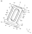
- FIG. 2 is a top perspective view showing the coil component of the first embodiment.
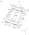
- FIG. FIG. 2 is a bottom perspective view showing the inside of the coil component.
- FIG. FIG. 2 is a schematic cross-sectional view of a coil component.
- 6 is a cross-sectional view taken along line VI-VI of FIG. 13 is a top perspective view of a connection portion between an endmost straight pin member and a bent pin member in the first coil.
- FIG. FIG. FIG. FIG. 4 is a bottom view of the coil component excluding the bottom plate portion.
- 11 is a cross-sectional view taken along the line XI-XI of FIG.
- FIG. 2 is a perspective view of a jig used in the manufacturing method of the coil component.
- FIG. 11 is a bottom view showing a state in which a jig is used in the manufacturing method of the coil component.
- FIG. 14 is a perspective view of FIG. 13 with the core and base case omitted.
- Fig. 1 is an upper perspective view showing a coil component according to an embodiment of the present invention.
- Fig. 2 is a lower perspective view of the coil component.
- Fig. 3 is a lower perspective view showing the inside of the coil component.
- Fig. 4 is an exploded perspective view of the coil component.
- the coil component 1 has an annular core 3, a base case 22 covering at least a part of the core 3, a first coil 41 and a second coil 42 wound around the core 3 and the base case 22, first to fourth electrode terminals 51 to 54 attached to the base case 22, and a bottom plate portion 21 attached to the base case 22.
- the coil component 1 is, for example, a common mode choke coil.
- the base case 22 and the bottom plate 21 are made of a material that is strong and heat resistant, and preferably flame retardant.
- the base case 22 is made of a resin such as PPS (polyphenylene sulfide), LCP (liquid crystal polymer), or PPA (polyphthalamide), or ceramics.
- the base case 22 has a core cover part 60 that covers at least a portion of the core 3, a first mounting part 71 to which the first and third electrode terminals 51, 53 are attached, and a second mounting part 72 to which the second and fourth electrode terminals 52, 54 are attached.
- the core cover part 60, the first mounting part 71, and the second mounting part 72 are an integrated, one-piece molded product.
- the core cover part 60 is an annular container body. Specifically, the core cover part 60 has an inner periphery 60a, an outer periphery 60b, and a bottom 60c.
- the core cover part 60 has an annular recess 61 that covers the lower part of the core 3.
- the annular recess 61 is a space surrounded by the inner periphery 60a, the outer periphery 60b, and the bottom 60c.
- the core cover part 60 (annular recess 61) is an oval (track-shaped) annular body.
- the shape of the core cover part 60 may be rectangular, elliptical, or circular.
- the first mounting base 71 and the second mounting base 72 are formed in a rectangular parallelepiped flange shape and are located on both sides of the core cover part 60. Specifically, the first mounting base 71 and the second mounting base 72 are located radially outside the core cover part 60. In this embodiment, the first mounting base 71 and the second mounting base 72 are located longitudinally outside the annular recess 61.
- the first mounting base 71 has a slit hole 70 into which the first and third electrode terminals 51, 53 are inserted.
- the second mounting base 72 has a slit hole 70 into which the second and fourth electrode terminals 52, 54 are inserted.
- the bottom plate portion 21 has a bottom portion 210, two side wall portions 211, and a partition wall portion 212.
- the bottom portion 210 includes a first main surface 210a and a second main surface 210b that face each other.
- the two side wall portions 211 are provided on the first main surface 210a of the bottom portion 210 along each of a pair of opposing sides of the bottom portion 210.
- the partition wall portion 212 is provided between the two side wall portions 211 on the first main surface 210a of the bottom portion 210.
- the bottom plate portion 21 has a recess 215, and the recess 215 is surrounded by the bottom portion 210, the side wall portion 211, and the partition wall portion 212.
- the bottom plate portion 21 is attached to the bottom 60c side of the core cover portion 60.
- the bottom plate portion 21 is attached to the base case 22 so that the central axis of the core 3 is perpendicular to the first main surface 210a of the bottom portion 210.
- the central axis of the core 3 refers to the central axis of the inner diameter hole portion of the core 3.
- the shape of the bottom plate portion 21 is rectangular when viewed from the central axis direction of the core 3. In this embodiment, the shape of the bottom plate portion 21 is rectangular when viewed from the central axis direction of the core 3.
- the direction in which the first mounting base 71 and the second mounting base 72 face each other as viewed from the central axis direction of the core 3 is the Y direction
- the direction perpendicular to the Y direction as viewed from the central axis direction of the core 3 is the X direction
- the height direction of the coil component 1, which is perpendicular to both the X and Y directions is the Z direction.
- the bottom plate 21 and the base case 22 are arranged facing each other in the Z direction, with the bottom plate 21 on the lower side and the base case 22 on the upper side, with the upper side being the forward direction of the Z direction and the lower side being the reverse direction of the Z direction.
- the direction from the first main surface 210a toward the core 3 is the upward direction.
- the Y direction is the long axis direction of the core cover part 60
- the X direction is the short axis direction of the core cover part 60.
- the first to fourth electrode terminals 51 to 54 are attached to the base case 22.
- the first electrode terminal 51 and the second electrode terminal 52 are located at two corners of the base case 22 that face each other in the Y direction
- the third electrode terminal 53 and the fourth electrode terminal 54 are located at two corners of the base case 22 that face each other in the Y direction.
- the first electrode terminal 51 and the third electrode terminal 53 face each other in the X direction
- the second electrode terminal 52 and the fourth electrode terminal 54 face each other in the X direction.
- the first and third electrode terminals 51, 53 are each inserted into a slit hole 70 in the first mounting base 71 and attached.
- the second and fourth electrode terminals 52, 54 are each inserted into a slit hole 70 in the second mounting base 72 and attached.
- the first to fourth electrode terminals 51-54 are each a metal plate bent into a U-shape. One end of each of the first to fourth electrode terminals 51-54 is inserted into the slit hole 70 and connected to the coils 41, 42. One end of each of the first to fourth electrode terminals 51-54 has a slit portion 51a-54a. The other end of each of the first to fourth electrode terminals 51-54 is located outside the mounting bases 71, 72 and is connected to a mounting board (not shown).
- a dummy terminal 55 is attached to the second main surface 210b of the bottom plate portion 21.
- the dummy terminal 55 is adhered to the second main surface 210b with an adhesive or the like.
- the dummy terminal 55 is not electrically connected to the first coil 41 and the second coil 42.
- the core 3 is a toroidal core, and is an elliptical (track-shaped) ring-shaped body when viewed from the central axis direction.
- the core 3 When viewed from the central axis direction, the core 3 includes a pair of long portions 31 that extend along the long axis and face each other in the short axis direction, and a pair of short portions 32 that extend along the short axis and face each other in the long axis direction.
- the shape of the core 3 may be rectangular, elliptical, or circular when viewed from the central axis direction.
- the core 3 is composed of, for example, a ceramic core such as ferrite, or a magnetic core made of iron-based powder molding or nanocrystalline foil.
- the core 3 has a first end face 301 and a second end face 302 that face each other in the central axis direction, and an inner peripheral surface 303 and an outer peripheral surface 304.
- the first end face 301 is the lower end face of the core 3 and is located on the bottom plate portion 21 side.
- the second end face 302 is the upper end face of the core 3.
- the short portion 32 has a convex portion on the second end face 302. In other words, the region of the second end face 302 that is located on the short portion 32 is located higher in the Z direction than the region of the second end face 302 that is located on the long portion 31.
- the shape of a cross section perpendicular to the circumferential direction as viewed from the central axis direction of core 3 is rectangular.
- First end face 301 and second end face 302 are disposed perpendicular to the central axis direction of core 3.
- Inner peripheral surface 303 and outer peripheral surface 304 are disposed parallel to the central axis direction of core 3.
- perpendicular is not limited to a completely perpendicular state, but also includes a substantially perpendicular state.
- parallel is not limited to a completely parallel state, but also includes a substantially parallel state.
- the core 3 is stored in the core cover part 60 of the base case 22 so that the long axis direction of the core 3 coincides with the Y direction.
- a portion of the core 3 on the first end face 301 side is covered by the core cover part 60.
- the lower portion of the core 3 is fitted into the annular recess 61 of the core cover part 60, so that the core 3 can be attached to the core cover part 60.
- the core 3 is connected to the core cover part 60 via a core adhesive member 91.
- the core adhesive member 91 is disposed in the annular recess 61 and bonds the first end face 301 of the core 3 to the bottom part 60c of the core cover part 60.
- the first coil 41 and the second coil 42 are connected to the bottom plate portion 21 via a coil adhesive member 90.
- the coil adhesive member 90 is disposed in the recess 215 of the bottom plate portion 21 and contacts the first coil 41, the second coil 42, and the base case 22.
- the first coil 41 is wound around the core 3 and the core cover part 60 between the first electrode terminal 51 and the second electrode terminal 52. One end of the first coil 41 is connected to the first electrode terminal 51. The other end of the first coil 41 is connected to the second electrode terminal 52.
- the second coil 42 is wound around the core 3 and the core cover part 60 between the third electrode terminal 53 and the fourth electrode terminal 54. One end of the second coil 42 is connected to the third electrode terminal 53. The other end of the second coil 42 is connected to the fourth electrode terminal 54.
- the first coil 41 and the second coil 42 are wound spirally around the core 3 and the core cover part 60 along the circumferential direction of the core 3 as viewed from the central axis direction of the core 3. Specifically, the first coil 41 is wound around one longitudinal part 31 of the core 3 and the core cover part 60 along the longitudinal direction of the core 3, and the second coil 42 is wound around the other longitudinal part 31 of the core 3 and the core cover part 60 along the longitudinal direction of the core 3.
- the winding axis of the first coil 41 and the winding axis of the second coil 42 run parallel to each other.
- the first coil 41 and the second coil 42 are symmetrical with respect to the longitudinal axis of the core 3.
- the number of turns of the first coil 41 and the second coil 42 are the same.
- the winding direction of the first coil 41 around the core 3 is opposite to the winding direction of the second coil 42 around the core 3.
- the winding direction from the first electrode terminal 51 to the second electrode terminal 52 of the first coil 41 is opposite to the winding direction from the third electrode terminal 53 to the fourth electrode terminal 54 of the second coil 42.
- the first to fourth electrode terminals 51 to 54 are connected so that a common mode current flows from the first electrode terminal 51 to the second electrode terminal 52 in the first coil 41, and flows from the third electrode terminal 53 to the fourth electrode terminal 54 in the second coil 42; that is, the first to fourth electrode terminals 51 to 54 are connected so that the current flows in the same direction.
- a common mode current flows through the first coil 41
- a first magnetic flux is generated in the core 3 by the first coil 41.
- a common mode current flows through the second coil 42
- a second magnetic flux is generated in the core 3 in a direction in which the first magnetic flux and the core 3 reinforce each other. Therefore, the first coil 41 and the core 3, and the second coil 42 and the core 3 act as inductance components, and noise is eliminated from the common mode current.
- the first coil 41 is formed by connecting multiple pin members by welding, such as laser welding or spot welding.
- welding such as laser welding or spot welding.
- FIG. 3 does not show the multiple pin members actually welded together, but shows the multiple pin members assembled together.
- the method of connecting the multiple pin members is not limited to welding, and other connection methods using, for example, solder or a conductive adhesive material may also be used. In the following, to simplify the explanation, it will be explained that welding is used as the method of connecting the multiple pin members.
- the multiple pin members are rod-shaped members, not printed wiring or conductors.
- the pin members have rigidity. Specifically, in a cross section perpendicular to the circumferential direction of the core 3, the pin members are shorter than the length of one circumference of the core passing through the first end face 301, the second end face 302, the inner peripheral surface 303, and the outer peripheral surface 304 of the core 3, and are also highly rigid, making them difficult to bend.
- the multiple pin members include multiple bent pin members 410 bent into an approximately U-shape and multiple straight pin members 411, 412 extending in an approximately straight line. The straight pin members 411, 412 and the bent pin member 410 are alternately connected to form the spiral of the first coil 41.
- the multiple straight pin members 411, 412 include the most end straight pin member 411 located at the most end on at least one side of the axial direction of the first coil 41.
- the straight pin members other than the end straight pin member 411 are referred to as normal straight pin members 412 (hereinafter simply straight pin members 412).
- the first coil 41 includes, from one end to the other, an endmost straight pin member 411 on one end side (one side), multiple sets of bent pin members 410 and straight pin members 412, and an endmost straight pin member 411 on the other end side (the other side).
- the endmost straight pin member 411 and the straight pin member 412 have the same shape. However, this is not limited to this, and the endmost straight pin member 411 and the straight pin member 412 may have different shapes.
- the length in the extension direction of the endmost straight pin member 411 may be shorter than the length in the extension direction of the straight pin member 412.
- the spring index Ks of the folding pin member 410 is smaller than 3.6 at the radius of curvature R1 of the folding pin member 410 located at the corner of the outer peripheral surface 304 of the core 3 and the radius of curvature R2 of the folding pin member 410 located at the corner of the inner peripheral surface 303 of the core 3.
- the spring index Ks can be expressed as the radius of curvature R1, R2 of the folding pin member / the wire diameter r of the folding pin member. In this way, the folding pin member 410 has high rigidity and is difficult to bend.
- the bent pin members 410 and the straight pin members 412 are alternately connected by welding, for example, laser welding or spot welding.
- One end of the straight pin member 412 is connected to one end of the bent pin member 410, and the other end of the straight pin member 412 is connected to one end of the other bent pin member 410.
- multiple bent pin members 410 and straight pin members 412 are connected, and the multiple connected bent pin members 410 and straight pin members 412 are arranged in a spiral shape on the core 3. In other words, one set of bent pin members 410 and straight pin members 412 forms one turn.
- the bent pin member 410 is arranged parallel to each of the second end face 302, the inner peripheral face 303, and the outer peripheral face 304 of the core 3.
- the bent pin member 410 extends in the X direction with a virtual line connecting both ends of the bent pin member 410 in the extension direction slightly tilted in the Y direction when viewed from the central axis direction of the core 3.
- the bent pin member 410 is arranged such that a plane including the center line of the bent pin member 410 is slightly tilted in the Y direction with respect to a plane (XZ plane) perpendicular to the axial direction of the first coil 41.
- the straight pin member 412 is arranged parallel to the first end face 301 of the core 3.
- the straight pin member 412 extends in the X direction.
- the most end straight pin member 411 is arranged parallel to the first end face 301 of the core 3.
- the most end straight pin member 411 extends in a direction parallel to the straight pin member 412.
- the first electrode terminal 51 is connected to one of the endmost straight pin members 411, which is connected to one end of the bent pin member 410 of the adjacent turn to the endmost straight pin member 411. A portion of the first electrode terminal 51 faces the endmost straight pin member 411, and the peripheral surface of the endmost straight pin member 411 is connected to the first electrode terminal 51. Specifically, a portion of the first electrode terminal 51 passes through the slit hole 70 of the first mounting base portion 71 and is connected to the peripheral surface of the endmost straight pin member 411.
- the second electrode terminal 52 is connected to the other endmost straight pin member 411, which is connected to one end of the bent pin member 410 of the adjacent turn to the other endmost straight pin member 411.
- a portion of the second electrode terminal 52 faces the other endmost straight pin member 411, and the peripheral surface of the other endmost straight pin member 411 is connected to the second electrode terminal 52.
- a portion of the second electrode terminal 52 passes through the slit hole 70 of the second mounting base portion 72 and is connected to the peripheral surface of the other endmost straight pin member 411.
- the second coil 42 is composed of multiple pin members, similar to the first coil 41. That is, the second coil 42 includes, from one end to the other, an endmost straight pin member 421 on one end side (one side), multiple sets of bent pin members 420 and straight pin members 422, and an endmost straight pin member 421 on the other end side (the other side).
- the bent pin members 420 and straight pin members 422 are alternately connected and wound around the core 3. That is, the multiple bent pin members 420 and straight pin members 422 are connected, and the multiple connected bent pin members 420 and straight pin members 422 are wound spirally around the core 3.
- the third electrode terminal 53 is connected to one of the endmost straight pin members 421, which is connected to one end of the bent pin member 420 of the adjacent turn to the endmost straight pin member 421.
- a portion of the third electrode terminal 53 faces the endmost straight pin member 421, and the peripheral surface of the endmost straight pin member 421 is connected to the third electrode terminal 53.
- a portion of the third electrode terminal 53 passes through the slit hole 70 of the first mounting base portion 71 and is connected to the peripheral surface of the endmost straight pin member 421.
- the fourth electrode terminal 54 is connected to the other endmost straight pin member 421, which is connected to one end of the bent pin member 420 of the adjacent turn to the other endmost straight pin member 421.
- a portion of the fourth electrode terminal 54 faces the other endmost straight pin member 421, and the peripheral surface of the other endmost straight pin member 421 is connected to the fourth electrode terminal 54.
- a portion of the fourth electrode terminal 54 passes through the slit hole 70 of the second mounting base portion 72 and is connected to the peripheral surface of the other endmost straight pin member 421.
- the first coil 41 and the second coil 42 each include a conductor portion and a coating that covers a portion of the conductor portion.
- the conductor portion is, for example, a copper wire
- the coating is, for example, a polyamideimide resin.
- the thickness of the coating is, for example, 0.02 to 0.04 mm.
- the endmost straight pin members 411, 421 are composed of uncoated conductor portions 411a, 421a.
- the straight pin members 412, 422 are composed of uncoated conductor portions 412a, 422a.
- the bent pin members 410, 420 are composed of conductor portions 410a, 420a and coatings 410b, 420b.
- the conductor portions 410a, 420a are exposed from the coatings 410b, 420b.
- the endmost straight pin members 411, 421, the straight pin members 412, 422 and the bent pin members 410, 420 are welded to each other, for example, at the exposed conductor portions 411a, 421a, 412a, 422a, 410a, 420a.
- These conductor portions not covered by the coating i.e., the conductor portions exposed from the coating (without the coating), can be electrically connected to the outside.
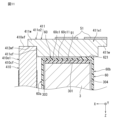
- FIG. 6 is a cross-sectional view taken along the line VI-VI in FIG. 1.
- the dummy terminal 55 is omitted.
- the ends of adjacent pin members in the first coil 41 have a welded portion where they are welded together.
- a welded portion refers to a portion that melts once during welding and then solidifies.
- the first coil 41 has a first welded portion 81 and a second welded portion 82.
- the straight pin member 412 and the bent pin member 410 of one turn form a first welded portion 81 where one conductor portion 412a of the straight pin member 412 and the conductor portion 410a of the bent pin member 410 are welded together, and the straight pin member 412 and the bent pin member 410 of the other turn form a second welded portion 82 where the other conductor portion 412a of the straight pin member 412 and the conductor portion 410a of the bent pin member are welded together.
- FIG. 6 shows a turn composed of the straight pin member 412 and the bent pin member 410 of the first coil 41, the same applies to a turn composed of the endmost straight pin member 411 and the bent pin member 410.
- the endmost straight pin member 411 is welded to the conductor portion 410a of the bent pin member 410 connected to the conductor portion 411a, forming the first welded portion 81 or the second welded portion 82.
- the second coil 42 has a third weld 83 and a fourth weld 84.
- the straight pin member 422 and the bent pin member 420 of one turn are welded at one conductor portion 422a of the straight pin member 422 and the conductor portion 420a of the bent pin member 420 to form the third weld 83
- the straight pin member 422 and the bent pin member 420 of the other turn are welded at the other conductor portion 422a of the straight pin member 422 and the conductor portion 420a of the bent pin member to form the fourth weld 84.
- the most end straight pin member 421 is welded at the conductor portion 420a of the bent pin member 420 connected to the conductor portion 421a to form the third weld 83 or the fourth weld 84.
- the third welded portion 83 and the fourth welded portion 84 of the second coil 42 have the same configuration as the first welded portion 81 and the second welded portion 82 of the first coil 41, and their description will be omitted.
- the core cover portion 60 is located between the conductor portions and welded portions of the coils 41, 42 that are exposed from the coating and the core 3. This allows for more reliable insulation between the conductor portions and welded portions of the coils 41, 42 and the core 3.
- the core cover part 60 is provided over the first end face 301 of the core 3, a part of the inner peripheral surface 303 of the core 3, and a part of the outer peripheral surface 304 of the core 3.
- the core cover part 60 has an inner peripheral part 60a facing the inner peripheral surface 303 of the core 3, an outer peripheral part 60b facing the outer peripheral surface 304 of the core 3, and a bottom part 60c facing the first end face 301 of the core 3.
- the bottom part 60c corresponds to an example of the "first part" described in the claims.
- the bottom part 60c has a first surface 60c1 opposite the first end face 301.
- the core 3 is connected to the core cover part 60 via the core adhesive member 91.
- the core adhesive member 91 By connecting the core adhesive member 91 to a part of the core 3, the stress on the core 3 received from the core cover part 60 is reduced, and deterioration of the magnetic properties of the core 3 can be suppressed. In other words, a decrease in the inductance value caused by magnetostriction can be suppressed.
- the core cover part 60 may not be connected to the core 3 via the core adhesive member 91, and may simply be fitted into the core 3.
- the core adhesive member 91 is provided between the first end face 301 of the core 3 and the bottom 60c of the core cover part 60. This makes it possible to reduce the effect of magnetostriction on the core 3 while stably attaching the core cover part 60 to the core 3.
- the material of the core adhesive member 91 can be soft resin such as urethane resin or silicone resin. By using such soft resin, the effect of magnetostriction can be reduced.
- the core adhesive member 91 is provided over the entire area between the first end face 301 of the core 3 and the bottom 60c of the core cover part 60, but it may be provided only in a portion of the area. Also, in FIG. 6, the core adhesive member 91 is provided between the first end face 301 of the core 3 and the bottom 60c of the core cover part 60, but it may be provided between the inner circumferential surface 303 of the core 3 and the inner circumferential portion 60a of the core cover part 60, or between the outer circumferential surface 304 of the core 3 and the outer circumferential portion 60b of the core cover part 60, or it may be provided in multiple locations among these.
- the conductor portions exposed from the coating of the coils 41, 42 are disposed in the recess 215 so as to be located on the first main surface 210a side.
- the coil adhesive member 90 is fixed in the recess 215 to adhere the coils 41, 42 to the bottom plate portion 21 and cover at least a portion of the conductor portions exposed from the coating of the coils 41, 42.
- the coil adhesive member 90 covers all of the conductor portions.
- the coil adhesive member 90 is made of, for example, a thermosetting resin, and is fixed to the coils 41, 42, the core cover portion 60, and the bottom plate portion 21 by hardening.
- the coil adhesive member 90 contacts the inner surface of the recess 215, a part of the inner peripheral portion 60a of the core cover portion 60, a part of the outer peripheral portion 60b of the core cover portion 60, and a part of the bottom portion 60c of the core cover portion 60, and covers the conductor portions 411a, 412a, 410a exposed from the coating 410b of the first coil 41, and the conductor portions 421a, 422a, 420a exposed from the coating 420b of the second coil 42. Furthermore, the coil adhesive member 90 also covers the welded portions 81 to 84 of the coils 41, 42.
- the coil adhesive member 90 Since the coil adhesive member 90 is fixed within the recess 215 of the bottom plate portion 21, the coil adhesive member 90 is stably fixed to the bottom plate portion 21, and as a result, the coil adhesive member 90 can stably fix the coils 41, 42 to the bottom plate portion 21. In addition, since the coil adhesive member 90 covers the conductor portions exposed from the coating of the coils 41, 42, defects such as electrical short circuits with the outside can be prevented. Furthermore, when the coil component 1 is subjected to an external force such as vibration or shock, the coil adhesive member 90 can absorb the shock and protect the coils 41, 42.
- An example of the material for the coil adhesive member 90 is silicone resin. By using silicone resin, it is possible to improve reflow heat resistance and mechanical strength.
- Fig. 7 is a top perspective view of the connection portion between the endmost straight pin member 411 and the bent pin member 410 in the first coil 41.
- Fig. 7 shows a state immediately after the endmost straight pin member 411 is assembled to the bent pin member 410, that is, a state before the bent pin member 410 and the endmost straight pin member 411 are connected by, for example, welding.
- the endmost straight pin member 411 has a rectangular cross section.
- the cross-sectional shape of the endmost straight pin member 411 is not particularly limited, and may be a circle, an ellipse, or any other polygon other than a rectangle.
- the end face 411ef of the second end 411e2 of the most end straight pin member 411 is provided with a wall portion 411w that protrudes in the direction of the center line 411c of the second end 411e2.
- the end face 411ef of the first end 411e1 of the most end straight pin member 411 is provided with a wall portion 411w that protrudes in the direction of the center line 411c of the first end 411e1.
- the center line 411c of the second end 411e2 is a line that passes through the center of gravity of the second end 411e2 in a cross section perpendicular to the extension direction (X direction) of the second end 411e2.
- the end face 411ef of the second end 411e2 is the outer surface located at the outermost position in the direction of the center line 411c of the second end 411e2. The same is true for the end face 411ef of the first end 411e1.
- the end surface 411ef is perpendicular to the center line 411c of the second end 411e2.
- the shape of the wall portion 411w is not particularly limited, but in this embodiment, it is rectangular.
- the wall portion 411w can be formed, for example, by pressing a part of the end surface of the second end 411e2 toward the center line 411c.
- the wall portion 411w can be formed, for example, by cutting a part of the end surface of the second end 411e2.
- the position where the wall portion 411w is provided on the end face 411ef is not particularly limited, but as in this embodiment, it is preferable that the wall portion 411w is provided at the end of the end face 411ef on the reverse Z direction side, and that the end face of the wall portion 411w on the reverse Z direction side and the end face of the end straight pin member 411 on the reverse Z direction side of the part excluding the wall portion 411w are flush with each other.
- end straight pin member 411 to be stably assembled to the bent pin member 410, and the end face on the reverse Z direction side of the end straight pin member 411 can be made flat, so that when a laser is irradiated to the end face to weld it, for example, welding can be performed well without scattering the laser.
- the folding pin member 410 has a circular cross section.
- the cross section of the folding pin member 410 may be elliptical, polygonal, or the like.
- the end face 410ef of the first end 410e1 of the folding pin member 410 is flattened.
- the end face 410ef is perpendicular to the center line 410c of the first end 410e1.
- the end face of the second end (not shown) of the folding pin member 410 is flattened.
- the end face is perpendicular to the center line of the second end.
- the end face 411ef of the second end 411e2 of the most distal straight pin member 411 faces the peripheral surface 410cf of the first end 410e1 of the bent pin member 410.
- a portion of the end face 411ef is in contact with the peripheral surface 410cf.
- the center line 410c of the first end 410e1 is a line passing through the center of gravity of the first end 410e1 in a cross section perpendicular to the extension direction of the first end 410e1.
- the peripheral surface 410cf of the first end 410e1 is the outer surface in the circumferential direction centered on the center line of the first end 410e1.
- the end face 411ef may be in contact with the peripheral surface 410cf, for example, via a conductive adhesive member.
- connection portions of the multiple pin members there may be connection portions where the end face 411ef is not in contact with the peripheral surface 410cf, i.e., the end face 411ef and the peripheral surface 410cf are separated by a space.
- the side surface 411wf of the wall portion 411w in a direction perpendicular to the center line 411c direction of the second end portion 411e2 faces the end face 410ef of the first end portion 410e1.
- the side surface 411wf is in surface contact with the end face 410ef.
- the corner portion of the first end portion 410e1 of the bent pin member 410 is fitted into the space surrounded by the end face 411ef of the endmost straight pin member 411 and the wall portion 411w.
- the end face 410ef of the first end portion 410e1 is the outer surface located at the outermost position in the direction of the center line 410c of the first end portion 410e1.
- the entire surface of the side surface 411wf may be in surface contact with the end surface 410ef, or a portion of the side surface 411wf may be in surface contact with the end surface 410ef, or the side surface 411wf may be in surface contact with the end surface 410ef via, for example, a conductive adhesive member.
- connection portions of the multiple pin members there may be a connection portion in which the side surface 411wf is not in surface contact with the end surface 410ef, that is, the side surface 411wf and the end surface 410ef are separated by a space.
- FIG. 8 is an upper perspective view of the base case.
- FIG. 9 is a lower perspective view of the base case.
- the base case 22 has a core cover part 60 that covers at least a part of the core 3, a first mounting base part 71 to which the first and third electrode terminals 51, 53 are attached, and a second mounting base part 72 to which the second and fourth electrode terminals 52, 54 are attached.
- the core cover part 60, the first mounting base part 71, and the second mounting base part 72 are integrated and molded into one piece.
- the core cover part 60 and the mounting base parts 71, 72 are integrated, the core 3 housed in the core cover part 60 is supported by the mounting base parts 71, 72, and the position of the core 3 is stabilized.
- the number of members constituting the coil part 1 can be reduced, the manufacturing process of the coil part 1 can be simplified.
- the core cover part 60 has an inner periphery 60a, an outer periphery 60b, and a bottom 60c.
- the annular recess 61 is a space surrounded by the inner periphery 60a, the outer periphery 60b, and the bottom 60c.
- the core cover part 60 is an elliptical ring-shaped body with its major axis direction being in the Y direction and its minor axis direction being in the X direction.
- the bottom 60c has a first surface 60c1 on the side opposite the opening side of the annular recess 61.
- the first surface 60c1 is the surface that faces the mounting board when the coil component 1 is mounted on the mounting board.
- the first surface 60c1 has a first region 60c11 around which the first coil 41 is wound, and a second region 60c12 around which the second coil 42 is wound.
- the first region 60c11 and the second region 60c12 each correspond to a longitudinal portion of the core cover portion 60 that extends along the major axis.
- the first surface 60c1 has first to fourth protrusions 621-624.
- the first protrusion 621 and the second protrusion 622 are provided in the first region 60c11.
- the first protrusion 621 is provided on the first mounting base 71 side and on the outer periphery 60b side. In other words, the first protrusion 621 is provided on the first electrode terminal 51 side.
- the second protrusion 622 is provided on the second mounting base 72 side and on the inner periphery 60a side. In other words, the second protrusion 622 is provided on the second electrode terminal 52 side.
- the third protrusion 623 and the fourth protrusion 624 are provided in the second region 60c12.
- the third protrusion 623 is provided on the first mounting base 71 side and on the outer periphery 60b side. In other words, the third protrusion 623 is provided on the third electrode terminal 53 side.
- the fourth protrusion 624 is provided on the second mounting base 72 side and on the inner periphery 60a side. In other words, the fourth protrusion 624 is provided on the fourth electrode terminal 54 side.
- the first mounting base 71 and the second mounting base 72 are formed in a rectangular parallelepiped brim shape and are located on either side of the core cover part 60. Specifically, the first mounting base 71 and the second mounting base 72 are located outside the core cover part 60 in the longitudinal direction (Y direction).
- the first mounting base 71 has an inner end surface 711 facing the core cover 60, an outer end surface 712 facing the opposite side to the inner end surface 711, a bottom surface 713 connecting the inner end surface 711 and the outer end surface 712, a top surface 714 facing the opposite side to the bottom surface 713, and two first and second side surfaces 715 and 716 connecting the inner end surface 711 and the outer end surface 712 and connecting the bottom surface 713 and the top surface 714.
- the bottom surface 713 is the surface that faces the mounting board when the coil component 1 is mounted on the mounting board.
- the core cover 60 is attached to the inner end surface 711 of the first mounting base 71.
- the second mounting base 72 has an inner end surface 721 facing the core cover 60, an outer end surface 722 facing the opposite side to the inner end surface 721, a bottom surface 723 facing the mounting board when mounted, a top surface 724 facing the opposite side to the bottom surface 723, and two first and second side surfaces 725 and 726 connecting the inner end surface 721 and the outer end surface 722 and connecting the bottom surface 723 and the top surface 724.
- the bottom surface 723 is the surface that faces the mounting board when the coil component 1 is mounted on the mounting board.
- the core cover 60 is attached to the inner end surface 721 of the second mounting base 72.
- the first mounting base 71 has two slit holes 70 into which the first and third electrode terminals 51, 53 are inserted, respectively.
- the slit holes 70 are provided so as to penetrate the inner end face 711 and the outer end face 712. When viewed from a direction perpendicular to the outer end face 712, the slit holes 70 extend in a direction in which the first side face 715 and the second side face 716 face each other (X direction).
- One slit hole 70 into which the first electrode terminal 51 is inserted is provided on the bottom face 713 side and the first side face 715 side.
- the other slit hole 70 into which the third electrode terminal 53 is inserted is provided on the bottom face 713 side and the second side face 716 side.
- the second mounting base 72 has two slit holes 70 into which the second and fourth electrode terminals 52, 54 are inserted, respectively.
- the slit holes 70 are provided so as to penetrate the inner end face 721 and the outer end face 722. When viewed from a direction perpendicular to the outer end face 722, the slit holes 70 extend in a direction in which the first side face 725 and the second side face 726 face each other (X direction).
- One slit hole 70 into which the second electrode terminal 52 is inserted is provided on the bottom face 723 side and the first side face 725 side.
- the other slit hole 70 into which the fourth electrode terminal 54 is inserted is provided on the bottom face 723 side and the second side face 726 side.
- Fig. 10 is a bottom view of the coil component excluding the bottom plate portion.
- Fig. 11 is a cross-sectional view taken along line XI-XI in Fig. 10.
- the first to fourth electrode terminals 51 to 54 are indicated by two-dot chain lines in Fig. 10.
- the endmost straight pin member 411 on the first electrode terminal 51 side faces the first surface 60c1 (first region 60c11) of the bottom 60c.
- the first end 411e1 of the endmost straight pin member 411 contacts the first protrusion 621.
- the second end 411e2 of the endmost straight pin member 411 is separated from the first surface 60c1 (first region 60c11) and connected to the first end 410e1 of the bent pin member 410.
- the first end 411e1 and the second end 411e2 are each equivalent to 1/3 of the length of the endmost straight pin member 411 in the extension direction.
- the most end straight pin member 411 faces the first surface 60c1 of the bottom 60c, the first end 411e1 of the most end straight pin member 411 contacts the first protrusion 621, and the second end 411e2 of the most end straight pin member 411 is connected to the folded pin member 410 away from the first surface 60c1.
- the first end 411e1 of the most end straight pin member 411 is supported by the first protrusion 621, and the second end 411e2 of the most end straight pin member 411 is supported by the first end 410e1 of the folded pin member 410.
- the most end straight pin member 411 is connected to the folded pin member 410 in a double-supported beam state.
- the posture of the most end straight pin member 411 is stable, and the connection state between the most end straight pin member 411 and the folded pin member 410 is stable.
- the most end straight pin member 411 can be kept parallel to the first surface 60c1 of the bottom portion 60c, and the posture of the most end straight pin member 411 can be stabilized. Therefore, the connection reliability between the most end straight pin member 411 and the bent pin member 410 is improved.
- the second end 411e2 of the endmost straight pin member 411 can be connected to the bent pin member 410 by welding or the like, so that the endmost straight pin member 411 can be connected to the bent pin member 410 in a stable position. Therefore, the connection reliability between the endmost straight pin member 411 and the bent pin member 410 is improved.
- the heat generated when connecting the endmost straight pin member 411 and the bent pin member 410 by welding or the like is less likely to propagate to the core cover part 60, and deterioration of the core cover part 60 due to heat can be reduced.
- the most-end straight pin member 411 is connected to the first electrode terminal 51. This stabilizes the posture of the most-end straight pin member 411, and therefore stabilizes the connection state between the most-end straight pin member 411 and the first electrode terminal 51. This improves the connection reliability between the most-end straight pin member 411 and the first electrode terminal 51.
- the first end 411e1 of the most end straight pin member 411 is connected to the first electrode terminal 51.
- the first electrode terminal 51 is connected to the first end 411e1 in a stable position, so that the connection state between the most end straight pin member 411 and the first electrode terminal 51 is more stable.
- the pressing force applied to the first end 411e1 can be received by the first protrusion 621, and the load on the first end 411e1 can be reduced.
- the amount of heat generated when the most end straight pin member 411 and the first electrode terminal 51 are connected by welding or the like is usually smaller than the amount of heat generated when the most end straight pin member 411 and the bent pin member 410 are connected by welding or the like, and is therefore less likely to propagate to the core cover portion 60.
- the first protrusion 621 overlaps the first electrode terminal 51. This allows the first electrode terminal 51 to be connected to the first end 411e1 in a more stable position, making the connection between the endmost straight pin member 411 and the first electrode terminal 51 more stable.
- the load caused by the pressing force on the first end 411e1 can be further reduced.
- the endmost straight pin member 411 and the first electrode terminal 51 are connected by welding. This improves the connection strength compared to a connection by soldering.
- the endmost straight pin member 411 on the second electrode terminal 52 side faces the first surface 60c1 (first region 60c11) of the bottom 60c, the first end 411e1 of the endmost straight pin member 411 contacts the second protrusion 622, and the second end 411e2 of the endmost straight pin member 411 is connected to the bent pin member 410 away from the first surface 60c1 (first region 60c11).
- the first end 411e1 of the endmost straight pin member 411 is supported by the second protrusion 622, and the second end 411e2 of the endmost straight pin member 411 is supported by the first end 410e1 of the folded pin member 410.
- the endmost straight pin member 411 is connected to the folded pin member 410 in a double-supported beam state. This stabilizes the posture of the endmost straight pin member 411, and stabilizes the connection state between the endmost straight pin member 411 and the folded pin member 410. This improves the connection reliability between the endmost straight pin member 411 and the folded pin member 410.
- the heat generated when connecting the endmost straight pin member 411 and the bent pin member 410 by welding or the like is less likely to propagate to the core cover part 60, and deterioration of the core cover part 60 due to heat can be reduced.
- the second end 411e2 of the endmost straight pin member 411 on the second electrode terminal 52 side is connected to the second electrode terminal 52.
- the heat generated when connecting the endmost straight pin member 411 and the second electrode terminal 52 by welding or the like is less likely to propagate to the core cover part 60, and deterioration of the core cover part 60 due to heat can be reduced.
- the second protrusion 622 when viewed from a direction perpendicular to the first surface 60c1, the second protrusion 622 is separated from the second electrode terminal 52. As a result, the amount of heat generated when connecting the endmost straight pin member 411 and the second electrode terminal 52 by welding or the like is less likely to propagate through the second protrusion 622, and is less likely to propagate through the core cover portion 60.
- the endmost straight pin member 421 and the second electrode terminal 52 are connected by welding. This improves the connection strength compared to a connection by soldering.
- the endmost straight pin member 421 on the third electrode terminal 53 side faces the first surface 60c1 (second region 60c12) of the bottom 60c, the first end 421e1 of the endmost straight pin member 421 contacts the third protrusion 623, and the second end 421e2 of the endmost straight pin member 421 is connected to the bent pin member 420 away from the first surface 60c1 (second region 60c12).
- the first end 421e1 of the endmost straight pin member 421 is supported by the second protrusion 622, and the second end 421e2 of the endmost straight pin member 421 is supported by the first end of the bent pin member 420.
- the endmost straight pin member 421 is connected to the bent pin member 420 in a double-supported beam state. This stabilizes the posture of the endmost straight pin member 421, and stabilizes the connection state between the endmost straight pin member 421 and the bent pin member 420. This improves the connection reliability between the endmost straight pin member 421 and the bent pin member 420.
- the heat generated when connecting the endmost straight pin member 421 and the bent pin member 420 by welding or the like is less likely to propagate to the core cover part 60, and deterioration of the core cover part 60 due to heat can be reduced.
- the first end 421e1 of the most end straight pin member 421 on the third electrode terminal 53 side is connected to the third electrode terminal 53.
- the third electrode terminal 53 is connected to the first end 421e1 in a stable position, so that the connection state between the most end straight pin member 421 and the third electrode terminal 53 is more stable.
- the pressing force applied to the first end 421e1 can be received by the third protrusion 623, so that the load on the first end 421e1 can be reduced.
- the amount of heat generated when the most end straight pin member 421 and the third electrode terminal 53 are connected by welding or the like is usually smaller than the amount of heat generated when the most end straight pin member 421 and the bent pin member 420 are connected by welding or the like, so that it is difficult for the heat to propagate to the core cover part 60.
- the third protrusion 623 overlaps the third electrode terminal 53.
- the third electrode terminal 53 is connected to the first end 421e1 in a more stable position, making the connection state between the endmost straight pin member 421 and the third electrode terminal 53 more stable.
- the load due to the pressing force on the first end 421e1 can be further reduced.
- the endmost straight pin member 421 and the third electrode terminal 53 are connected by welding. This improves the connection strength compared to a connection by soldering.
- the endmost straight pin member 421 on the fourth electrode terminal 54 side faces the first surface 60c1 (second region 60c12) of the bottom 60c, the first end 421e1 of the endmost straight pin member 421 contacts the fourth protrusion 624, and the second end 421e2 of the endmost straight pin member 421 is connected to the bent pin member 420 away from the first surface 60c1 (second region 60c12).
- the first end 421e1 of the endmost straight pin member 421 is supported by the fourth protrusion 624, and the second end 421e2 of the endmost straight pin member 421 is supported by the first end of the bent pin member 420.
- the endmost straight pin member 421 is connected to the bent pin member 420 in a double-supported beam state. This stabilizes the posture of the endmost straight pin member 421, and stabilizes the connection state between the endmost straight pin member 421 and the bent pin member 420. This improves the connection reliability between the endmost straight pin member 421 and the bent pin member 420.
- the heat generated when connecting the endmost straight pin member 421 and the bent pin member 420 by welding or the like is less likely to propagate to the core cover part 60, and deterioration of the core cover part 60 due to heat can be reduced.
- the second end 421e2 of the endmost straight pin member 421 on the fourth electrode terminal 54 side is connected to the fourth electrode terminal 54.
- the heat generated when connecting the endmost straight pin member 421 and the fourth electrode terminal 54 by welding or the like is less likely to propagate to the core cover part 60, and deterioration of the core cover part 60 due to heat can be reduced.
- the fourth protrusion 624 is separated from the fourth electrode terminal 54.
- the amount of heat generated when connecting the endmost straight pin member 421 and the fourth electrode terminal 54 by welding or the like is less likely to propagate through the fourth protrusion 624, and is less likely to propagate through the core cover portion 60.
- the endmost straight pin member 421 and the fourth electrode terminal 54 are connected by welding. This improves the connection strength compared to a connection by soldering.
- the annular core 3 is stored in the core cover portion 60 of the base case 22 so that the first end face 301 located in the central axis direction of the core 3 is covered. This is called the core storage process.
- the straight pin members 411, 412, 421, 422 and the bent pin members 410, 420 are arranged around the core 3 and the core cover part 60 so that the ends of the straight pin members 411, 412, 421, 422 and the ends of the bent pin members 410, 420 are positioned on the first surface 60c1 side of the core cover part 60. This is called the pin member arrangement process.
- the straight pin members 411, 412 and bent pin member 410 of the first coil 41 are wound around the core 3 with the core cover portion 60 fitted in, and the straight pin members 421, 422 and bent pin member 420 of the second coil 42 are wound around the core 3 so that the winding axes of the first coil 41 and the second coil 42 run parallel to each other.
- the respective ends of the straight pin members 411, 412 and bent pin member 410 of the first coil 41 and the respective ends of the straight pin members 421, 422 and bent pin member 420 of the second coil 42 are positioned on the first surface 60c1 side of the core cover portion 60.
- the pin member arrangement process includes placing the endmost straight pin members 411, 421, which are located at the end of at least one side of the coils 41, 42 in the axial direction of the coils 41, 42, among the multiple straight pin members 411, 412, 421, 422, facing the first surface 60c1, and bringing the first ends 411e1, 421e1 of the endmost straight pin members 411, 421 into contact with the first to fourth protrusions 621-624 provided on the first surface 60c1.
- the first end 411e1 of the endmost straight pin member 411 on the first electrode terminal 51 side is brought into contact with the first protrusion 621.
- the first end 411e1 of the endmost straight pin member 411 on the second electrode terminal 52 side is brought into contact with the second protrusion 622.
- the first end 421e1 of the endmost straight pin member 421 on the third electrode terminal 53 side is brought into contact with the third protrusion 623.
- the first end 421e1 of the endmost straight pin member 421 on the fourth electrode terminal 54 side is brought into contact with the fourth protrusion 624.
- each straight pin member 411, 412, 421, 422 are connected to the ends of each bent pin member 410, 420 to form coils 41, 42 in which each straight pin member 411, 412, 421, 422 and each bent pin member 410, 420 are alternately connected. This is called the coil formation process.
- the ends of the straight pin members 411, 412 are connected to the ends of the bent pin members 410 to form the first coil 41.
- the ends of the straight pin members 421, 422 are connected to the ends of the bent pin members 420 to form the second coil 42.
- the coil forming process includes supporting the first ends 411e1, 421e1 of the endmost straight pin members 411, 421 on the first to fourth protrusions 621-624, and separating the second ends 411e2, 421e2 of the endmost straight pin members 411, 421 from the first surface 60c1 and connecting them to the bent pin members 410, 420.
- the second end 411e2 of the most end straight pin member 411 is separated from the first surface 60c1 and connected to the bent pin member 410.
- the second end 411e2 of the most end straight pin member 411 is separated from the first surface 60c1 and connected to the bent pin member 410.
- the second end 421e2 of the most end straight pin member 421 is separated from the first surface 60c1 and connected to the bent pin member 420.
- the second end 421e2 of the most end straight pin member 421 is separated from the first surface 60c1 and connected to the bent pin member 420.
- the first to fourth electrode terminals 51 to 54 are connected to the endmost straight pin members 411 and 421, and the electrode terminals 51 to 54 are connected to the coils 41 and 42. This is called the electrode terminal connecting process.
- the first electrode terminal 51 is connected to the first end 411e1 of the most end straight pin member 411 on the first electrode terminal 51 side
- the second electrode terminal 52 is connected to the second end 411e2 of the most end straight pin member 411 on the second electrode terminal 52 side, thereby connecting the first electrode terminal 51 and the second electrode terminal 52 to the first coil 41.
- the third electrode terminal 53 is connected to the first end 421e1 of the most end straight pin member 421 on the third electrode terminal 53 side
- the fourth electrode terminal 54 is connected to the second end 421e2 of the most end straight pin member 421 on the fourth electrode terminal 54 side, thereby connecting the third electrode terminal 53 and the fourth electrode terminal 54 to the second coil 42.
- the bottom plate portion 21 is attached to the base case 22 to manufacture the coil component 1. Specifically, the bottom plate portion 21 is attached to the first surface 60c1 side of the core cover portion 60. The bottom plate portion 21 is adhered to the coils 41, 42 and the base case 22 via the coil adhesive member 90.
- the manufacturing method of the coil component 1 while the first ends 411e1, 421e1 of the endmost straight pin members 411, 421 are supported by the first to fourth protrusions 621-624, the second ends 411e2, 421e2 of the endmost straight pin members 411, 421 can be connected to the bent pin members 410, 420, and the endmost straight pin members 411, 421 can be connected to the bent pin members 410, 420 in a stable position. Therefore, the connection reliability between the endmost straight pin members 411, 421 and the bent pin members 410, 420 is improved.
- the second ends 411e2, 421e2 of the endmost straight pin members 411, 421 are spaced apart from the first surface 60c1, the heat generated when connecting the endmost straight pin members 411, 421 and the bent pin members 410, 420 by welding or the like is less likely to propagate to the core cover portion 60, and deterioration of the core cover portion 60 due to heat can be reduced.
- the endmost straight pin members 411, 421 are connected to the first to fourth electrode terminals 51 to 54.
- the posture of the endmost straight pin members 411, 421 is stable, and the connection state between the endmost straight pin members 411, 421 and the first to fourth electrode terminals 51 to 54 is stable. Therefore, the connection reliability between the endmost straight pin members 411, 421 and the first to fourth electrode terminals 51 to 54 is improved.
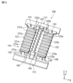
- FIG. 12 is a perspective view of the jig.
- the jig 100 has a first support portion 111, a second support portion 112, a first connecting portion 121, a second connecting portion 122, and a third connecting portion 123.
- the first support portion 111 and the second support portion 112 each extend in the X direction and are arranged parallel to each other in the Y direction.
- the first connecting portion 121, the second connecting portion 122, and the third connecting portion 123 each connect the first support portion 111 and the second support portion 112.
- the first connecting portion 121, the second connecting portion 122, and the third connecting portion 123 each extend in the Y direction and are arranged parallel to each other in the X direction.
- the first connecting portion 121 has a plurality of grooves 121a on its first main surface in the Z direction.
- the plurality of grooves 121a each extend in the X direction and are arranged parallel to each other in the Y direction.
- the first connecting portion 121 has a first positioning protrusion 131 and a second positioning protrusion 132 that protrude in the Z direction on its first main surface in the Z direction.
- the first positioning protrusion 131 is provided on the first support portion 111 side
- the second positioning protrusion 132 is provided on the second support portion 112 side.
- the second connecting portion 122 has a plurality of first groove portions 122a on a first side surface in the X direction.
- the plurality of first groove portions 122a each extend in the Z direction and are arranged parallel to each other in the Y direction.
- the second connecting portion 122 has a plurality of second groove portions 122b on a second side surface in the other X direction.
- the plurality of second groove portions 122b each extend in the Z direction and are arranged parallel to each other in the Y direction.
- the third connecting portion 123 has a plurality of grooves 123a on its first main surface in the Z direction.
- the plurality of grooves 123a each extend in the X direction and are arranged parallel to each other in the Y direction.
- the third connecting portion 123 has a third positioning protrusion 133 and a fourth positioning protrusion 134 that protrude in the Z direction on its first main surface in the Z direction.
- the third positioning protrusion 133 is provided on the first support portion 111 side
- the fourth positioning protrusion 134 is provided on the second support portion 112 side.
- the jig 100 has first to fourth holes 141 to 144 that penetrate in the Z direction.
- the first hole 141 is located on the opposite side of the first connecting portion 121 to the second connecting portion 122 (reverse X-direction side).
- the second hole 142 is located between the first connecting portion 121 and the second connecting portion 122.
- the third hole 143 is located between the second connecting portion 122 and the third connecting portion 123.
- the fourth hole 124 is located on the opposite side of the third connecting portion 121 to the second connecting portion 122 (forward X-direction side).
- Figure 13 is a bottom view showing the state in which the jig is used in the manufacturing method of the coil component.
- Figure 14 is a perspective view of Figure 13 with the core and base case omitted.
- the coil forming process includes connecting the ends of each straight pin member 411, 412, 421, 422 and each bent pin member 410, 420 with the ends of each bent pin member 410, 420 while fitting each straight pin member 411, 412, 421, 422 into grooves 121a, 122a, 122b, 123a of the jig 100.
- the straight pin members 411, 412 of the first coil 41 are fitted into the groove 121a of the first connecting portion 121.
- the bent pin member 410 of the first coil 41 is fitted into the first groove 122a of the second connecting portion 122.
- the straight pin members 421, 422 of the second coil 42 are fitted into the groove 123a of the third connecting portion 123.
- the bent pin member 420 of the second coil 42 is fitted into the second groove 122b of the second connecting portion 122.
- the straight pin members 411, 412, 421, 422 and the bent pin members 410, 420 can be connected while being positioned, improving the connection reliability of the straight pin members 411, 412, 421, 422 and the bent pin members 410, 420.
- the coil forming process includes connecting the ends of each straight pin member 411, 412, 421, 422 to the ends of each bent pin member 410, 420 while exposing the ends of each straight pin member 411, 412, 421, 422 and the ends of each bent pin member 410, 420 from the first to fourth hole portions 141 to 144 of the jig 100.
- connection points between the ends of the straight pin members 411, 412, 421, and 422 and the ends of the bent pin members 410 and 420 are exposed from the first to fourth hole portions 141 to 144. Then, for example, a welding tool is inserted through the first to fourth hole portions 141 to 144 to weld the above connection points.
- the electrode terminal connection process includes connecting the first to fourth electrode terminals 51 to 54 to the endmost straight pin members 411, 421 with the first to fourth positioning protrusions 131 to 134 of the jig 100 inserted into the slits 51a to 54a of the first to fourth electrode terminals 51 to 54.
- the first electrode terminal 51 is connected to the end straight pin member 411 with the first positioning protrusion 131 of the jig 100 inserted into the slit portion 51a of the first electrode terminal 51.
- the second electrode terminal 52 is connected to the end straight pin member 411 with the second positioning protrusion 132 of the jig 100 inserted into the slit portion 52a of the second electrode terminal 52.
- the third electrode terminal 53 is connected to the end straight pin member 421 with the third positioning protrusion 133 of the jig 100 inserted into the slit portion 53a of the third electrode terminal 53.
- the fourth electrode terminal 54 is connected to the end straight pin member 421 with the fourth positioning protrusion 134 of the jig 100 inserted into the slit portion 54a of the fourth electrode terminal 54.
- the first to fourth electrode terminals 51 to 54 can be connected to the end straight pin members 411, 421 while being positioned, improving the connection reliability between the end straight pin members 411, 421 and the first to fourth electrode terminals 51 to 54.
- the electrode terminal connection process includes connecting the first to fourth electrode terminals 51 to 54 to the endmost straight pin members 411, 421 while exposing the endmost straight pin members 411, 421 and the first to fourth electrode terminals 51 to 54 from the first to fourth hole portions 141 to 144 of the jig 100.
- connection points between the endmost straight pin member 411 and the first electrode terminal 51 are exposed from the first and second hole portions 141, 142, and the connection points between the endmost straight pin member 411 and the second electrode terminal 52 are exposed from the first and second hole portions 141, 142.
- connection points between the endmost straight pin member 421 and the third electrode terminal 53 are exposed from the third and fourth hole portions 143, 144, and the connection points between the endmost straight pin member 421 and the fourth electrode terminal 54 are exposed from the third and fourth hole portions 143, 144.
- a welding tool is inserted through the first to fourth hole portions 141-144 to weld the above-mentioned connection points.
- connection between the straight pin members 411, 412, 421, 422 and the bent pin members 410, 420, and the connection between the end straight pin members 411, 421 and the first to fourth electrode terminals 51 to 54 can be performed in a single process.
- the coil component at least comprises a core, a core cover portion, and a coil
- the most-end straight pin member faces a first surface of the first part of the core cover portion
- the first end of the most-end straight pin member contacts a protrusion on the first surface of the first part of the core cover portion
- the second end of the most-end straight pin member is spaced from the first surface and connected to the bent pin member.
- the core cover and mounting base are integrated, but they may be separate, or the core cover and mounting base may be separated. Also, the mounting base may be omitted and the electrode terminal may be attached to the bottom plate.
- the shape of the case and the shape of the core are not limited to the first embodiment and can be modified.
- the number of coils is not limited to the first embodiment and can be modified.
- the number of electrode terminals is not limited to the first embodiment and can be modified.
- the present disclosure includes the following aspects. ⁇ 1> An annular core; A core cover portion that covers at least a portion of the core; A coil is wound around the core and the core cover, the core has a first end surface and a second end surface opposed to each other in a central axis direction, the core cover portion has a first portion facing the first end surface, the first portion having a protrusion on a first surface opposite the first end surface, the coil includes a plurality of straight pin members and a plurality of bent pin members, the straight pin members and the bent pin members being alternately connected to form a spiral of the coil, and the plurality of straight pin members include an endmost straight pin member located at an end on at least one side of the axial direction of the coil, a coil component, wherein the endmost straight pin member faces the first surface of the first portion, a first end of the endmost straight pin member contacts the protrusion portion, and a second end of the endmost straight pin member is spaced from the first surface and connected to the bent pin member.
- ⁇ 2> further comprising an electrode terminal connected to the coil;
- ⁇ 3> The coil component according to ⁇ 2>, wherein the first end of the outermost straight pin member is connected to the electrode terminal.
- ⁇ 4> The coil component according to ⁇ 3>, wherein the protrusion overlaps the electrode terminal when viewed from a direction perpendicular to the first surface.
- ⁇ 5> The coil component according to ⁇ 2>, wherein the second end of the outermost straight pin member is connected to the electrode terminal.
- ⁇ 6> The coil component according to ⁇ 5>, wherein the protrusion is spaced apart from the electrode terminal when viewed in a direction perpendicular to the first surface.
- ⁇ 7> The coil component according to any one of ⁇ 2> to ⁇ 6>, wherein the endmost straight pin member and the electrode terminal are connected by welding. ⁇ 8> A mounting portion for mounting the electrode terminal is further provided.
- the step of arranging the straight pin members and the bent pin members includes: placing an endmost straight pin member located at an end on at least one side of the axial direction of the coil among the plurality of straight pin members against the first surface; and contacting a first end of the endmost straight pin member with a protrusion provided on the first surface;
- the method for manufacturing a coil component, in the process of forming the coil includes supporting the first end of
- ⁇ 10> The method for manufacturing a coil component according to ⁇ 9>, further comprising the step of connecting an electrode terminal to the endmost straight pin member and connecting the electrode terminal to the coil.
- step of forming the coil includes connecting ends of each of the straight pin members and each of the bent pin members while fitting each of the straight pin members and each of the bent pin members into a groove of a jig.
- ⁇ 12> The manufacturing method of a coil component described in ⁇ 11>, wherein the process of forming the coil includes connecting the ends of each of the straight pin members and the ends of each of the bent pin members while exposing the ends of each of the straight pin members and the ends of each of the bent pin members from holes in the jig.
- the step of forming the coil includes connecting an end of each of the straight pin members and an end of each of the bent pin members in a state in which the straight pin members and the bent pin members are fitted into grooves of a jig;
- the step of forming the coil includes connecting the ends of the straight pin members and the ends of the bent pin members while exposing the ends of the straight pin members and the ends of the bent pin members from holes in the jig;
Landscapes
- Engineering & Computer Science (AREA)
- Power Engineering (AREA)
- Manufacturing & Machinery (AREA)
- Microelectronics & Electronic Packaging (AREA)
- Coils Or Transformers For Communication (AREA)
Priority Applications (1)
| Application Number | Priority Date | Filing Date | Title |
|---|---|---|---|
| JP2025503624A JP7816631B2 (ja) | 2023-03-01 | 2024-01-12 | コイル部品およびその製造方法 |
Applications Claiming Priority (2)
| Application Number | Priority Date | Filing Date | Title |
|---|---|---|---|
| JP2023-031133 | 2023-03-01 | ||
| JP2023031133 | 2023-03-01 |
Publications (1)
| Publication Number | Publication Date |
|---|---|
| WO2024180924A1 true WO2024180924A1 (ja) | 2024-09-06 |
Family
ID=92590232
Family Applications (1)
| Application Number | Title | Priority Date | Filing Date |
|---|---|---|---|
| PCT/JP2024/000550 Ceased WO2024180924A1 (ja) | 2023-03-01 | 2024-01-12 | コイル部品およびその製造方法 |
Country Status (2)
| Country | Link |
|---|---|
| JP (1) | JP7816631B2 (https=) |
| WO (1) | WO2024180924A1 (https=) |
Citations (3)
| Publication number | Priority date | Publication date | Assignee | Title |
|---|---|---|---|---|
| JP2018182227A (ja) * | 2017-04-20 | 2018-11-15 | 株式会社村田製作所 | インダクタ及びインダクタの製造方法 |
| US20190035526A1 (en) * | 2017-07-28 | 2019-01-31 | Chicony Power Technology Co., Ltd. | Adapter, transformer, bobbin, and assembly method of transformer |
| JP2021048316A (ja) * | 2019-09-19 | 2021-03-25 | 株式会社村田製作所 | インダクタ部品およびインダクタ部品の製造方法 |
-
2024
- 2024-01-12 WO PCT/JP2024/000550 patent/WO2024180924A1/ja not_active Ceased
- 2024-01-12 JP JP2025503624A patent/JP7816631B2/ja active Active
Patent Citations (3)
| Publication number | Priority date | Publication date | Assignee | Title |
|---|---|---|---|---|
| JP2018182227A (ja) * | 2017-04-20 | 2018-11-15 | 株式会社村田製作所 | インダクタ及びインダクタの製造方法 |
| US20190035526A1 (en) * | 2017-07-28 | 2019-01-31 | Chicony Power Technology Co., Ltd. | Adapter, transformer, bobbin, and assembly method of transformer |
| JP2021048316A (ja) * | 2019-09-19 | 2021-03-25 | 株式会社村田製作所 | インダクタ部品およびインダクタ部品の製造方法 |
Also Published As
| Publication number | Publication date |
|---|---|
| JPWO2024180924A1 (https=) | 2024-09-06 |
| JP7816631B2 (ja) | 2026-02-18 |
Similar Documents
| Publication | Publication Date | Title |
|---|---|---|
| CN107533898B (zh) | 线圈部件及其制造方法 | |
| US11875930B2 (en) | Inductor component and method of manufacturing inductor component | |
| CN113674969A (zh) | 电感器部件 | |
| US11749449B2 (en) | Inductor component | |
| JP7816631B2 (ja) | コイル部品およびその製造方法 | |
| CN113284717B (zh) | 电感部件及其制造方法 | |
| JP7264144B2 (ja) | コイル部品 | |
| JP4983389B2 (ja) | コイル部品 | |
| CN113410023B (zh) | 电感部件 | |
| JP7758245B2 (ja) | コイル部品 | |
| JP2021048319A (ja) | インダクタ部品およびインダクタ部品の製造方法 | |
| CN113284697B (zh) | 电感器部件及其制造方法 | |
| CN113284698B (zh) | 电感器部件及其制造方法 | |
| CN113496811B (zh) | 电感器部件及其制造方法 | |
| JP7635882B2 (ja) | コイル部品およびコイル部品の製造方法 | |
| JP7715296B2 (ja) | インダクタ部品およびその製造方法 | |
| JP4702601B2 (ja) | コイル部品 | |
| JP3255621B2 (ja) | 表面実装チョークコイル | |
| JPH11340054A (ja) | チョークコイル | |
| WO2023008013A1 (ja) | インダクタ部品 | |
| WO2023176682A1 (ja) | インダクタ部品 | |
| JP2025080466A (ja) | コイル装置 | |
| JP2026006598A (ja) | コイル装置 | |
| JP2023002288A (ja) | コイル装置 |
Legal Events
| Date | Code | Title | Description |
|---|---|---|---|
| 121 | Ep: the epo has been informed by wipo that ep was designated in this application |
Ref document number: 24763409 Country of ref document: EP Kind code of ref document: A1 |
|
| WWE | Wipo information: entry into national phase |
Ref document number: 2025503624 Country of ref document: JP |
|
| NENP | Non-entry into the national phase |
Ref country code: DE |
|
| 122 | Ep: pct application non-entry in european phase |
Ref document number: 24763409 Country of ref document: EP Kind code of ref document: A1 |