WO2024176938A1 - 光学系および撮像装置 - Google Patents
光学系および撮像装置 Download PDFInfo
- Publication number
- WO2024176938A1 WO2024176938A1 PCT/JP2024/005232 JP2024005232W WO2024176938A1 WO 2024176938 A1 WO2024176938 A1 WO 2024176938A1 JP 2024005232 W JP2024005232 W JP 2024005232W WO 2024176938 A1 WO2024176938 A1 WO 2024176938A1
- Authority
- WO
- WIPO (PCT)
- Prior art keywords
- optical system
- transmissive
- lens
- image
- reflective surface
- Prior art date
- Legal status (The legal status is an assumption and is not a legal conclusion. Google has not performed a legal analysis and makes no representation as to the accuracy of the status listed.)
- Ceased
Links
Images


Classifications
-
- G—PHYSICS
- G02—OPTICS
- G02B—OPTICAL ELEMENTS, SYSTEMS OR APPARATUS
- G02B27/00—Optical systems or apparatus not provided for by any of the groups G02B1/00 - G02B26/00, G02B30/00
- G02B27/28—Optical systems or apparatus not provided for by any of the groups G02B1/00 - G02B26/00, G02B30/00 for polarising
- G02B27/286—Optical systems or apparatus not provided for by any of the groups G02B1/00 - G02B26/00, G02B30/00 for polarising for controlling or changing the state of polarisation, e.g. transforming one polarisation state into another
-
- G—PHYSICS
- G02—OPTICS
- G02B—OPTICAL ELEMENTS, SYSTEMS OR APPARATUS
- G02B13/00—Optical objectives specially designed for the purposes specified below
- G02B13/18—Optical objectives specially designed for the purposes specified below with lenses having one or more non-spherical faces, e.g. for reducing geometrical aberration
-
- G—PHYSICS
- G02—OPTICS
- G02B—OPTICAL ELEMENTS, SYSTEMS OR APPARATUS
- G02B17/00—Systems with reflecting surfaces, with or without refracting elements
- G02B17/08—Catadioptric systems
-
- G—PHYSICS
- G02—OPTICS
- G02B—OPTICAL ELEMENTS, SYSTEMS OR APPARATUS
- G02B17/00—Systems with reflecting surfaces, with or without refracting elements
- G02B17/08—Catadioptric systems
- G02B17/0804—Catadioptric systems using two curved mirrors
- G02B17/0808—Catadioptric systems using two curved mirrors on-axis systems with at least one of the mirrors having a central aperture
-
- G—PHYSICS
- G02—OPTICS
- G02B—OPTICAL ELEMENTS, SYSTEMS OR APPARATUS
- G02B17/00—Systems with reflecting surfaces, with or without refracting elements
- G02B17/08—Catadioptric systems
- G02B17/0856—Catadioptric systems comprising a refractive element with a reflective surface, the reflection taking place inside the element, e.g. Mangin mirrors
- G02B17/086—Catadioptric systems comprising a refractive element with a reflective surface, the reflection taking place inside the element, e.g. Mangin mirrors wherein the system is made of a single block of optical material, e.g. solid catadioptric systems
-
- G—PHYSICS
- G02—OPTICS
- G02B—OPTICAL ELEMENTS, SYSTEMS OR APPARATUS
- G02B5/00—Optical elements other than lenses
- G02B5/30—Polarising elements
Definitions
- the present invention relates to an optical system.
- optical systems that have a short optical length while maintaining good optical performance
- optical systems that have a short optical length while maintaining good optical performance
- examples of optical systems that have a short optical length while maintaining good optical performance include the periscope optical system disclosed in Patent Document 1 and the catadioptric optical system disclosed in Patent Document 2.
- the periscope optical system disclosed in Patent Document 1 is difficult to miniaturize in the direction perpendicular to the optical axis. Also, in the catadioptric optical system disclosed in Patent Document 2, it is difficult to make the light receiving element large relative to the transparent hole in the primary mirror, making it difficult to obtain high optical performance compared to the size of the optical system.
- the present invention provides an optical system that is compact and has high optical performance.
- An optical system has a first transmissive-reflective surface, a quarter-wave plate, and a second transmissive-reflective surface arranged in this order from the object side to the image side, the optical system being a primary imaging system, in which light from the object side passes through the first transmissive-reflective surface and the quarter-wave plate in this order, is reflected by the second transmissive-reflective surface towards the object side, passes through the quarter-wave plate, is reflected by the first transmissive-reflective surface towards the image side, passes through the quarter-wave plate and the second transmissive-reflective surface in this order towards the image side, and when the distance on the optical axis from the first transmissive-reflective surface to the image surface is zm1 and the focal length of the optical system is f, then: 0.10 ⁇ zm1/f ⁇ 0.68
- the present invention is characterized in that the following conditional expression is satisfied:
- the present invention provides an optical system that is compact and has high optical performance.
- FIG. 2 is a schematic diagram showing an optical path of an optical system.
- FIG. 2 is a schematic diagram showing an optical path of an optical system.
- FIG. 2 is a cross-sectional view of an optical system according to the first embodiment.
- 4A to 4C are aberration diagrams of the optical system in Example 1.
- FIG. 11 is a cross-sectional view of an optical system according to a second embodiment. 11A to 11C are aberration diagrams of the optical system in Example 2.
- FIG. 13 is a cross-sectional view of an optical system in Example 5.
- 13A to 13C are aberration diagrams of the optical system in Example 5.
- FIG. 13 is a cross-sectional view of an optical system in Example 6.
- 13A to 13C are aberration diagrams of the optical system in Example 6.
- FIG. 13 is a cross-sectional view of an optical system in Example 7.
- 13A to 13C are aberration diagrams of the optical system in Example 7.
- FIG. 13 is a cross-sectional view of an optical system in Example 8.
- 13A to 13C are aberration diagrams of the optical system in Example 8.
- FIG. 13 is a cross-sectional view of an optical system in Example 9.
- 13A to 13C are aberration diagrams of the optical system in Example 9.
- FIG. 23 is a cross-sectional view of an optical system in Example 10.
- FIG. 23 is a cross-sectional view of an optical system in Example 11.
- 13A to 13C are aberration diagrams of the optical system in Example 11.
- FIG. 23 is a cross-sectional view of an optical system in Example 12.
- 13A to 13C are aberration diagrams of the optical system in Example 12.
- the imaging optical system in each embodiment is an optical system that forms an image of an object on an image plane, and is an optical system for acquiring the image using a solid-state image sensor or photosensitive film arranged on the image plane.
- the imaging optical system of each embodiment has a first transmissive-reflective surface, a quarter-wave plate (QWP), and a second transmissive-reflective surface, arranged in this order from the object side to the image side.
- Light from the object side passes through the first transmissive-reflective surface and the QWP in that order, and is reflected by the second transmissive-reflective surface.
- the light then passes through the QWP and is reflected by the first transmissive-reflective surface, before passing through the QWP and the second transmissive-reflective surface, and heading toward an imaging unit such as a solid-state image sensor or photosensitive film.
- the first transmissive-reflective surface and the second transmissive-reflective surface may absorb light.
- lenses may be formed or bonded to both or one side of each transmissive/reflective surface.
- a QWP for example, a polymer film having birefringence or a liquid crystal alignment layer can be used. Also, a laminate of such polymer films or liquid crystal alignment layers can be used as a QWP. By appropriately laminating these, a phase difference close to a quarter of the wavelength can be obtained over a wide wavelength range.
- an inorganic wave plate from Dexerials Corporation can also be used as a QWP.
- the QWP can be arranged, for example, by bonding it to the first transmissive-reflective surface or the second transmissive-reflective surface.
- the QWP can also be arranged separately from these transmissive-reflective surfaces.
- the film can be inserted directly into the optical path, or a film bonded to a glass plate can be inserted into the optical path.
- a lens can also be formed or bonded to one or both sides of the QWP.
- a lens can be molded on one or both sides of the inorganic waveplate using wafer-level optics technology with the inorganic waveplate as a substrate.
- the imaging optical system of each embodiment satisfies the following conditional expression (1).
- the distance on the optical axis from the first transmissive-reflective surface to the image plane is zm1
- the focal length of the imaging optical system is f.
- Focal length is defined as the ratio of the height of an incident ray of light parallel to the optical axis from infinity in the paraxial region to the angle of emergence of that ray when it leaves the optical system, as described in Matsui Yoshiya's "Introduction to Imaging Optical Systems: Fundamentals of Handling Optical Systems," Japan Optomechatronics Association, 1988, pp. 45-48.
- the sign of the focal length of an optical system that forms an intermediate image is negative.
- the imaging optical system If it is only necessary to balance the performance and compactness of the imaging optical system alone, it is sufficient to make the entire imaging optical system as small as possible. Aberrations other than distortion aberration also become smaller in proportion to the size, making it possible to realize an imaging optical system that is small and has high optical performance.
- the imaging surface also becomes small, and high optical performance cannot be obtained as an entire imaging system. This is because, although solid-state imaging elements and photosensitive film are arranged on the imaging surface, there are technical limits to the pixel density of solid-state imaging elements and the resolution per area of photosensitive film. In addition, the diffraction limit dictates the minimum pixel size that is meaningful. For this reason, in order to realize high image quality as an imaging system, it is preferable for the imaging optical system to be compatible with a large image circle while having low aberration.
- the imaging optical system of each embodiment satisfies the following conditional expression (2).
- the total length of the imaging optical system excluding the diaphragm is La
- the image circle radius is h
- the F-number of the imaging optical system is Fno.
- the total length of the imaging optical system excluding the aperture is the total length of the imaging optical system excluding the aperture in the case where the aperture with a fixed diameter that acts as a light blocking mask is disposed closest to the object.
- the total length of the optical system In other imaging optical systems, it is the total length of the imaging optical system.
- the total length of the imaging optical system is the distance on the optical axis from the optical surface closest to the object to the image plane. In other words, the total length of an imaging optical system excluding the aperture can be said to be the distance on the optical axis from the lens surface closest to the object to the image plane.
- conditional expression (2) cannot be exceeded. If the upper limit of conditional expression (2) is exceeded, the angle of incidence of off-axis light on the image plane becomes large. This is undesirable because it reduces the exit pupil for the off-axis region, reducing resolution due to diffraction, or lengthening the overall length. Furthermore, if the angle of incidence on the image plane becomes large, it is undesirable because it makes it easier for optical crosstalk to occur in surrounding pixels when a solid-state imaging element is used as the imaging element.
- the imaging optical system of each embodiment preferably satisfies the following conditional expression (3).
- the distance on the optical axis from the aperture stop to the image plane is zp.
- the aperture diaphragm is a diaphragm whose light transmitting area can be changed, such as an iris diaphragm or a Waterhouse diaphragm.
- the aperture diaphragm does not necessarily need to be physically blocked, for example, It may be of a form in which the color density distribution is controlled by applying a voltage using an electrochromic element.
- the aperture stop is likely to cause vignetting of the upper line, which is undesirable. If the imaging optical system does not have an aperture stop, the outer diameter of the lens is likely to cause vignetting of the upper line, which is undesirable. If above the upper limit of conditional expression (3), if the imaging optical system has an aperture stop, the aperture stop is likely to cause vignetting of the lower line, which is undesirable. If the imaging optical system does not have an aperture stop, the outer diameter of the lens is likely to cause vignetting of the lower line, which is undesirable. It is possible to reduce vignetting by increasing the diameter of the imaging optical system, but taking such measures will increase the size of the entire imaging optical system.
- Such vignetting of light rays has disadvantages such as a decrease in peripheral light amount and a reduction in the image circle.
- the area of the exit pupil is reduced, the frequency characteristics in the meridional direction are deteriorated due to the diffraction phenomenon, resulting in a decrease in image quality.
- the imaging optical system of each embodiment preferably satisfies the following conditional expression (4).
- the diameter of the first transmissive-reflective surface is ⁇ m1
- the diameter of the second transmissive-reflective surface is ⁇ m2.
- diameter refers to the diameter of the effective area of the transmissive-reflective surface (area through which effective light rays that contribute to imaging pass).
- the imaging optical system of each embodiment satisfies the following conditional expression (5).
- the imaging optical system of each embodiment preferably satisfies the following conditional expression (6).
- the distance on the optical axis from the second transmissive-reflective surface to the image plane is zm2.
- the imaging optical system of each embodiment preferably satisfies the following conditional expression (7).
- the absolute value of the refractive power of the lens including the second transmissive-reflective surface is ⁇ m1L.
- the imaging optical system of each embodiment preferably satisfies the following conditional expression (8).
- the average value of the absolute values of the refractive power of each of the multiple lenses included in the imaging optical system is A ⁇ r
- the average value of the absolute values of the power (refractive power) of the first transmissive-reflective surface and the second transmissive-reflective surface is A ⁇ m.
- the power (reflective power) of a reflective surface corresponds to the reciprocal of the paraxial focal length of the reflective surface, and for example, if the surface is spherical, it is the reciprocal of the paraxial radius of curvature multiplied by -2.
- the reflective component of the power is the reciprocal of the paraxial radius of curvature multiplied by -2 (for example, if the shape is spherical), and this value is used when calculating A ⁇ r.
- conditional expression (8) cannot be exceeded. If the upper limit of conditional expression (8) is exceeded, the refractive power will dominate over the reflective power in the entire imaging optical system. Due to the nature of the reflecting surface, chromatic aberration will not occur during reflection. On the other hand, chromatic aberration will occur during refraction of the lens. For this reason, if the refractive power in the entire system becomes large, axial chromatic aberration and lateral chromatic aberration will appear, which is undesirable as it will impair image quality.
- the imaging optical system can be an optical system capable of imaging, for example, from the visible range to the infrared range, or an optical system capable of imaging a wide infrared wavelength range.
- the imaging optical system of each embodiment satisfies the following condition (9).
- the imaging optical system of each embodiment satisfies the following conditional expression (10).
- one of the first transmissive-reflective surface and the second transmissive-reflective surface, or both of the first transmissive-reflective surface and the second transmissive-reflective surface are flat. This is preferable because it makes it easier to manufacture the imaging optical system.
- conditional expressions (1) to (10) are within the ranges of the following conditional expressions (1a) to (10a).
- the first transmission-reflection surface or the second transmission-reflection surface is a surface that separates incident light into reflected light and transmitted light according to the polarization state.
- a polarization selective transmission reflection element as either the first transmission reflection surface or the second transmission reflection surface.
- a polarization selective transmission reflection element examples include "WGF” manufactured by 3M Company, "IQPE” manufactured by MOXTEK, and “ProFlux” manufactured by MOXTEK.
- WGF WGF
- IQPE IQPE
- MOXTEK MOXTEK
- ProFlux manufactured by MOXTEK.
- a half mirror can be used. When used, the amount of randomly polarized light incident from the object side is reduced to 12.5% or less by the time it reaches the image plane.
- Cholesteric liquid crystal or holographic optical elements may also be used as the transmissive and reflective surface.
- the polarization selective transmissive reflecting element may be an optical element that is created by forming a grid on the lens reflecting surface during lens molding and then evaporating, printing, or lithographically depositing a metal or dielectric material on the grid.
- the shape of the effective area of each of the multiple lens surfaces included in the imaging optical system of each embodiment is rotationally symmetric with respect to the optical axis.
- the imaging optical system is rotationally symmetric in the effective area of each optical surface, the positioning method of each optical element can be simplified.
- the imaging optical system is rotationally symmetric, including the outer shape of each optical element, the ease of manufacture can be further improved.
- the imaging optical system of each embodiment for example, by adopting the following configuration, it is possible to suppress a decrease in the amount of light in the normal imaging optical path while reducing ghost light (unwanted light leakage) from the optical path that passes through the transmitting and reflecting surface without even once.
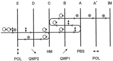
- the imaging optical system of this configuration has two transmissive and reflective surfaces.
- the transmissive and reflective surface disposed on the object side of the imaging optical system of this configuration is configured by disposing a polarization selective transmissive and reflective element (PBS): A.
- the transmissive and reflective surface disposed on the image surface side of the imaging optical system of this configuration is configured by disposing a half mirror (HM): C.
- HM half mirror
- QWP1 B is disposed between the polarization selective transmissive and reflective element PBS and the half mirror HM.
- QWP2 D
- a linear polarizer (POL): E are disposed between the half mirror HM and the imaging surface IM, in that order from the object side to the image side.
- the polarization selective transmission reflection element A is an element configured to reflect linearly polarized light polarized in the same direction as when it was transmitted through the linear polarizer E, and to transmit linearly polarized light perpendicular to that.
- the polarization selective transmission reflection element A is, for example, a wire grid polarizer or a reflective polarizer having a laminated retardation film configuration.
- the wire grid forming surface or retardation film surface of the polarization selective transmission reflection element A functions as the transmission reflection surface.
- the wire grid polarizer does not necessarily have to be one in which metal wires are aligned, but it may have thin metal or dielectric layers at specified intervals and function as a polarization selective transmission reflection element.
- an element in which metal or dielectric layers are aligned by vapor deposition can be used.
- first quarter-wave plate B and the second quarter-wave plate D are arranged with their slow axes tilted at 45° with respect to the polarization transmission axis of the linear polarizer E.
- first quarter-wave plate B and the second quarter-wave plate D are arranged with their slow axes tilted at 90°.
- the half mirror C is a half mirror formed, for example, by a dielectric multilayer film or metal deposition, and the mirror surface of the half mirror C functions as a transmissive/reflective surface.
- the linear polarizer E is, for example, an absorptive linear polarizer.
- Light entering the imaging optical system from the object side becomes linearly polarized by the polarization-selective transmissive reflector A, becomes circularly polarized by the first quarter-wave plate B, and enters the half mirror C. A portion of the light that reaches the half mirror C is reflected and becomes circularly polarized in the reverse direction, returning to the first quarter-wave plate B.
- the counter-circularly polarized light that returned to the first quarter-wave plate B returns to the polarization selective transmission reflector A as linearly polarized light polarized in a direction perpendicular to the direction when the light first passed through the polarization selective transmission reflector A.
- the light that returned to the polarization selective transmission reflector A is reflected by the polarization selective transmission reflector A. Due to the polarization selectivity of the polarization selective transmission reflector A, linearly polarized light polarized in a direction perpendicular to the direction when the light first passed through the polarization selective transmission reflector A is reflected.
- part of the light that reaches the half mirror C is transmitted and becomes linearly polarized light polarized in the same direction as when it passed through the polarization-selective transflective element A by the second quarter-wave plate D, and is incident on the linear polarizer E and absorbed by the linear polarizer E.
- the light reflected by the polarization-selective transflector A is circularly polarized by the first quarter-wave plate B and enters the half mirror C. A portion of the light that reaches the half mirror C is transmitted and enters the second quarter-wave plate D.
- the second quarter-wave plate D causes the incident light to become linearly polarized light that is oriented parallel to the linearly polarized light reflected by the polarization-selective transflector A.
- the light that passes through the second quarter-wave plate D enters the linear polarizer E.
- the polarization of the light and the transmission axis of the linear polarizer E are consistent, so most of the light is transmitted and directed to the imaging plane IM.
- solid-state imaging elements and CCDs that can be used as the imaging surface IM generally have high surface reflectance.
- the light reflected by the imaging surface IM passes through the linear polarizer E again and is converted into circularly polarized light by the second quarter-wave plate D.
- the light that leaves the second quarter-wave plate D is then reflected by the half mirror C to become circularly polarized light in the opposite direction, and passes through the second quarter-wave plate D again.
- the circularly polarized light is converted by the second quarter-wave plate D into linearly polarized light in a perpendicular direction to the light that was just before passing through the linear polarizer E.
- a quarter-wave plate may be placed between the polarization-selective transflective element A and the object.
- the quarter-wave plate is placed so that the fast or slow axis of the quarter-wave plate forms an angle of 45° with the transmission axis of the polarization-selective transflective element A.
- a depolarizing element may be placed instead of the quarter-wave plate. For example, Toyobo Co., Ltd.'s "Cosmoshine SRF" can be used as the depolarizing element.
- the imaging optical system of this configuration has two transmissive and reflective surfaces.
- the transmissive and reflective surface arranged on the object side of the imaging optical system of this configuration is configured by arranging a half mirror (HM): C.
- the transmissive and reflective surface arranged on the imaging surface side of the imaging optical system of this configuration is configured by arranging a polarization selective transmissive and reflective element (PBS): A.
- a first quarter-wave plate (QWP1): B is arranged between the polarization selective transmissive and reflective element PBS and the half mirror HM.
- a linear polarizer (POL): E and a second quarter-wave plate (QWP2): D are arranged between the half mirror HM and the object surface, in order from the object side to the image side.
- each polarizing element and the preferred arrangement of the optical axis orientation are the same as in Polarized Light Configuration 1.
- the light that reaches and is reflected by the half mirror C is circularly polarized in the opposite direction to when it was incident. This light is then polarized by the second quarter-wave plate D in a direction perpendicular to when it passed through the linear polarizer E, and is then incident on and absorbed by the linear polarizer E.
- the light that passes through half mirror C becomes linearly polarized light by first quarter-wave plate B, polarized in the same direction as the light immediately after passing through linear polarizer E.
- This linearly polarized light is reflected by polarization-selective transmission-reflection element A and returns to first quarter-wave plate B.
- the light is then converted into circularly polarized light by first quarter-wave plate B, and part of it is reflected by half mirror C.
- the light reflected by half mirror C enters first quarter-wave plate B again, where it is converted into linearly polarized light whose polarization direction is orthogonal to when it was reflected by polarization-selective transmission-reflection element A.
- This linearly polarized light passes through polarization-selective transmission-reflection element A and is guided to the imaging plane IM.
- a linear polarizer A' may be placed between the polarization-selective transflective element A and the imaging surface IM.
- the transmission axes of the linear polarizer A' and the polarization-selective transflective element A are aligned. In this way, it is possible to absorb light that is reflected by the imaging surface IM, then reflected by the polarization-selective transflective element A, and then again enters the imaging surface IM, causing ghosts and flares.
- a quarter-wave plate may be placed between the linear polarizer E and the object.
- the quarter-wave plate is placed so that the fast axis or slow axis of the quarter-wave plate forms an angle of 45° with the transmission axis of the linear polarizer E.
- a depolarizing element may be placed instead of the quarter-wave plate.
- Toyobo Co., Ltd.'s "Cosmoshine SRF" can be used as the depolarizing element.
- the lens may be made of a polymer material or a glass material.
- the lens disposed between the first transmissive-reflective surface and the second transmissive-reflective surface has low birefringence.
- the quarter-wave plate may be, for example, a polymer film such as "WA-140T” manufactured by Nippon Kayaku Co., Ltd., "CP3” manufactured by ColorLink Japan Co., Ltd., or "ZEONORFILM” manufactured by Zeon Corporation.
- products manufactured by Astropribor under the product names "APAW”, “APSAW-5”, and “APSAW-7” and products manufactured by Thorlabs under the product names “Super Achromatic Waveplate” (model numbers: SAQWP05M-700, SAQWP05M-1700, etc.) and “Achromatic Waveplate” (model numbers: AQWP05M-600, AQWP05M-580, AQWP10M-580, etc.) may be used.
- a quarter-wave plate placed between two transmissive and reflective surfaces does not have sufficient characteristics (i.e., it deviates from the ideal characteristics of providing only a phase delay of exactly a quarter wavelength, provides a phase difference that is too large or too small, or has a component that acts as a depolarizer or optical rotator), ghost and flare increase. Specifically, for example, if the phase difference deviates from a quarter wavelength, the light that is reflected twice by each of the two transmissive and reflective surfaces reaches the image plane as ghost and flare.
- the intensity of the ghost light is expressed as ⁇ (1-cos(2 ⁇ )) ⁇ 2 ⁇ x (1+cos(2 ⁇ )) x a/64 (a is a constant that summarizes the absorption, reflection, and other factors of each lens in the optical system). Note that the calculations here assume ideal characteristics for the polarizing plate (i.e., it absorbs all polarized light in the absorption axis direction and transmits all polarized light in the transmission axis direction). We will tentatively call this ghost light a five-path ghost.
- the amount of light in the normal light path (preferably the light path through which the light ray passes) explained in the above configuration is (1-cos(2 ⁇ )) ⁇ 2) ⁇ a/16, so the ratio of the amount of light in the normal light to the five-pass ghost light path is 4/(1+cos(2 ⁇ )).
- the above Mueller matrix is a matrix that is used to convert a linearly polarized light into a quarter-wave plate perpendicularly. This is the expression when viewed from the incident side, and the angle between the axis corresponding to the fast axis (or slow axis) and the incident polarized light is 45°. It is a region where the light receiving part, such as an element or a photosensitive film, has sufficient sensitivity and where reflection and absorption in the optical system are sufficiently small.
- the spectrum of the incident light is also taken into consideration. Specifically, the product of the sensitivity of the light receiving part, the efficiency of the optical system, and the spectrum of the incident light is in a range of 10% or more or 20% or more of the peak. The wavelength region.
- conditional expressions (11a) and (12a) are more preferable to change conditional expressions (11b), (12b), (11c), (12c), (11d), and (12d), respectively.
- a quarter-wave plate that satisfies such conditions over the entire visible range (for example, from 420 nm to 680 nm)
- a half-wave plate with each optical axis tilted by about 15° with respect to the incident polarization direction and a half-wave plate with each optical axis tilted by about 75° with respect to the incident polarization direction are used.
- HQ type quarter wave plates are stacked on top of each other, or two half wave plates and one quarter wave plate are combined at a given angle (typically, for example, Pancharatnam type quarter-wave plates are available, with their optical axes at 6.5°, 34.57°, and 101.13° to the incident polarization direction. These are suitable for use in the present invention. It is.
- the other quarter-wave plate i.e., D in Figures 1 and 2
- characteristics similar to those of the above-mentioned wave plate For light that is not reflected even once by the two transmissive and reflective surfaces, these two quarter-wave plates each act once to cancel out the effects of the other, preventing the light from reaching the image plane. For this reason, it is preferable for the characteristics of the two quarter-wave plates to be as close to identical as possible, since this will result in a state where the cancellation of the characteristics is nearly complete.
- the optical system of this embodiment is an optical system that does not form an intermediate image (does not form an intermediate image), i.e., a primary imaging system.
- a primary imaging system an image plane is formed at the position where the incident light is first focused. In this way, the overall length of the optical system can be kept short.
- a primary imaging system there is no need to strengthen the power of each lens compared to an optical system that forms an intermediate image (does form an intermediate image), i.e., a secondary imaging system, so aberration correction is easier than with a secondary imaging system.
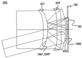
- FIG. 3 is a cross-sectional view of the imaging optical system 100.
- the imaging optical system 100 is composed of a first lens 101 having a first transmissive reflecting surface HM1, a second lens 102, a third lens 103 having a second transmissive reflecting surface HM2, and a sensor protective glass GB, arranged in this order from the object side to the image side.
- the first lens 101 has a quarter-wave plate QWP on the image side of the first transmissive reflecting surface HM1.
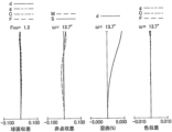
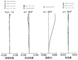
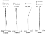
- FIG. 4 shows an aberration diagram of the imaging optical system 100 when focused at infinity, and shows the aberration diagram of the imaging optical system 100 at wavelengths of the d-line, F-line, C-line, and g-line.
- focusing is performed by moving the first lens 101, the second lens 102, and the third lens 103 together in the optical axis direction.
- FIG. 5 is a cross-sectional view of the imaging optical system 200.
- the imaging optical system 200 is composed of a first lens 201 having a first transmissive reflecting surface HM1, a second lens 202, a third lens 203 having a second transmissive reflecting surface HM2, and a sensor protective glass GB, arranged in this order from the object side to the image side.
- the first lens 201 has a quarter-wave plate QWP on the image side of the first transmissive reflecting surface HM1.
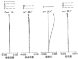
- FIG. 6 shows an aberration diagram of the imaging optical system 200 when focused at infinity, and shows the aberration diagram of the imaging optical system 200 at wavelengths of the d-line, F-line, C-line, and g-line.
- focusing is performed by moving the first lens 201, the second lens 202, and the third lens 203 together in the optical axis direction.
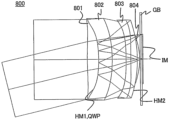
- FIG. 7 is a cross-sectional view of the imaging optical system 300.
- the imaging optical system 300 is composed of, arranged in order from the object side to the image side, a first lens 301, an aperture stop SP, a second lens 302 having a first transmissive reflecting surface HM1, a third lens 303, a fourth lens 304 having a second transmissive reflecting surface HM2, and a sensor protective glass GB.
- the second lens 302 has a quarter-wave plate QWP on the image side of the first transmissive reflecting surface HM1.
- Figure 8 shows aberration diagrams when the imaging optical system 300 is focused at infinity, for the wavelengths of the d-line, F-line, C-line, and g-line.
- focusing is performed by moving the first lens 301, the second lens 302, the third lens 303, and the fourth lens 304 as a whole in the optical axis direction.
- FIG. 9 is a cross-sectional view of the imaging optical system 400.
- the imaging optical system 400 is composed of, arranged in order from the object side to the image side, a first lens 401, an aperture stop SP, a second lens 402 having a first transmissive reflecting surface HM1, a third lens 403, a fourth lens 404 having a second transmissive reflecting surface HM2, and a sensor protective glass GB.
- the second lens 402 has a quarter-wave plate QWP on the image side of the first transmissive reflecting surface HM1.
- FIG. 10 shows aberration diagrams for the imaging optical system 400 when focused at infinity, for the wavelengths of the d-line, F-line, C-line, and g-line.
- focusing is performed by moving the first lens 401, the second lens 402, the third lens 403, and the fourth lens 404 as a whole in the optical axis direction.
- FIG. 11 is a cross-sectional view of the imaging optical system 500.
- the imaging optical system 500 is composed of, arranged in order from the object side to the image side, a first lens 501, an aperture stop SP, a second lens 502 having a first transmissive reflecting surface HM1, a third lens 503, a fourth lens 504 having a second transmissive reflecting surface HM2, and a sensor protective glass GB.
- the second lens 502 has a quarter-wave plate QWP on the image side of the first transmissive reflecting surface HM1.
- FIG. 12 shows aberration diagrams for the imaging optical system 500 when focused at infinity, for the wavelengths of the d-line, F-line, C-line, and g-line.
- focusing is performed by moving the first lens 501, the second lens 502, the third lens 503, and the fourth lens 504 as a whole in the optical axis direction.
- FIG. 13 is a cross-sectional view of the imaging optical system 600.
- the imaging optical system 600 is composed of, arranged in order from the object side to the image side, a first lens 601, an aperture stop SP, a second lens 602, a third lens 603 having a first transmissive reflecting surface HM1, a fourth lens 604, a fifth lens 605 having a second transmissive reflecting surface HM2, and a sensor protective glass GB.
- the third lens 603 also has a quarter-wave plate QWP on the image side of the first transmissive reflecting surface HM1.
- FIG. 14 shows the aberration diagrams for the imaging optical system 600 when focused at infinity, and shows the aberration diagrams for wavelengths of the d-line, F-line, C-line, and g-line.
- focusing is performed by moving the first lens 601, the second lens 602, the third lens 603, the fourth lens 604, and the fifth lens 605 as a whole in the optical axis direction.
- FIG. 15 is a cross-sectional view of the imaging optical system 700.
- the imaging optical system 700 is composed of a first lens 701 having a first transmissive reflecting surface HM1, a second lens 702, a third lens 703 having a second transmissive reflecting surface HM2, and a sensor protective glass GB, arranged in this order from the object side to the image side.
- the first lens 701 has a quarter-wave plate QWP on the image side of the first transmissive reflecting surface HM1.
- FIG. 16 shows an aberration diagram of the imaging optical system 700 when focused at infinity, and shows the wavelength aberration diagrams for the d-line, F-line, C-line, and g-line.
- focusing is performed by moving the first lens 701, the second lens 702, and the third lens 703 together in the optical axis direction. Focusing may also be performed by moving the third lens 703.
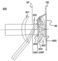
- FIG. 17 is a cross-sectional view of the imaging optical system 800.
- the imaging optical system 800 is composed of a cemented lens in which a first lens 801 having a first transmission-reflection surface HM1 and a second lens 802 are integrated in this order, a third lens 803, a fourth lens 804 having a second transmission-reflection surface HM2, and a sensor protective glass GB, which are arranged in this order from the object side to the image side.
- the first lens 801 has a quarter-wave plate QWP on the image side of the first transmission-reflection surface HM1.
- FIG. 18 shows an aberration diagram of the imaging optical system 800 when focused at infinity, and shows the wavelength aberration diagrams for the d-line, F-line, C-line, and g-line.
- focusing is performed by moving the first lens 801, the second lens 802, the third lens 803, and the fourth lens 804 as a whole in the optical axis direction.
- FIG. 19 is a cross-sectional view of the imaging optical system 900.
- the imaging optical system 900 is composed of, arranged in order from the object side to the image side, a first lens 901, a second lens 902 having a first transmission-reflection surface HM1, a third lens 903, an aperture stop SP, and a fourth lens 904 having a second transmission-reflection surface HM2.
- the second lens 902 has a quarter-wave plate QWP on the image side of the first transmission-reflection surface HM1.
- Figure 20 shows an aberration diagram for the imaging optical system 900 when focused at infinity, and shows the wavelength aberration diagrams for the d-line, F-line, C-line, and g-line.
- focusing is performed by moving the first lens 901, the second lens 902, the third lens 903, and the fourth lens 904 as a whole in the optical axis direction.
- FIG. 21 is a cross-sectional view of the imaging optical system 1000.
- the imaging optical system 1000 is composed of a first lens 1001 having a first transmissive reflecting surface HM1, an aperture stop SP, a second lens 1002, and a third lens 1003 having a second transmissive reflecting surface HM2, arranged in this order from the object side to the image side.
- the first lens 1001 has a quarter-wave plate QWP on the image side of the first transmissive reflecting surface HM1.
- Figure 22 shows the aberration diagram when focused at infinity, and shows the wavelength aberration diagrams for the d-line, F-line, C-line, and g-line.
- focusing is performed by moving the first lens 1001, the second lens 1002, and the third lens 1003 together in the optical axis direction.
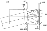
- FIG. 23 is a cross-sectional view of the imaging optical system 1100.
- the imaging optical system 1100 is composed of a first lens 1101 having a first transmissive reflective surface HM1, an aperture stop SP, a second lens 1102 having a second transmissive reflective surface HM2, and a sensor protective glass GB, arranged in this order from the object side to the image side.
- the first lens 1101 has a quarter-wave plate QWP on the image side of the first transmissive reflective surface HM1.
- Figure 24 shows aberration diagrams when the imaging optical system 1100 is focused at infinity, and shows aberration diagrams for wavelengths of the d-line, F-line, C-line, and g-line.
- focusing is performed by moving the first lens 1101 and the second lens 1102 together in the optical axis direction.
- FIG. 235 is a cross-sectional view of the imaging optical system 1200.
- the imaging optical system 1200 is composed of, arranged in order from the object side to the image side, a first lens 1201, a second lens 1202 having a first transmission reflection surface HM1, an aperture stop SP, a third lens 1203, and a fourth lens 1204 having a second transmission reflection surface HM2.
- the second lens 1202 has a quarter-wave plate QWP on the image side of the first transmission reflection surface HM1.
- Figure 26 shows the aberration diagrams for the imaging optical system 1200 when focused at infinity, and shows the aberration diagrams for wavelengths of the d-line, F-line, C-line, and g-line.
- focusing is performed by moving the first lens 1201, the second lens 1202, the third lens 1203, and the fourth lens 1204 as a whole in the optical axis direction.
- Examples 1 to 12 corresponding to Examples 1 to 12, respectively, are shown.
- surface number i indicates the ith surface in the order of the optical path from the object side.
- r is the radius of curvature of the ith surface (mm)
- d is the lens thickness or air gap (mm) between the ith and (i+1)th surfaces
- nd is the refractive index at the d-line of the material of the ith optical component.
- ⁇ d is the Abbe number based on the d-line of the material of the ith optical component.
- the refractive index and Abbe number are omitted for regions where the medium is air.
- the "*" next to the surface number means that the surface has an aspheric shape.
- the effective diameter is described for the first transmissive-reflective surface and the second transmissive-reflective surface. At this time, these transmissive-reflective surfaces act on the light beam multiple times, but the diameter that is the largest effective diameter among these is described.
- the various data include focal length (mm), F-number, half angle of view (°), image height (mm), etc.
- the total lens length here indicates the total length of the optical path before and after reflection by the optical surface.
- the "distance on the optical axis" in each of the above-mentioned conditional expressions does not indicate the optical path length including the reflected optical path, but indicates the physical distance on the optical axis.
- the imaging optical system of each embodiment can be used in imaging devices such as smartphone imaging cameras, distance detection cameras, fixed lens cameras, and disposable film cameras that have an imaging element that receives an image formed by the imaging optical system.
- the imaging optical system of each embodiment can also be used in interchangeable lenses for interchangeable lens cameras. It may also be used in camera viewfinders and XR devices for, for example, line of sight detection, biometric recognition, and facial expression recognition. It may also be used for external world recognition applications such as XR devices and automatic robots.
Landscapes
- Physics & Mathematics (AREA)
- General Physics & Mathematics (AREA)
- Optics & Photonics (AREA)
- Lenses (AREA)
- Polarising Elements (AREA)
Priority Applications (3)
| Application Number | Priority Date | Filing Date | Title |
|---|---|---|---|
| CN202480014186.8A CN120731390A (zh) | 2023-02-24 | 2024-02-15 | 光学系统和摄像设备 |
| EP24760239.4A EP4664178A1 (en) | 2023-02-24 | 2024-02-15 | Optical system and imaging device |
| US19/267,706 US20250341709A1 (en) | 2023-02-24 | 2025-07-14 | Optical system and image pickup apparatus |
Applications Claiming Priority (4)
| Application Number | Priority Date | Filing Date | Title |
|---|---|---|---|
| JP2023-026970 | 2023-02-24 | ||
| JP2023026970 | 2023-02-24 | ||
| JP2024020143A JP7767481B2 (ja) | 2023-02-24 | 2024-02-14 | 光学系および撮像装置 |
| JP2024-020143 | 2024-09-30 |
Related Child Applications (1)
| Application Number | Title | Priority Date | Filing Date |
|---|---|---|---|
| US19/267,706 Continuation US20250341709A1 (en) | 2023-02-24 | 2025-07-14 | Optical system and image pickup apparatus |
Publications (1)
| Publication Number | Publication Date |
|---|---|
| WO2024176938A1 true WO2024176938A1 (ja) | 2024-08-29 |
Family
ID=92501086
Family Applications (1)
| Application Number | Title | Priority Date | Filing Date |
|---|---|---|---|
| PCT/JP2024/005232 Ceased WO2024176938A1 (ja) | 2023-02-24 | 2024-02-15 | 光学系および撮像装置 |
Country Status (5)
| Country | Link |
|---|---|
| US (1) | US20250341709A1 (https=) |
| EP (1) | EP4664178A1 (https=) |
| JP (2) | JP7767481B2 (https=) |
| CN (1) | CN120731390A (https=) |
| WO (1) | WO2024176938A1 (https=) |
Cited By (2)
| Publication number | Priority date | Publication date | Assignee | Title |
|---|---|---|---|---|
| GB2640602A (en) * | 2023-09-12 | 2025-10-29 | Canon Kk | Imaging optical system and image pickup apparatus having the same |
| JP2026033938A (ja) * | 2024-08-16 | 2026-02-27 | キヤノン株式会社 | 結像光学系及びそれを有する撮像装置 |
Citations (5)
| Publication number | Priority date | Publication date | Assignee | Title |
|---|---|---|---|---|
| JPH07261088A (ja) * | 1994-03-18 | 1995-10-13 | Olympus Optical Co Ltd | 共心光学系 |
| JP2005352273A (ja) * | 2004-06-11 | 2005-12-22 | Konica Minolta Opto Inc | 撮像光学系 |
| JP2013015712A (ja) | 2011-07-05 | 2013-01-24 | Sony Corp | 反射屈折型レンズ系および撮像装置 |
| WO2019156933A1 (en) | 2018-02-07 | 2019-08-15 | Apple Inc. | Folded camera |
| WO2023136167A1 (ja) * | 2022-01-17 | 2023-07-20 | コニカミノルタ株式会社 | 撮像光学系 |
Family Cites Families (1)
| Publication number | Priority date | Publication date | Assignee | Title |
|---|---|---|---|---|
| JP7371142B2 (ja) | 2022-01-14 | 2023-10-30 | 三菱重工業株式会社 | 脱硝装置及びボイラ並びに脱硝装置の設置方法 |
-
2024
- 2024-02-14 JP JP2024020143A patent/JP7767481B2/ja active Active
- 2024-02-15 WO PCT/JP2024/005232 patent/WO2024176938A1/ja not_active Ceased
- 2024-02-15 CN CN202480014186.8A patent/CN120731390A/zh active Pending
- 2024-02-15 EP EP24760239.4A patent/EP4664178A1/en active Pending
-
2025
- 2025-07-14 US US19/267,706 patent/US20250341709A1/en active Pending
- 2025-10-20 JP JP2025175987A patent/JP2026012805A/ja active Pending
Patent Citations (5)
| Publication number | Priority date | Publication date | Assignee | Title |
|---|---|---|---|---|
| JPH07261088A (ja) * | 1994-03-18 | 1995-10-13 | Olympus Optical Co Ltd | 共心光学系 |
| JP2005352273A (ja) * | 2004-06-11 | 2005-12-22 | Konica Minolta Opto Inc | 撮像光学系 |
| JP2013015712A (ja) | 2011-07-05 | 2013-01-24 | Sony Corp | 反射屈折型レンズ系および撮像装置 |
| WO2019156933A1 (en) | 2018-02-07 | 2019-08-15 | Apple Inc. | Folded camera |
| WO2023136167A1 (ja) * | 2022-01-17 | 2023-07-20 | コニカミノルタ株式会社 | 撮像光学系 |
Non-Patent Citations (2)
| Title |
|---|
| See also references of EP4664178A1 |
| YOSHIYA MATSUI: "Introduction to Imaging Optical Systems: Fundamentals of Optical System Management", 1988, JAPAN OPTOMECHATRONICS ASSOCIATION |
Cited By (3)
| Publication number | Priority date | Publication date | Assignee | Title |
|---|---|---|---|---|
| GB2640602A (en) * | 2023-09-12 | 2025-10-29 | Canon Kk | Imaging optical system and image pickup apparatus having the same |
| JP2026033938A (ja) * | 2024-08-16 | 2026-02-27 | キヤノン株式会社 | 結像光学系及びそれを有する撮像装置 |
| JP7841036B2 (ja) | 2024-08-16 | 2026-04-06 | キヤノン株式会社 | 結像光学系及びそれを有する撮像装置 |
Also Published As
| Publication number | Publication date |
|---|---|
| JP2024120863A (ja) | 2024-09-05 |
| JP2026012805A (ja) | 2026-01-27 |
| CN120731390A (zh) | 2025-09-30 |
| US20250341709A1 (en) | 2025-11-06 |
| EP4664178A1 (en) | 2025-12-17 |
| JP7767481B2 (ja) | 2025-11-11 |
Similar Documents
| Publication | Publication Date | Title |
|---|---|---|
| US6785056B2 (en) | Electronic picture taking apparatus having a zoom lens system | |
| US7002755B2 (en) | Zoom lens, and electronic imaging system using the same | |
| JP7767481B2 (ja) | 光学系および撮像装置 | |
| US12242061B2 (en) | Optical system and observation apparatus having the same | |
| US20060268427A1 (en) | Zoom lens, and electronic imaging system using the same | |
| US20030184875A1 (en) | Zoom lens, and image pickup apparatus | |
| WO2025083989A1 (ja) | 撮像光学系及びそれを有する撮像装置 | |
| JP2019124796A (ja) | 結像光学系、画像投射装置およびカメラシステム | |
| US20250085513A1 (en) | Optical system and image pickup apparatus | |
| JP2024104349A (ja) | 光学系および表示装置 | |
| JP7841036B2 (ja) | 結像光学系及びそれを有する撮像装置 | |
| US20250085522A1 (en) | Imaging optical system and image pickup apparatus having the same | |
| US20260023250A1 (en) | Optical system and image pickup apparatus | |
| US20250237853A1 (en) | Optical system, image pickup apparatus, and projection apparatus | |
| US20230168413A1 (en) | Optical system and image capturing apparatus including the same | |
| JP7693373B2 (ja) | 光学系およびそれを有する撮像装置 | |
| JP2026049784A (ja) | 投写レンズ及び投影装置 | |
| WO2025083972A1 (ja) | 光学系および撮像装置 | |
| JP2026013078A (ja) | 光学系、表示装置および撮像装置 | |
| WO2025182859A1 (ja) | 光学系 | |
| JP2026068578A (ja) | 光学系および表示装置 | |
| JP2026034857A (ja) | 表示光学系および表示装置 | |
| JP2023036412A (ja) | 光学素子、光学系、レンズ装置、および撮像装置 |
Legal Events
| Date | Code | Title | Description |
|---|---|---|---|
| 121 | Ep: the epo has been informed by wipo that ep was designated in this application |
Ref document number: 24760239 Country of ref document: EP Kind code of ref document: A1 |
|
| WWE | Wipo information: entry into national phase |
Ref document number: 202547071440 Country of ref document: IN |
|
| WWP | Wipo information: published in national office |
Ref document number: 202547071440 Country of ref document: IN |
|
| WWE | Wipo information: entry into national phase |
Ref document number: 202480014186.8 Country of ref document: CN |
|
| NENP | Non-entry into the national phase |
Ref country code: DE |
|
| WWP | Wipo information: published in national office |
Ref document number: 202480014186.8 Country of ref document: CN |
|
| WWP | Wipo information: published in national office |
Ref document number: 2024760239 Country of ref document: EP |