WO2024176394A1 - モータ装置 - Google Patents
モータ装置 Download PDFInfo
- Publication number
- WO2024176394A1 WO2024176394A1 PCT/JP2023/006488 JP2023006488W WO2024176394A1 WO 2024176394 A1 WO2024176394 A1 WO 2024176394A1 JP 2023006488 W JP2023006488 W JP 2023006488W WO 2024176394 A1 WO2024176394 A1 WO 2024176394A1
- Authority
- WO
- WIPO (PCT)
- Prior art keywords
- board
- motor
- substrate
- power
- end wall
- Prior art date
- Legal status (The legal status is an assumption and is not a legal conclusion. Google has not performed a legal analysis and makes no representation as to the accuracy of the status listed.)
- Ceased
Links
Images


Classifications
-
- H—ELECTRICITY
- H02—GENERATION; CONVERSION OR DISTRIBUTION OF ELECTRIC POWER
- H02K—DYNAMO-ELECTRIC MACHINES
- H02K11/00—Structural association of dynamo-electric machines with electric components or with devices for shielding, monitoring or protection
- H02K11/30—Structural association with control circuits or drive circuits
- H02K11/33—Drive circuits, e.g. power electronics
-
- B—PERFORMING OPERATIONS; TRANSPORTING
- B62—LAND VEHICLES FOR TRAVELLING OTHERWISE THAN ON RAILS
- B62D—MOTOR VEHICLES; TRAILERS
- B62D5/00—Power-assisted or power-driven steering
- B62D5/04—Power-assisted or power-driven steering electrical, e.g. using an electric servo-motor connected to, or forming part of, the steering gear
- B62D5/0403—Power-assisted or power-driven steering electrical, e.g. using an electric servo-motor connected to, or forming part of, the steering gear characterised by constructional features, e.g. common housing for motor and gear box
- B62D5/0406—Power-assisted or power-driven steering electrical, e.g. using an electric servo-motor connected to, or forming part of, the steering gear characterised by constructional features, e.g. common housing for motor and gear box including housing for electronic control unit
-
- H—ELECTRICITY
- H02—GENERATION; CONVERSION OR DISTRIBUTION OF ELECTRIC POWER
- H02K—DYNAMO-ELECTRIC MACHINES
- H02K11/00—Structural association of dynamo-electric machines with electric components or with devices for shielding, monitoring or protection
- H02K11/20—Structural association of dynamo-electric machines with electric components or with devices for shielding, monitoring or protection for measuring, monitoring, testing, protecting or switching
- H02K11/21—Devices for sensing speed or position, or actuated thereby
- H02K11/215—Magnetic effect devices, e.g. Hall-effect or magneto-resistive elements
-
- H—ELECTRICITY
- H02—GENERATION; CONVERSION OR DISTRIBUTION OF ELECTRIC POWER
- H02K—DYNAMO-ELECTRIC MACHINES
- H02K5/00—Casings; Enclosures; Supports
- H02K5/04—Casings or enclosures characterised by the shape, form or construction thereof
- H02K5/22—Auxiliary parts of casings not covered by groups H02K5/06-H02K5/20, e.g. shaped to form connection boxes or terminal boxes
- H02K5/225—Terminal boxes or connection arrangements
-
- H—ELECTRICITY
- H02—GENERATION; CONVERSION OR DISTRIBUTION OF ELECTRIC POWER
- H02K—DYNAMO-ELECTRIC MACHINES
- H02K2211/00—Specific aspects not provided for in the other groups of this subclass relating to measuring or protective devices or electric components
- H02K2211/03—Machines characterised by circuit boards, e.g. pcb
Definitions
- This disclosure relates to a motor device.
- the motor device of Patent Document 1 has a motor and an ECU.
- the ECU is attached to a heat sink provided at the axial end of the motor.
- the ECU has a connector unit, a mother board, a daughter board, and connection parts.
- the connector unit has a connector used for connecting to the outside.
- the connector unit is attached to the heat sink with a gap in the axial direction.
- the mother board is fixed to the axial end face of the heat sink.
- the daughter board is fixed to the connector unit.
- the mother board and the daughter board face each other in the axial direction.
- the mother board and the daughter board are connected to each other via connection parts.
- the motor device of Patent Document 1 has the following concerns. For example, it is necessary to ensure the volume of the heat sink according to the amount of heat generated by the electronic components mounted on the board. This may result in a large size of the motor device, particularly in the axial direction.
- a motor device includes a motor, a first substrate, and a second substrate.
- the motor has a metal motor case and a metal end wall attached to an axial end of the motor case.
- the first substrate has a low heat generating element and is arranged to face a part of the end wall in the axial direction of the motor, and is configured to control the power supply to the motor.
- the second substrate has a high heat generating element that generates more heat than the low heat generating element and is arranged on the opposite side of the end wall from the first substrate in the axial direction of the motor, and is configured to supply power to the motor by control by the first substrate.
- the second substrate has a first portion facing the first substrate and a second portion facing the end wall. The thermal resistance between the second portion and the end wall is smaller than the thermal resistance between the first substrate and the end wall.
- FIG. 1 is a configuration diagram of a steering mechanism according to an embodiment of a motor device;
- FIG. 2 is an exploded perspective view of the motor device of FIG. 1 .
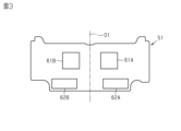
- 3 is a top view showing a first surface of the control board of FIG. 2.
- 3 is a bottom view showing a second surface of the control board of FIG. 2.
- FIG. 3 is a top view showing a first surface of the power board of FIG. 2 .
- FIG. 3 is a bottom view showing a second surface of the power board of FIG. 2 .
- FIG. 2 is a cross-sectional view showing a main part of the motor device of FIG. 1 .
- the motor device is mounted, for example, on a steering device of a vehicle.
- the steering device of a vehicle has a steering mechanism 11.
- the steering mechanism 11 is a mechanical part that steers steered wheels 12 of the vehicle in response to the steering of a steering wheel.
- the steering mechanism 11 has a pinion shaft 21, a steered shaft 22, and a housing 23.
- the housing 23 rotatably supports the pinion shaft 21.
- the housing 23 also accommodates the steered shaft 22 so that it can reciprocate in the axial direction.
- the pinion shaft 21 is arranged to intersect with the steered shaft 22.
- the pinion teeth 21a of the pinion shaft 21 mesh with the rack teeth 22a of the steered shaft 22. Both ends of the steered shaft 22 are connected to the steered wheels 12 via rack ends 24 and tie rods 25.
- the steering device is a steer-by-wire type steering device or an electric power steering device. If the steering device is a steer-by-wire type steering device, the pinion shaft 21 is not mechanically connected to the steering wheel. If the steering device is an electric power steering device, the pinion shaft 21 is mechanically connected to the steering wheel via a steering shaft.
- the steering mechanism 11 includes a motor device 31, a transmission mechanism 32, and a conversion mechanism 33.
- the motor device 31 is a generating source of a steering force applied to the steered shaft 22.
- the steering force is a force for steering the steered wheels 12.
- the transmission mechanism 32 is, for example, a belt transmission mechanism.
- the transmission mechanism 32 transmits the rotation of the motor 31 to the conversion mechanism 33.
- the conversion mechanism 33 is, for example, a ball screw mechanism.
- the conversion mechanism 33 converts the rotation transmitted via the transmission mechanism 32 into axial motion of the steered shaft 22.
- the steered angle ⁇ w of the steered wheels 12 is changed by the axial movement of the steered shaft 22.
- the steered shaft 22 is a drive target of the motor device 31.
- the motor device 31 functions as a steering motor.
- the steering motor generates a steering force for steering the steered wheels 12.
- the motor device 31 functions as an assist motor.
- the assist motor generates an assist force for assisting the operation of the steering wheel.
- the motor device 31 has a motor 40 and a control device 50.
- the motor 40 is, for example, a three-phase brushless motor.
- the motor 40 has, for example, two winding groups.
- the control device 50 is attached to an axial end of the motor 40. The control device 50 independently controls the power supply to the two winding groups.
- the control device 50 has a control board 51, a power board 52, a connector assembly 53, and a cover 53.
- the control board 51 has electronic components for controlling the power supply to the motor 40.
- the power board 52 has electronic components for supplying power to the motor 40 through control by the control board 51.
- An axial end of the motor 40 has a board accommodation portion 40A.
- the control board 51 is accommodated inside the board accommodation portion 40A.
- the power board 52 is attached to an axial end of the motor 40 so as to cover the control board 51.
- the power board 52 is disposed at a position farther from the motor 40 than the control board 51 in the axial direction of the motor 40.
- the control board 51 is a first board of the motor device 31.
- the power board 52 is a second board of the motor device 31.
- the connector assembly 53 is made of synthetic resin.
- the connector assembly 53 has a first power connector 53A and a second power connector 53B.
- the first power connector 53A extends in the opposite direction to the motor 40 and opens in the opposite direction to the motor 40.
- the first power connector 53A has a power terminal and a ground terminal.
- a power plug, which is a mating partner, is fitted into the first power connector 53A.
- the power plug is provided at a first end of a power line.
- the second end of the power line is connected to a DC power source such as an on-board battery. Power from the DC power source is supplied to the control board 51 and the power board 52 via the power terminal and the ground terminal.
- the second power connector 53B has a configuration similar to that of the first power connector 53A.
- the DC power source corresponds to an external power source.
- the connector assembly 53 has a first signal connector 53C and a second signal connector 53D.
- the first signal connector 53C extends in the opposite direction to the motor 40.
- the first signal connector 53C has a signal terminal.
- a mating signal plug is fitted into the first signal connector 53C.
- the signal plug is provided at a first end of a signal line.
- the second end of the signal line is connected to a vehicle control device.
- the control board 51 and the vehicle control device exchange signals via the signal terminal.
- the second signal connector 53D has a configuration similar to that of the first signal connector 53C.
- the cover 54 is made of synthetic resin.
- the cover 54 is a box-shaped body that opens toward the motor 40.
- An end wall of the cover 54 has a fitting hole 54A.
- the outer periphery of the connector assembly 53 fits into the fitting hole 54A.
- Each connector (53A, 53B, 53C, 54C) of the connector assembly 53 passes through the fitting hole 54A and protrudes from the end wall of the cover 54 to the outside of the cover 53.
- the cover 54 is attached to the axial end of the motor 40.
- the cover 54 covers the end of the motor 40 together with the connector assembly 53.
- control board 51 is, for example, in the shape of a rectangular flat plate.
- the control board 51 has a first surface and a second surface located opposite to each other.
- the first surface is the surface of the control board 51 located opposite to the power board 52 when the motor device 31 is assembled.
- the second surface is the surface of the control board 51 facing the power board 52 when the motor device 31 is assembled.
- the first surface of the control board 51 has a first microcomputer 61A and a second microcomputer 61B.
- the first microcomputer 61A and the second microcomputer 61B are arranged so as to be linearly symmetrical with respect to a first center line O1.
- the first center line O1 is, for example, a straight line passing through the center of the control board 51 when viewed from a direction perpendicular to the control board 51.
- the first surface has a first board-to-board connector 62A and a second board-to-board connector 62B.
- the first board-to-board connector 62A and the second board-to-board connector 62B are arranged so as to be linearly symmetrical with respect to the first center line O1.
- the second surface of the control board 51 has a first ground connection member 63A and a second ground connection member 63B.
- the first ground connection member 63A and the second ground connection member 63B are arranged so as to be symmetrical with respect to the first center line O1.
- the first ground connection member 63A is arranged, for example, at a position corresponding to the first board-to-board connector 62A or in its vicinity.
- the second ground connection member 63B is arranged, for example, at a position corresponding to the second board-to-board connector 62B or in its vicinity.
- the first ground connection member 63A and the second ground connection member 63B are each an elastic member made of metal and have elasticity in a direction perpendicular to the control board 51.
- the metal is, for example, copper, and is conductive.
- the power board 52 is, for example, flat.
- the power board 52 has a first surface and a second surface that are located opposite each other.
- the first surface is the surface of the power board 52 that is located opposite the control board 51 when the motor device 31 is assembled.
- the second surface is the surface of the power board 52 that faces the control board 51 when the motor device 31 is assembled.
- the first surface of the power board 52 has a first ripple capacitor 71A and a second ripple capacitor 71B.
- the first ripple capacitor 71A and the second ripple capacitor 71B are arranged so as to be symmetrical with respect to the second center line O2.
- the second center line O2 is, for example, a straight line passing through the center of the power board 52.
- the second center line O2 coincides with the first center line O1 of the control board 51.
- the first surface of the power board 52 has a first power supply filter 72A and a second power supply filter 72B.
- the first power supply filter 72A and the second power supply filter 72B are arranged so as to be symmetrical with respect to the second center line O2.
- the first power supply filter 72A and the second power supply filter 72B each have a capacitor and a coil.
- the first surface of the power board 52 has a first power terminal connection portion 73A and a second power terminal connection portion 73B.
- the first power terminal connection portion 73A and the second power terminal connection portion 73B are arranged so as to be linearly symmetrical with respect to the second center line O2.
- the first power terminal connection portion 73A is a portion of the power board 52 to which the power terminal and ground terminal of the first power connector 53A are connected.
- the second power terminal connection portion 73B is a portion of the power board 52 to which the power terminal and ground terminal of the second power connector 53B are connected.
- the first surface of the power board 52 has a first signal terminal connection portion 74A and a second signal terminal connection portion 74B.
- the first signal terminal connection portion 74A and the second signal terminal connection portion 74B are arranged so as to be symmetrical with respect to the second center line O2.
- the first signal terminal connection portion 74A is the portion of the power board 52 to which the signal terminal of the first signal connector 53C is connected.
- the second power supply signal connection portion 74B is the portion of the power board 52 to which the signal terminal of the second signal connector 53D is connected.
- the first surface of the power board 52 has a first power supply circuit 75A and a second power supply circuit 75B.
- the first power supply circuit 75A and the second power supply circuit 75B are arranged so as to be linearly symmetrical with respect to the second center line O2.
- the first power supply circuit 75A and the second power supply circuit 75B are each a chip-type integrated circuit.
- the first power supply circuit 75A converts the voltage of the on-board DC power supply to a voltage suitable for the operation of the first system of electrical circuits including the first microcomputer 61A.
- the second power supply circuit 75B converts the voltage of the on-board DC power supply to a voltage suitable for the operation of the second system of electrical circuits including, for example, the second microcomputer 61B.
- the conversion includes a process of lowering the voltage of the on-board DC power supply.
- the second surface of the power board 52 has a first inverter circuit 81A and a second inverter circuit 81B.
- the first inverter circuit 81A and the second inverter circuit 81B are arranged so as to be linearly symmetrical with respect to the second center line O2.
- the first inverter circuit 81A and the second inverter circuit 81B each have a plurality of switching elements.
- the switching elements are, for example, FETs (Field Effect Transistors).
- the switching elements of the first inverter circuit 81A perform a switching operation, thereby converting the DC power supplied from the DC power supply into three-phase AC power.
- the AC power generated by the first inverter circuit 81A is supplied to the first winding group of the motor 40 via a power supply path such as a bus bar.
- the switching elements of the second inverter circuit 81B perform a switching operation, thereby converting the DC power supplied from the DC power supply into three-phase AC power.
- the AC power generated by the second inverter circuit 81B is supplied to the second winding group of the motor 40 via a power supply path such as a bus bar.
- the second surface of the power board 52 has a first phase opening relay group 82A and a second phase opening relay group 82B.
- the first phase opening relay group 82A and the second phase opening relay group 82B are arranged so as to be linearly symmetrical with respect to the second center line O2.
- the first phase opening relay group 82A opens and closes the power supply paths for each of the three phases between the first inverter circuit 81A and the first winding group of the motor 40.
- the second phase opening relay group 82b opens and closes the power supply paths for each of the three phases between the second inverter circuit 81B and the second winding group of the motor 40.
- the phase opening relays may be, for example, FETs.
- the second surface of the power board 52 has a first power supply relay 83A and a second power supply relay 83B.
- the first power supply relay 83A and the second power supply relay 83B are arranged so as to be linearly symmetrical with respect to the second center line O2.
- the first power supply relay 83A opens and closes the power supply path between the on-board DC power supply and the first inverter circuit 81A.
- the second power supply relay 83B opens and closes the power supply path between the on-board DC power supply and the second inverter circuit 81B.
- the DC power supply is, for example, a battery.
- the power supply relay may be, for example, a FET.
- the second surface of the power board 52 has a first pre-driver 84A and a second pre-driver 84B.
- the first pre-driver 84A and the second pre-driver 84B are arranged so as to be linearly symmetrical with respect to the second center line O2.
- the first pre-driver 84A generates a drive signal for the first inverter circuit 81A based on a command from the first microcomputer 61A.
- the second pre-driver 84B generates a drive signal for the second inverter circuit 81B based on a command from the second microcomputer 61B.
- the second surface of the power board 52 has a third inter-board connector 85A and a fourth inter-board connector 85B.
- the third inter-board connector 85A and the fourth inter-board connector 85B are arranged so as to be linearly symmetrical with respect to the second center line O2.
- the third inter-board connector 85A is arranged at a position corresponding to the first inter-board connector 62A when the motor device 31 is assembled.
- the fourth inter-board connector 85B is arranged at a position corresponding to the second inter-board connector 62B when the motor device 31 is assembled.
- the second surface of the power board 52 has a rotation angle sensor 86.
- the rotation angle sensor 86 is disposed near the center of the second surface.
- the rotation angle sensor 86 is located on the second center line O2.
- the rotation angle sensor 86 is a magnetic sensor.
- the magnetic sensor is, for example, an MR sensor (Magneto Resistive Sensor).
- the rotation angle sensor 86 detects the rotation angle of the motor 40.
- the first microcomputer 61A generates a command for the first pre-driver 84A based on the rotation angle of the motor 40 detected through the rotation angle sensor 86.
- the second microcomputer 61B generates a command for the second pre-driver 84B based on the rotation angle of the motor 40 detected through the rotation angle sensor 86.
- the motor 40 has a motor case 41 and a lid 42.
- An end of the motor case 41 is open in the axial direction.
- the end is the end of the motor case 41 on which the control device 50 is mounted.
- the lid 42 is fitted into the opening of the motor case 41 to close the opening.
- the lid 42 functions as an end wall of the motor case 41 in the axial direction.
- the motor case 41 and the lid 42 are each made of metal.
- the metal is, for example, iron or an aluminum alloy.
- the motor 40 has an output shaft 43.
- the output shaft 43 is rotatably supported on the inner circumferential surface of the motor case 41.
- An end of the output shaft 43 passes through the lid 42 in the axial direction without contact.
- the end is the end of the output shaft 43 that is closer to the control device 50.
- a magnet 43B is fixed to the end of the output shaft 43 by a holder 43A.
- a spacer 43C is interposed between the end of the output shaft 43 and the magnet 43B.
- the holder 43A and the spacer 43C are each made of a non-magnetic material such as synthetic resin.
- the control board 51 is accommodated inside the board accommodating section 40A.
- the end of the second ground connection member 63B opposite the control board 51 is in contact with the inner end wall of the board accommodating section 40A.
- the second ground connection member 63B is maintained in a slightly compressed state in a direction perpendicular to the control board 51.
- the end of the first ground connection member 63A opposite the control board 51 is also maintained in contact with the inner end wall of the board accommodating section 40A.
- the first ground connection member 63A is maintained in a slightly compressed state in a direction perpendicular to the control board 51.
- the power board 52 is supported by the lid 42 so as to cover the control board 51.
- the rotation angle sensor 86 faces the magnet 43B in the axial direction via the holder 43A.
- the fourth board-to-board connector 85B is connected to the second board-to-board connector 62B.
- the third board-to-board connector 85A is maintained in a state connected to the first board-to-board connector 62A.
- the second power connector 53B has a power terminal 53E and a ground terminal 53F.
- the power terminal 53E and the ground terminal 53F each have a first end and a second end.
- the first end is located inside the peripheral wall of the second power connector 53B.
- the second end penetrates the power board 52 in a direction perpendicular to the power board 52.
- the second end is connected to the power board 52 by soldering.
- the first power connector 53A also has a power terminal 53E and a ground terminal 53F.
- the second signal connector 53D has a plurality of signal terminals 53G.
- the signal terminals 53G have a first end and a second end. The first end is located inside the peripheral wall of the second signal connector 53D. The second end penetrates the power board 52 in a direction perpendicular to the power board 52. The second end is connected to the power board 52 by soldering.
- the first signal connector 53C also has a plurality of signal terminals 53G.
- the power board 52 is connected to the positive terminal of the DC power supply via the power supply terminal 53E.
- the power board 52 is connected to the negative terminal of the DC power supply via the ground terminal 53F.
- DC power from the DC power supply is supplied to the power board 52 via the power supply terminal 53E and the ground terminal 53F.
- DC power is supplied to the control board 51 via the first board-to-board connector 62A and the third board-to-board connector 85A, and the second board-to-board connector 62B and the fourth board-to-board connector 85B.
- the power board 52 is connected to the vehicle control device via signal terminal 53G.
- the power board 52 is capable of sending and receiving signals to and from the vehicle control device via signal terminal 53G.
- the control board 52 is capable of sending and receiving signals to and from the vehicle control device via the first inter-board connector 62A and the third inter-board connector 85A, as well as the second inter-board connector 62B and the fourth inter-board connector 85B.
- the control board 51 is fixed to the connector assembly 53.
- the connector assembly 53 has a plurality of first support pillars 53H. In Fig. 7, only one first support pillar 53H is shown.
- the first support pillar 53H is provided at the end of the connector assembly 53 opposite the power connectors (53A, 53B).
- the first support pillar 53H extends toward the lid 42.
- the control board 51 is fixed to the tip of the first support pillar 53H with a screw 53I. The tip is the end of the first support pillar 53H closer to the lid 42.
- the power board 52 is fixed to the connector assembly 53.
- the connector assembly 53 has a plurality of second pillars 53J.
- the second pillars 53J are provided at the end of the connector assembly 53 opposite the power connectors (53A, 53B).
- the second pillars 53J extend toward the lid 42.
- the length by which the second pillars 53J protrude from the connector assembly 53 is shorter than the length by which the first pillars 53H protrude from the connector assembly 53.
- the power board 52 is fixed to the tip of the second pillar 53J with a screw 53K.
- the tip is the end of the second pillar 53J closer to the lid 42.
- the power board 52 is also fixed to the lid 42.
- the lid 42 has multiple support parts 42A. In FIG. 7, only one support part 42A is shown.
- the support part 42A is provided on the axially outer end face of the lid 42.
- the power board 52 is fixed to the tip of the support part 42A with a screw 42B. The tip is the end of the support part 42A that is farther from the axially outer end face of the lid 42.
- the lid 42 has a board accommodating section 40A and a heat dissipation section 40B.
- the board accommodating section 40A and the heat dissipation section 40B are provided at the axial end of the lid 42. The end is the end of the lid 42 on the axial outer side.
- the board accommodating section 40A and the heat dissipation section 40B are adjacent to each other in a direction perpendicular to the axial direction.
- a step is provided between the board accommodating section 40A and the heat dissipation section 40B. That is, the axial position of the end wall surface of the board accommodating section 40A and the axial position of the end wall surface of the heat dissipation section 40A are different from each other.
- the end wall surface of the board accommodating section 40A is farther from the end wall of the cover 54 in the axial direction than the end wall surface of the heat dissipation section 40B.
- the end wall surface of the board accommodating section 40A is located axially inside the motor 40 than the end wall surface of the heat dissipation section 40B.
- the end wall surface of the board accommodating section 40A is the first surface of the lid 42.
- the end wall surface of the heat dissipation section 40B is the second surface of the lid 42.
- the heat dissipation section 40B is the portion of the lid 42 that exchanges heat with the power board 52.
- An end wall surface of the board accommodating portion 40A faces the control board 51 in the axial direction.
- a first gap D1 is formed between the end wall surface of the board accommodating portion 40A and the control board 51.
- the power board 52 has a first portion 52A and a second portion 52B.
- the first portion 52A is a portion of the power board 52 that faces the control board 51.
- the second portion 52B is a portion of the power board 52 that faces an end wall surface of the heat dissipation section 40B. In other words, the second portion 52B does not overlap with the control board 51 in the axial direction.
- a second gap D2 is formed between the second portion 52B and the end wall surface of the heat dissipation section 40B.
- the second gap D2 is narrower than the first gap D1.
- the thermal resistance between the second portion 52B of the power board 52 and the heat dissipation section 40B is smaller than the thermal resistance between the control board 51 and the end wall surface of the board accommodating section 40A. Furthermore, a part of the power board 52 is in contact with the lid 42. Therefore, the thermal resistance of the heat dissipation path between the power board 52 and the lid 42 is smaller than the thermal resistance of the heat dissipation path between the control board 51 and the lid 42.
- Thermal resistance is a numerical representation of how difficult it is for heat to be transmitted. The higher the thermal resistance, the more difficult it is for heat to be transmitted, and the lower the thermal resistance, the easier it is for heat to be transmitted.
- the thermal resistance between the control board 51 and the lid 42, and the thermal resistance between the second part 52B of the power board 52 and the lid 42 include thermal resistance due to thermal radiation. Radiant heat attenuates in proportion to the square of the distance between the heat source and the object. Radiant heat attenuates to 1/4 when the distance is doubled, and to 1/9 when the distance is tripled. "/" indicates division. For this reason, heat generated from the second part 52B of the power board 52 is more easily transferred to the lid 42 than heat generated from the control board 51.
- the power board 52 has heat generating elements.
- Heat generating elements are electronic components that generate heat when electricity is applied.
- the heat generating elements include high heat generating elements.
- the high heat generating elements include, for example, the first power supply circuit 75A, the second power supply circuit 75B, the first pre-driver 84A, and the second pre-driver 84B.
- the high heat generating elements also include, for example, the switching element 81A1 of the first inverter circuit 81A and the switching element 81B1 of the second inverter circuit 81B.
- the switching element 81B1 is one of the electronic components that generates a particularly large amount of heat among the high heat generating elements.
- the heat generating amounts of the first power supply circuit 75A, the second power supply circuit 75B, the first pre-driver 84A, and the second pre-driver 84B are less than the heat generating amounts of the first inverter circuit 81A and the second inverter circuit 81B.
- the first power supply circuit 75A, the second power supply circuit 75B, the first pre-driver 84A, and the second pre-driver 84B are provided, for example, in the first portion 52A of the power board 52. However, in FIG. 7, only the second power supply circuit 75B and the second pre-driver 84B are shown.
- the switching elements 81A1 and 81B1 are provided, for example, in the second portion 52B of the power board 52.
- the surfaces of the switching elements 81A1 and 81B1 opposite to the second surface of the power board 52 are in contact with the heat dissipation portion 40B of the lid 42 via the heat dissipation materials 81A2 and 81B2. However, in FIG. 7, only the switching element 81B1 is shown.
- the heat dissipation materials 81A2, 81B2 are, for example, heat dissipation grease.
- Heat dissipation grease has high thermal conductivity.
- the control board 51 has heat generating elements.
- the heat generating elements include low heat generating elements.
- the low heat generating elements include, for example, the first microcomputer 61A and the second microcomputer 61B.
- the amount of heat generated by the low heat generating elements is less than the amount of heat generated by the high heat generating elements.
- the high heat generating elements include, for example, the first power supply circuit 75A, the second power supply circuit 75B, the first pre-driver 84A, the second pre-driver 84B, and the switching elements 81A1 and 81B1.
- Heat dissipation path A1 is a heat transfer path between the high heat generating elements of the power board 52 and the lid 42. Heat dissipation path A1 includes the power board 52, the contact portion between the power board 52 and the lid 42, and the non-contact portion between the power board 52 and the lid 42.
- Part of the heat is transferred to the lid 42 by thermal conduction through the power board 52 and the contact area between the power board 52 and the lid 42.
- the heat generated by the switching elements 81A1, 81B1 is efficiently transferred to the lid 42 via the heat dissipation materials 81A2, 81B2.
- Part of the heat is transferred directly to the lid 42 by radiation.
- the heat transferred to the lid 42 is dissipated to the outside through the motor case 41. Part of the heat is also transferred to the atmosphere by convection.
- the control board 51 is not in direct contact with the lid 42. Therefore, the heat dissipation of the control board 51 is lower than that of the power board 52. However, the control board 51 does not have high heat generating elements. High heat generating elements are provided on the power board 52, which is separate from the control board 51. Therefore, the first microcomputer 61A and the second microcomputer 61B are less susceptible to the effects of heat from the surroundings. Therefore, it is possible to keep the temperatures of the first microcomputer 61A and the second microcomputer 61B below a set heat resistance temperature. The heat generated by the first microcomputer 61A and the second microcomputer 61B is transferred to the atmosphere or the lid 42 by, for example, convection or radiation.
- the motor 40 has a motor case 41 and a lid 42 attached to an end of the motor case 41 in the axial direction.
- the control board 51 has a low heat generating element.
- the control board 51 is arranged to face a part of the lid 42 in the axial direction of the motor 40.
- the power board 52 has a high heat generating element that generates more heat than the low heat generating element.
- the power board 52 is arranged on the opposite side of the control board 51 from the lid 42 in the axial direction of the motor 40. In other words, the control board 51 is arranged between the lid 42 and the power board 52 in the axial direction of the motor 40.
- the power board 52 has a first portion 52A facing the control board 51 and a second portion 52B facing the lid 42. The thermal resistance between the second portion 52B of the power board 52 and the lid 42 is smaller than the thermal resistance between the control board 51 and the lid 42.
- the low heat generating elements and the high heat generating elements are provided on separate boards. Therefore, the heat from the high heat generating elements is less likely to be transferred to the control board 51 and, ultimately, the low heat generating elements. Because the temperature rise of the low heat generating elements is suppressed, it is possible to eliminate the need for a configuration for dissipating the heat generated by the low heat generating elements. For example, there is no need to bring the end wall surface of the board accommodating section 40A into contact with the control board 51 or to interpose a heat dissipating material between the end wall surface of the board accommodating section 40A and the control board 51.
- the heat generated by the high heat generating element is efficiently transferred to the lid 42 via the power board 52.
- the thermal resistance between the second part 52B of the power board 52 and the lid 42 is configured to be smaller. If the thermal resistance between the second part 52B of the power board 52 and the lid 42 is smaller than the thermal resistance between the control board 51 and the lid 42, which does not require a configuration for heat dissipation, for example, sufficient heat dissipation can be ensured for the heat generated by the high heat generating element. For this reason, there is no need to provide a separate heat sink at the end of the motor 40 to ensure heat dissipation.
- the size of the motor device 31, particularly the size in the axial direction can be made smaller by the amount that a heat sink is not provided. The weight of the motor device 31 can also be reduced by the amount that a heat sink is not provided.
- the axial distance D2 between the second portion 52B of the power board 52 and the lid 42 is shorter than the axial distance D1 between the control board 51 and the lid 42.
- the lid 42 has a board accommodating section 40A and a heat dissipation section 40B.
- the end wall surface of the board accommodating section 40A is located axially inward of the motor 40 relative to the end wall surface of the heat dissipation section 40B.
- the end wall surface of the board accommodating section 40A is the surface of the lid 42 that faces the control board 51.
- the end wall surface of the heat dissipation section 40B is the surface of the lid 42 that faces the second portion 52B of the power board 52.
- the motor device 31 has a connector assembly 53 made of synthetic resin.
- the connector assembly 53 is disposed at a position farther from the lid 42 than the power board 52 in the axial direction of the motor 40. In other words, the connector assembly 53 is disposed on the opposite side of the lid 42 from the power board 52 in the axial direction of the motor 40.
- the connector assembly 53 holds a plurality of terminals for supplying power or signals to the control board 51 and the power board 52.
- the terminals include a power terminal 53E, a ground terminal 53F, and a signal terminal 53G.
- the control board 51 is fixed to the connector assembly 53.
- the power board 52 is fixed to both the connector assembly 53 and the lid 42. With this configuration, the heat generated by the high heat generating element is transferred to the lid 42 via the power board 52. Since the control board 51 is not fixed to the lid 42, the heat transferred to the lid 42 is not easily transferred from the lid 42 to the control board 51. This suppresses the temperature rise of the control board 51.
- the control board 51 and the power board 52 exchange power and signals via board-to-board connectors (62A, 85A, 62B, 85B).
- the power board 52 has power supply circuits (75A, 75B).
- the power supply circuit converts the voltage of the on-board DC power supply into a voltage suitable for the operation of an electrical circuit including a microcomputer (61A, 61B) provided on the control board 51. Only the voltage converted by the power supply circuit is supplied to the control board 51 via the board-to-board connector. The voltage converted by the power supply circuit is lower than the voltage of the on-board DC power supply. For this reason, heat generation by the control board 51 can be suppressed compared to when, for example, a voltage from an on-board DC power supply is supplied to the control board 51.
- the high heat generating element includes switching elements 81A1, 81B1, pre-drivers (84A, 84B), and power supply circuits (75A, 75B).
- the switching elements 81A1, 81B1 are arranged in the second portion 52B of the power board 52.
- the pre-drivers (84A, 84B) and power supply circuits (75A, 75B) are arranged in the first portion 52A of the power board 52.
- the first portion 52A of the power board 52 is the portion of the power board 52 that faces the control board 51. For this reason, there is a risk that heat may be transferred from the first portion 52A of the power board 52 to the control board 51, for example, by radiation.
- the switching elements 81A1, 81B are provided on the surface of the power board 52 that faces the lid 42.
- the switching elements 81A1, 81B are in contact with the lid 42 via the heat dissipation materials 81A2, 81B2. With this configuration, the heat generated by the switching elements 81A1, 81B is efficiently transferred to the lid 42 via the heat dissipation materials 81A2, 81B2.
- the motor 40 has two control systems and two power supply systems.
- the number of electronic components on the control board 51 and the power board 52 is twice as many as when the motor 40 has one control system and one power supply system. This increases the mounting density of electronic components on the board. Therefore, for example, when high heat generating elements and low heat generating elements are mounted on the same board, the electronic components transfer heat to each other, which makes it easier for the temperature of the electronic components to rise.
- the motor device 31 it is necessary to provide the motor device 31 with a structure for suppressing temperature rise in the microcomputers (61A, 61B).
- the microcomputers (61A, 61B), the pre-drivers (81A, 81B), and the power supply circuits (75A, 75B) are distributed on different substrates. This suppresses heat transfer between the microcomputers (61A, 61B) and the pre-drivers (81A, 81B), and between the microcomputers (61A, 61B) and the power supply circuits (75A, 75B). This suppresses the temperature rise of the microcomputers (61A, 61B). There is no need to provide a separate configuration for suppressing the temperature rise of the microcomputers (61A, 61B) in the motor device 31. This embodiment is suitable for a motor device 31 having multiple control systems and multiple power supply systems.
- This embodiment may be modified as follows.
- the heat dissipation materials 81A2, 81B2 may be omitted.
- a gap is formed between the switching elements 81A1, 81B1 and the heat dissipation portion 40B.
- the gap is very small. Therefore, the heat generated by the switching elements 81A1, 81B1 is efficiently transferred to the heat dissipation portion 40B by, for example, radiation.
- the power board 52 may be fixed to the connector assembly 53 and the motor case 41.
- a support portion for supporting the power board 52 is provided on the motor case 41. Even in this way, the heat dissipation properties of the power board 52 can be ensured.
- the motor 40 may have one system of windings.
- the control system and power supply system of the motor 40 may each be one system.
- the connector assembly 53 may be configured in such a way that the first power connector 53A and the first signal connector 53C, or the second power connector 53B and the second signal connector 53D, are omitted.
Landscapes
- Engineering & Computer Science (AREA)
- Power Engineering (AREA)
- Microelectronics & Electronic Packaging (AREA)
- Chemical & Material Sciences (AREA)
- Combustion & Propulsion (AREA)
- Transportation (AREA)
- Mechanical Engineering (AREA)
Priority Applications (4)
| Application Number | Priority Date | Filing Date | Title |
|---|---|---|---|
| EP23924047.6A EP4672561A4 (en) | 2023-02-22 | 2023-02-22 | ENGINE DEVICE |
| JP2025502017A JPWO2024176394A1 (https=) | 2023-02-22 | 2023-02-22 | |
| PCT/JP2023/006488 WO2024176394A1 (ja) | 2023-02-22 | 2023-02-22 | モータ装置 |
| CN202380094455.1A CN120677618A (zh) | 2023-02-22 | 2023-02-22 | 马达装置 |
Applications Claiming Priority (1)
| Application Number | Priority Date | Filing Date | Title |
|---|---|---|---|
| PCT/JP2023/006488 WO2024176394A1 (ja) | 2023-02-22 | 2023-02-22 | モータ装置 |
Publications (1)
| Publication Number | Publication Date |
|---|---|
| WO2024176394A1 true WO2024176394A1 (ja) | 2024-08-29 |
Family
ID=92500339
Family Applications (1)
| Application Number | Title | Priority Date | Filing Date |
|---|---|---|---|
| PCT/JP2023/006488 Ceased WO2024176394A1 (ja) | 2023-02-22 | 2023-02-22 | モータ装置 |
Country Status (4)
| Country | Link |
|---|---|
| EP (1) | EP4672561A4 (https=) |
| JP (1) | JPWO2024176394A1 (https=) |
| CN (1) | CN120677618A (https=) |
| WO (1) | WO2024176394A1 (https=) |
Citations (6)
| Publication number | Priority date | Publication date | Assignee | Title |
|---|---|---|---|---|
| JP2002345211A (ja) * | 2001-05-17 | 2002-11-29 | Mitsubishi Electric Corp | 電動式パワーステアリング装置 |
| JP2011200022A (ja) * | 2010-03-19 | 2011-10-06 | Mitsubishi Electric Corp | 電動式駆動装置およびそれを搭載した電動式パワーステアリング装置 |
| JP2012135187A (ja) * | 2010-11-30 | 2012-07-12 | Jtekt Corp | モータ制御装置及びこれを備える電動パワーステアリング装置 |
| JP2016158455A (ja) * | 2015-02-26 | 2016-09-01 | 株式会社豊田自動織機 | インバータ装置および電動圧縮機 |
| JP2021065017A (ja) * | 2019-10-11 | 2021-04-22 | 株式会社ジェイテクト | モータ装置 |
| JP2022144197A (ja) | 2021-03-18 | 2022-10-03 | 株式会社デンソー | 駆動装置 |
Family Cites Families (1)
| Publication number | Priority date | Publication date | Assignee | Title |
|---|---|---|---|---|
| JP6838501B2 (ja) * | 2017-06-14 | 2021-03-03 | 株式会社デンソー | 電子制御装置、および、これを用いた電動パワーステアリング装置 |
-
2023
- 2023-02-22 JP JP2025502017A patent/JPWO2024176394A1/ja active Pending
- 2023-02-22 WO PCT/JP2023/006488 patent/WO2024176394A1/ja not_active Ceased
- 2023-02-22 CN CN202380094455.1A patent/CN120677618A/zh active Pending
- 2023-02-22 EP EP23924047.6A patent/EP4672561A4/en active Pending
Patent Citations (6)
| Publication number | Priority date | Publication date | Assignee | Title |
|---|---|---|---|---|
| JP2002345211A (ja) * | 2001-05-17 | 2002-11-29 | Mitsubishi Electric Corp | 電動式パワーステアリング装置 |
| JP2011200022A (ja) * | 2010-03-19 | 2011-10-06 | Mitsubishi Electric Corp | 電動式駆動装置およびそれを搭載した電動式パワーステアリング装置 |
| JP2012135187A (ja) * | 2010-11-30 | 2012-07-12 | Jtekt Corp | モータ制御装置及びこれを備える電動パワーステアリング装置 |
| JP2016158455A (ja) * | 2015-02-26 | 2016-09-01 | 株式会社豊田自動織機 | インバータ装置および電動圧縮機 |
| JP2021065017A (ja) * | 2019-10-11 | 2021-04-22 | 株式会社ジェイテクト | モータ装置 |
| JP2022144197A (ja) | 2021-03-18 | 2022-10-03 | 株式会社デンソー | 駆動装置 |
Non-Patent Citations (1)
| Title |
|---|
| See also references of EP4672561A1 |
Also Published As
| Publication number | Publication date |
|---|---|
| EP4672561A1 (en) | 2025-12-31 |
| EP4672561A4 (en) | 2026-03-25 |
| JPWO2024176394A1 (https=) | 2024-08-29 |
| CN120677618A (zh) | 2025-09-19 |
Similar Documents
| Publication | Publication Date | Title |
|---|---|---|
| JP6172217B2 (ja) | 駆動装置、および、これを用いた電動パワーステアリング装置 | |
| JP6443055B2 (ja) | 駆動装置、および、駆動装置の製造方法 | |
| JP6179476B2 (ja) | 駆動装置、および、これを用いた電動パワーステアリング装置 | |
| JP6582568B2 (ja) | 駆動装置、および、これを用いた電動パワーステアリング装置 | |
| JP5528329B2 (ja) | 制御装置一体型電動パワーステアリング装置用モータおよび電動パワーステアリング装置 | |
| JP7004289B2 (ja) | モータ制御装置および電動パワーステアリング装置 | |
| JP5572608B2 (ja) | モータ駆動装置 | |
| JP2016036245A (ja) | 駆動装置、および、これを用いた電動パワーステアリング装置 | |
| JP2011229229A (ja) | 電動機の駆動装置及びこれを用いた電動装置 | |
| JP2016140150A (ja) | 回転電機 | |
| JP2016034205A (ja) | 駆動装置、および、これを用いた電動パワーステアリング装置 | |
| WO2012060123A1 (ja) | 電動式パワーステアリング用パワーモジュールおよびこれを用いた電動式パワーステアリング駆動制御装置 | |
| WO2015122069A1 (ja) | 制御装置付き回転電機、電動パワーステアリング装置および制御装置付き回転電機の製造方法 | |
| EP3806294B1 (en) | Motor device | |
| JP6064479B2 (ja) | 制御装置および同装置を備えるモータユニット | |
| US20120014070A1 (en) | Control device | |
| JP2008037131A (ja) | 電動パワーステアリング装置 | |
| JP7063747B2 (ja) | 電動駆動装置及び電動パワーステアリング装置 | |
| CN114946117A (zh) | 功率变换装置及机电一体型功率变换装置 | |
| WO2020008905A1 (ja) | 電動駆動装置及び電動パワーステアリング装置 | |
| JP4582182B2 (ja) | 電動式パワーステアリング装置 | |
| WO2024176394A1 (ja) | モータ装置 | |
| JP5967425B2 (ja) | 電動パワーステアリング装置 | |
| JP2019062588A (ja) | 電動駆動装置及び電動パワーステアリング装置 | |
| JP2009012631A (ja) | 電動パワーステアリング装置 |
Legal Events
| Date | Code | Title | Description |
|---|---|---|---|
| 121 | Ep: the epo has been informed by wipo that ep was designated in this application |
Ref document number: 23924047 Country of ref document: EP Kind code of ref document: A1 |
|
| ENP | Entry into the national phase |
Ref document number: 2025502017 Country of ref document: JP Kind code of ref document: A |
|
| WWE | Wipo information: entry into national phase |
Ref document number: 2025502017 Country of ref document: JP |
|
| WWE | Wipo information: entry into national phase |
Ref document number: 202380094455.1 Country of ref document: CN |
|
| WWP | Wipo information: published in national office |
Ref document number: 202380094455.1 Country of ref document: CN |
|
| WWE | Wipo information: entry into national phase |
Ref document number: 2023924047 Country of ref document: EP |
|
| NENP | Non-entry into the national phase |
Ref country code: DE |
|
| ENP | Entry into the national phase |
Ref document number: 2023924047 Country of ref document: EP Effective date: 20250922 |
|
| ENP | Entry into the national phase |
Ref document number: 2023924047 Country of ref document: EP Effective date: 20250922 |
|
| WWP | Wipo information: published in national office |
Ref document number: 2023924047 Country of ref document: EP |