WO2024176383A1 - 制御装置 - Google Patents
制御装置 Download PDFInfo
- Publication number
- WO2024176383A1 WO2024176383A1 PCT/JP2023/006455 JP2023006455W WO2024176383A1 WO 2024176383 A1 WO2024176383 A1 WO 2024176383A1 JP 2023006455 W JP2023006455 W JP 2023006455W WO 2024176383 A1 WO2024176383 A1 WO 2024176383A1
- Authority
- WO
- WIPO (PCT)
- Prior art keywords
- torque
- slip ratio
- control device
- engine
- drive source
- Prior art date
- Legal status (The legal status is an assumption and is not a legal conclusion. Google has not performed a legal analysis and makes no representation as to the accuracy of the status listed.)
- Ceased
Links
Images





Classifications
-
- F—MECHANICAL ENGINEERING; LIGHTING; HEATING; WEAPONS; BLASTING
- F16—ENGINEERING ELEMENTS AND UNITS; GENERAL MEASURES FOR PRODUCING AND MAINTAINING EFFECTIVE FUNCTIONING OF MACHINES OR INSTALLATIONS; THERMAL INSULATION IN GENERAL
- F16D—COUPLINGS FOR TRANSMITTING ROTATION; CLUTCHES; BRAKES
- F16D48/00—External control of clutches
- F16D48/02—Control by fluid pressure
-
- F—MECHANICAL ENGINEERING; LIGHTING; HEATING; WEAPONS; BLASTING
- F16—ENGINEERING ELEMENTS AND UNITS; GENERAL MEASURES FOR PRODUCING AND MAINTAINING EFFECTIVE FUNCTIONING OF MACHINES OR INSTALLATIONS; THERMAL INSULATION IN GENERAL
- F16H—GEARING
- F16H61/00—Control functions within control units of change-speed- or reversing-gearings for conveying rotary motion ; Control of exclusively fluid gearing, friction gearing, gearings with endless flexible members or other particular types of gearing
- F16H61/14—Control of torque converter lock-up clutches
Definitions
- the present invention relates to a control device.
- Patent Document 1 discloses a technology in which a control device for a front-rear wheel drive vehicle has a torque converter equipped with a lock-up mechanism capable of controlling the amount of engagement interposed between one of the front and rear wheels and the engine, the control device being equipped with a lock-up control means that controls the lock-up mechanism so that a target slip amount is set according to the driving state of the front-rear wheel drive vehicle, a motor driving force setting means that sets the driving force of the motor, and a correction means that corrects the target slip amount according to the driving force of the motor set by the motor driving force setting means.
- a control device for a front-rear wheel drive vehicle has a torque converter equipped with a lock-up mechanism capable of controlling the amount of engagement interposed between one of the front and rear wheels and the engine, the control device being equipped with a lock-up control means that controls the lock-up mechanism so that a target slip amount is set according to the driving state of the front-rear wheel drive vehicle, a motor driving force setting means that sets the driving force of
- the present invention provides a control device that makes it possible to appropriately control the slip ratio of a disconnecting device provided on a transmission path that transmits the torque of a first drive source, which has torque pulsation, and the torque of a second drive source to a drive wheel. This in turn contributes to improving energy efficiency.
- a control device that controls an engagement state of a disconnecting device provided on a transmission path that transmits a torque of a first drive source having torque pulsation and a torque of a second drive source to a drive wheel,
- the transmission path further includes a first elastic member and a second elastic member that are connected in series and have different damping characteristics from each other
- the control device includes: The slip ratio of the disconnecting device is controllable based on a target slip ratio according to the torque of the first drive source, the target slip ratio when the torque of the first drive source is a predetermined value is made different between a case where an added torque obtained by adding the torque of the first drive source and the torque of the second drive source is equal to or greater than a threshold value and a case where the added torque is less than the threshold value; It is a control device.
- the present invention provides a control device that makes it possible to appropriately control the slip ratio of a disconnecting device provided on a transmission path that transmits the torque of a first drive source having torque pulsation and the torque of a second drive source to a drive wheel, and that can ultimately contribute to improving energy efficiency.
- FIG. 1 is a diagram illustrating an example of a vehicle 1 according to an embodiment of the present invention.
- 2 is a diagram showing an example of a transmission TM provided in a vehicle 1.
- FIG. 2 is a diagram showing an example of a lock-up damper 136 of a lock-up clutch 134 of a vehicle 1.
- FIG. 5 is a diagram showing an example of the damping characteristics of a lock-up damper 136.
- FIG. FIG. 4 is a diagram showing an example of a high torque slip ratio map Mp1.
- FIG. 13 is a diagram showing an example of a low torque slip ratio map Mp2.
- 4 is a diagram showing an example of slip ratio control by the control device 30.
- FIG. FIG. 11 is a diagram showing an example of a heat generation protection slip ratio map Mp3.
- FIG. 13 is a diagram showing another example of slip ratio control by the control device 30.
- FIG. FIG. 4 is a diagram showing an example of a slip ratio correction amount map Mp4. 4 is a flowchart showing an example of a process executed by a control device 30.
- FIG. 13 is a diagram showing a modified example of the vehicle 1.
- the vehicle 1 in this embodiment is a so-called hybrid electric vehicle, and includes an engine 11 which is an example of a first drive source in the present invention, a motor generator 12 which is an example of a second drive source in the present invention, drive wheels DW, a transmission TM which constitutes at least a part of a power transmission path that transmits the torque of the engine 11 and the motor generator 12 to the drive wheels DW, a battery 20, a power conversion device 21, and a control device 30 which controls the entire vehicle 1.
- the control device 30 is an example of a control device in the present invention.
- thick solid lines indicate mechanical connections
- double dashed lines indicate electrical wiring
- solid arrows indicate control signals or detection signals.
- Engine 11 is an internal combustion engine that can switch between full-cylinder operation, in which all cylinders are activated, and cylinder deactivation operation, in which some cylinders are deactivated. More specifically, engine 11 outputs mechanical energy (power) generated by burning fuel (e.g., gasoline) supplied by an injector (not shown), by rotating and driving crankshaft 11a (see FIG. 2). The torque (power) output from engine 11 is transmitted to drive wheels DW via transmission TM mechanically connected to engine 11, and is used to drive vehicle 1.
- fuel e.g., gasoline
- injector not shown
- the torque (power) output from engine 11 is transmitted to drive wheels DW via transmission TM mechanically connected to engine 11, and is used to drive vehicle 1.
- the engine 11 is also mechanically connected to the motor generator 12.
- the motor generator 12 is, for example, a three-phase AC motor, and functions as an electric motor that outputs torque (power) when power is supplied to it. More specifically, the rotor (not shown) of the motor generator 12 is connected to the crankshaft 11a of the engine 11. For this reason, the torque at the shaft end of the crankshaft 11a of the power plant torque output from the power plant consisting of the engine 11 and the motor generator 12 (hereinafter also referred to as crank end torque) is the sum of the torque output from the engine 11 (hereinafter also referred to as engine torque) and the torque output from the motor generator 12 (hereinafter also referred to as motor torque). In other words, the crank end torque is an added torque (hereinafter also referred to simply as added torque) obtained by adding the engine torque and the motor torque together.
- added torque an added torque obtained by adding the engine torque and the motor torque together.
- the vehicle 1 is capable of motor assist, in which the motor generator 12 assists the engine 11 in driving the drive wheels DW (i.e., the vehicle 1 traveling).
- the engine 11 and the motor generator 12 are mechanically connected, it is possible for the engine 11 to drive the motor generator 12 in rotation, or for the motor generator 12 to drive the engine 11 in rotation.
- the engine 11 it is possible to start the engine 11 by cranking using the motor generator 12.
- the motor generator 12 is electrically connected to the battery 20 via a power conversion device 21.
- the battery 20 is, for example, a battery that has multiple storage cells connected in series and is configured to be able to output a predetermined voltage (for example, 50 to 200 V).
- a predetermined voltage for example, 50 to 200 V.
- a lithium-ion battery or a nickel-metal hydride battery can be used as the storage cells of the battery 20.
- the power conversion device 21 is configured with an inverter, a DC/DC converter (neither shown), etc., and is a device that converts power according to the control of the control device 30.
- the power conversion device 21 converts the DC power supplied from the battery 20 into three-phase AC power and supplies it to the motor generator 12, or converts the three-phase AC power supplied from the motor generator 12 into DC power and supplies it to the battery 20.
- the motor generator 12 is able to perform the motor assist described above by receiving power from the battery 20 via the power conversion device 21.
- the motor generator 12 also functions as a generator that generates electricity by being driven and rotated. As described above, the motor generator 12 can be driven and rotated by the engine 11, and can also be driven and rotated by input from the drive wheels DW side associated with braking of the vehicle 1, etc. The electricity generated by the motor generator 12 is supplied to the battery 20 via the power conversion device 21 and is used to charge the battery 20.
- the transmission TM is, for example, a multi-speed transmission having multiple speeds (e.g., seven speeds) and is provided in the power transmission path from the engine 11 and the motor generator 12 to the drive wheels DW. More specifically, as shown in FIG. 2, the transmission TM includes a torque converter 13 and a gear box 14.
- the torque converter 13 includes a pump impeller 131, a turbine runner 132, a stator 133, and a lock-up clutch 134.
- the pump impeller 131 is mechanically connected to the engine 11 and the motor generator 12 (specifically, the crankshaft 11a) and rotates together with the engine 11 and the motor generator 12 when they are rotated.
- the turbine runner 132 has a hydraulic oil inlet located close to the hydraulic oil outlet of the pump impeller 131, and is mechanically connected to the main shaft 141, which is the input shaft of the gearbox 14, and rotates together with the main shaft 141.
- the stator 133 is disposed between the turbine runner 132 and the pump impeller 131, and deflects the flow of hydraulic oil returning from the turbine runner 132 to the pump impeller 131.
- the stator 133 is supported by a housing (not shown) of the torque converter 13 via a one-way clutch 135.
- the torque converter 13 can transmit power (rotational power) from the pump impeller 131 to the turbine runner 132 via the hydraulic oil by circulating the hydraulic oil in a circulation path formed between the pump impeller 131 and the turbine runner 132.
- the lockup clutch 134 is an example of a disconnecting device in the present invention, and is a clutch that can connect and disconnect the mechanical connection between the engine 11 (specifically, the crankshaft 11a) and the main shaft 141. By engaging the lockup clutch 134, it becomes possible to transmit engine torque to the main shaft 141 via the lockup clutch 134. For example, when the lockup clutch 134 is fully engaged (in other words, when the slip ratio, which will be described later, is set to 100%), the main shaft 141 rotates in accordance with the rotation of the crankshaft 11a. On the other hand, the lockup clutch 134 can also slip to attenuate the rotational power of the crankshaft 11a and transmit it to the main shaft 141.
- the lock-up clutch 134 has a lock-up damper 136.
- the lock-up damper 136 is an elastic member (damper) for damping torque pulsation (torque fluctuation) of the engine 11 that is transmitted to the drive wheels DW when the lock-up clutch 134 is engaged (in other words, when the slip ratio, which will be described later, is greater than 0%).
- the lockup damper 136 has a so-called double damper structure having a first damper 136a and a second damper 136b connected in series and having different damping characteristics.
- the lockup damper 136 is configured so that the first damper 136a of the first damper 136a and the second damper 136b acts in a high torque range (first torque range) in which the added torque, which is the input torque to the lockup clutch 134 (i.e., the transmission TM), is equal to or greater than a predetermined boundary torque TQth, and the second damper 136b of the first damper 136a and the second damper 136b acts in a low torque range (second torque range) in which the added torque is less than the boundary torque TQth.
- first torque range the added torque
- TQth the second damper 136b of the first damper 136a and the second damper 136b acts in a low torque range (second torque range) in which the added torque is less than the boundary torque TQth.
- the first damper 136a and the second damper 136b may be, for example, two types of springs with different pitches connected together, or may be integrally formed as an unequal pitch spring.
- the first damper 136a is an example of the first elastic member in the present invention
- the second damper 136b is an example of the second elastic member in the present invention.
- the first damper 136a and the second damper 136b are provided along the circumferential direction of the crankshaft 11a and the main shaft 141, which are rotated by the engine torque and/or the motor torque (i.e., the additive torque). Furthermore, a wall portion 200 of a retaining member (e.g., the housing of the torque converter 13) that retains the first damper 136a and the second damper 136b is provided on the circumferential outer side of the first damper 136a and the second damper 136b.
- a retaining member e.g., the housing of the torque converter 13
- the gearbox 14 includes a main shaft 141 to which the output of the engine 11 or motor generator 12 is transmitted via at least one of the torque converter 13 and the lock-up clutch 134, a plurality of speed change mechanisms 142, 143 capable of changing the speed of the power transmitted to the main shaft 141, and an output member 144 including an output gear 144a that outputs the power changed in speed by one of the plurality of speed change mechanisms to the drive wheels DW.
- the multiple speed change mechanisms provided in the gearbox 14 include a first speed change mechanism 142 and a second speed change mechanism 143.
- the first speed change mechanism 142 includes a first speed change clutch 142a, a first drive gear 142b that rotates integrally with the main shaft 141 when the first speed change clutch 142a is engaged, and a first driven gear 142c that rotates integrally with the output member 144.
- the second speed change mechanism 143 includes a second speed change clutch 143a, a second drive gear 143b that rotates integrally with the main shaft 141 when the second speed change clutch 143a is engaged, and a second driven gear 143c that rotates integrally with the output member 144.
- FIG. 2 illustrates only the first transmission mechanism 142 and the second transmission mechanism 143 as the transmission mechanisms provided in the gearbox 14, but the gearbox 14 may also include transmission mechanisms (not shown) other than the first transmission mechanism 142 and the second transmission mechanism 143, for example.
- control device 30 is a device that controls the engine 11, the transmission TM, the power conversion device 21, etc. Furthermore, the control device 30 can also control the motor generator 12 through control of the power conversion device 21. With regard to the control of the motor generator 12, the control device 30 may directly control the motor generator 12, or may control the input/output of the battery 20.
- control device 30 controls the engine 11, the transmission TM, the power conversion device 21 (i.e., the motor generator 12), etc. based on the information (detection signals) received from these various sensors.
- Sensors connected to the control device 30 include, for example, an engine speed sensor 17 that detects the rotation speed (hereinafter also referred to as engine speed; see also NE in FIG. 2) of the engine 11 (in other words, the crankshaft 11a), a vehicle speed sensor 18 that detects the traveling speed (hereinafter also referred to as vehicle speed) of the vehicle 1, and a main shaft rotation speed sensor 19 (see FIG. 2) that detects the rotation speed of the main shaft 141 (hereinafter also referred to as main shaft rotation speed; see also NM in FIG. 2).
- engine speed sensor 17 that detects the rotation speed (hereinafter also referred to as engine speed; see also NE in FIG. 2) of the engine 11 (in other words, the crankshaft 11a)
- vehicle speed sensor 18 that detects the traveling speed (hereinafter also referred to as vehicle speed) of the vehicle 1
- main shaft rotation speed sensor 19 see FIG. 2 that detects the rotation speed of the main shaft 141 (hereinafter also referred to as main shaft rotation speed; see also
- sensors connected to the control device 30 include an AP sensor that detects the amount of operation of the accelerator pedal of the vehicle 1 (hereinafter also referred to as AP opening), a brake sensor that detects the amount of operation of the brake pedal of the vehicle 1, a gear position sensor that detects the gear stage of the transmission TM, a battery sensor that detects the output and temperature of the battery 20, and an intake pressure sensor that detects the intake pressure (intake pipe pressure) of the engine 11 (all not shown).
- an atmospheric pressure sensor (not shown) that detects atmospheric pressure may be connected to the control device 30.
- control device 30 controls the engagement state of each clutch of the transmission TM, such as the lock-up clutch 134, the first shift clutch 142a, and the second shift clutch 143a.
- control device 30 In controlling the lock-up clutch 134, the control device 30 sets a target slip ratio according to the engine torque, and controls the actual slip ratio of the lock-up clutch 134 based on the target slip ratio.
- the slip ratio is an index value that indicates the degree of engagement of the lock-up clutch 134 (in other words, the amount of slip).
- the control device 30 controls the lock-up clutch 134 so that the slip ratio of the lock-up clutch 134 becomes a target slip ratio corresponding to the engine torque at that time, for example, while referring to the detection results of the engine speed sensor 17 and the main shaft speed sensor 19. This makes it possible to suppress the deterioration of the NV characteristics caused by the torque pulsation of the engine 11, which increases in proportion to the engine torque. Note that the slip ratio control by the control device 30 will be described in detail later, so a detailed explanation will be omitted here.
- the control device 30 is realized, for example, by an ECU (Electronic Control Unit) that includes a processor that performs various calculations, a storage device having a storage medium (e.g., flash memory) that stores various information, and an input/output device that controls the input and output of data between the inside and outside of the control device 30.
- the control device 30 may be realized by a single ECU, or may be realized by multiple ECUs operating in cooperation with each other.
- the vehicle 1 configured as described above can run in engine running mode, where it runs only on engine torque, motor-assisted running mode, where it runs on engine torque and motor torque, and motor-regenerative running mode, where it runs on engine torque while obtaining regenerative energy from the motor generator 12 (i.e., it runs on engine torque and motor torque in the opposite direction to the engine torque).
- the motor torque is zero, so the engine torque is input as is to the transmission TM as an added torque.
- the motor torque is positive, so a torque larger than the engine torque is input to the transmission TM as an added torque.
- the motor torque is negative, so a torque smaller than the engine torque is input to the transmission TM as an added torque.
- the added torque may be in the high torque range and the first damper 136a may act, or conversely, the added torque may be in the low torque range and the second damper 136b may act. Therefore, in vehicle 1, it is desirable to control the lock-up clutch 134 at an appropriate slip ratio, taking into account the characteristics of the lock-up damper 136, which has the first damper 136a and second damper 136b connected in series (i.e., a double damper structure).
- the control device 30 therefore sets different target slip ratios for when the engine torque is a predetermined value between when the added torque, which is the sum of the engine torque and the motor torque, is equal to or greater than a threshold value and when the added torque is less than the threshold value. In other words, even if the engine torque is the same, the target slip ratio is set different depending on the motor torque.
- This makes it possible to control the lock-up clutch 134 with an appropriate target slip ratio, taking into account the characteristics of the lock-up damper 136, which has a first damper 136a and a second damper 136b connected in series (i.e., a double damper structure).
- the lock-up clutch 134 when the vehicle 1 performs motor-assisted running, and the engine torque is relatively small but the added torque is in the high torque range, it is possible to prevent the lock-up clutch 134 from slipping too much, which would cause the fuel economy of the vehicle 1 to deteriorate. Also, when the vehicle 1 performs motor-assisted running, and the engine torque is relatively large but the added torque is in the low torque range, it is possible to prevent the lock-up clutch 134 from slipping too little, which would cause the NV characteristics of the vehicle 1 to deteriorate.
- the above thresholds are set in advance in the control device 30, for example, by the manufacturer of the vehicle 1, etc.
- the lock-up damper 136 is configured so that in the high torque range where the additional torque, which is the input torque to the lock-up clutch 134 (i.e., the transmission TM), is equal to or greater than the boundary torque TQth, the first damper 136a of the first damper 136a and the second damper 136b acts, and in the low torque range where the additional torque is less than the boundary torque TQth, the second damper 136b of the first damper 136a and the second damper 136b acts.
- the above threshold value used by the control device 30 for slip ratio control is set based on the boundary torque TQth. As an example, the above threshold value is equal to the boundary torque TQth. This makes it possible to control the lock-up clutch 134 with an appropriate target slip ratio that takes into account the torque ranges in which the first damper 136a and the second damper 136b each act.
- the above threshold value is assumed to be equal to the boundary torque TQth, but is not limited to this.
- the above threshold value may be any value that falls within a predetermined range based on the boundary torque TQth (for example, boundary torque TQth ⁇ 1 [Nm]).
- the above threshold value that is equal to the boundary torque TQth is also referred to as threshold value TQth.
- the control device 30 derives the target slip ratio based on the engine torque and the main shaft rotation speed, for example, by referring to a high torque slip ratio map Mp1 illustrated in FIG. 5 or a low torque slip ratio map Mp2 illustrated in FIG.
- the high torque slip ratio map Mp1 and the low torque slip ratio map Mp2 are maps (information) that specify the reference slip ratio that serves as the reference value for the target slip ratio to be set for each combination of engine torque and main shaft speed.
- the reference slip ratio corresponding to the combination of engine torque TQ1 [Nm] and main shaft rotation speed N1 [rpm] is specified as SL1 [%].
- the reference slip ratio corresponding to the combination of engine torque TQ1 [Nm] and main shaft rotation speed N1 [rpm] is specified as SL2 [%] (where SL2 > SL1).
- the control device 30 switches between the slip ratio maps Mp1 and Mp2 it references depending on whether the added torque is equal to or greater than the threshold value TQth or less than the threshold value TQth. More specifically, when the added torque is equal to or greater than the threshold value TQth, the control device 30 references the high torque slip ratio map Mp1 to derive the target slip ratio based on the engine torque and main shaft speed. On the other hand, when the added torque is less than the threshold value TQth, the control device 30 references the low torque slip ratio map Mp2 to derive the target slip ratio based on the engine torque and main shaft speed.
- the control device 30 can derive SL2 [%] as the target slip ratio.
- the control device 30 can derive SL1 [%] as the target slip ratio.
- SL1 [%] is smaller than SL2 [%].
- the control device 30 can change the target slip ratio from SL2 [%] to SL1 [%], which is smaller than SL2 [%] (i.e., a weaker degree of engagement).
- the target slip ratio derived with reference to the high torque slip ratio map Mp1 is also referred to as the high torque slip ratio (first slip ratio).
- the target slip ratio derived with reference to the low torque slip ratio map Mp2 is also referred to as the low torque slip ratio (second slip ratio).
- the slip ratio of the lock-up clutch 134 may suddenly change, which may cause the NV characteristics of the vehicle 1 to deteriorate.
- the control device 30 may change it gradually at a predetermined rate. That is, when changing the target slip ratio from one of the high torque slip ratio and the low torque slip ratio to the other in response to the added torque, the control device 30 may change it gradually while linearly interpolating. In this way, it is possible to prevent a sudden change in the slip ratio of the lock-up clutch 134, and to prevent the deterioration of the NV characteristics due to the occurrence of such a sudden change.
- the above rate is preset in the control device 30, for example, by the manufacturer of the vehicle 1, etc.
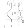
- Fig. 7(a) the additive torque is shown by a solid line, the engine torque by a dashed line, and the motor torque by a dashed line.
- Fig. 7(b) the target slip is shown by a solid line, the high torque slip ratio by a dashed line, and the low torque slip ratio by a dashed line.
- control device 30 sets the target slip ratio to the low torque slip ratio. Then, from time t1, the driver depresses the accelerator pedal of vehicle 1. In this case, control device 30 first increases the engine torque from time t1 in response to the driver's request. As a result, the added torque increases from time t1.
- control device 30 gradually changes the target slip ratio from the low torque slip ratio to the high torque slip ratio at a predetermined rate (see the area surrounded by a circle marked with the symbol A in Figure 7).
- time t2' can be, for example, the time when the added torque reaches threshold value TQth', which is a predetermined amount smaller than threshold value TQth.
- control device 30 sets the target slip ratio to the high torque slip ratio.
- the control device 30 may gradually change the target slip ratio from the high torque slip ratio to the low torque slip ratio at a predetermined rate, for example, from time t3 when the added torque reaches the threshold value TQth (see the area circled with the symbol B in FIG. 7).
- the lock-up clutch 134 generates heat when slipped, but it is undesirable for the lock-up clutch 134 to become too hot. Therefore, the control device 30 may set the target slip ratio to a heat generation protection slip ratio (third slip ratio) when the estimated amount of heat generation of the lock-up clutch 134 is equal to or greater than a predetermined value Qth.
- the predetermined value Qth is set in advance in the control device 30 by, for example, the manufacturer of the vehicle 1.
- the estimated heat generation amount is an estimate of the heat generation amount of the lock-up clutch 134 that is estimated (e.g., calculated) based on, for example, the current added torque and slip ratio.
- the control device 30 calculates the estimated heat generation amount from the current added torque and slip ratio using a predetermined calculation formula. This calculation formula is set in advance in the control device 30 by, for example, the manufacturer of the vehicle 1.
- the control device 30 may also derive the estimated heat generation amount from the current added torque and slip ratio using a predetermined map instead of the calculation formula.
- the heat generation protection slip ratio is a slip ratio that tightens the lock-up clutch 134 more firmly than the high torque slip ratio or the low torque slip ratio. As a result, when the heat generation protection slip ratio is set as the target slip ratio, it is possible to reduce the amount of heat generated by the lock-up clutch 134 compared to when the high torque slip ratio or the low torque slip ratio is set.
- control device 30 has a slip ratio map for heat generation protection Mp3, as shown in FIG. 8, in addition to the high torque slip ratio map Mp1 and the low torque slip ratio map Mp2.
- the slip ratio map for heat generation protection Mp3 is a map (information) that specifies the reference slip ratio that is the reference value for the target slip ratio to be set for each combination of the added torque (i.e., the input torque to the lock-up clutch 134) and the main shaft rotation speed.
- the reference slip ratio corresponding to the combination of the additional torque TQ10 [Nm] and the main shaft rotation speed N10 [rpm] is specified as SL10 [%] in the heat generation protection slip ratio map Mp3.
- Each reference slip ratio specified by the heat generation protection slip ratio map Mp3 is set so that the amount of heat generated per unit time by the lock-up clutch 134 is equal to or less than a predetermined value.
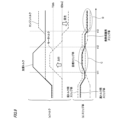
- FIG. 9(a) the added torque is shown in a solid line, the engine torque in a dashed line, and the motor torque in a dashed line.
- FIG. 9(b) the target slip is shown in a solid line, the high torque slip ratio in a dashed line, the low torque slip ratio in a dashed line, and the heat generation protection slip ratio in a dashed double-dashed line. Note that the following explanation will focus on the differences from the example in FIG. 7, and explanations of the same parts as in the example in FIG. 7 will be omitted or simplified as appropriate.
- the estimated heat generation amount is equal to or greater than the predetermined value Qth during the period from time t11 to time t12 and during the period after time t13.
- the control device 30 sets the target slip ratio to the heat generation protection slip ratio during the relevant period, as shown by the circles marked with the symbols C and D in FIG. 9.
- the control device 30 may set the target slip ratio to the heat generation protection slip ratio, thereby tightening the degree of engagement of the lock-up clutch 134 and reducing the amount of heat generated by the lock-up clutch 134. In this way, it is possible to prevent the lock-up clutch 134 from becoming too hot. Furthermore, by the control device 30 estimating the estimated amount of heat generated based on the current added torque and slip ratio, it is possible to obtain the estimated amount of heat generated without providing a temperature sensor or the like that detects the temperature of the lock-up clutch 134.
- the heat generation protection slip ratio map Mp3 is referenced to derive a target slip ratio based on the added torque and the main shaft rotation speed, making it possible to control the lock-up clutch 134 with an appropriate target slip ratio that takes into account the damping characteristics of the first damper 136a and the second damper 136b while keeping the processing burden on the control device 30 low and with a simple configuration.
- the control device 30 may be configured to limit cylinder deactivation, which may increase torque pulsation of the engine 11. This makes it possible to prevent the NV characteristics of the vehicle 1 from deteriorating, even if the degree of engagement of the lock-up clutch 134 is increased due to an increase in the amount of heat generated by the lock-up clutch 134.
- the lock-up damper 136 may deform, for example, as indicated by the dashed line 300 in FIG. 3, and a part of the circumferentially outer surface may come into contact with the wall portion 200.
- the lock-up damper 136 comes into contact with the wall portion 200 in this way, the deformation of the lock-up damper 136 is restricted by the wall portion 200, so that the hysteresis torque of the lock-up damper 136 increases and the damping performance of the lock-up damper 136 decreases.
- the control device 30 may be configured to be able to correct the target slip ratio according to the magnitude of the motor torque, which may be a factor in increasing the added torque to a certain extent. In this way, it becomes possible to control the lock-up clutch 134 with an appropriate target slip ratio that takes into account the decrease in damping performance caused by the lock-up damper 136 (i.e., the first damper 136a and/or the second damper 136b) coming into contact with the wall portion 200.
- the lock-up damper 136 i.e., the first damper 136a and/or the second damper 136b
- the control device 30 refers to a slip ratio correction amount map Mp4 shown in FIG. 10 to derive a correction amount for the target slip ratio based on the motor torque at that time, and executes a correction process to correct the target slip ratio using the correction amount.
- the slip ratio correction amount map Mp4 is a map (information) that specifies the amount of slip ratio correction for each motor torque.
- the slip ratio correction amount map Mp4 specifies that the correction amount for the target slip ratio when the motor torque is -X [Nm] (where -X ⁇ 0) is - ⁇ [%] (where - ⁇ 0). Therefore, when the motor torque is -X [Nm], the control device 30 may set the target slip ratio in the correction process to the reference slip ratio specified in the slip ratio maps Mp1 and Mp2 minus the correction amount ⁇ [%].
- the slip ratio correction amount map Mp4 specifies that the correction amount of the target slip ratio when the motor torque is +X [Nm] (where +X>0) is + ⁇ [%] (where + ⁇ >0). Therefore, when the motor torque is +X [Nm], the control device 30 may set the target slip ratio as the sum of the reference slip ratio specified in the slip ratio maps Mp1 and Mp2 and the correction amount ⁇ [%] in the correction process.
- control device 30 repeatedly executes the series of processes shown in Fig. 11 at a predetermined cycle, for example, while the vehicle 1 is running (for example, while the ignition power is on).
- the control device 30 first determines whether the added torque obtained by adding the engine torque and the motor torque is equal to or greater than the threshold value TQth (step S1). If the control device 30 determines that the added torque is equal to or greater than the threshold value TQth (step S1: YES), the control device 30 refers to the high torque slip ratio map Mp1 shown in FIG. 5 and selects a reference slip ratio corresponding to the combination of the current engine torque and main shaft rotation speed (step S2). On the other hand, if the control device 30 determines that the added torque is less than the boundary torque TQth (step S1: NO), the control device 30 refers to the low torque slip ratio map Mp2 shown in FIG. 6 and selects a reference slip ratio corresponding to the combination of the current engine torque and main shaft rotation speed (step S3).
- control device 30 calculates the estimated heat generation amount when the slip ratio of the lock-up clutch 134 is the reference slip ratio selected in step S2 or step S3 based on the current added torque (step S4). The control device 30 then determines whether the estimated heat generation amount is equal to or greater than a predetermined value Qth (step S5). If it is determined that the estimated heat generation amount is not equal to or greater than the predetermined value Qth (step S5: NO), the control device 30 proceeds directly to the processing of step S8.
- step S5 YES
- the control device 30 refers to the heat generation protection slip ratio map Mp3 shown in FIG. 8 and reselects the reference slip ratio corresponding to the combination of the current added torque and main shaft rotation speed (step S6).
- the control device 30 then turns ON the cylinder deactivation operation prohibition flag, which is a flag that restricts the cylinder deactivation operation of the engine 11 (step S7), and proceeds to the processing of step S8.
- control device 30 refers to the slip ratio correction amount map Mp4, and sets the reference slip ratio selected in step S2, step S3, or step S6 corrected by the correction amount corresponding to the motor torque as the target slip ratio (step S8). Then, the control device 30 controls the lock-up clutch 134 so that the actual slip ratio becomes the set target slip (step S9), and ends the series of processes shown in FIG. 5.
- the target slip ratio when the engine torque is a predetermined value is made different between when the added torque obtained by adding the engine torque and the motor torque is equal to or greater than a threshold value (e.g., boundary torque TQth) and when the added torque is less than the threshold value.
- a threshold value e.g., boundary torque TQth
- the lock-up clutch 134 can be set to an appropriate slip ratio, making it possible to improve energy efficiency while avoiding deterioration of the NV characteristics of the vehicle 1.
- the vehicle 1 is described in which the motor generator 12 is disposed in front of the torque converter 13, but this is not limited thereto.
- the vehicle 1 may be one in which the motor generator 12 is disposed in the rear of the torque converter 13.
- the control device 30 changes the target slip ratio depending on whether the added torque acting on the lockup damper 136 is equal to or greater than a threshold value (boundary torque TQth), thereby making it possible to control the lockup clutch 134 with an appropriate target slip ratio in consideration of the characteristics of the lockup damper 136 having a dual damper structure.
- a threshold value boundary torque TQth
- the control device 30 may derive the target slip ratio using the high torque slip ratio map Mp1 shown in FIG. 5 or the low torque slip ratio map Mp2 shown in FIG. 6 only when the engine 11 is in all-cylinder operation.
- the control device 30 may derive the target slip ratio using a slip ratio map for cylinder deactivation operation different from the high torque slip ratio map Mp1 and the low torque slip ratio map Mp2.
- the control device 30 may keep the target slip ratio constant when the engine torque is a predetermined value regardless of the magnitude of the added torque.
- the control device 30 may also derive the target slip ratio using the high torque slip ratio map Mp1 or the low torque slip ratio map Mp2, as described above, whether the engine 11 is in all-cylinder operation or in cut-off cylinder operation.
- a high torque slip ratio map different from the high torque slip ratio map Mp1 (hereinafter also referred to as a high torque slip ratio map during cylinder deactivation) may be provided, and a low torque slip ratio map different from the low torque slip ratio map Mp2 (hereinafter also referred to as a low torque slip ratio map during cylinder deactivation) may be provided.
- the control device 30 may derive the target slip ratio using the high torque slip ratio map Mp1 or the low torque slip ratio map Mp2, while when the engine 11 is in cylinder deactivation operation, the control device 30 may derive the target slip ratio using the high torque slip ratio map during cylinder deactivation or the low torque slip ratio map during cylinder deactivation.
- control device 30 derives the target slip ratio using maps such as the slip ratio maps Mp1 and Mp2, but this is not limited to the above.
- control device 30 may derive the target slip ratio using a predetermined calculation formula prepared in advance instead of a map.
- control device 30 refers to the slip ratio correction amount map Mp4 shown in FIG. 10 and corrects the target slip ratio according to the motor torque, but this is not limited to the above.
- a three-axis slip ratio map consisting of engine torque, main shaft speed, and motor torque may be referenced to derive a target slip ratio that takes into account the decrease in damping performance caused by the lock-up damper 136 coming into contact with the wall portion 200.
- control device 30 calculates the estimated heat generation amount when the slip ratio of the lockup clutch 134 is set to the reference slip ratio selected in step S2 or step S3, but this is not limited to the above.
- the control device 30 may calculate the estimated heat generation amount from the heat generation amount of the lockup clutch 134 based on the most recent slip ratio.
- the heat generation amount of the lockup clutch 134 based on the most recent slip ratio may be used as the estimated heat generation amount.
- a control device that controls an engagement state of a disconnection device (lock-up clutch 134) provided on a transmission path that transmits the torque of a first drive source (engine 11) having torque pulsation and the torque of a second drive source (motor generator 12) to drive wheels (drive wheels DW),
- the transmission path further includes a first elastic member (first damper 136a) and a second elastic member (second damper 136b) that have different damping characteristics and are connected in series
- the control device includes: The slip ratio of the disconnecting device is controllable based on a target slip ratio according to the torque of the first drive source, the target slip ratio when the torque of the first drive source is a predetermined value is made different between a case where an added torque obtained by adding the torque of the first drive source and the torque of the second drive source is equal to or greater than a threshold value and a case where the added torque is less than the threshold value; Control device.
- the target slip ratio when the torque of the first drive source is a predetermined value is made different between when the torque obtained by adding the torque of the first drive source and the torque of the second drive source is equal to or greater than a threshold value and when it is less than the threshold value.
- the target slip ratio is made different according to the torque of the second drive source.
- the first elastic member is configured to act in a first torque range equal to or greater than a predetermined boundary torque (boundary torque TQth), the second elastic member is configured to act in a second torque range less than the boundary torque;
- the threshold value is set based on the boundary torque.
- the control device includes: deriving the target slip ratio based on the torque of the first drive source by referring to a slip ratio map that defines a reference value of the target slip ratio to be set for each torque; switching the slip ratio map to be referred to depending on whether the added torque is equal to or greater than the threshold value or whether the added torque is less than the threshold value; Control device.
- the control device includes: When the torque of the first drive source is the predetermined value and the additional torque is equal to or greater than the threshold value, the target slip ratio is set to a first slip ratio; When the torque of the first drive source is the predetermined value and the additional torque is less than the threshold value, the target slip ratio is set to a second slip ratio; The first slip ratio is a slip ratio that weakens the degree of fastening of the disconnecting device compared to the second slip ratio. Control device.
- the control device includes: When changing the target slip ratio from one of the first slip ratio and the second slip ratio to the other in response to the additional torque, the target slip ratio is changed gradually at a predetermined rate. Control device.
- the control device includes: The device is configured to be capable of acquiring an estimated heat generation amount, which is an estimated value of the heat generation amount of the disconnecting device; When the estimated heat generation amount is equal to or greater than a predetermined value when the target slip ratio is the first slip ratio or the second slip ratio, the target slip ratio is set to a third slip ratio; The third slip ratio is a slip ratio that strengthens the degree of fastening of the disconnecting device compared to the first slip ratio or the second slip ratio. Control device.
- the degree of fastening of the disconnecting device can be increased to reduce the amount of heat generated by the disconnecting device, thereby making it possible to prevent the disconnecting device from becoming too hot.
- the control device includes: When the estimated heat generation amount when the target slip ratio is the first slip ratio or the second slip ratio is equal to or greater than the predetermined value, the cylinder cut-off operation of the internal combustion engine is further limited. Control device.
- the control device obtains the estimated heat generation amount by estimating the estimated heat generation amount based on a current added torque. Control device.
- the control device according to any one of (1) to (8), the first elastic member and the second elastic member are provided along a circumferential direction of a rotation shaft that is rotated by a torque of the first driving source and a torque of the second driving source, a wall portion (wall portion 200) of a holding member that holds the first elastic member and the second elastic member is provided at least on the circumferential outer side of the first elastic member and the second elastic member,
- the control device is further configured to be capable of correcting the target slip ratio in accordance with a torque of the second drive source. Control device.
- the added torque becomes large to a certain extent, at least a part of the circumferential outer side of the first elastic member and the second elastic member connected in series may come into contact with the wall portion of the retaining member.
- the first elastic member or the second elastic member is in contact with the wall portion in this manner, the deformation of the first elastic member or the second elastic member is restricted by the wall portion, and the damping performance of the first elastic member or the second elastic member decreases.
- the target slip ratio can be corrected according to the torque of the second drive source, it is possible to control the disconnecting device with an appropriate target slip ratio that takes into account the decrease in damping performance caused by the first elastic member or the second elastic member coming into contact with the wall portion.
- Vehicle 11 (first drive source) 12 Motor generator (second drive source) 30 Control device 134 Lock-up clutch (disconnecting device) 136a: first damper (first elastic member) 136b Second damper (second elastic member) 200 Wall DW Drive wheel TQth Boundary torque
Landscapes
- Engineering & Computer Science (AREA)
- General Engineering & Computer Science (AREA)
- Mechanical Engineering (AREA)
- Physics & Mathematics (AREA)
- Fluid Mechanics (AREA)
- Control Of Fluid Gearings (AREA)
Abstract
トルク脈動のあるエンジン(11)のトルクと、モータジェネレータ(12)のトルクとを駆動輪(DW)に伝達する伝達経路上には、減衰特性が互いに異なり且つ直列に接続された第1ダンパ(136a)と第2ダンパ(136b)とを有するロックアップクラッチ(134)が設けられる。制御装置は、エンジン(11)のトルクに応じた目標スリップ率に基づき、ロックアップクラッチ(134)のスリップ率を制御可能に構成され、エンジン(11)のトルクとモータジェネレータ(12)のトルクとを加算した加算トルクが閾値以上の場合と、加算トルクが閾値未満の場合とで、エンジン(11)のトルクが所定値であるときの目標スリップ率を互いに異ならせる。
Description
本発明は、制御装置に関する。
近年、地球の気候変動に対する具体的な対策として、低炭素社会又は脱炭素社会の実現に向けた取り組みが活発化している。自動車等の車両においても、CO2排出量の削減やエネルギー効率の向上が要求され、駆動源の電動化が進んでいる。
また、従来から、例えば、内燃機関等の駆動源のトルクを駆動輪に伝達する伝達経路上に断接装置(例えばロックアップクラッチ)を備える車両もある。一例として、下記特許文献1には、締結量を制御可能なロックアップ機構を備えたトルクコンバータを、前後の車輪の一方とエンジンとの間に介設させた前後輪駆動車両の制御装置が、当該前後輪駆動車両の運転状態に応じて設定された目標スリップ量となるようにロックアップ機構を制御するロックアップ制御手段と、モータの駆動力を設定するモータ駆動力設定手段と、モータ駆動力設定手段により設定されたモータの駆動力に応じて目標スリップ量を補正する補正手段とを備えるようにした技術が開示されている。
しかしながら、従来技術にあっては、トルク脈動のある第1駆動源のトルクと、第2駆動源のトルクとを駆動輪に伝達する伝達経路上に設けられた断接装置のスリップ率を適切に制御する観点から、改善の余地があった。例えば、従来技術にあっては、上記伝達経路に、減衰特性が互いに異なり且つ直列に接続された第1弾性部材と第2弾性部材とが設けられている場合に、断接装置のスリップ率を適切に制御することが難しく、不適切なスリップ率としてしまうことによって第1駆動源のトルク脈動が駆動輪に伝達されて、NV(Noise,Vibration)特性が悪化したりするおそれもあった。
本発明は、トルク脈動のある第1駆動源のトルクと、第2駆動源のトルクとを駆動輪に伝達する伝達経路上に設けられた断接装置のスリップ率を適切に制御することを可能にする制御装置を提供する。そして、延いてはエネルギー効率の改善に寄与するものである。
本発明の一態様は、
トルク脈動のある第1駆動源のトルクと、第2駆動源のトルクとを駆動輪に伝達する伝達経路上に設けられた断接装置の締結状態を制御する制御装置であって、
前記伝達経路には、減衰特性が互いに異なり且つ直列に接続された第1弾性部材と第2弾性部材とがさらに設けられ、
前記制御装置は、
前記第1駆動源のトルクに応じた目標スリップ率に基づき、前記断接装置のスリップ率を制御可能に構成され、
前記第1駆動源のトルクと前記第2駆動源のトルクとを加算した加算トルクが閾値以上の場合と、前記加算トルクが前記閾値未満の場合とで、前記第1駆動源のトルクが所定値であるときの前記目標スリップ率を互いに異ならせる、
制御装置である。
トルク脈動のある第1駆動源のトルクと、第2駆動源のトルクとを駆動輪に伝達する伝達経路上に設けられた断接装置の締結状態を制御する制御装置であって、
前記伝達経路には、減衰特性が互いに異なり且つ直列に接続された第1弾性部材と第2弾性部材とがさらに設けられ、
前記制御装置は、
前記第1駆動源のトルクに応じた目標スリップ率に基づき、前記断接装置のスリップ率を制御可能に構成され、
前記第1駆動源のトルクと前記第2駆動源のトルクとを加算した加算トルクが閾値以上の場合と、前記加算トルクが前記閾値未満の場合とで、前記第1駆動源のトルクが所定値であるときの前記目標スリップ率を互いに異ならせる、
制御装置である。
本発明によれば、トルク脈動のある第1駆動源のトルクと、第2駆動源のトルクとを駆動輪に伝達する伝達経路上に設けられた断接装置のスリップ率を適切に制御することを可能にし、延いてはエネルギー効率の改善に寄与し得る制御装置を提供できる。
以下、本発明の制御装置の一実施形態を、図面を参照しながら詳細に説明する。なお、図面は、符号の向きに見るものとする。また、以下では、同一又は類似の要素には同一又は類似の符号を付して、その説明を適宜省略又は簡略化することがある。
[車両]
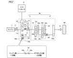
図1に示すように、本実施形態における車両1は、いわゆるハイブリッド電気自動車(Hybrid Electrical Vehicle)であり、本発明における第1駆動源の一例であるエンジン11と、本発明における第2駆動源の一例であるモータジェネレータ12と、駆動輪DWと、エンジン11及びモータジェネレータ12のトルクを駆動輪DWに伝達する動力伝達経路の少なくとも一部を構成する変速機TMと、バッテリ20と、電力変換装置21と、車両1全体の制御を司る制御装置30と、を備える。制御装置30は、本発明の制御装置の一例である。なお、図1において、太実線は機械連結を示し、二重破線は電気配線を示し、実線矢印は制御信号又は検出信号を示している。
図1に示すように、本実施形態における車両1は、いわゆるハイブリッド電気自動車(Hybrid Electrical Vehicle)であり、本発明における第1駆動源の一例であるエンジン11と、本発明における第2駆動源の一例であるモータジェネレータ12と、駆動輪DWと、エンジン11及びモータジェネレータ12のトルクを駆動輪DWに伝達する動力伝達経路の少なくとも一部を構成する変速機TMと、バッテリ20と、電力変換装置21と、車両1全体の制御を司る制御装置30と、を備える。制御装置30は、本発明の制御装置の一例である。なお、図1において、太実線は機械連結を示し、二重破線は電気配線を示し、実線矢印は制御信号又は検出信号を示している。
エンジン11は、全ての気筒を稼働させる全筒運転と、一部の気筒を休止させた状態で運転する休筒運転とを切替可能に構成された内燃機関である。より具体的には、エンジン11は、インジェクタ(不図示)により供給された燃料(例えばガソリン)を燃焼させることによって発生した機械エネルギー(動力)を、クランクシャフト11a(図2を参照)を回転駆動することによって出力する。エンジン11から出力されたトルク(動力)は、エンジン11と機械的に連結された変速機TMを介して駆動輪DWに伝達され、車両1の走行に供される。
また、エンジン11は、モータジェネレータ12とも機械的に連結されている。モータジェネレータ12は、例えば三相の交流モータであり、電力が供給されることによってトルク(動力)を出力する電動機として機能する。より具体的には、モータジェネレータ12のロータ(不図示)は、エンジン11のクランクシャフト11aと連結されている。このため、エンジン11及びモータジェネレータ12からなるパワープラントから出力されるパワープラントトルクのクランクシャフト11aの軸端でのトルク(以下、クランク端トルクともいう)は、エンジン11から出力されるトルク(以下、エンジントルクともいう)と、モータジェネレータ12から出力されるトルク(以下、モータトルクともいう)との和となる。すなわち、クランク端トルクは、エンジントルクとモータトルクとを加算した加算トルク(以下、単に、加算トルクともいう)となっている。
エンジン11とモータジェネレータ12とが機械的に連結されていることで、車両1では、エンジン11による駆動輪DWの駆動(すなわち車両1の走行)を、モータジェネレータ12によって補助するモータアシストが可能となっている。
また、エンジン11とモータジェネレータ12とが機械的に連結されていることで、エンジン11によってモータジェネレータ12を回転駆動したり、モータジェネレータ12によってエンジン11を回転駆動したりすることも可能である。例えば、車両1では、モータジェネレータ12によるクランキングによってエンジン11を始動させることが可能になっている。
モータジェネレータ12は、電力変換装置21を介して、バッテリ20と電気的に接続されている。バッテリ20は、例えば、直列に接続された複数の蓄電セルを有し、所定の電圧(例えば50~200[V])を出力可能に構成されたバッテリである。バッテリ20の蓄電セルとしては、例えば、リチウムイオン電池やニッケル水素電池を用いることができる。
電力変換装置21は、インバータやDC/DCコンバータ(いずれも不図示)等を備えて構成され、制御装置30の制御に従って電力の変換を行う装置である。例えば、電力変換装置21は、バッテリ20から供給された直流電力を三相の交流電力に変換してモータジェネレータ12に供給したり、モータジェネレータ12から供給された三相の交流電力を直流電力に変換してバッテリ20に供給したりする。モータジェネレータ12は、電力変換装置21を介してバッテリ20の電力が供給されることで、前述のモータアシストを行うことが可能である。
また、モータジェネレータ12は、回転駆動されることによって発電を行う発電機としても機能する。モータジェネレータ12は、前述したようにエンジン11によって回転駆動され得るほか、車両1の制動等に伴う駆動輪DW側からの入力によっても回転駆動され得る。モータジェネレータ12によって発電された電力は、電力変換装置21を介してバッテリ20に供給され、バッテリ20の充電に供される。
変速機TMは、例えば、複数の変速段(例えば7段)を有する多段式変速機であり、エンジン11及びモータジェネレータ12から駆動輪DWまでの動力伝達経路に設けられる。より具体的には、変速機TMは、図2に示すように、トルクコンバータ13と、ギヤボックス14と、を含んで構成される。
トルクコンバータ13は、ポンプインペラ131と、タービンランナ132と、ステータ133と、ロックアップクラッチ134と、を備える。ポンプインペラ131は、エンジン11及びモータジェネレータ12(具体的にはクランクシャフト11a)と機械的に連結され、これらの回転駆動に伴って一体回転する。タービンランナ132は、ポンプインペラ131の作動油吐出口に近接して配置される作動油流入口を有するとともに、ギヤボックス14の入力軸であるメインシャフト141と機械的に連結され、メインシャフト141と一体回転する。ステータ133は、タービンランナ132とポンプインペラ131との間に挟まれるように配置され、タービンランナ132からポンプインペラ131に戻る作動油の流れを偏向する。また、ステータ133は、ワンウェイクラッチ135を介してトルクコンバータ13のハウジング(不図示)等に支持されている。トルクコンバータ13は、ポンプインペラ131とタービンランナ132との間に形成された循環路に作動油を循環させることにより、作動油を介してポンプインペラ131からタービンランナ132に動力(回転動力)を伝達できる。
ロックアップクラッチ134は、本発明における断接装置の一例であり、エンジン11(具体的にはクランクシャフト11a)とメインシャフト141との機械的な接続を断接可能なクラッチである。ロックアップクラッチ134を締結することで、エンジントルクを、ロックアップクラッチ134を介してメインシャフト141に伝達することが可能になる。例えば、ロックアップクラッチ134が完全に締結されたとき(換言すると、後述のスリップ率が100[%]とされたとき)、メインシャフト141は、クランクシャフト11aの回転に合わせて同様に回転する。その一方で、ロックアップクラッチ134は、スリップすることにより、クランクシャフト11aの回転動力を減衰してメインシャフト141に伝達することもできる。
また、ロックアップクラッチ134は、図2に示すように、ロックアップダンパ136を有する。ロックアップダンパ136は、ロックアップクラッチ134の締結時(換言すると、後述のスリップ率が0[%]よりも大きいとき)に、駆動輪DW側へ伝達されるエンジン11のトルク脈動(トルク変動)を減衰するための弾性部材(ダンパ)である。
本実施形態では、図2に示すように、ロックアップダンパ136は、減衰特性が互いに異なり且つ直列に接続された第1ダンパ136aと第2ダンパ136bとを有する、いわゆる2重ダンパ構造となっている。そして、ロックアップクラッチ134(すなわち変速機TM)への入力トルクとなる加算トルクが所定の境界トルクTQth以上となる高トルク範囲(第1トルク範囲)では第1ダンパ136a及び第2ダンパ136bのうちの第1ダンパ136aが、加算トルクが境界トルクTQth未満となる低トルク範囲(第2トルク範囲)では第1ダンパ136a及び第2ダンパ136bのうちの第2ダンパ136bが、それぞれ作用するように、ロックアップダンパ136は構成されている。このようなロックアップダンパ136により、加算トルクが高トルク範囲及び低トルク範囲のいずれとなった場合にも、駆動輪DWへ伝達されるエンジン11のトルク脈動を効果的に減衰することが可能となる。
第1ダンパ136a及び第2ダンパ136bは、例えば、ピッチがそれぞれ異なる二種類のスプリングを連結したものであってもよいし、不等ピッチスプリングとして一体形成されたものであってもよい。なお、第1ダンパ136aは本発明における第1弾性部材の一例であり、第2ダンパ136bは本発明における第2弾性部材の一例である。
また、第1ダンパ136a及び第2ダンパ136bは、図3に示すように、エンジントルク及び/又はモータトルク(すなわち加算トルク)によって回転されるクランクシャフト11aやメインシャフト141の周方向に沿って設けられる。そして、第1ダンパ136a及び第2ダンパ136bの周方向外側には、第1ダンパ136a及び第2ダンパ136bを保持する保持部材(例えばトルクコンバータ13のハウジング)の壁部200が設けられる。
図2に戻り、ギヤボックス14は、エンジン11やモータジェネレータ12の出力がトルクコンバータ13及びロックアップクラッチ134の少なくとも一方を介して伝達されるメインシャフト141と、メインシャフト141に伝達された動力を変速可能な複数の変速機構142,143と、これら複数の変速機構のうちのいずれかの変速機構により変速された動力を駆動輪DW側へ出力する出力ギヤ144aを含む出力部材144と、を備える。
ギヤボックス14が備える複数の変速機構は、第1変速機構142と、第2変速機構143とを含む。第1変速機構142は、第1変速クラッチ142aと、第1変速クラッチ142aが締結されることでメインシャフト141と一体回転する第1ドライブギヤ142bと、出力部材144と一体回転する第1ドリブンギヤ142cと、を備える。第2変速機構143は、第2変速クラッチ143aと、第2変速クラッチ143aが締結されることでメインシャフト141と一体回転する第2ドライブギヤ143bと、出力部材144と一体回転する第2ドリブンギヤ143cと、を備える。
なお、図2には、ギヤボックス14が備える変速機構として、第1変速機構142及び第2変速機構143のみを図示しているが、ギヤボックス14は、例えば、第1変速機構142及び第2変速機構143以外の変速機構(不図示)も備えている。
図1に戻り、制御装置30は、エンジン11、変速機TM、及び電力変換装置21等を制御する装置である。さらに、制御装置30は、電力変換装置21の制御を介して、モータジェネレータ12を制御することもできる。なお、モータジェネレータ12の制御に関し、制御装置30は、モータジェネレータ12を直接制御してもよいし、バッテリ20の入出力を制御してもよい。
制御装置30には各種センサが接続されており、制御装置30は、これら各種センサから受け付けた情報(検出信号)に基づき、エンジン11、変速機TM、及び電力変換装置21(すなわちモータジェネレータ12)等を制御する。
制御装置30に接続されるセンサとしては、例えば、エンジン11(換言するとクランクシャフト11a)の回転数(以下、エンジン回転数ともいう。図2中のNEも参照)を検出するエンジン回転数センサ17、車両1の走行速度(以下、車速ともいう)を検出する車速センサ18、メインシャフト141の回転数(以下、メインシャフト回転数ともいう。図2中のNMも参照)を検出するメインシャフト回転数センサ19(図2を参照)を挙げることができる。
さらに、制御装置30に接続される他のセンサとしては、車両1のアクセルペダルに対する操作量(以下、AP開度ともいう)を検出するAPセンサ、車両1のブレーキペダルに対する操作量を検出するブレーキセンサ、変速機TMの変速段を検出するギヤポジションセンサ、バッテリ20の出力や温度を検出するバッテリセンサ、エンジン11の吸気圧(吸気管圧力)を検出する吸気圧センサ(いずれも不図示)等を挙げることができる。また、制御装置30には、大気圧を検出する大気圧センサ(不図示)が接続されていてもよい。
変速機TMに関する制御の一例として、制御装置30は、例えば、ロックアップクラッチ134、第1変速クラッチ142a、及び第2変速クラッチ143aといった変速機TMが備える各クラッチの締結状態を制御する。
ロックアップクラッチ134の制御において、制御装置30は、エンジントルクに応じた目標スリップ率を設定し、当該目標スリップ率に基づき、ロックアップクラッチ134の実際のスリップ率を制御する。
ここで、スリップ率は、ロックアップクラッチ134の締結度合い(換言するとスリップ量)をあらわす指標値である。本実施形態では、スリップ率を、スリップ率[%]=メインシャフト回転数÷エンジン回転数×100[%]と定義する。すなわち、本実施形態において、スリップ率が100[%]以下の領域では、スリップ率が大きいほど、ロックアップクラッチ134の締結度合いが強い(換言するとスリップが少ない)。
ロックアップクラッチ134の制御において、制御装置30は、例えば、エンジン回転数センサ17及びメインシャフト回転数センサ19の検出結果を参照しながら、ロックアップクラッチ134のスリップ率がそのときのエンジントルクに応じた目標スリップ率となるように、ロックアップクラッチ134を制御する。これにより、エンジントルクに比例して大きくなるエンジン11のトルク脈動に起因したNV特性の悪化を抑制することが可能となる。なお、制御装置30によるスリップ率制御については後で詳述するため、ここでの詳細な説明を省略する。
制御装置30は、例えば、各種演算を行うプロセッサと、各種情報を記憶する記憶媒体(例えばフラッシュメモリ)を有する記憶装置と、制御装置30の内部と外部とのデータの入出力を制御する入出力装置とを含んで構成されるECU(Electronic Control Unit)等によって実現される。また、制御装置30は、1つのECUによって実現されてもよいし、複数のECUが協調動作することによって実現されてもよい。
以上のように構成された車両1は、エンジントルクのみにより走行するエンジン走行と、エンジントルク及びモータトルクにより走行するモータアシスト走行と、及びモータジェネレータ12により回生エネルギーを得つつエンジントルクにより走行する(すなわちエンジントルクと、当該エンジントルクとは逆向きのモータトルクとにより走行する)モータ回生走行と、を行い得る。
ここで、力行時のエンジントルクの向きを正(プラス)とすると、エンジン走行時のモータトルクはゼロとなる。また、モータアシスト走行時のモータトルクは正となる。そして、モータ回生走行時のモータトルクは負(マイナス)となる。このため、エンジン走行、モータアシスト走行、及びモータ回生走行のそれぞれで、エンジントルクが同じであったとしても、変速機TM(例えばロックアップクラッチ134)に入力される加算トルクは異なるものとなる。
例えば、エンジン走行の際には、モータトルクがゼロとなるため、エンジントルクがそのまま加算トルクとして変速機TMに入力される。これに対し、モータアシスト走行の際には、モータトルクが正となるため、エンジントルクよりも大きいトルクが加算トルクとして変速機TMに入力される。また、モータ回生走行の際には、モータトルクが負となるため、エンジントルクよりも小さいトルクが加算トルクとして変速機TMに入力される。
このように、車両1では、エンジントルクが同じであったとしても、モータトルクによっては、加算トルクが高トルク範囲となり第1ダンパ136aが作用したり、反対に加算トルクが低トルク範囲となり第2ダンパ136bが作用したりする。したがって、車両1では、直列に接続された第1ダンパ136a及び第2ダンパ136b(すなわち2重ダンパ構造)を有するロックアップダンパ136の特性を考慮して、ロックアップクラッチ134を適切なスリップ率で制御することが望まれる。
そこで、制御装置30は、エンジントルクとモータトルクとを加算した加算トルクが閾値以上の場合と、加算トルクが閾値未満の場合とで、エンジントルクが所定値であるときの目標スリップ率を互いに異ならせる。換言すると、エンジントルクが同じであったとしても、モータトルクに応じて目標スリップ率を異ならせる。これにより、直列に接続された第1ダンパ136a及び第2ダンパ136b(すなわち2重ダンパ構造)を有するロックアップダンパ136の特性を考慮して、ロックアップクラッチ134を適切な目標スリップ率によって制御することが可能となる。
したがって、例えば、車両1がモータアシスト走行を行うことにより、エンジントルクは比較的小さいものの加算トルクが高トルク範囲となった場合に、ロックアップクラッチ134をスリップさせ過ぎて、車両1の燃費性能が悪化してしまうのを抑制することが可能となる。また、車両1がモータ回生走行を行うことにより、エンジントルクは比較的大きいものの加算トルクが低トルク範囲となった場合に、ロックアップクラッチ134をスリップさせなさ過ぎて、車両1のNV特性が悪化してしまうのを抑制することが可能となる。なお、上記の閾値は、例えば、車両1の製造者等により制御装置30にあらかじめ設定される。
[スリップ率制御]
以下、図4~図7を参照して、制御装置30によるスリップ率制御の一例について、より詳しく説明する。
以下、図4~図7を参照して、制御装置30によるスリップ率制御の一例について、より詳しく説明する。
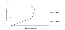
図4には、ロックアップダンパ136の減衰特性が曲線Caで例示されている。なお、図4における縦軸はロックアップクラッチ134への入力トルク(すなわち加算トルク)であり、横軸はクランクシャフト11aに対するメインシャフト141の回転角度の大きさ(すなわち捩り角度)である。
図4に示すように、本実施形態では、ロックアップクラッチ134(すなわち変速機TM)への入力トルクとなる加算トルクが境界トルクTQth以上となる高トルク範囲では第1ダンパ136a及び第2ダンパ136bのうちの第1ダンパ136aが、加算トルクが境界トルクTQth未満となる低トルク範囲では第1ダンパ136a及び第2ダンパ136bのうちの第2ダンパ136bが、それぞれ作用するように、ロックアップダンパ136は構成されている。
制御装置30がスリップ率制御に用いる上記の閾値は、境界トルクTQthに基づき設定される。一例として、上記の閾値は、境界トルクTQthと等しい。これにより、第1ダンパ136a及び第2ダンパ136bのそれぞれが作用するトルク範囲を考慮した適切な目標スリップ率によってロックアップクラッチ134を制御することが可能となる。
本実施形態では、以下、上記の閾値が境界トルクTQthと等しいものとして説明するが、これに限られない。例えば、上記の閾値は、境界トルクTQthを基準とした所定範囲内(例えば境界トルクTQth±1[Nm])に収まるものであれば任意の値としてもよい。また、以下では、境界トルクTQthと等しくした上記の閾値を、閾値TQthともいう。
[スリップ率マップ]
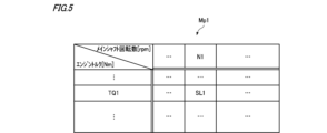
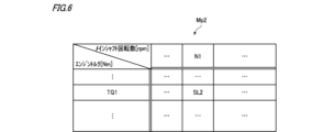
制御装置30は、例えば、図5に例示する高トルク用スリップ率マップMp1、又は図6に例示する低トルク用スリップ率マップMp2を参照して、エンジントルクとメインシャフト回転数とに基づき、目標スリップ率を導出する。
制御装置30は、例えば、図5に例示する高トルク用スリップ率マップMp1、又は図6に例示する低トルク用スリップ率マップMp2を参照して、エンジントルクとメインシャフト回転数とに基づき、目標スリップ率を導出する。
高トルク用スリップ率マップMp1及び低トルク用スリップ率マップMp2は、エンジントルクとメインシャフト回転数との組み合わせごとに、設定すべき目標スリップ率の基準値となる基準スリップ率を規定したマップ(情報)である。
図5の例では、高トルク用スリップ率マップMp1において、エンジントルクがTQ1[Nm]であり、且つメインシャフト回転数がN1[rpm]である組み合わせに対応する基準スリップ率は、SL1[%]と規定されている。また、図6の例では、低トルク用スリップ率マップMp2において、エンジントルクがTQ1[Nm]であり、且つメインシャフト回転数がN1[rpm]である組み合わせに対応する基準スリップ率は、SL2[%](ただしSL2>SL1)と規定されている。
制御装置30は、加算トルクが閾値TQth以上の場合と、加算トルクが閾値TQth未満の場合とで、参照するスリップ率マップMp1、Mp2を切り替える。より具体的には、加算トルクが閾値TQth以上の場合、制御装置30は、高トルク用スリップ率マップMp1を参照して、エンジントルク及びメインシャフト回転数に基づき目標スリップ率を導出する。一方、加算トルクが閾値TQth未満の場合、制御装置30は、低トルク用スリップ率マップMp2を参照して、エンジントルク及びメインシャフト回転数に基づき目標スリップ率を導出する。
したがって、例えば、エンジントルクがTQ1[Nm]であり、且つメインシャフト回転数がN1[rpm]であり、且つ加算トルクが閾値TQth未満の場合、制御装置30は、SL2[%]を目標スリップ率として導出することができる。一方、エンジントルクがTQ1[Nm]であり、且つメインシャフト回転数がN1[rpm]であり、且つ加算トルクが閾値TQth以上の場合、制御装置30は、SL1[%]を目標スリップ率として導出することができる。ここで、SL1[%]は、SL2[%]よりも小さい。
すなわち、エンジントルクがTQ1[Nm]であり、且つメインシャフト回転数がN1[rpm]であるときに、加算トルクが閾値TQth未満の状態から閾値TQth以上になると、制御装置30は、目標スリップ率を、SL2[%]から、SL2[%]よりも小さい(すなわち締結度合いの弱い)SL1[%]に変更することができる。
このように、高トルク用スリップ率マップMp1又は低トルク用スリップ率マップMp2を参照して、エンジントルクとメインシャフト回転数とに基づき目標スリップ率を導出することにより、簡易な構成(例えばできるだけ少ない種類のマップ)で且つ制御装置30の処理負担を抑制しながら、第1ダンパ136a及び第2ダンパ136bの減衰特性を考慮した適切な目標スリップ率によってロックアップクラッチ134を制御することが可能となる。
なお、以下では、高トルク用スリップ率マップMp1を参照して導出される目標スリップ率を、高トルク用スリップ率(第1スリップ率)ともいう。また、低トルク用スリップ率マップMp2を参照して導出される目標スリップ率を、低トルク用スリップ率(第2スリップ率)ともいう。
ところで、目標スリップ率を高トルク用スリップ率と低トルク用スリップ率とのうちの一方から他方へ変更すると、ロックアップクラッチ134のスリップ率が急変して車両1のNV特性が悪化するおそれがある。
そこで、制御装置30は、加算トルクに応じて目標スリップ率を高トルク用スリップ率と低トルク用スリップ率とのうちの一方から他方へ変更する場合に、所定のレートで徐々に変更するようにしてもよい。すなわち、制御装置30は、加算トルクに応じて目標スリップ率を高トルク用スリップ率と低トルク用スリップ率とのうちの一方から他方へ変更する場合に、線形補間しながら徐々に変更するようにしてもよい。このようにすれば、ロックアップクラッチ134のスリップ率が急変するのを抑制でき、この急変の発生によりNV特性が悪化するのを抑制することが可能となる。なお、この場合、上記のレートは、例えば、車両1の製造者等により制御装置30にあらかじめ設定される。
図7(a)には、加算トルクが実線で、エンジントルクが破線で、モータトルクが一点鎖線で、それぞれ示されている。また、図7(b)には、目標スリップが実線で、高トルク用スリップ率が破線で、低トルク用スリップ率が一点鎖線で、それぞれ示されている。
図7の例では、時期t1において、車両1はエンジン走行しており(すなわちモータトルク=0[Nm])、加算トルクが閾値TQth未満であるため、制御装置30は、目標スリップ率を低トルク用スリップ率としている。そして、時期t1から、ドライバー(運転者)が車両1のアクセルペダルを踏み込んだとする。この場合、制御装置30は、ドライバーからの要求に応じて、時期t1から、まずはエンジントルクを増加させていく。これにより、時期t1から、加算トルクが増加する。
その後、制御装置30は、加算トルクが閾値TQthに達する時期t2よりも前の時期t2’から、目標スリップ率を、低トルク用スリップ率から高トルク用スリップ率に向けて所定のレートで徐々に変更する(図7中、符号Aを付した円で囲んだ部分を参照)。ここで、時期t2’は、例えば、閾値TQthより所定量だけ小さい閾値TQth’に加算トルクが達した時期とすることができる。そして、時期t2からは加算トルクが閾値TQth以上であるため、制御装置30は、目標スリップ率を高トルク用スリップ率とする。
また、加算トルクの減少に伴い、目標スリップ率を高トルク用スリップ率から低トルク用スリップ率に変更する場合も同様としてもよい。すなわち、図7に示すように、制御装置30は、例えば、加算トルクが閾値TQthに達した時期t3から、目標スリップ率を、高トルク用スリップ率から低トルク用スリップ率に向けて所定のレートで徐々に変更するようにしてもよい(図7中、符号Bを付した円で囲んだ部分を参照)。
[発熱対策]
ロックアップクラッチ134はスリップさせることにより発熱するが、ロックアップクラッチ134が高温になり過ぎるのは好ましくない。そこで、制御装置30は、ロックアップクラッチ134の推定発熱量が所定値Qth以上となる場合には、目標スリップ率を発熱保護用スリップ率(第3スリップ率)とするようにしてもよい。所定値Qthは、例えば、車両1の製造者等により制御装置30にあらかじめ設定される。
ロックアップクラッチ134はスリップさせることにより発熱するが、ロックアップクラッチ134が高温になり過ぎるのは好ましくない。そこで、制御装置30は、ロックアップクラッチ134の推定発熱量が所定値Qth以上となる場合には、目標スリップ率を発熱保護用スリップ率(第3スリップ率)とするようにしてもよい。所定値Qthは、例えば、車両1の製造者等により制御装置30にあらかじめ設定される。
ここで、推定発熱量は、例えば、現在の加算トルク及びスリップ率に基づき推定(例えば算出)される、ロックアップクラッチ134の発熱量の推定値である。例えば、制御装置30は、所定の計算式を用いて、現在の加算トルク及びスリップ率から推定発熱量を算出する。この計算式は、例えば、車両1の製造者等により制御装置30にあらかじめ設定される。また、制御装置30は、計算式の代わりに所定のマップを用いて、現在の加算トルク及びスリップ率から推定発熱量を導出するようにしてもよい。
発熱保護用スリップ率は、高トルク用スリップ率や低トルク用スリップ率に比べて、ロックアップクラッチ134の締結度合いを強くするスリップ率である。これにより、目標スリップ率を発熱保護用スリップ率とした場合には、高トルク用スリップ率や低トルク用スリップ率とした場合に比べて、ロックアップクラッチ134の発熱量を低減することが可能となる。
例えば、制御装置30は、高トルク用スリップ率マップMp1及び低トルク用スリップ率マップMp2に加えて、図8に例示する発熱保護用スリップ率マップMp3を有する。発熱保護用スリップ率マップMp3は、加算トルク(すなわちロックアップクラッチ134への入力トルク)とメインシャフト回転数との組み合わせごとに、設定すべき目標スリップ率の基準値となる基準スリップ率を規定したマップ(情報)である。
図8の例では、発熱保護用スリップ率マップMp3において、加算トルクがTQ10[Nm]であり、且つメインシャフト回転数がN10[rpm]である組み合わせに対応する基準スリップ率は、SL10[%]と規定されている。発熱保護用スリップ率マップMp3によって規定された各基準スリップ率は、ロックアップクラッチ134の単位時間当たりの発熱量が所定値以下となるように設定されている。
図9(a)には、加算トルクが実線で、エンジントルクが破線で、モータトルクが一点鎖線で、それぞれ示されている。また、図9(b)には、目標スリップが実線で、高トルク用スリップ率が破線で、低トルク用スリップ率が一点鎖線で、発熱保護用スリップ率が二点鎖線で、それぞれ示されている。なお、以下では、図7の例と異なる部分を中心に説明することとし、図7の例と同様の部分についてはその説明を適宜省略又は簡略化する。
図9の例では、時期t11から時期t12までの期間及び時期t13以後の期間において、推定発熱量が所定値Qth以上となっている。このような場合、制御装置30は、図9中、符号C及び符号Dを付した円で囲んだように、当該期間においては目標スリップ率を発熱保護用スリップ率とする。
このように、制御装置30は、ロックアップクラッチ134の発熱量が大きくなると推定される際には、目標スリップ率を発熱保護用スリップ率とすることでロックアップクラッチ134の締結度合いを強くして、ロックアップクラッチ134の発熱量を低減させるようにしてもよい。このようにすれば、ロックアップクラッチ134が高温になるのを抑制することが可能となる。また、制御装置30が、推定発熱量を、現在の加算トルク及びスリップ率に基づき推定することにより、ロックアップクラッチ134の温度を検出する温度センサ等を設けなくても、推定発熱量を取得することが可能となる。
また、推定発熱量が所定値Qth以上となる場合には、発熱保護用スリップ率マップMp3を参照して、加算トルクとメインシャフト回転数とに基づき目標スリップ率を導出することにより、簡易な構成で且つ制御装置30の処理負担を抑制しながら、第1ダンパ136a及び第2ダンパ136bの減衰特性を考慮した適切な目標スリップ率によってロックアップクラッチ134を制御することが可能となる。
さらに、制御装置30は、推定発熱量が所定値Qth以上となる場合には、エンジン11のトルク脈動が大きくなり得る休筒運転を制限するようにしてもよい。これにより、ロックアップクラッチ134の発熱量が大きくなるためにロックアップクラッチ134の締結度合いを強くした場合であっても、車両1のNV特性が悪化するのを抑制することが可能となる。
すなわち、エンジン11の休筒運転時には、全筒運転時に比べて、エンジン11の燃焼行程(爆発行程)で発生するトルク脈動の振幅が大きく且つ周波数が低くなる傾向がある。そこで、制御装置30は、目標スリップ率を発熱保護用スリップ率とすることでロックアップクラッチ134の締結度合いを強くした場合には、休筒運転を制限することで、ロックアップクラッチ134の発熱を抑制しつつ、ドライバーに不快感を与え得るエンジン11のトルク脈動に起因した振動及び騒音の発生を抑制することが可能となる。
ところで、ロックアップクラッチ134に入力される加算トルクがある程度大きくなると、ロックアップダンパ136は、例えば、図3中の符号300で示す破線のように変形して、周方向外側の面の一部が壁部200に接触し得る。このように、ロックアップダンパ136が壁部200に接した状態になると、ロックアップダンパ136の変形が壁部200によって制限されるため、ロックアップダンパ136のヒステリシストルクが増加して、ロックアップダンパ136の減衰性能が低下する。
そこで、制御装置30は、加算トルクがある程度大きくなる要因となり得るモータトルクの大きさに応じて、目標スリップ率を補正可能に構成されてもよい。このようにすれば、ロックアップダンパ136(すなわち第1ダンパ136a及び/又は第2ダンパ136b)が壁部200に接することによる減衰性能の低下を考慮した適切な目標スリップ率によってロックアップクラッチ134を制御することが可能となる。
[目標スリップ率補正]
例えば、制御装置30は、図10に例示するスリップ率補正量マップMp4を参照して、そのときのモータトルクに基づき目標スリップ率の補正量を導出し、当該補正量により目標スリップ率を補正する補正処理を実行する。
例えば、制御装置30は、図10に例示するスリップ率補正量マップMp4を参照して、そのときのモータトルクに基づき目標スリップ率の補正量を導出し、当該補正量により目標スリップ率を補正する補正処理を実行する。
スリップ率補正量マップMp4は、モータトルクごとのスリップ率の補正量を規定したマップ(情報)である。図10の例では、スリップ率補正量マップMp4において、モータトルクが-X[Nm](ただし-X<0)である場合の目標スリップ率の補正量は-α[%](ただし-α<0)と規定されている。したがって、モータトルクが-X[Nm]である場合、制御装置30は、補正処理において、スリップ率マップMp1、Mp2において規定された基準スリップ率から補正量α[%]だけ減算したものを目標スリップ率とすればよい。
また、図10の例では、スリップ率補正量マップMp4において、モータトルクが+X[Nm](ただし+X>0)である場合の目標スリップ率の補正量は+α[%](ただし+α>0)と規定されている。したがって、モータトルクが+X[Nm]である場合、制御装置30は、補正処理において、スリップ率マップMp1、Mp2において規定された基準スリップ率に補正量α[%]だけ加算したものを目標スリップ率とすればよい。
[制御装置が実行する処理の一例]
次に、図11を参照して、制御装置30が実行する処理の一例について説明する。なお、制御装置30は、例えば、車両1の起動中(例えばイグニッション電源がオンである間)、図11に示す一連の処理を所定の周期で繰り返し実行する。
次に、図11を参照して、制御装置30が実行する処理の一例について説明する。なお、制御装置30は、例えば、車両1の起動中(例えばイグニッション電源がオンである間)、図11に示す一連の処理を所定の周期で繰り返し実行する。
図11に示すように、制御装置30は、まず、エンジントルクとモータトルクとを加算した加算トルクが閾値TQth以上であるか否か判断する(ステップS1)。加算した加算トルクが閾値TQth以上であると判断した場合(ステップS1:YES)、制御装置30は、図5に示した高トルク用スリップ率マップMp1を参照して、現在のエンジントルクとメインシャフト回転数との組み合わせに対応する基準スリップ率を選択する(ステップS2)。一方、加算した加算トルクが境界トルクTQth未満であると判断した場合(ステップS1:NO)、制御装置30は、図6に示した低トルク用スリップ率マップMp2を参照して、現在のエンジントルクとメインシャフト回転数との組み合わせに対応する基準スリップ率を選択する(ステップS3)。
次に、制御装置30は、ロックアップクラッチ134のスリップ率を、ステップS2又はステップS3で選択した基準スリップ率とした場合の推定発熱量を、現在の加算トルクに基づき算出する(ステップS4)。そして、制御装置30は、推定発熱量が所定値Qth以上となるか否か判断する(ステップS5)。推定発熱量が所定値Qth以上とならないと判断した場合(ステップS5:NO)、制御装置30は、そのままステップS8の処理へ進む。
一方、推定発熱量が所定値Qth以上となると判断した場合(ステップS5:YES)、制御装置30は、図8に示した発熱保護用スリップ率マップMp3を参照して、現在の加算トルクとメインシャフト回転数との組み合わせに対応する基準スリップ率を再選択する(ステップS6)。そして、制御装置30は、エンジン11の休筒運転を制限するフラグである休筒運転禁止フラグをONして(ステップS7)、ステップS8の処理へ進む。
次に、制御装置30は、スリップ率補正量マップMp4を参照し、ステップS2、ステップS3、又はステップS6で選択した基準スリップ率をモータトルクに応じた補正量だけ補正したものを目標スリップ率として設定する(ステップS8)。そして、制御装置30は、実際のスリップ率が設定した目標スリップとなるようにロックアップクラッチ134を制御して(ステップS9)、図5に示す一連の処理を終了する。
以上に説明したように、本実施形態の制御装置30によれば、エンジントルクとモータトルクとを加算した加算トルクが閾値(例えば境界トルクTQth)以上の場合と、加算トルクが閾値未満の場合とで、エンジントルクが所定値であるときの目標スリップ率を互いに異ならせる。これにより、直列に接続された第1ダンパ136a及び第2ダンパ136b(すなわち2重ダンパ構造)を有するロックアップダンパ136の特性を考慮して、ロックアップクラッチ134を適切な目標スリップ率によって制御することが可能となる。したがって、ロックアップクラッチ134を適切なスリップ率とすることができ、車両1のNV特性の悪化を回避しながら、エネルギー効率を向上させることが可能となる。
以上、本発明の実施形態について説明したが、本発明は上記実施形態に限定されるものではなく、適宜、変形、改良、等が可能である。
例えば、前述した実施形態では、図2に示したように、モータジェネレータ12がトルクコンバータ13の前段に配置された車両1について説明したが、これに限らない。例えば、図12に示すように、車両1は、モータジェネレータ12がトルクコンバータ13の後段に配置されたものであってもよい。この場合も、制御装置30は、ロックアップダンパ136に作用する加算トルクが閾値(境界トルクTQth)以上か否かによって目標スリップ率を変更することにより、2重ダンパ構造を有するロックアップダンパ136の特性を考慮して、ロックアップクラッチ134を適切な目標スリップ率によって制御することが可能となる。ただし、この場合、力行時のエンジントルクの向きを正とすると、力行時のモータトルクは負となる(すなわち前述した実施形態とはモータトルクの正負が反対になる)点に留意されたい。
また、制御装置30は、エンジン11が全筒運転中のときのみ、前述したように、図5に示した高トルク用スリップ率マップMp1又は図6に示した低トルク用スリップ率マップMp2を用いて目標スリップ率を導出するようにしてもよい。一方、制御装置30は、エンジン11が休筒運転中であるときには、高トルク用スリップ率マップMp1及び低トルク用スリップ率マップMp2とは異なる一の休筒運転用のスリップ率マップを用いて目標スリップ率を導出するようにしてもよい。すなわち、制御装置30は、エンジン11が休筒運転中であるときには、エンジントルクが所定値であるときの目標スリップ率を、加算トルクの大きさによらず一定としてもよい。
また、制御装置30は、エンジン11が全筒運転中のときにも休筒運転中のときにも、前述したように、高トルク用スリップ率マップMp1又は低トルク用スリップ率マップMp2を用いて目標スリップ率を導出するようにしてもよい。
また、休筒運転用のスリップ率マップとして、高トルク用スリップ率マップMp1とは異なる他の高トルク用スリップ率マップ(以下、休筒時高トルク用スリップ率マップともいう)を設けるとともに、低トルク用スリップ率マップMp2とは異なる他の低トルク用スリップ率マップ(以下、休筒時低トルク用スリップ率マップともいう)を設けるようにしてもよい。そして、制御装置30は、エンジン11が全筒運転中のときには、高トルク用スリップ率マップMp1又は低トルク用スリップ率マップMp2を用いて目標スリップ率を導出する一方、エンジン11が休筒運転中であるときには、休筒時高トルク用スリップ率マップ又は休筒時低トルク用スリップ率マップを用いて目標スリップ率を導出するようにしてもよい。
また、前述した実施形態では、制御装置30がスリップ率マップMp1、Mp2等のマップを用いて目標スリップ率を導出するようにしたが、これに限られない。例えば、制御装置30は、マップの代わりに、あらかじめ用意された所定の計算式等を用いて目標スリップ率を導出するようにしてもよい。
また、前述した実施形態では、制御装置30は、図10に示したスリップ率補正量マップMp4を参照し、モータトルクに応じて目標スリップ率を補正することとしたが、これに限らない。例えば、エンジントルク、メインシャフト回転数及びモータトルクからなる3軸のスリップ率マップを参照して、ロックアップダンパ136が壁部200に接することによる減衰性能の低下を考慮した目標スリップ率を導出してもよい。
また、前述した実施形態では、制御装置30が、ロックアップクラッチ134のスリップ率を、ステップS2又はステップS3で選択した基準スリップ率とした場合の推定発熱量を算出するようにしたが、これに限られない。例えば、制御装置30は、直近のスリップ率に基づくロックアップクラッチ134の発熱量から、推定発熱量を算出するようにしてもよい。一例として、直近のスリップ率に基づくロックアップクラッチ134の発熱量を、推定発熱量としてもよい。
また、本明細書には少なくとも以下の事項が記載されている。なお、括弧内には、上記した実施形態において対応する構成要素等を示しているが、これに限定されるものではない。
(1) トルク脈動のある第1駆動源(エンジン11)のトルクと、第2駆動源(モータジェネレータ12)のトルクとを駆動輪(駆動輪DW)に伝達する伝達経路上に設けられた断接装置(ロックアップクラッチ134)の締結状態を制御する制御装置(ロックアップクラッチ134)であって、
前記伝達経路には、減衰特性が互いに異なり且つ直列に接続された第1弾性部材(第1ダンパ136a)と第2弾性部材(第2ダンパ136b)とがさらに設けられ、
前記制御装置は、
前記第1駆動源のトルクに応じた目標スリップ率に基づき、前記断接装置のスリップ率を制御可能に構成され、
前記第1駆動源のトルクと前記第2駆動源のトルクとを加算した加算トルクが閾値以上の場合と、前記加算トルクが前記閾値未満の場合とで、前記第1駆動源のトルクが所定値であるときの前記目標スリップ率を互いに異ならせる、
制御装置。
前記伝達経路には、減衰特性が互いに異なり且つ直列に接続された第1弾性部材(第1ダンパ136a)と第2弾性部材(第2ダンパ136b)とがさらに設けられ、
前記制御装置は、
前記第1駆動源のトルクに応じた目標スリップ率に基づき、前記断接装置のスリップ率を制御可能に構成され、
前記第1駆動源のトルクと前記第2駆動源のトルクとを加算した加算トルクが閾値以上の場合と、前記加算トルクが前記閾値未満の場合とで、前記第1駆動源のトルクが所定値であるときの前記目標スリップ率を互いに異ならせる、
制御装置。
(1)によれば、第1駆動源のトルクと第2駆動源のトルクとを加算した加算トルクが閾値以上の場合と閾値未満の場合とで、第1駆動源のトルクが所定値であるときの目標スリップ率を互いに異ならせる。換言すると、第1駆動源のトルクが同じであったとしても、第2駆動源のトルクに応じて目標スリップ率を異ならせる。これにより、直列に接続された第1弾性部材及び第2弾性部材による減衰特性を考慮した適切な目標スリップ率によって断接装置を制御することが可能となる。したがって、断接装置を適切なスリップ率とすることができ、NV(Noise,Vibration)特性の悪化を回避しながら、エネルギー効率を向上させることが可能となる。
(2) (1)に記載の制御装置であって、
前記第1弾性部材は、所定の境界トルク(境界トルクTQth)以上の第1トルク範囲で作用するように構成され、
前記第2弾性部材は、前記境界トルク未満の第2トルク範囲で作用するように構成され、
前記閾値は、前記境界トルクに基づき設定される、
制御装置。
前記第1弾性部材は、所定の境界トルク(境界トルクTQth)以上の第1トルク範囲で作用するように構成され、
前記第2弾性部材は、前記境界トルク未満の第2トルク範囲で作用するように構成され、
前記閾値は、前記境界トルクに基づき設定される、
制御装置。
(2)によれば、第1弾性部材及び第2弾性部材のそれぞれが作用するトルク範囲を考慮した適切な目標スリップ率によって断接装置を制御することが可能となる。
(3) (1)又は(2)に記載の制御装置であって、
前記制御装置は、
トルクごとに設定すべき前記目標スリップ率の基準値を定めたスリップ率マップを参照して、前記第1駆動源のトルクに基づき前記目標スリップ率を導出し、
前記加算トルクが前記閾値以上の場合と、前記加算トルクが前記閾値未満の場合とで、参照する前記スリップ率マップを切り替える、
制御装置。
前記制御装置は、
トルクごとに設定すべき前記目標スリップ率の基準値を定めたスリップ率マップを参照して、前記第1駆動源のトルクに基づき前記目標スリップ率を導出し、
前記加算トルクが前記閾値以上の場合と、前記加算トルクが前記閾値未満の場合とで、参照する前記スリップ率マップを切り替える、
制御装置。
(3)によれば、簡易な構成で且つ制御装置の処理負担の抑制しながら、第1弾性部材及び第2弾性部材の減衰特性を考慮した適切な目標スリップ率によって断接装置を制御することが可能となる。
(4) (1)から(3)のいずれかに記載の制御装置であって、
前記制御装置は、
前記第1駆動源のトルクが前記所定値であり、且つ前記加算トルクが前記閾値以上の場合には、前記目標スリップ率を第1スリップ率とし、
前記第1駆動源のトルクが前記所定値であり、且つ前記加算トルクが前記閾値未満の場合には、前記目標スリップ率を第2スリップ率とし、
前記第1スリップ率は、前記第2スリップ率に比べて、前記断接装置の締結度合いを弱くするスリップ率である、
制御装置。
前記制御装置は、
前記第1駆動源のトルクが前記所定値であり、且つ前記加算トルクが前記閾値以上の場合には、前記目標スリップ率を第1スリップ率とし、
前記第1駆動源のトルクが前記所定値であり、且つ前記加算トルクが前記閾値未満の場合には、前記目標スリップ率を第2スリップ率とし、
前記第1スリップ率は、前記第2スリップ率に比べて、前記断接装置の締結度合いを弱くするスリップ率である、
制御装置。
(4)によれば、加算トルクが閾値以上の場合(換言すると第2駆動源のトルクが大きい場合)には、加算トルクが閾値未満の場合(換言すると第2駆動源のトルクが小さい場合)に比べて、断接装置の締結度合いを弱くすることが可能となる。
(5) (4)に記載の制御装置であって、
前記制御装置は、
前記加算トルクに応じて、前記目標スリップ率を前記第1スリップ率と前記第2スリップ率とのうちの一方から他方へ変更する場合に、所定のレートで徐々に変更する、
制御装置。
前記制御装置は、
前記加算トルクに応じて、前記目標スリップ率を前記第1スリップ率と前記第2スリップ率とのうちの一方から他方へ変更する場合に、所定のレートで徐々に変更する、
制御装置。
(5)によれば、断接装置のスリップ率が急変するのを抑制でき、この急変の発生によりNV特性が悪化するのを抑制することが可能となる。
(6) (4)又は(5)に記載の制御装置であって、
前記制御装置は、
前記断接装置の発熱量の推定値である推定発熱量を取得可能に構成され、
前記目標スリップ率を前記第1スリップ率又は前記第2スリップ率とした場合の前記推定発熱量が所定値以上となる場合には、前記目標スリップ率を第3スリップ率とし、
前記第3スリップ率は、前記第1スリップ率又は前記第2スリップ率に比べて、前記断接装置の締結度合いを強くするスリップ率である、
制御装置。
前記制御装置は、
前記断接装置の発熱量の推定値である推定発熱量を取得可能に構成され、
前記目標スリップ率を前記第1スリップ率又は前記第2スリップ率とした場合の前記推定発熱量が所定値以上となる場合には、前記目標スリップ率を第3スリップ率とし、
前記第3スリップ率は、前記第1スリップ率又は前記第2スリップ率に比べて、前記断接装置の締結度合いを強くするスリップ率である、
制御装置。
(6)によれば、断接装置の発熱量が大きくなると推定される場合には、断接装置の締結度合いを強くすることで断接装置の発熱量を低減して、断接装置が高温になるのを抑制することが可能となる。
(7) (6)に記載の制御装置であって、
前記第1駆動源は、全ての気筒を稼働させる全筒運転と、一部の気筒を休止させた状態で運転する休筒運転とを切替可能に構成された内燃機関(エンジン11)であり、
前記制御装置は、
前記目標スリップ率を前記第1スリップ率又は前記第2スリップ率とした場合の前記推定発熱量が前記所定値以上となる場合には、さらに前記内燃機関の前記休筒運転を制限する、
制御装置。
前記第1駆動源は、全ての気筒を稼働させる全筒運転と、一部の気筒を休止させた状態で運転する休筒運転とを切替可能に構成された内燃機関(エンジン11)であり、
前記制御装置は、
前記目標スリップ率を前記第1スリップ率又は前記第2スリップ率とした場合の前記推定発熱量が前記所定値以上となる場合には、さらに前記内燃機関の前記休筒運転を制限する、
制御装置。
(7)によれば、断接装置の発熱量が大きくなると推定される場合には、第1駆動源としての内燃機関の休筒運転を制限することで、断接装置の締結度合いを強くしても、NV特性が悪化するのを抑制することが可能となる。
(8) (6)又は(7)に記載の制御装置であって、
前記制御装置は、前記推定発熱量を、現在の前記加算トルクに基づき推定することにより取得する、
制御装置。
前記制御装置は、前記推定発熱量を、現在の前記加算トルクに基づき推定することにより取得する、
制御装置。
(8)によれば、断接装置の温度を検出する温度センサを用いることなく、推定発熱量を取得することが可能となる。
(9) (1)から(8)のいずれかに記載の制御装置であって、
前記第1弾性部材及び前記第2弾性部材は、前記第1駆動源のトルク及び前記第2駆動源のトルクによって回転される回転軸の周方向に沿って設けられ、
前記第1弾性部材及び前記第2弾性部材の少なくとも周方向外側には、前記第1弾性部材及び前記第2弾性部材を保持する保持部材の壁部(壁部200)が設けられ、
前記制御装置は、さらに、前記第2駆動源のトルクに応じて、前記目標スリップ率を補正可能に構成される、
制御装置。
前記第1弾性部材及び前記第2弾性部材は、前記第1駆動源のトルク及び前記第2駆動源のトルクによって回転される回転軸の周方向に沿って設けられ、
前記第1弾性部材及び前記第2弾性部材の少なくとも周方向外側には、前記第1弾性部材及び前記第2弾性部材を保持する保持部材の壁部(壁部200)が設けられ、
前記制御装置は、さらに、前記第2駆動源のトルクに応じて、前記目標スリップ率を補正可能に構成される、
制御装置。
(9)によれば、加算トルクがある程度大きくなると、直列に接続された第1弾性部材及び第2弾性部材の周方向外側の少なくとも一部が保持部材の壁部に接し得る。このように第1弾性部材や第2弾性部材が壁部に接した状態であるときには、第1弾性部材や第2弾性部材の変形が壁部によって制限されるため、第1弾性部材や第2弾性部材の減衰性能が低下する。(9)によれば、第2駆動源のトルクに応じて目標スリップ率を補正可能なため、第1弾性部材や第2弾性部材が壁部に接することによる減衰性能の低下を考慮した適切な目標スリップ率で断接装置を制御することが可能となる。
1 車両
11 エンジン(第1駆動源)
12 モータジェネレータ(第2駆動源)
30 制御装置
134 ロックアップクラッチ(断接装置)
136a 第1ダンパ(第1弾性部材)
136b 第2ダンパ(第2弾性部材)
200 壁部
DW 駆動輪
TQth 境界トルク
11 エンジン(第1駆動源)
12 モータジェネレータ(第2駆動源)
30 制御装置
134 ロックアップクラッチ(断接装置)
136a 第1ダンパ(第1弾性部材)
136b 第2ダンパ(第2弾性部材)
200 壁部
DW 駆動輪
TQth 境界トルク
Claims (9)
- トルク脈動のある第1駆動源のトルクと、第2駆動源のトルクとを駆動輪に伝達する伝達経路上に設けられた断接装置の締結状態を制御する制御装置であって、
前記伝達経路には、減衰特性が互いに異なり且つ直列に接続された第1弾性部材と第2弾性部材とがさらに設けられ、
前記制御装置は、
前記第1駆動源のトルクに応じた目標スリップ率に基づき、前記断接装置のスリップ率を制御可能に構成され、
前記第1駆動源のトルクと前記第2駆動源のトルクとを加算した加算トルクが閾値以上の場合と、前記加算トルクが前記閾値未満の場合とで、前記第1駆動源のトルクが所定値であるときの前記目標スリップ率を互いに異ならせる、
制御装置。 - 請求項1に記載の制御装置であって、
前記第1弾性部材は、所定の境界トルク以上の第1トルク範囲で作用するように構成され、
前記第2弾性部材は、前記境界トルク未満の第2トルク範囲で作用するように構成され、
前記閾値は、前記境界トルクに基づき設定される、
制御装置。 - 請求項1又は2に記載の制御装置であって、
前記制御装置は、
トルクごとに設定すべき前記目標スリップ率の基準値を定めたスリップ率マップを参照して、前記第1駆動源のトルクに基づき前記目標スリップ率を導出し、
前記加算トルクが前記閾値以上の場合と、前記加算トルクが前記閾値未満の場合とで、参照する前記スリップ率マップを切り替える、
制御装置。 - 請求項1から3のいずれか1項に記載の制御装置であって、
前記制御装置は、
前記第1駆動源のトルクが前記所定値であり、且つ前記加算トルクが前記閾値以上の場合には、前記目標スリップ率を第1スリップ率とし、
前記第1駆動源のトルクが前記所定値であり、且つ前記加算トルクが前記閾値未満の場合には、前記目標スリップ率を第2スリップ率とし、
前記第1スリップ率は、前記第2スリップ率に比べて、前記断接装置の締結度合いを弱くするスリップ率である、
制御装置。 - 請求項4に記載の制御装置であって、
前記制御装置は、
前記加算トルクに応じて、前記目標スリップ率を前記第1スリップ率と前記第2スリップ率とのうちの一方から他方へ変更する場合に、所定のレートで徐々に変更する、
制御装置。 - 請求項4又は5に記載の制御装置であって、
前記制御装置は、
前記断接装置の発熱量の推定値である推定発熱量を取得可能に構成され、
前記目標スリップ率を前記第1スリップ率又は前記第2スリップ率とした場合の前記推定発熱量が所定値以上となる場合には、前記目標スリップ率を第3スリップ率とし、
前記第3スリップ率は、前記第1スリップ率又は前記第2スリップ率に比べて、前記断接装置の締結度合いを強くするスリップ率である、
制御装置。 - 請求項6に記載の制御装置であって、
前記第1駆動源は、全ての気筒を稼働させる全筒運転と、一部の気筒を休止させた状態で運転する休筒運転とを切替可能に構成された内燃機関であり、
前記制御装置は、
前記目標スリップ率を前記第1スリップ率又は前記第2スリップ率とした場合の前記推定発熱量が前記所定値以上となる場合には、さらに前記内燃機関の前記休筒運転を制限する、
制御装置。 - 請求項6又は7に記載の制御装置であって、
前記制御装置は、前記推定発熱量を、現在の前記加算トルクに基づき推定することにより取得する、
制御装置。 - 請求項1から8のいずれか1項に記載の制御装置であって、
前記第1弾性部材及び前記第2弾性部材は、前記第1駆動源のトルク及び前記第2駆動源のトルクによって回転される回転軸の周方向に沿って設けられ、
前記第1弾性部材及び前記第2弾性部材の少なくとも周方向外側には、前記第1弾性部材及び前記第2弾性部材を保持する保持部材の壁部が設けられ、
前記制御装置は、さらに、前記第2駆動源のトルクに応じて、前記目標スリップ率を補正可能に構成される、
制御装置。
Priority Applications (1)
| Application Number | Priority Date | Filing Date | Title |
|---|---|---|---|
| PCT/JP2023/006455 WO2024176383A1 (ja) | 2023-02-22 | 2023-02-22 | 制御装置 |
Applications Claiming Priority (1)
| Application Number | Priority Date | Filing Date | Title |
|---|---|---|---|
| PCT/JP2023/006455 WO2024176383A1 (ja) | 2023-02-22 | 2023-02-22 | 制御装置 |
Publications (1)
| Publication Number | Publication Date |
|---|---|
| WO2024176383A1 true WO2024176383A1 (ja) | 2024-08-29 |
Family
ID=92500371
Family Applications (1)
| Application Number | Title | Priority Date | Filing Date |
|---|---|---|---|
| PCT/JP2023/006455 Ceased WO2024176383A1 (ja) | 2023-02-22 | 2023-02-22 | 制御装置 |
Country Status (1)
| Country | Link |
|---|---|
| WO (1) | WO2024176383A1 (ja) |
Citations (2)
| Publication number | Priority date | Publication date | Assignee | Title |
|---|---|---|---|---|
| WO2013073394A1 (ja) * | 2011-11-18 | 2013-05-23 | ジヤトコ株式会社 | 自動変速機の制御装置 |
| JP2018155385A (ja) * | 2017-03-21 | 2018-10-04 | トヨタ自動車株式会社 | 車両の制御装置 |
-
2023
- 2023-02-22 WO PCT/JP2023/006455 patent/WO2024176383A1/ja not_active Ceased
Patent Citations (2)
| Publication number | Priority date | Publication date | Assignee | Title |
|---|---|---|---|---|
| WO2013073394A1 (ja) * | 2011-11-18 | 2013-05-23 | ジヤトコ株式会社 | 自動変速機の制御装置 |
| JP2018155385A (ja) * | 2017-03-21 | 2018-10-04 | トヨタ自動車株式会社 | 車両の制御装置 |
Similar Documents
| Publication | Publication Date | Title |
|---|---|---|
| US10023180B2 (en) | Control device and control method for vehicle | |
| JP6500872B2 (ja) | 駆動装置および自動車 | |
| CN110312648B (zh) | 混合动力车辆的动力控制方法及动力控制装置 | |
| US20200298822A1 (en) | Hybrid vehicle | |
| JP2022149909A (ja) | 車両制御装置 | |
| CN110366512B (zh) | 混合动力车辆的动力控制方法及动力控制装置 | |
| CN101379287A (zh) | 用于车辆的控制设备 | |
| CN110325420B (zh) | 混合动力车辆的动力控制方法及动力控制装置 | |
| EP3575164B1 (en) | Driving force control method and device for hybrid vehicle | |
| JP5655693B2 (ja) | ハイブリッド自動車 | |
| WO2024176383A1 (ja) | 制御装置 | |
| JP3876564B2 (ja) | ハイブリッド車両 | |
| US10640118B2 (en) | Method for controlling powertrain of vehicle | |
| EP3575169B1 (en) | Driving force control method and device for hybrid vehicle | |
| EP3575166B1 (en) | Driving force control method and device for hybrid vehicle | |
| JP7725993B2 (ja) | 駆動装置 | |
| JP7703939B2 (ja) | ハイブリッド車 | |
| JP6489510B2 (ja) | ハイブリッド車両の動力制御方法及び動力制御装置 | |
| JP6519958B2 (ja) | ハイブリッド車両の動力制御方法及び動力制御装置 |
Legal Events
| Date | Code | Title | Description |
|---|---|---|---|
| 121 | Ep: the epo has been informed by wipo that ep was designated in this application |
Ref document number: 23924037 Country of ref document: EP Kind code of ref document: A1 |
|
| NENP | Non-entry into the national phase |
Ref country code: DE |
|
| 122 | Ep: pct application non-entry in european phase |
Ref document number: 23924037 Country of ref document: EP Kind code of ref document: A1 |