WO2024176368A1 - 中継装置及び通信制御方法 - Google Patents
中継装置及び通信制御方法 Download PDFInfo
- Publication number
- WO2024176368A1 WO2024176368A1 PCT/JP2023/006312 JP2023006312W WO2024176368A1 WO 2024176368 A1 WO2024176368 A1 WO 2024176368A1 JP 2023006312 W JP2023006312 W JP 2023006312W WO 2024176368 A1 WO2024176368 A1 WO 2024176368A1
- Authority
- WO
- WIPO (PCT)
- Prior art keywords
- ncr
- information
- mac
- base station
- backhaul
- Prior art date
- Legal status (The legal status is an assumption and is not a legal conclusion. Google has not performed a legal analysis and makes no representation as to the accuracy of the status listed.)
- Ceased
Links
Images









Classifications
-
- H—ELECTRICITY
- H04—ELECTRIC COMMUNICATION TECHNIQUE
- H04W—WIRELESS COMMUNICATION NETWORKS
- H04W16/00—Network planning, e.g. coverage or traffic planning tools; Network deployment, e.g. resource partitioning or cells structures
- H04W16/18—Network planning tools
-
- H—ELECTRICITY
- H04—ELECTRIC COMMUNICATION TECHNIQUE
- H04W—WIRELESS COMMUNICATION NETWORKS
- H04W72/00—Local resource management
- H04W72/20—Control channels or signalling for resource management
- H04W72/23—Control channels or signalling for resource management in the downlink direction of a wireless link, i.e. towards a terminal
Definitions
- This disclosure relates to a relay device and a communication control method.
- the 3rd Generation Partnership Project (3GPP (registered trademark)) has developed specifications for the 5th generation mobile communication system (also known as 5G, New Radio (NR) or Next Generation (NG)), and is also working on the next generation, called Beyond 5G, 5G Evolution or 6G.
- 5G New Radio
- NG Next Generation
- a communication device (which may be called a relay device) that relays signals between a user terminal (which may be called UE (User Equipment) or simply a terminal) and a radio base station (which may be simply called a base station) is being considered (see, for example, Non-Patent Document 1).
- UE User Equipment
- a radio base station which may be simply called a base station
- One aspect of the present disclosure provides a relay device and a communication control method that can appropriately relay signals based on instructions for communication-related operations.
- a relay device includes a receiver that receives control information from a base station regarding a beam to be used by the relay device in a communication link for relaying communication between a base station and a terminal with the base station, and a controller that determines a beam to be used by the relay device based on the control information, the control information including one or both of first beam information regarding a first beam to be used for receiving signals from the base station in the communication link, and second beam information regarding a second beam to be used for transmitting signals to the base station in the communication link.
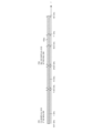
- FIG. 1 is a diagram illustrating an example of a wireless communication system according to an embodiment of the present disclosure.
- FIG. 2 is a diagram illustrating an example of a frequency range used in a wireless communication system according to an embodiment of the present disclosure.
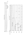
- 1A to 1C are diagrams illustrating example configurations of radio frames, subframes, and slots used in a wireless communication system according to an embodiment of the present disclosure.
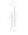
- FIG. 2 is a diagram illustrating an example of the configuration of an NCR.
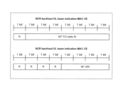
- a diagram showing an example of the configuration of a MAC CE A diagram showing an example of the configuration of a MAC CE.
- a diagram showing an example of the configuration of a MAC CE A diagram showing an example of the configuration of a MAC CE. A diagram showing an example of the configuration of a MAC CE. A diagram showing an example of the configuration of a MAC CE. A diagram showing an example of the configuration of a MAC CE. A diagram showing an example of the configuration of a MAC CE. A diagram showing an example of the configuration of a MAC CE. A diagram showing an example of the configuration of a MAC CE. A diagram showing an example of the configuration of a MAC CE. A diagram showing an example of the configuration of a MAC CE. A diagram showing an example of the configuration of a MAC CE. A diagram showing an example of the configuration of a MAC CE. A diagram showing an example of the configuration of a MAC CE. A diagram showing an example of the configuration of a MAC CE. A diagram showing an example of the configuration of a MAC CE. A diagram showing an example of the configuration of a MAC CE. A diagram showing an example of the configuration of a MAC CE.
- FIG. 2 is a block diagram showing an example of a configuration of a base station according to an embodiment of the present disclosure.
- FIG. 2 is a block diagram illustrating an example of a configuration of a terminal according to an embodiment of the present disclosure.
- 1 is a block diagram illustrating an example of a configuration of a relay device according to an embodiment of the present disclosure.
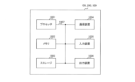
- FIG. 2 is a diagram illustrating an example of a hardware configuration of a base station, a relay device, and a terminal according to an embodiment of the present disclosure.
- FIG. 1 is a diagram illustrating an example of a configuration of a vehicle.
- existing technologies are used as appropriate.
- the existing technologies are, for example, existing LTE or existing NR, but are not limited to existing LTE and NR.
- SS Synchronization signal
- PSS Primary SS
- SSS Synchronization SS
- PBCH Physical broadcast channel
- PRACH Physical random access channel
- PDCCH Physical Downlink Control Channel
- PDSCH Physical Downlink Shared Channel
- PUCCH Physical Uplink Control Channel
- PUSCH Physical Uplink Shared Channel
- NR corresponds to NR-SS, NR-PSS, NR-SSS, NR-PBCH, NR-PRACH, etc.
- NR- even if a signal is used in NR, it is not necessarily specified as "NR-".
- the duplex method may be a TDD (Time Division Duplex) method, an FDD (Frequency Division Duplex) method, or another method (e.g., Flexible Duplex, etc.).
- TDD Time Division Duplex
- FDD Frequency Division Duplex
- another method e.g., Flexible Duplex, etc.
- “configuring" wireless parameters and the like may mean that predetermined values are pre-configured, or that wireless parameters notified from a base station or terminal are configured.
- the wireless communication system 10 is a wireless communication system conforming to 5G NR, and includes a Next Generation-Radio Access Network 20 (hereinafter, NG-RAN 20) and a terminal 200 (hereinafter, also referred to as UE (User Equipment) 200).
- NG-RAN 20 Next Generation-Radio Access Network
- UE User Equipment
- the wireless communication system 10 may be a wireless communication system conforming to a method called Beyond 5G, 5G Evolution, or 6G.
- NG-RAN 20 includes a base station 100 (hereinafter also referred to as gNB 100). Note that the number of gNBs and UEs is not limited to the example shown in FIG. 1.
- NG-RAN 20 actually includes multiple NG-RAN nodes, specifically, gNBs (or ng-eNBs), and is connected to a 5G-compliant core network (5GC, not shown).
- gNB may be read as a network (NW).
- the gNB100 is, as an example, a base station conforming to 5G, and performs wireless communication conforming to 5G with the UE200.
- a relay device 300 that relays signals is shown between the gNB100 and the UE200.
- the relay device 300 performs relay operations, for example, to transmit signals received from the gNB100 to the UE200, and to transmit signals received from the UE200 to the gNB100.
- relay may be replaced with “forward.”
- operation may be replaced with "processing,” "control,” etc.
- the relay device 300 considered in NR will be described in detail below.
- the gNB100 and UE200 may support MIMO (Multiple-Input Multiple-Output), which generates more directional beams by controlling radio signals transmitted from multiple antenna elements, carrier aggregation (CA: Carrier Aggregation), which bundles and uses multiple component carriers (CC: Component Carriers), and dual connectivity (DC: Dual Connectivity), which communicates between the UE and each of two NG-RAN nodes.
- MIMO Multiple-Input Multiple-Output
- CA Carrier Aggregation
- CC Component Carriers
- DC Dual Connectivity
- the wireless communication system 10 may support a plurality of frequency ranges (FR).
- Fig. 2 is a diagram showing an example of FRs used in the wireless communication system 10. As shown in Fig. 2, the wireless communication system 10 may support FR1 and FR2.
- the frequency bands of each FR are, for example, as follows: ⁇ FR1: 410MHz ⁇ 7.125GHz ⁇ FR2: 24.25GHz to 52.6GHz
- FR1 may use a sub-carrier spacing (SCS) of 15 kHz, 30 kHz or 60 kHz, and a bandwidth (BW) of 5 to 100 MHz.
- FR2 is a higher frequency than FR1, and may use an SCS of 60 kHz or 120 kHz (which may include 240 kHz), and a bandwidth (BW) of 50 to 400 MHz.
- SCS may also be interpreted as numerology. Numerology is defined in 3GPP TS 38.300 and corresponds to one subcarrier spacing in the frequency domain.
- the wireless communication system 10 may support a higher frequency band than the FR2 frequency band. Specifically, the wireless communication system 10 may support a frequency band exceeding 52.6 GHz up to 114.25 GHz. Such a high frequency band may be referred to as "FR2x" for convenience.
- FR2x frequency band exceeding 52.6 GHz
- CP-OFDM Cyclic Prefix - Orthogonal Frequency Division Multiplexing
- DFT-S-OFDM Discrete Fourier Transform - Spread - Orthogonal Frequency Division Multiplexing
- FIG. 3 is a diagram showing an example of the configuration of a radio frame (system frame), subframe, and slot used in the wireless communication system 10.
- one slot is composed of 14 symbols, and the larger (wider) the SCS is, the shorter the symbol period (and slot period) is.
- the SCS is not limited to the interval (frequency) shown in FIG. 3. For example, 480 kHz, 960 kHz, etc. may be used as the SCS.
- the number of symbols constituting one slot does not necessarily have to be 14 symbols (for example, it may be 28 or 56 symbols, etc.). Furthermore, the number of slots per subframe may differ depending on the SCS.
- time direction (t) shown in FIG. 3 may be called a time domain, a symbol period, or a symbol time, etc.
- frequency direction may be called a frequency domain, a resource block, a subcarrier, a bandwidth part (BWP), etc.
- the gNB100 transmits control information, configuration information, etc. of the gNB100 to the UE200 as a downlink (DL) signal.
- DL downlink
- gNB100 receives control information, data signals, information regarding the processing capabilities of UE200 (terminal capabilities (information); for example, UE capability), etc., from UE200 as uplink (UL) signals.
- the relay device 300 performs a forwarding operation to forward the DL signal to the UE 200.
- the relay device 300 also performs a forwarding operation to forward the UL signal to the gNB 100.
- the UL signal that the gNB 100 receives from the UE 200 and/or the DL signal that the UE 200 receives from the gNB 100 may be a signal relayed by the relay device 300.
- UE200 is a communication device equipped with wireless communication capabilities, such as a smartphone, mobile phone, tablet, wearable device, or M2M (Machine-to-Machine) communication module.
- wireless communication capabilities such as a smartphone, mobile phone, tablet, wearable device, or M2M (Machine-to-Machine) communication module.
- UE200 receives control signals or data signals from gNB100 in DL and transmits control signals or data signals to gNB100 in UL to utilize various communication services provided by wireless communication system 10.
- UE200 also receives various reference signals transmitted from gNB100 and performs measurement of propagation path quality based on the reception results of the reference signals.
- Channels used for transmitting DL signals include, for example, data channels and control channels.
- the data channel may include a physical downlink shared channel (PDSCH)
- the control channel may include a physical downlink control channel (PDCCH).
- PDSCH is an example of a downlink shared channel
- PDCCH is an example of a downlink control channel.
- PDCCH may be interpreted as downlink control information (DCI), control information, etc. transmitted in PDCCH.
- the reference signal included in the DL signal may include, for example, at least one of DMRS (Demodulation Reference Signal), PTRS (Phase Tracking Reference Signal), CSI-RS (Channel State Information - Reference Signal), SRS (Sounding Reference Signal), and PRS (Positioning Reference Signal) for position information.
- DMRS Demodulation Reference Signal
- PTRS Phase Tracking Reference Signal
- CSI-RS Channel State Information - Reference Signal
- SRS Sounding Reference Signal
- PRS Positioning Reference Signal
- reference signals such as DMRS and PTRS are used to demodulate the DL data signal and are transmitted using the PDSCH.
- Channels used for transmitting UL signals include, for example, data channels and control channels.
- the data channel may include a physical uplink shared channel (PUSCH)
- the control channel may include a physical uplink control channel (PUCCH).
- PUSCH is an example of an uplink shared channel
- PUCCH is an example of an uplink control channel.
- the shared channel may be called a data channel.
- PUSCH or PUCCH may be interpreted as uplink control information (UCI), control information, etc. transmitted in PUSCH or PUCCH.
- the reference signals included in the UL signal may include, for example, at least one of DMRS, PTRS, CSI-RS, SRS, and PRS for location information.
- reference signals such as DMRS and PTRS are used to demodulate the UL data signal and are transmitted using the PUSCH.
- NCR network-controlled repeater
- the NCR may correspond to, for example, the relay device 300 shown in FIG. 1.
- the relay device 300 may be described as NCR 300.
- the NCR may be replaced with terms such as a repeater, a forwarding device, and a communication device.
- NCRs may perform at least one of the following: control of the timing of transmission, control of the timing of reception, control of whether DL or UL operation is performed (e.g., switching), and control of ON/OFF of NCR operation.
- NCRs may also perform power control.
- NCRs are also capable of controlling the directivity in transmission and/or reception operations. That is, NCRs may control the transmitted beam and/or the received beam.
- NCR may also be referred to as NR NCR.
- the NCR is an inband radio frequency repeater used to extend network coverage in the FR1 and FR2 bands, based on the NCR model in TR38.867.
- the NCR is a single-hop, fixed-type device dedicated to NCR.
- NCR is transparent to the UE.
- the NCR may also simultaneously maintain a link between the gNB and the NCR (which may be referred to as a "gNB-repeater link”) and a link between the NCR and the UE (which may be referred to as a "repeater-UE link").
- gNB-repeater link a link between the gNB and the NCR
- UE a link between the UE and the UE
- NCR may support the following:
- side control information for controlling NCR-Fwd (described below) and specification of operation.
- the side control information includes, as an example, at least a part of information on beamforming, information on UL-DL operation, information on ON/OFF, and information on power control. Note that the aspect of power control is being discussed at a 3GPP meeting.
- the side control information may be simply called control information.
- control plane signalling and procedures For example, configuration of signaling of indication of side control information may be supported, although down-selection of the solution in Section 7.2 of TR 38.867 may be required.
- FIG. 4 is a diagram showing an example of the configuration of NCR300.
- NCR300 exists between UE200 and gNB100. Note that NCR300 may or may not exist between UE200 and gNB100 in the real space.
- NCR300 receives an UL signal addressed to gNB100 transmitted from UE200 and transmits it to the destination gNB100. In other words, NCR300 forwards an UL signal addressed to gNB100 transmitted from UE200 to the destination gNB100. NCR300 also receives a DL signal addressed to UE200 transmitted from gNB100 and transmits it to the destination UE200. In other words, NCR300 forwards a signal addressed to UE200 transmitted from gNB100 to the destination UE200.
- the NCR 300 may also operate based on control information (e.g., side control information) received from the gNB 100.
- control information e.g., side control information
- the link between NCR 300 and UE 200 may be referred to as an access link.
- the link that transmits signals received from UE 200 and addressed to gNB 100 may be referred to as a backhaul link.
- NCR 300 may receive signals addressed to UE 200 from gNB 100.
- the link that exchanges information between gNB 100 and NCR 300 may be referred to as a control link (hereinafter, may be referred to as a C-link).
- a control link hereinafter, may be referred to as a C-link
- side control information may be exchanged.
- FIG. 4 shows an example in which the gNB 100 included in the C-link and the gNB 100 included in the backhaul link are the same, the gNB 100 included in the C-link and the gNB 100 included in the backhaul link may be different from each other.
- the frequency e.g., carrier or frequency band
- the frequency used for communication in the backhaul link may be the same as each other, or at least two of the three may be different.
- one of the three frequencies may include another frequency.
- the link in the direction toward the gNB100 may be referred to as an uplink (UL), and the link in the direction opposite to the UL may be referred to as a downlink (DL).
- UL uplink
- DL downlink
- the frequency used for the UL communication of each of the three links and the frequency used for the DL communication may be the same as each other or may be different from each other.
- NCR-MT and NCR-Fwd The NCR 300 shown in FIG. 4 has two functional entities called NCR-MT and NCR-Fwd.
- NCR-MT and NCR-Fwd may be expressed by different names (for example, NCR_MT and NCR_Fwd).
- NCR_MT and NCR_Fwd may be expressed simply as MT
- Fwd Fwd
- the NCR-MT is a functional entity that communicates with gNB100 via a control link (C-link) and enables information exchange with gNB100.
- Information exchange with gNB100 may be, for example, sending and receiving side control information.
- the control link may also be based on the Uu interface of the NR.
- the NCR-MT may be considered to be equivalent to a UE.
- Instructions regarding communication control for the backhaul link may be specified (specified or provided) by the side control information.
- beam instructions for the backhaul link may be specified (specified or provided) by the side control information.
- Beam instructions correspond to instructions for the NCR to perform beam control. Beam instructions are issued, for example, from a gNB to the NCR. Beam instructions may include instructions for the beam to be used by the NCR, information regarding the resource for which the NCR will use the beam (e.g., a time resource (which may also be referred to as a time domain resource)), etc. Information regarding the time resource may be simply referred to as a time resource, as appropriate. Beam instructions may include instructions other than the above instructions, or may not include some of the above instructions.
- an "instruction” for a certain function may indicate information for performing that function (or operation), or may indicate an operation such as transmitting (or notifying) information for performing that function (or operation).
- "instruction” may be replaced with an indication, indicator, information, parameter, etc.
- a beam instruction may indicate information for performing beam control, or may indicate an operation such as transmitting (or notifying) information for performing beam control.
- the side control information may include at least information for controlling the NCR-Fwd. Furthermore, the side control information may be notified by at least one of the signaling of RRC (Radio Resource Control), MAC CE (Medium Access Control Element), and DCI (Downlink Control Information).
- RRC Radio Resource Control
- MAC CE Medium Access Control Element
- DCI Downlink Control Information
- the NCR-Fwd is a functional entity that transfers signals between the gNB and the UE via the backhaul link and the access link, respectively.
- the NCR-Fwd amplifies and transfers UL RF (Radio Frequency) signals, and also amplifies and transfers DL RF signals.
- the operation of the NCR-Fwd may be controlled according to side control information received from the gNB.
- the NCR 300 may have a reflection function of a signal transmitted from the base station 100 or the terminal 200.
- the reflection function may be a function related to phase change, a function related to beam control (e.g., a function related to control of the TCI state (Transmission Configuration Indication state), Quasi-Colocation (QCL), selective application of a beam, and selective application of a spatial filter/precoding weight).
- the TCI state is information related to the QCL of a signal/channel, and may be called spatial reception parameters, spatial relationship information, etc.
- the TCI state may be set in the NCR 300 and the terminal 200.
- the TCI state may be set in the NCR 300 and the terminal 200 for each channel or each signal.
- QCL is an index that indicates the statistical properties of a signal/channel. For example, if a signal/channel has a QCL relationship with another signal/channel, it may mean that it can be assumed that at least one of the Doppler shift, Doppler spread, average delay, delay spread, and spatial parameters (e.g., spatial Rx parameters) are identical between these different signals/channels (i.e., QCL with respect to at least one of these).
- a beam may correspond to QCL information, spatial relation, spatial domain parameter, spatial domain filter, TCI state, reference signal (RS) resource index, and SRS resource indicator (SRI).
- the terms beam, QCL information, spatial relation, spatial domain parameter, spatial domain filter, TCI state, RS resource index, and SRI may be considered synonymous or similar, and may be interchangeable.
- the beam instruction for the backhaul (BH) link also called backhaul link beam instruction
- the beam for the backhaul link is sometimes called the backhaul link beam or the backhaul beam.
- the NCR's backhaul link beam may be instructed by the MAC CE.
- the DL backhaul beam is directed by the MAC CE by the TCI state ID (TCI state ID) from the list of beams for C-link (also called C-link beams) configured in the RRC, and the UL backhaul beam is directed by the MAC CE by the C-link SRI.
- TCI state ID TCI state ID
- C-link also called C-link beams
- the UL backhaul beam is directed by the MAC CE by the C-link SRI.
- the Rel-15 beam direction framework specifies the TCI state or spatial relationship for each channel.
- the DL backhaul beam is directed by the MAC CE with a TCI status ID from the list of C-link beams configured in the RRC
- the UL backhaul beam is directed by the MAC CE with a TCI status ID from the list of C-link beams configured in the RRC.
- the Rel-17 beam direction framework may direct a common beam and apply the common beam to all UL and DL channels, or apply a common beam for UL to all UL channels and apply a common beam for DL to all DL channels.
- the NCR-MT may have multiple carriers/serving cells (CA) and the NCR-Fwd may operate on multiple carriers/cells.
- CA carriers/serving cells
- the DL backhaul link beam is instructed by the MAC CE by instructing the TCI state of the C-link of the NCR-MT
- the UL backhaul link beam is instructed by the MAC CE by instructing the TCI state or SRI of the C-link of the NCR-MT
- the NCR-MT (C-link) operates with multiple carriers/serving cells/BWPs
- the MAC CE determines whether the beam of the NCR backhaul link is instructed by the MAC CE.
- the DL backhaul link beam is instructed by the MAC CE by instructing the TCI state of the C-link of the NCR-MT
- the UL backhaul link beam is instructed by the MAC CE by instructing the TCI state or SRI of the C-link of the NCR-MT.
- both the Rel-15 beam pointing framework and the Rel-17 beam pointing framework can be used for the NCR-MT, but since the operation related to beam control differs when the Rel-15 beam pointing framework is used and when the Rel-17 beam pointing framework is used, if the configuration of the MAC CE used for backhaul link beam pointing is not clarified, it may adversely affect the operation of the NCR and may not be possible to properly relay signals (Problem 2).
- the beam instruction may be referred to as (control) information regarding the beam, etc.
- the TCI status (ID), SRI, beam index, etc. may be referred to as (control) information regarding the beam, beam information, information corresponding to the beam, information for identifying or specifying the beam, etc.
- NCR-MT in Rel-18 does not support CA.
- One NCR-MT may operate with only one serving cell (it may be configured with only one serving cell or only one serving cell may be configured).
- NCR-MT in Rel-18 supports CA.
- One NCR-MT may be configured to operate with multiple serving cells (may be configured to have multiple serving cells or multiple serving cells may be configured).
- NCR-MT in Rel-18 does not support being configured with multiple BWPs on a serving cell (multiple BWPs being configured on a serving cell).
- a Rel-18 NCR-MT may be configured to have multiple BWPs on the serving cell (multiple BWPs may be configured on the serving cell).
- a Rel-18 NCR-MT may be configured to have multiple BWPs in a serving cell (whether multiple BWPs may be set in a serving cell) is an optional NCR feature, and this may be reported in the RRC or OAM.
- ⁇ Proposal 2> In relation to problem 1, when the backhaul link beam of the NCR is instructed by the MAC CE, the DL backhaul link beam is instructed by the MAC CE by instructing the TCI status of the C-link of the NCR-MT, and the UL backhaul link beam is instructed by the MAC CE by instructing the TCI status or SRI of the C-link, and when the NCR-MT is configured to have multiple serving cells or to have multiple BWPs at the serving cell as shown in Proposal 1, the instructed TCI status/SRI of the C-link may be based on Options 1 and 2 below.
- the TCI status/SRI of the indicated NCR-MT C-link may be the TCI status/SRI of a particular serving cell of the NCR-MT.
- the TCI status/SRI of the indicated NCR-MT C-link may be, for example, the TCI status/SRI of a particular serving cell of the NCR-MT that is selected, determined or set based on specific conditions/rules such as those shown below.
- the specific serving cell is the PCell (primary cell) of the NCR-MT.
- the particular serving cell is the serving cell of the NCR-MT with the highest/lowest cell index. If the band of the carrier/cell of the NCR-Fwd backhaul link is the same as the band of the carrier/serving cell of the NCR-MT, then the particular serving cell is the serving cell.
- the particular serving cell is the serving cell. If the center frequency of the carrier/cell of the NCR-Fwd backhaul link is the same as the center frequency of the carrier/serving cell of the NCR-MT, then the particular serving cell is the serving cell. If the bandwidth of the carrier/cell of the NCR-Fwd backhaul link is within the bandwidth of the carrier/serving cell of the NCR-MT, then the particular serving cell is the serving cell.
- the particular serving cell is the serving cell. If the bandwidth of the carrier/cell of the NCR-Fwd backhaul link overlaps with the bandwidth of the carrier/serving cell of the NCR-MT, then the particular serving cell is the serving cell.
- one serving cell of the NCR-MT is selected, determined or configured according to further rules, for example, if the PCell of the NCR-MT satisfies the conditions, the PCell of the NCR-MT is selected, determined or configured, the serving cell of the NCR-MT having the highest/lowest cell index is selected, determined or configured, etc.
- NCR 300 may select, determine or set a specific serving cell corresponding to the indicated TCI state/SRI based on specific conditions/rules as shown above.
- the indicated TCI status/SRI of the NCR-MT C-link may be the TCI status/SRI of a specific serving cell of the NCR-MT, which is set (e.g., explicitly) by the network in side control information via RRC/MAC CE/DCI, for example.
- the specific serving cell e.g., serving cell ID
- MAC CE e.g., MAC CE described below
- NCR 300 receives information (e.g., serving cell ID) regarding a specific serving cell of NCR-MT from base station 100 via RRC/MAC CE/DCI, and may select, determine or set a specific serving cell corresponding to the indicated TCI state/SRI based on this information.
- information e.g., serving cell ID
- the TCI status/SRI of the indicated NCR-MT C-link may be the TCI status/SRI of the NCR-MT's BWP.
- the TCI status/SRI of the indicated NCR-MT C-link may be the TCI status/SRI of a particular BWP of the NCR-MT that is selected, determined or set based on specific conditions/rules, for example, as shown below.
- the particular BWP is the active DL/UL BWP of the NCR-MT.
- the particular BWP is the DL/UL BWP of the NCR-MT with the highest/lowest BWP index.
- NCR 300 may select, determine or set a specific BWP corresponding to the indicated TCI state/SRI based on specific conditions/rules as shown above.
- the indicated TCI state/SRI of the NCR-MT C-link may be the TCI state/SRI of a particular BWP of the NCR-MT, which is set (e.g., explicitly) by the network in side control information via RRC/MAC CE/DCI, for example.
- a particular BWP e.g., BWP ID
- MAC CE e.g., MAC CE described below
- NCR 300 receives information (e.g., BWP ID) regarding a specific BWP of NCR-MT from base station 100 via RRC/MAC CE/DCI, and may select, determine or set a specific BWP corresponding to the indicated TCI state/SRI based on this information.
- information e.g., BWP ID
- BWP ID information regarding a specific BWP of NCR-MT from base station 100 via RRC/MAC CE/DCI
- the TCI status/SRI of different serving cells of the NCR-MT may be indicated for different carriers/cells of the NCR-Fwd.
- the indicated TCI status/SRI of the NCR-MT C-link may be the TCI status/SRI of a specific serving cell of the NCR-MT, which is selected, determined or set based on specific conditions/rules, for example, as shown below. If the band of the carrier/cell of the NCR-Fwd backhaul link is the same as the band of the carrier/serving cell of the NCR-MT, then the particular serving cell is the serving cell. If the bandwidth of the carrier/cell of the NCR-Fwd backhaul link is the same as the bandwidth of the carrier/serving cell of the NCR-MT, then the particular serving cell is the serving cell.
- the particular serving cell is the serving cell. If the bandwidth of the carrier/cell of the NCR-Fwd backhaul link is within the bandwidth of the carrier/serving cell of the NCR-MT, then the particular serving cell is the serving cell. If the bandwidth of the carrier/serving cell of the NCR-MT is within the bandwidth of the carrier/cell of the NCR-Fwd backhaul link, then the particular serving cell is the serving cell.
- the particular serving cell is the serving cell.
- the carrier/cell of the NCR-Fwd backhaul link is configured to have the same cell index as the carrier/serving cell of the NCR-MT (the same cell index is set as the carrier/serving cell of the NCR-MT), then the particular serving cell is that serving cell.
- one serving cell of the NCR-MT is selected, determined or configured according to further rules, for example, if the PCell of the NCR-MT satisfies the conditions, the PCell of the NCR-MT is selected, determined or configured, the serving cell of the NCR-MT having the highest/lowest cell index is selected, determined or configured, etc.
- NCR 300 may select, determine or set a specific BWP corresponding to the indicated TCI state/SRI for each carrier/cell of the NCR-Fwd backhaul link based on specific conditions/rules as shown above.
- the indicated NCR-MT C-link TCI status/SRI may be the TCI status/SRI of a specific serving cell of the NCR-MT, e.g., configured (e.g., explicitly) by the network in side control information via RRC/MAC CE/DCI.
- the specific serving cell e.g., serving cell ID
- the MAC CE/DCI carrying the NCR backhaul link beam indication may be included in the MAC CE/DCI carrying the NCR backhaul link beam indication.
- NCR 300 receives information (e.g., serving cell ID) regarding a specific serving cell of NCR-MT for each carrier/cell of the NCR-Fwd backhaul link from base station 100 via RRC/MAC CE/DCI, and may select, determine or set a specific serving cell corresponding to the indicated TCI state/SRI based on this information.
- information e.g., serving cell ID
- the TCI status/SRI of different BWPs of the NCR-MT may be indicated for different carriers/cells of the NCR-Fwd.
- the indicated TCI status/SRI of the NCR-MT C-link may be the TCI status/SRI of a particular BWP of the NCR-MT, which is selected, determined or set based on specific conditions/rules, for example, as shown below.
- the particular BWP is the active DL/UL BWP of the NCR-MT.
- the particular BWP is the DL/UL BWP of the NCR-MT with the highest/lowest BWP index.
- NCR 300 may select, determine or set a specific BWP corresponding to the indicated TCI state/SRI for each carrier/cell of the NCR-Fwd backhaul link based on specific conditions/rules as shown above.
- the indicated NCR-MT C-link TCI state/SRI may be the TCI state/SRI of a specific BWP of the NCR-MT, which is set (e.g., explicitly) by the network in side control information via the RRC/MAC CE/DCI.
- the specific BWP e.g., BWP ID
- the MAC CE/DCI carrying the NCR backhaul link beam indication may be included in the MAC CE/DCI carrying the NCR backhaul link beam indication.
- NCR 300 may receive information (e.g., BWP ID) regarding a specific BWP of NCR-MT for each carrier/cell of the NCR-Fwd backhaul link from base station 100 via RRC/MAC CE/DCI, and may select, determine or set a specific BWP corresponding to the indicated TCI state/SRI based on this information.
- BWP ID information regarding a specific BWP of NCR-MT for each carrier/cell of the NCR-Fwd backhaul link from base station 100 via RRC/MAC CE/DCI
- One MAC CE may include either an NCR backhaul DL beam indication or an NCR backhaul UL beam indication.
- a different MAC CE (having a different LCID (Logical Channel ID)) may be used for the NCR backhaul DL beam instruction and the NCR backhaul UL beam instruction.
- LCID Logical Channel ID
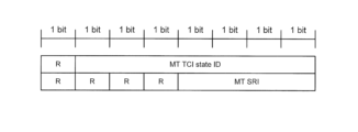
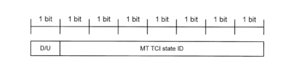
- the MAC CE for NCR backhaul DL beam instruction may have a configuration in which the most significant bit is a reserved bit (denoted as "R”; similarly in other figures) and the lowest 7 bits have an "MT TCI state ID" field.
- the information indicated in this field may be the MT TCI state (ID). Note that the bit arrangement shown in various figures, including Figure 5A, is not limited to the example shown.
- the MAC CE for NCR backhaul UL beam instruction may have a configuration in which the upper four bits are reserved bits and the lower four bits have an "MT SRI" field.
- the information indicated in this field may be the MT SRI.
- NCR300 may determine whether the MAC CE instructs a DL beam or a UL beam by identifying the LCID.
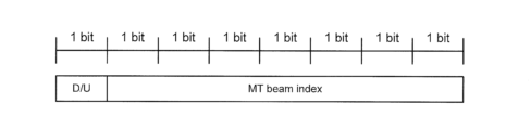
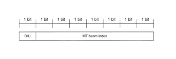
- the same MAC CE may be used for NCR backhaul DL beam indication and NCR backhaul UL beam indication, and a certain field in this same MAC CE may indicate whether this same MAC CE indicates a DL beam or a UL beam.
- the same MAC CE may have a configuration in which the most significant bit is a "D/U" field indicating either a DL beam or a UL beam, and the lowest 7 bits are an "MT beam index” field.
- the "0" and “1” that the "D/U” field can take may have opposite meanings. That is, “1" may indicate a UL beam, and "0" may indicate a DL beam.
- NCR300 may determine whether the MAC CE indicates a DL beam or a UL beam based on the value of a certain field (e.g., the "D/U" field) in the MAC CE.
- a certain field e.g., the "D/U" field
- One MAC CE may always include both NCR backhaul DL beam indication and NCR backhaul UL beam indication.
- one MAC CE may have a configuration that combines the configuration of a MAC CE for NCR backhaul DL beam instruction shown in FIG. 5A and the configuration of a MAC CE for NCR backhaul UL beam instruction.
- One MAC CE may include both an NCR backhaul DL beam indication and an NCR backhaul UL beam indication, or may include only an NCR backhaul DL beam indication, or may include only an NCR backhaul UL beam indication.
- a field in the MAC CE may indicate whether the MAC CE includes both an NCR backhaul DL beam indication and an NCR backhaul UL beam indication, or includes only an NCR backhaul DL beam indication, or includes only an NCR backhaul UL beam indication.
- this MAC CE may have a 2-bit "D/U" field in one octet indicating whether this MAC CE includes both an NCR backhaul DL beam indication and an NCR backhaul UL beam indication, or includes only an NCR backhaul DL beam indication, or includes only an NCR backhaul UL beam indication, and may have an "MT beam index" field in the lowest 7 bits in each of the two octets.
- the "D/U" field is "00" (indicating only DL beam)
- the "D/U" field is "01" (indicating only a UL beam)
- the "D/U” field is "10” (indicating both a DL beam and a UL beam)
- "11" is reserved.
- NCR300 may determine whether the MAC CE indicates both DL and UL beams, only DL beams, or only UL beams based on the value of a certain field (e.g., the "D/U" field) in the MAC CE.
- a certain field e.g., the "D/U" field
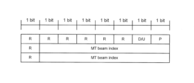
- a field in a MAC CE may indicate whether the MAC CE includes both or one of an NCR backhaul DL beam indication and an NCR backhaul UL beam indication. And if the field indicates that the MAC CE includes one of an NCR backhaul DL beam indication and an NCR backhaul UL beam indication, another field in the MAC CE may indicate whether the MAC CE includes an NCR backhaul DL beam indication or an NCR backhaul UL beam indication.
- the MAC CE may have a one-bit "P" field indicating whether the MAC CE includes both or one of an NCR backhaul DL beam indication and an NCR backhaul UL beam indication in one octet, a "D/U” field indicating whether the MAC CE includes an NCR backhaul DL beam indication or an NCR backhaul UL beam indication, and two "MT beam index" fields as described with reference to FIG. 5D.
- the MAC CE includes both an NCR backhaul DL beam indication and an NCR backhaul UL beam indication
- the same explanation as when the "D/U” field is "10" (indicating both DL beam and UL beam) as described with reference to FIG. 5D may be applied.
- the "P" field is "0” (this MAC CE includes either an NCR backhaul DL beam instruction or an NCR backhaul UL beam instruction) and the "D/U” field is "0” (indicating a DL beam)
- the same explanation as for the case where the "D/U” field is "00" (indicating only a DL beam) described with reference to Figure 5D may apply.
- NCR300 may determine whether the MAC CE indicates both DL beams and UL beams or one of them based on the value of a certain field in the MAC CE (e.g., the "P" field). If indicating one of DL beams and UL beams, NCR300 may determine whether the MAC CE indicates DL beams or UL beams based on the value of another field in the MAC CE (e.g., the "D/U" field).
- One MAC CE may include one beam index (e.g., TCI state ID) that applies to and is indicated for both the NCR backhaul DL and the NCR backhaul UL.
- one beam index e.g., TCI state ID
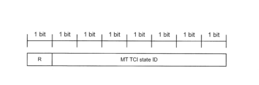
- Option 4 may be applicable when the DL and UL have beam correspondence.
- this MAC CE may have a configuration with an "MT TCI State ID" field in the lowest 7 bits.
- the indicated MT TCI state may apply to both the NCR backhaul DL and the NCR backhaul UL.
- the NCR MT serving cell ID/NCR MT BWP ID/NCR MT DL BWP ID/NCR MT UL BWP ID may be included in accordance with Proposal 2.
- NCR300 operates, for example, as follows.
- NCR300 e.g., NCR-MT
- NCR300 receives a list of beams that NCR300 can use in the backhaul link (list of C-link beams) from base station 100 via C-link by RRC signaling.
- NCR300 receives the above-mentioned MAC CE including beam instructions regarding the beams that NCR300 will use in the backhaul link via C-link.
- NCR300 (e.g., NCR-Fwd) determines the beam that NCR300 will use in the backhaul link from the list of beams that NCR300 can use based on the beam instructions, for example by making the above-mentioned judgment.
- joint DL/UL TCI (common or identical TCI for DL and UL) is configured in the NCR-MT
- one TCI state may be indicated and applied to both the NCR backhaul DL and the NCR backhaul UL.
- joint DL/UL TCI means that a common or identical TCI may be indicated and applied to the NCR-MT DL channel/reference signal (RS) and the NCR-MT UL channel/RS.
- RS DL channel/reference signal
- One MAC CE may include, for example, one "TCI State ID" field.
- this MAC CE may have a "MT TCI State ID” field in the lowest 7 bits.
- the "MT TCI State ID” field may indicate the joint DL/UL TCI state (ID) of the NCR MT.
- ⁇ Case 2>> When separate DL/UL TCI (separate TCI for DL and UL) is configured in NCR-MT, separate TCI states may be indicated for NCR backhaul DL and NCR backhaul UL, respectively.
- separate DL/UL TCI means that separate TCI may be indicated and applied to NCR-MT DL channel/RS and NCR-MT UL channel/RS, respectively.
- Options 1 to 3 described below are similar to Options 1 to 3 in Proposal 2, respectively.
- One MAC CE may include either an NCR backhaul DL beam indication or an NCR backhaul UL beam indication.
- Different MAC CEs may be used for the NCR backhaul DL beam indication and the NCR backhaul UL beam indication.
- the MAC CE for NCR backhaul DL beam instruction may have a configuration in which the most significant bit is a reserved bit and the lowest 7 bits have an "MT TCI status ID" field.
- This "MT TCI status ID” field may indicate the DL TCI status (ID) of the NCR-MT.
- the MAC CE for NCR backhaul UL beam instruction may be configured so that the upper two bits are reserved bits and the lower six bits have an "MT TCI status ID" field.
- This "MT TCI status ID” field may indicate the UL TCI status (ID) of the NCR-MT.
- NCR300 may determine whether the MAC CE instructs a DL beam or a UL beam by identifying the LCID.
- the same MAC CE may be used for NCR backhaul DL beam indication and NCR backhaul UL beam indication, and a certain field in this same MAC CE may indicate whether this same MAC CE indicates a DL beam or a UL beam.
- the same MAC CE may have a configuration in which the most significant bit is a "D/U” field indicating either DL beam or UL beam, and the lowest 7 bits are an "MT TCI Status ID” field.
- ID the MT UL TCI status
- the "0” and “1” that the "D/U” field can take may have opposite meanings. That is, “1” may indicate a UL beam and "0" may indicate a DL beam.
- NCR300 may determine whether the MAC CE indicates a DL beam or a UL beam based on the value of a certain field (e.g., the "D/U" field) in the MAC CE.
- a certain field e.g., the "D/U" field
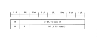
- One MAC CE may always include both NCR backhaul DL beam indication and NCR backhaul UL beam indication.
- one MAC CE may have a configuration that combines the configuration of a MAC CE for NCR backhaul DL beam instruction shown in FIG. 6B and the configuration of a MAC CE for NCR backhaul UL beam instruction.
- the "MT DL TCI Status ID” field may indicate the DL TCI status (ID) of the NCR-MT
- the "MT UL TCI Status ID” field may indicate the UL TCI status (ID) of the NCR-MT.
- One MAC CE may include both an NCR backhaul DL beam indication and an NCR backhaul UL beam indication, or may include only an NCR backhaul DL beam indication, or may include only an NCR backhaul UL beam indication.
- a field in the MAC CE may indicate whether the MAC CE includes both an NCR backhaul DL beam indication and an NCR backhaul UL beam indication, or includes only an NCR backhaul DL beam indication, or includes only an NCR backhaul UL beam indication.
- this MAC CE may have a 2-bit "D/U" field in one octet indicating whether this MAC CE includes both an NCR backhaul DL beam indication and an NCR backhaul UL beam indication, or includes only an NCR backhaul DL beam indication, or includes only an NCR backhaul UL beam indication, and may have an "MT TCI State ID" field in the lowest 7 bits in each of the two octets.
- the "D/U” field is "01" (indicating only a UL beam)
- the "D/U" field is "10" (indicating both DL and UL beams)
- “11” is reserved. Note that "00", “01”, “10”, and “11” that the "D/U” field can take may have interchangeable meanings. For example, “00” may indicate only a UL beam, "01” may indicate both a DL beam and a UL beam, and "11” may indicate only a DL beam, etc.
- NCR300 may determine whether the MAC CE indicates both DL and UL beams, only DL beams, or only UL beams based on the value of a certain field (e.g., the "D/U" field) in the MAC CE.
- a certain field e.g., the "D/U" field
- a field in a MAC CE may indicate whether the MAC CE includes both or one of an NCR backhaul DL beam indication and an NCR backhaul UL beam indication. And if the field indicates that the MAC CE includes one of an NCR backhaul DL beam indication and an NCR backhaul UL beam indication, another field in the MAC CE may indicate whether the MAC CE includes an NCR backhaul DL beam indication or an NCR backhaul UL beam indication.
- the MAC CE may have a one-bit "P" field indicating whether the MAC CE includes both or one of the NCR backhaul DL beam indication and the NCR backhaul UL beam indication in one octet, a "D/U” field indicating whether the MAC CE includes the NCR backhaul DL beam indication or the NCR backhaul UL beam indication, and two "MT TCI State ID” fields as described with reference to FIG. 6E.
- P one-bit "P” field indicating whether the MAC CE includes both or one of the NCR backhaul DL beam indication and the NCR backhaul UL beam indication in one octet
- D/U field indicating whether the MAC CE includes the NCR backhaul DL beam indication or the NCR backhaul UL beam indication
- two "MT TCI State ID" fields as described with reference to FIG. 6E.
- NCR300 may determine whether the MAC CE indicates both DL beams and UL beams or one of them based on the value of a certain field in the MAC CE (e.g., the "P" field). If indicating one of DL beams and UL beams, NCR300 may determine whether the MAC CE indicates DL beams or UL beams based on the value of another field in the MAC CE (e.g., the "D/U" field).
- case 2 when a joint DL/UL TCI is configured in the NCR-MT, separate TCI states may be indicated for the NCR backhaul DL and NCR backhaul UL, respectively.
- options 1 to 3 of case 2 described above may be applied.
- the NCR MT serving cell ID/NCR MT BWP ID/NCR MT DL BWP ID/NCR MT UL BWP ID may be included in accordance with Proposal 2.
- NCR300 operates, for example, as follows.
- NCR300 e.g., NCR-MT
- NCR300 receives a list of beams that NCR300 can use in the backhaul link (list of C-link beams) from base station 100 via C-link by RRC signaling.
- NCR300 receives the above-mentioned MAC CE including beam instructions regarding the beams that NCR300 will use in the backhaul link via C-link.
- NCR300 (e.g., NCR-Fwd) determines the beam that NCR300 will use in the backhaul link from the list of beams that NCR300 can use based on the beam instructions, for example by making the above-mentioned judgment.
- the NCR 300 may determine whether the MAC CE is for a joint DL/UL TCI case or a separate DL/UL TCI case by identifying the LCID.
- the same MAC CE may be used for both the joint DL/UL TCI case and the separate DL/UL TCI case.
- a field in the same MAC CE may indicate whether it is a joint DL/UL TCI case or a separate DL/UL TCI case (whether this same MAC CE is for the joint DL/UL TCI case or the separate DL/UL TCI case).
- the same MAC CE may have a 1-bit "P" field indicating whether the case is a joint DL/UL TCI or a separate DL/UL TCI, and indicating whether one or both of the two "MT TCI Status ID” fields below are indicated, and may have two "MT TCI Status ID” fields.
- the "P" field is "0" (indicating the joint DL/UL TCI case)
- one of the two "MT TCI Status ID” fields is indicated, and the information indicated in this field may be the joint DL/UL TCI status (ID).
- the "P" field is "1" (indicating the case of separate DL/UL TCI)
- the "0” and “1” that the "P” field can take may have opposite meanings. That is, "0" may indicate the case of separate DL/UL TCI, and "1" may indicate the case of joint DL/UL TCI.
- NCR300 may determine whether a MAC CE is for a joint DL/UL TCI case or a separate DL/UL TCI case based on the value of a certain field (e.g., the "P" field) in the MAC CE.
- a certain field e.g., the "P" field
- -Option 2-2 Whether it is a joint DL/UL TCI case or a separate DL/UL TCI case (whether the same MAC CE is for the joint DL/UL TCI case or the separate DL/UL TCI case) may be based on higher layer configuration (e.g., RRC configuration).
- higher layer configuration e.g., RRC configuration
- the MAC CE may have a one-bit "P" field in one octet indicating whether one or both of the two "MT TCI Status ID" fields below are indicated, a "D/U” field indicating whether this MAC CE includes an NCR backhaul DL beam indication or an NCR backhaul UL beam indication, and a "MT TCI Status ID” field in the lowest 7 bits in each of the two octets.
- one of the two "MT TCI Status ID” fields may be indicated.
- the information indicated in this field may be the joint DL/UL TCI status (ID).
- the "D/U” field may not be present.
- the information indicated in one of the two "MT TCI Status ID” fields may be different depending on the value of the "D/U” field.
- the "0” and “1” that the "P” field can take may represent opposite meanings, and the "0” and “1” that the "D/U” field can represent opposite meanings. That is, with respect to the "P” field, a “1” may indicate that one "MT TCI Status ID” field is indicated, and a “0” may indicate that two "MT TCI Status ID” fields are indicated. Also, with respect to the "D/U” field, a "0” may indicate a UL beam, and a “1” may indicate a DL beam.
- the MAC CE configuration of the above-mentioned options 2 and 3 in Proposal 4 is used and the upper layer sets the case of joint DL/UL TCI, one "MT TCI Status ID" field is indicated, and the information indicated in this field may be the joint DL/UL TCI status (ID). In this case, other fields may not be present.
- the MAC CE configuration of the above-mentioned options 2 and 3 in Proposal 4 is used and the upper layer sets the case of separate DL/UL TCI, the respective explanations of options 2 and 3 in Proposal 4 may be applied.
- NCR300 may determine whether the MAC CE is for the joint DL/UL TCI case or the separate DL/UL TCI case based on higher layer configuration (e.g., RRC configuration).
- higher layer configuration e.g., RRC configuration
- the configuration (contents) of the MAC CE in the case of a joint DL/UL TCI and the configuration (contents) of the MAC CE in the case of a separate DL/UL TCI may be the same or similar to the configuration (contents) described above in Proposal 4 (see, for example, Figures 6A to 6F).
- NCR 300 operates, for example, as follows: NCR 300 (e.g., NCR-MT) receives a list of beams that NCR 300 can use in the backhaul link (list of C-link beams) from base station 100 via C-link by RRC signaling. NCR 300 may also receive configuration information regarding whether to use the joint DL/UL TCI case or the separate DL/UL TCI case from base station 100 via C-link by RRC signaling. NCR 300 (e.g., NCR-MT) receives a MAC CE including beam instructions regarding the beams that NCR 300 will use in the backhaul link via C-link.
- NCR 300 receives a list of beams that NCR 300 can use in the backhaul link (list of C-link beams) from base station 100 via C-link by RRC signaling.
- NCR 300 may also receive configuration information regarding whether to use the joint DL/UL TCI case or the separate DL/UL TCI case from base station 100 via C-link by RRC signaling.
- the NCR 300 determines whether to use the joint DL/UL TCI case or the separate DL/UL TCI case, and determines the beam that the NCR 300 will use in the backhaul link from the list of beams that the NCR 300 can use.
- Proposal 5 clarifies the configuration of the MAC CE when the Rel-17 beam pointing framework is used for NCR-MT, and allows signals to be relayed appropriately.
- the relationship between the MAC CE for the Rel-15 beam pointing framework case and the MAC CE for the Rel-17 beam pointing framework case may be the relationship shown in Options 1 and 2 below.
- the Rel-15 beam pointing framework case means the case where the Rel-15 beam pointing framework is used for NCR-MT
- the Rel-17 beam pointing framework case means the case where the Rel-17 beam pointing framework is used for NCR-MT.
- NCR300 may determine whether the MAC CE is for the Rel-15 beam pointing framework case or the Rel-17 beam pointing framework case by identifying the LCID.
- the same MAC CE may be used for both the Rel-15 beampointing framework case and the Rel-17 beampointing framework case.
- a field in the same MAC CE may indicate whether it is for the Rel-15 beam pointing framework case or the Rel-17 beam pointing framework case (whether this same MAC CE is for the Rel-15 beam pointing framework case or the Rel-17 beam pointing framework case).
- NCR300 may determine whether a MAC CE is for the Rel-15 beam pointing framework case or the Rel-17 beam pointing framework case based on the value of a certain field in the MAC CE.
- -Option 2-2 Whether it is a Rel-15 beam pointing framework case or a Rel-17 beam pointing framework case (whether the same MAC CE is for the Rel-15 beam pointing framework case or the Rel-17 beam pointing framework case) may be based on higher layer configuration (e.g., RRC configuration).
- higher layer configuration e.g., RRC configuration
- the information indicated in the lower 7 bits of the "MT beam index” field shown in FIG. 8A may be different depending on the higher layer settings.
- the "MT beam index” field may indicate the MT TCI state (ID).
- the "MT beam index” field may indicate the MT joint DL/UL TCI state (ID) and may be applied to both the NCR backhaul DL and the NCR backhaul UL.
- the information indicated in the lower 7 bits of the "MT beam index” field shown in FIG. 8B may be different depending on the higher layer setting.
- the "MT beam index” field may indicate the MT TCI state (ID) or the SRI in accordance with the explanation above in Option 1-2 of Proposal 3.
- the "MT beam index” field may indicate the MT DL TCI state (ID) or the MT UL TCI state (ID) in accordance with the explanation above in Option 1-2 of Proposal 4.
- the information indicated in the lower 6 bits of the "MT UL beam index" field shown in FIG. 8C may be different depending on the upper layer configuration.
- the "MT UL beam index” field may indicate the MT SRI in accordance with the explanation above in Option 2 of Proposal 3.
- the "MT UL beam index” field may indicate the MT UL TCI status (ID) in accordance with the explanation above in Option 2 of Proposal 4.
- the information indicated in the lower 7 bits of the "MT beam index” field shown in FIG. 8D may be different depending on the higher layer setting.
- the "MT beam index” field may indicate the MT TCI state (ID) or the SRI in accordance with the explanation above in Option 3 of Proposal 3.
- the "MT beam index” field may indicate the MT DL TCI state (ID) or the MT UL TCI state (ID) in accordance with the explanation above in Option 3 of Proposal 4.
- the information indicated in the lower 7 bits of the "MT beam index” field shown in FIG. 8E may be different depending on the upper layer setting.
- the "MT beam index” field may indicate the MT TCI state (ID) or the SRI in accordance with the explanation above in the variation of option 3 of proposal 3.
- the "MT beam index” field may indicate the MT DL TCI state (ID) or the MT UL TCI state (ID) in accordance with the explanation above in the variation of option 3 of proposal 4.
- NCR300 may determine whether the MAC CE is for the Rel-15 beam pointing framework case or the Rel-17 beam pointing framework case based on higher layer configuration (e.g., RRC configuration).
- higher layer configuration e.g., RRC configuration
- the configuration (contents) of the MAC CE in the case of the Rel-15 beam pointing framework and the configuration (contents) of the MAC CE in the case of the Rel-17 beam pointing framework may be the same or similar to the configuration (contents) described above in Proposals 3 and 4 (see, for example, Figures 5A to 5F and Figures 6A to 6F).
- NCR 300 operates, for example, as follows: NCR 300 (e.g., NCR-MT) receives a list of beams that NCR 300 can use in the backhaul link (list of C-link beams) from base station 100 via C-link by RRC signaling. NCR 300 may also receive configuration information regarding whether to use the Rel-15 beam instruction framework case or the Rel-17 beam instruction framework case from base station 100 via C-link by RRC signaling. NCR 300 (e.g., NCR-MT) receives a MAC CE including beam instructions regarding the beams that NCR 300 will use in the backhaul link via C-link.
- NCR 300 receives a list of beams that NCR 300 can use in the backhaul link (list of C-link beams) from base station 100 via C-link by RRC signaling.
- NCR 300 may also receive configuration information regarding whether to use the Rel-15 beam instruction framework case or the Rel-17 beam instruction framework case from base station 100 via C-link by RRC signaling.
- NCR 300
- the NCR 300 determines whether to use the Rel-15 beam instruction framework case or the Rel-17 beam instruction framework case, and determines the beam that the NCR 300 will use in the backhaul link from the list of beams that the NCR 300 can use.
- Proposal 6 clarifies the configuration of the MAC CE when both the Rel-15 beam pointing framework and the Rel-17 beam pointing framework are used in NCR-MT, enabling appropriate signal relay.
- the base station 100 operates, for example, as follows.
- the base station 100 transmits a list of C-link beams to the NCR 300 (e.g., NCR-MT) by RRC signaling via the C-link.
- the base station 100 may transmit, by RRC signaling via the C-link, configuration information regarding whether to use the joint DL/UL TCI case or the separate DL/UL TCI case, and/or configuration information regarding whether to use the Rel-15 beam instruction framework case or the Rel-17 beam instruction framework case, to the NCR 300 (e.g., NCR-MT).
- the base station 100 transmits, by C-link, a MAC CE including a backhaul link beam instruction, which may be any of the MAC CEs described in the above proposal, to the NCR 300 (e.g., NCR-MT).
- the base station 100 communicates with the terminal 200 via the backhaul link and the access link, relaying through the NCR 300 (e.g., NCR-Fwd).
- FIG. 9 is a flowchart showing an example of the operation of the relay device (NCR) 300 according to the embodiment of the present disclosure.
- step S101 the NCR 300 receives a list of control link beams (C-link beams) from the base station 100 via the control link (C-link) by RRC signaling.
- step S102 the NCR 300 receives a MAC CE including a beam instruction from the base station 100 via the C-link.
- This MAC CE may be any of the MAC CEs described in the above proposal.
- NCR300 determines or sets a backhaul link beam based on the received list of control link beams (C-link beams) and MAC CE (beam instruction) as described in the above proposal. For example, NCR300 determines a beam corresponding to the TCI state (ID) or SRI in the MAC CE (beam instruction) from the list of control link beams (C-link beams) as the backhaul link beam.
- the backhaul link beam may be used when NCR300 receives control information or data addressed to terminal 200 transmitted from base station 100, or when NCR300 transmits control information or data addressed to base station 100 transmitted from terminal 200 and received by NCR300 to base station 100.
- step S104 the NCR 300 communicates with the base station 100 in the DL or UL via the backhaul link using the determined backhaul link beam.
- the NCR may report the following capabilities to the base station as capabilities related to beam pointing: Support for adaptive beam control for NCR backhaul links Support for NCR backhaul link beaming as directed by MAC CE
- the NCR may report the following capabilities for the frequency bands it supports: Capability for all bands (e.g., single capability) (e.g., capability as NCR) Capability per frequency band Capability per frequency range (e.g., capability in each of FR1/FR2, etc.) Note that a single capability may correspond to one capability for all frequency bands, rather than a capability for each frequency band.
- the NCR may report the following capabilities for supported duplex: All duplex capabilities (e.g. single capability) (e.g. repeater capability) Capabilities for each duplex (e.g., capabilities for each of TDD/FDD, etc.) It should be noted that a single capability may correspond to one capability for all duplexes, rather than a capability for each duplex.
- All duplex capabilities e.g. single capability
- Capabilities for each duplex e.g., capabilities for each of TDD/FDD, etc.
- the NCR may also report to the base station whether or not it supports each of the proposed options listed above as its capabilities.
- the above proposals may be applied if the corresponding capabilities are supported by the NCR and/or if the corresponding capabilities are enabled by higher layer signaling.
- the base station 100 and the terminal 200 may have the functions to implement the above-mentioned embodiment. However, the base station 100 and the terminal 200 may each have only a part of the functions of the embodiment.
- Fig. 10 is a block diagram showing an example of a configuration of a base station 100 according to an embodiment of the present disclosure.
- the base station includes, for example, a transmitting unit 101, a receiving unit 102, and a control unit 103.
- the base station 100 communicates with a terminal 200 (see Fig. 11) by radio.
- the transmitting unit 101 and the receiving unit 102 may be collectively referred to as a communication unit.
- the transmitting unit 101 transmits a DL signal to the terminal 200.
- the transmitting unit 101 transmits the DL signal under the control of the control unit 103.
- the DL signal may include information indicating scheduling regarding the signal transmission of the terminal 200 (for example, an UL grant), upper layer control information, etc.
- the transmitting unit 101 transmits various control signals (such as RRC layer control signals), reference signals, data signals, etc., as DL signals to the terminal 200 and/or relay device 300.
- the transmitting unit 101 transmits various signals, channels, setting information, control information, etc., described in the above embodiments, as DL signals to the terminal 200.
- the transmitting unit 101 transmits information regarding the control of the terminal 200 and/or information regarding the control of the relay device 300, which is generated by the control unit 103, to the terminal 200.
- the transmitting unit 101 also transmits a data signal generated by the control unit 103 to the terminal 200.
- the receiving unit 102 receives the UL signal transmitted from the terminal 200.
- the receiving unit 102 receives the UL signal under the control of the control unit 103.
- the receiving unit 102 may also receive the UL signal transmitted from the relay device 300.
- the receiving unit 102 receives, as an UL signal, a signal including the terminal capability information (e.g., UE capability) of the terminal 200, various control signals, reference signals, data signals, etc. from the terminal 200.
- the receiving unit 102 may also receive a signal including the capability information (e.g., NCR capability) of the relay device 300.
- the control unit 103 controls the overall (communication) operation of the base station 100, including the transmission processing in the transmission unit 101 and the reception processing in the reception unit 102.
- control unit 103 acquires information such as data and control information from the upper layer and outputs it to the transmission unit 101.
- the control unit 103 also outputs data and control information received from the reception unit 102 to the upper layer.
- control unit 103 allocates resources to be used for transmitting and receiving DL signals and/or resources to be used for transmitting and receiving UL signals based on a signal (e.g., data and control information, etc.) received from the terminal 200 and/or data and control information, etc. acquired from a higher layer. Information regarding the allocated resources may be included in the control information transmitted to the terminal 200.
- a signal e.g., data and control information, etc.
- Information regarding the allocated resources may be included in the control information transmitted to the terminal 200.
- the control unit 103 performs operations other than the transmission and reception described in the above embodiment (note that these operations may be performed by the transmission unit 101 and/or the reception unit 102).
- the control unit 103 may also generate control information related to the forwarding operation of the relay device 300.
- the control unit 103 may also perform resource allocation of resources to be allocated to the relay device 300.
- the control unit 103 may also issue instructions related to communication control of the relay device 300 via the transmission unit 101.
- ⁇ Device> 11 is a block diagram showing an example of a configuration of a terminal 200 according to an embodiment of the present disclosure.
- the terminal 200 includes, for example, a receiving unit 201, a transmitting unit 202, and a control unit 203.
- the terminal 200 communicates with, for example, a base station 100 (see FIG. 10) wirelessly.
- the receiving unit 201 and the transmitting unit 202 may be collectively referred to as a communication unit.
- the receiving unit 201 receives a DL signal transmitted from the base station 100.
- the receiving unit 201 receives the DL signal under the control of the control unit 203.
- the receiving unit 201 receives various control signals, reference signals, data signals, etc., as DL signals from the base station 100.
- the receiving unit 201 receives various signals, channels, setting information, control information, etc., described in the above embodiments, as DL signals from the base station 100.
- the receiving unit 201 receives a signal from the base station 100.
- the transmitting unit 202 transmits the UL signal to the base station 100.
- the transmitting unit 202 transmits the UL signal under the control of the control unit 203.
- the transmitter 202 transmits, as UL signals, signals including information about the processing capabilities of the terminal 200, various control signals, reference signals, data signals, etc. to the base station 100.
- the control unit 203 controls the overall (communication) operation of the terminal 200, including the reception processing in the receiving unit 201 and the transmission processing in the transmitting unit 202.
- control unit 203 acquires information such as data and control information from a higher layer and outputs it to the transmission unit 202.
- the control unit 203 also outputs, for example, data and control information received from the reception unit 201 to the higher layer.
- the control unit 203 performs operations other than the transmission and reception described in the above embodiment (note that these operations may be performed by the receiving unit 201 and/or the transmitting unit 202).
- the signal that the terminal 200 receives from the base station 100 may be a signal transmitted directly from the base station 100, or may be a signal transmitted from the base station 100 and forwarded by the relay device 300.
- the signal that the terminal 200 transmits to the base station 100 may be received directly by the base station 100, or may be forwarded by the relay device 300 and received by the base station 100. In this case, the terminal 200 does not need to recognize whether the signal was forwarded by the relay device 300 or not.
- ⁇ Relay device> 12 is a block diagram showing an example of a configuration of a relay device 300 according to an embodiment of the present disclosure.
- the relay device 300 corresponds to an example of an NCR.
- the relay device 300 includes, for example, a receiving unit 301, a transmitting unit 302, and a control unit 303.
- the relay device 300 wirelessly communicates with, for example, the base station 100 (see FIG. 10) and the terminal 200 (see FIG. 11).
- the receiving unit 301 and the transmitting unit 302 may be collectively referred to as a communication unit.
- the receiving unit 301 receives a DL signal transmitted from the base station 100.
- the receiving unit 301 receives a signal addressed to the terminal 200 transmitted from the base station 100 using a beam determined by the control unit 303.
- the receiving unit 301 also receives a UL signal transmitted from the terminal 200.
- the receiving unit 301 receives DL signals and UL signals under the control of the control unit 303. Note that the received signals may include signals addressed to the base station 100, signals addressed to the terminal 200, and signals addressed to the relay device 300.
- the receiving unit 301 receives, from the base station 100, RRC control information or setting information regarding a beam that the relay device 300 can use in the backhaul link via the C-link.
- the receiving unit 301 receives, from the base station 100, MAC control information regarding a beam that the relay device 300 uses in the backhaul link via the C-link.
- This MAC control information may include one or both of beam information regarding a DL beam used to receive signals from the base station 100 in the backhaul link and beam information regarding a UL beam used to transmit signals to the base station 100 in the backhaul link.
- this MAC control information may have the same configuration for DL beams and UL beams.
- this MAC control information may further include instruction information indicating whether this MAC control information includes beam information regarding a DL beam or beam information regarding a UL beam.
- the MAC control information may further include instruction information indicating whether the MAC control information includes only beam information related to the DL beam, only beam information related to the UL beam, or both beam information related to the DL beam and beam information related to the UL beam.
- the MAC control information may also include one field indicating that the beam information related to the DL beam and the beam information related to the UL beam are the same.
- the receiving unit 301 receives RRC control information or setting information related to the joint DL/UL TCI case or the separate DL/UL TCI case, and RRC control information or setting information related to the Rel-15 beam instruction framework case or the Rel-17 beam instruction framework case from the base station 100 via the C-link.
- the transmitter 302 transmits, to the base station 100, a UL signal addressed to the base station 100 and received from the terminal 200, using the beam determined by the controller 303.
- the transmitter 302 also transmits, to the terminal 200, a DL signal addressed to the terminal 200 and received from the base station 100.
- the transmitter 302 transmits the UL signal under the control of the controller 303.
- the control unit 303 controls the overall (communication) operation of the relay device 300, including the receiving process in the receiving unit 301 and the transmitting process in the transmitting unit 302.
- control unit 303 acquires information such as data and control information from a higher layer and outputs it to the transmission unit 302.
- the control unit 303 also outputs, for example, data and control information received from the reception unit 301 to the higher layer.
- the control unit 303 performs operations other than the transmission and reception described in the above embodiment (note that these operations may be performed by the receiving unit 301 and/or the transmitting unit 302).
- control unit 303 determines the beam to be used by the relay device 300 from among the configured beams that the relay device 300 can use in the backhaul link based on the MAC control information.
- FIG. 12 shows a configuration including one each of the receiving unit 301, the transmitting unit 302, and the control unit 303
- the relay device 300 e.g., NCR 300
- the relay device 300 has two functional entities, the NCR-MT that performs communication in the C-link, and the NCR-Fwd that performs communication in the access link and the backhaul link, and therefore the relay device 300 may have a receiving unit, a transmitting unit, and a control unit corresponding to each of the NCR-MT and the NCR-Fwd.
- the relay device 300 may have a receiving unit, a transmitting unit, and a control unit corresponding to each of the communication in the C-link, the access link, and the backhaul link.
- the relay device 300 in the present disclosure may be an example of a communication device.
- the relay device 300 in the present disclosure may be referred to by other names such as a forwarding device or a relay device.
- the relay device 300 in the present disclosure may be replaced with a terminal 200 (e.g., a UE).
- the relay device 300 may be considered as a terminal 200 having a forwarding function (or a relay function).
- a relay device comprising: a receiving unit that receives control information from a base station regarding a beam to be used by the relay device in a communication link for relaying communication between a base station and a terminal between the base station and the relay device; and a control unit that determines a beam to be used by the relay device based on the control information, wherein the control information includes one or both of first beam information regarding a first beam to be used for receiving signals from the base station in the communication link, and second beam information regarding a second beam to be used for transmitting signals to the base station in the communication link.
- the above configuration makes it possible to determine, based on the control information, one or both of a first beam (DL beam) to be used for receiving signals from a base station in a communication link and a second beam (UL beam) to be used for transmitting signals to a base station in a communication link, thereby enabling proper relaying of communications between a base station and a terminal.
- DL beam first beam
- UL beam second beam
- the configuration of the control information for the first beam is the same as the configuration of the control information for the second beam.
- the above configuration can eliminate or reduce the need for additional beam pointing related signaling.
- control information when the control information includes one of the first beam information and the second beam information, the control information further includes instruction information indicating whether the control information includes the first beam information or the second beam information.
- the above configuration can eliminate or reduce the need for additional beam pointing related signaling.
- control information further includes instruction information that indicates whether the control information includes only the first beam information, only the second beam information, or both the first beam information and the second beam information.
- the above configuration can eliminate or reduce the need for additional beam pointing related signaling.
- the control information when the control information includes both the first beam information and the second beam information, the control information includes one field indicating that the first beam information and the second beam information are the same.
- the above configuration can eliminate or reduce the need for additional beam instruction related signaling.
- DL beam and UL beam instructions are performed in a single field, efficient beam control is possible.
- a communication control method in which a relay device receives control information from a base station regarding a beam to be used by the relay device in a communication link for relaying communication between a base station and a terminal to the base station, and determines a beam to be used by the relay device based on the control information, the control information including one or both of first beam information regarding a first beam to be used for receiving a signal from the base station in the communication link, and second beam information regarding a second beam to be used for transmitting a signal to the base station in the communication link.
- the above configuration makes it possible to determine, based on the control information, one or both of a first beam (DL beam) to be used for receiving signals from a base station in a communication link and a second beam (UL beam) to be used for transmitting signals to a base station in a communication link, thereby enabling proper relaying of communications between a base station and a terminal.
- DL beam first beam
- UL beam second beam
- each functional block may be realized using one device that is physically or logically coupled, or may be realized using two or more devices that are physically or logically separated and directly or indirectly connected (for example, using wires, wirelessly, etc.).
- the functional blocks may be realized by combining the one device or the multiple devices with software.
- Functions include, but are not limited to, judgement, determination, judgment, calculation, computation, processing, derivation, investigation, search, confirmation, reception, transmission, output, access, resolution, selection, election, establishment, comparison, assumption, expectation, regard, broadcasting, notifying, communicating, forwarding, configuring, reconfiguring, allocating, mapping, and assignment.
- a functional block (component) that performs the transmission function is called a transmitting unit or transmitter.
- a base station, a terminal, a relay device in one embodiment of the present disclosure may function as a computer that performs processing of the wireless communication method of the present disclosure.
- FIG. 13 is a diagram showing an example of the hardware configuration of a base station, a terminal, and a relay device in one embodiment of the present disclosure.
- the above-mentioned base station 100, terminal 200, and relay device 300 may be physically configured as a computer device including a processor 1001, a memory 1002, a storage 1003, a communication device 1004, an input device 1005, an output device 1006, a bus 1007, etc.
- the term "apparatus” can be interpreted as a circuit, device, unit, etc.
- the hardware configurations of the base station 100, the terminal 200, and the relay device 300 may be configured to include one or more of the devices shown in the figure, or may be configured to exclude some of the devices.
- the functions of the base station 100, the terminal 200, and the relay device 300 are realized by loading specific software (programs) onto hardware such as the processor 1001 and memory 1002, causing the processor 1001 to perform calculations, control communications by the communication device 1004, and control at least one of reading and writing data in the memory 1002 and the storage 1003.
- the processor 1001 for example, operates an operating system to control the entire computer.
- the processor 1001 may be configured as a central processing unit (CPU) including an interface with peripheral devices, a control unit, an arithmetic unit, registers, etc.
- CPU central processing unit
- control unit 103, control unit 203, and control unit 303, etc. may be realized by the processor 1001.
- the processor 1001 also reads out programs (program codes), software modules, data, etc. from at least one of the storage 1003 and the communication device 1004 into the memory 1002, and executes various processes according to these.
- the programs used are those that cause a computer to execute at least some of the operations described in the above-mentioned embodiments.
- the base station 100, the terminal 200, and the relay device 300 may be realized by a control program stored in the memory 1002 and running on the processor 1001, and other functional blocks may be similarly realized.
- the above-mentioned various processes have been described as being executed by one processor 1001, they may be executed simultaneously or sequentially by two or more processors 1001.
- the processor 1001 may be implemented by one or more chips.
- the programs may be transmitted from a network via a telecommunications line.
- Memory 1002 is a computer-readable recording medium and may be composed of at least one of, for example, ROM (Read Only Memory), EPROM (Erasable Programmable ROM), EEPROM (Electrically Erasable Programmable ROM), RAM (Random Access Memory), etc. Memory 1002 may also be called a register, cache, main memory, etc. Memory 1002 can store executable programs (program codes), software modules, etc. for implementing a wireless communication method relating to one embodiment of the present disclosure.
- ROM Read Only Memory
- EPROM Erasable Programmable ROM
- EEPROM Electrical Erasable Programmable ROM
- RAM Random Access Memory
- Memory 1002 may also be called a register, cache, main memory, etc.
- Memory 1002 can store executable programs (program codes), software modules, etc. for implementing a wireless communication method relating to one embodiment of the present disclosure.
- Storage 1003 is a computer-readable recording medium, and may be, for example, at least one of an optical disk such as a CD-ROM (Compact Disc ROM), a hard disk drive, a flexible disk, a magneto-optical disk (e.g., a compact disk, a digital versatile disk, a Blu-ray (registered trademark) disk), a smart card, a flash memory (e.g., a card, a stick, a key drive), a floppy (registered trademark) disk, a magnetic strip, etc.
- Storage 1003 may also be referred to as an auxiliary storage device.
- the above-mentioned storage medium may be, for example, a database, a server, or other suitable medium including at least one of memory 1002 and storage 1003.
- the communication device 1004 is hardware (transmitting/receiving device) for communicating between computers via at least one of a wired network and a wireless network, and is also referred to as, for example, a network device, a network controller, a network card, a communication module, etc.
- the communication device 1004 may be configured to include a high-frequency switch, a duplexer, a filter, a frequency synthesizer, etc., to realize at least one of, for example, Frequency Division Duplex (FDD) and Time Division Duplex (TDD).
- FDD Frequency Division Duplex
- TDD Time Division Duplex
- the above-mentioned transmitting unit 101, transmitting unit 202, transmitting unit 302, receiving unit 102, receiving unit 201, receiving unit 301, etc. may be realized by the communication device 1004.
- the communication device 1004 may be implemented with the transmitting unit and the receiving unit being physically or logically separated.
- the input device 1005 is an input device (e.g., a keyboard, a mouse, a microphone, a switch, a button, a sensor, etc.) that accepts input from the outside.
- the output device 1006 is an output device (e.g., a display, a speaker, an LED lamp, etc.) that performs output to the outside. Note that the input device 1005 and the output device 1006 may be integrated into one structure (e.g., a touch panel).
- each device such as the processor 1001 and memory 1002 is connected by a bus 1007 for communicating information.
- the bus 1007 may be configured using a single bus, or may be configured using different buses between each device.
- the base station 100, the terminal 200, and the relay device 300 may be configured to include hardware such as a microprocessor, a digital signal processor (DSP: Digital Signal Processor), an ASIC (Application Specific Integrated Circuit), a PLD (Programmable Logic Device), or an FPGA (Field Programmable Gate Array), and some or all of the functional blocks may be realized by the hardware.
- DSP Digital Signal Processor
- ASIC Application Specific Integrated Circuit
- PLD Programmable Logic Device
- FPGA Field Programmable Gate Array
- the operations of multiple functional units may be physically performed by one part, or the operations of one functional unit may be physically performed by multiple parts.
- the order of processing procedures described in the embodiments may be changed as long as there is no contradiction.
- the base station 100, the terminal 200, and the relay device 300 have been described using functional block diagrams, but such devices may be realized by hardware, software, or a combination thereof.
- the software operated by the processor possessed by base station 100 in accordance with an embodiment of the present disclosure, the software operated by the processor possessed by terminal 200 in accordance with an embodiment of the present disclosure, and the software operated by the processor possessed by relay device 300 in accordance with an embodiment of the present disclosure may each be stored in random access memory (RAM), flash memory, read-only memory (ROM), EPROM, EEPROM, register, hard disk (HDD), removable disk, CD-ROM, database, server, or any other suitable storage medium.
- RAM random access memory
- ROM read-only memory
- EPROM electrically erasable programmable read-only memory
- EEPROM electrically erasable programmable read-only memory
- register hard disk
- removable disk CD-ROM
- database database
- server or any other suitable storage medium.
- the notification of information is not limited to the embodiment described in the present disclosure, and may be performed using other methods.
- the notification of information may be performed by physical layer signaling (e.g., Downlink Control Information (DCI), Uplink Control Information (UCI)), higher layer signaling (e.g., Radio Resource Control (RRC) signaling, Medium Access Control (MAC) signaling, broadcast information (Master Information Block (MIB), System Information Block (SIB)), other signals, or combinations thereof.
- the RRC signaling may be called an RRC message, and may be, for example, an RRC Connection Setup message, an RRC Connection Reconfiguration message, or the like.
- LTE Long Term Evolution
- LTE-A LTE-Advanced
- SUPER 3G IMT-Advanced
- 4th generation mobile communication system 4th generation mobile communication system
- 5th generation mobile communication system 5G
- 6th generation mobile communication system 6th generation mobile communication system
- xth generation mobile communication system xG (x is, for example, an integer or a decimal)
- Future Radio Access FAA
- new Radio NR
- New radio access NX
- Future generation radio access Future generation radio access
- W-CDMA registered trademark
- GSM registered trademark
- UMB Ultra Mobile Broadband
- IEEE 802.11 Wi-Fi (registered trademark)
- IEEE 802.16 WiMAX (registered trademark)
- IEEE 802.17 WiMAX (registered trademark)
- IEEE 802.19 WiMAX (registered trademark)
- IEEE 802.20 WiMAX (registered trademark)
- IEEE 802.21 WiMAX (registered trademark)
- a specific operation performed by a base station may be performed by its upper node in some cases.
- various operations performed for communication with a terminal may be performed by at least one of the base station and other network nodes other than the base station (e.g., MME or S-GW, etc., but are not limited to these).
- MME Mobility Management Entity
- S-GW Serving Mobility Management Entity
- the above example illustrates a case where there is one other network node other than the base station, it may be a combination of multiple other network nodes (e.g., MME and S-GW).
- Information may be output from a higher layer (or a lower layer) to a lower layer (or a higher layer).
- Information may be input/output via multiple network nodes.
- the input and output information may be stored in a specific location (e.g., memory) or may be managed using a management table.
- the input and output information may be overwritten, updated, or added.
- the output information may be deleted.
- the input information may be transmitted to another device.
- the determination may be based on a value represented by one bit (0 or 1), a Boolean value (true or false), or a numerical comparison (e.g., comparison with a predetermined value).
- notification of predetermined information is not limited to being done explicitly, but may be done implicitly (e.g., not notifying the predetermined information).
- Software shall be construed broadly to mean instructions, instruction sets, code, code segments, program code, programs, subprograms, software modules, applications, software applications, software packages, routines, subroutines, objects, executable files, threads of execution, procedures, functions, etc., whether referred to as software, firmware, middleware, microcode, hardware description language, or otherwise.
- software, instructions, information, etc. may be transmitted and received via a transmission medium.
- a transmission medium For example, if the software is transmitted from a website, server, or other remote source using at least one of wired technologies (such as coaxial cable, fiber optic cable, twisted pair, Digital Subscriber Line (DSL)), and/or wireless technologies (such as infrared, microwave, etc.), then at least one of these wired and wireless technologies is included within the definition of a transmission medium.
- wired technologies such as coaxial cable, fiber optic cable, twisted pair, Digital Subscriber Line (DSL)
- wireless technologies such as infrared, microwave, etc.
- the information, signals, etc. described in this disclosure may be represented using any of a variety of different technologies.
- the data, instructions, commands, information, signals, bits, symbols, chips, etc. that may be referred to throughout the above description may be represented by voltages, currents, electromagnetic waves, magnetic fields or magnetic particles, optical fields or photons, or any combination thereof.
- At least one of the channel and the symbol may be a signal (signaling).
- the signal may be a message.
- a component carrier (CC) may be called a carrier frequency, a cell, a frequency carrier, etc.
- the information, parameters, etc. described in the present disclosure may be represented using absolute values, may be represented using relative values from a predetermined value, or may be represented using other corresponding information.
- a radio resource may be indicated by an index.
- the names used for the above-mentioned parameters are not limiting in any respect. Furthermore, the formulas etc. using these parameters may differ from those explicitly disclosed in this disclosure.
- the various channels (e.g., PUCCH, PDCCH, etc.) and information elements may be identified by any suitable names, and therefore the various names assigned to these various channels and information elements are not limiting in any respect.
- Base station BS
- radio base station fixed station
- NodeB NodeB
- eNodeB eNodeB
- gNodeB gNodeB
- a base station may also be referred to by terms such as a macro cell, a small cell, a femto cell, a pico cell, etc.
- a base station can accommodate one or more (e.g., three) cells.
- a base station accommodates multiple cells, the entire coverage area of the base station can be divided into multiple smaller areas, and each smaller area can also provide communication services by a base station subsystem (e.g., a small indoor base station (RRH: Remote Radio Head).
- RRH Remote Radio Head
- the term "cell” or “sector” refers to a part or the entire coverage area of at least one of the base station and base station subsystems that provide communication services in this coverage.
- a base station transmitting information to a terminal may be interpreted as the base station instructing the terminal to control or operate based on the information.
- MS Mobile Station
- UE User Equipment
- a mobile station may also be referred to by those skilled in the art as a subscriber station, mobile unit, subscriber unit, wireless unit, remote unit, mobile device, wireless device, wireless communication device, remote device, mobile subscriber station, access terminal, mobile terminal, wireless terminal, remote terminal, handset, user agent, mobile client, client, or some other suitable terminology.
- At least one of the base station and the mobile station may be called a transmitting device, a receiving device, a communication device, etc.
- At least one of the base station and the mobile station may be a device mounted on a moving object, the moving object itself, etc.
- the moving object refers to an object that can move, and the moving speed is arbitrary. It also naturally includes the case where the moving object is stopped.
- the moving object includes, but is not limited to, for example, a vehicle, a transport vehicle, an automobile, a motorcycle, a bicycle, a connected car, an excavator, a bulldozer, a wheel loader, a dump truck, a forklift, a train, a bus, a handcar, a rickshaw, a ship and other watercraft, an airplane, a rocket, an artificial satellite, a drone (registered trademark), a multicopter, a quadcopter, a balloon, and objects mounted thereon.
- the moving object may also be a moving object that runs autonomously based on an operation command.
- At least one of the base station and the mobile station may be a device that does not necessarily move during communication operations.
- at least one of the base station and the mobile station may be an IoT (Internet of Things) device such as a sensor.
- IoT Internet of Things
- the base station in the present disclosure may be read as a terminal.
- the embodiment of the present disclosure may be applied to a configuration in which communication between a base station and a terminal is replaced with communication between multiple terminals (which may be called, for example, D2D (Device-to-Device) or V2X (Vehicle-to-Everything)).
- the terminal 200 may be configured to have the functions of the base station 100 described above.
- terms such as "uplink” and "downlink” may be read as terms corresponding to communication between terminals (for example, "side”).
- the uplink channel, downlink channel, etc. may be read as a side channel.
- the terminal in this disclosure may be interpreted as a base station.
- the base station 100 may be configured to have the functions of the terminal 200 described above.
- FIG. 14 shows an example configuration of a vehicle 2001.
- the vehicle 2001 includes a drive unit 2002, a steering unit 2003, an accelerator pedal 2004, a brake pedal 2005, a shift lever 2006, front wheels 2007, rear wheels 2008, an axle 2009, an electronic control unit 2010, various sensors 2021-2029, an information service unit 2012, and a communication module 2013.
- a communication device mounted on the vehicle 2001 may be applied to the communication module 2013, for example.
- the drive unit 2002 is composed of, for example, an engine, a motor, or a hybrid of an engine and a motor.
- the steering unit 2003 includes at least a steering wheel (also called a handlebar), and is configured to steer at least one of the front wheels and the rear wheels based on the operation of the steering wheel operated by the user.
- the electronic control unit 2010 is composed of a microprocessor 2031, memory (ROM, RAM) 2032, and a communication port (IO port) 2033. Signals are input to the electronic control unit 2010 from various sensors 2021 to 2029 provided in the vehicle 2001.
- the electronic control unit 2010 may also be called an ECU (Electronic Control Unit).
- Signals from the various sensors 2021-2029 include a current signal from a current sensor 2021 that senses the motor current, a front and rear wheel rotation speed signal obtained by a rotation speed sensor 2022, a front and rear wheel air pressure signal obtained by an air pressure sensor 2023, a vehicle speed signal obtained by a vehicle speed sensor 2024, an acceleration signal obtained by an acceleration sensor 2025, an accelerator pedal depression amount signal obtained by an accelerator pedal sensor 2029, a brake pedal depression amount signal obtained by a brake pedal sensor 2026, a shift lever operation signal obtained by a shift lever sensor 2027, and a detection signal for detecting obstacles, vehicles, pedestrians, etc. obtained by an object detection sensor 2028.
- the information service unit 2012 is composed of various devices, such as a car navigation system, an audio system, speakers, a television, and a radio, for providing (outputting) various information such as driving information, traffic information, and entertainment information, and one or more ECUs for controlling these devices.
- the information service unit 2012 uses information acquired from external devices via the communication module 2013, etc., to provide various multimedia information and multimedia services to the occupants of the vehicle 2001.
- the information service unit 2012 may include input devices (e.g., a keyboard, a mouse, a microphone, a switch, a button, a sensor, a touch panel, etc.) that accept input from the outside, and may also include output devices (e.g., a display, a speaker, an LED lamp, a touch panel, etc.) that perform output to the outside.
- input devices e.g., a keyboard, a mouse, a microphone, a switch, a button, a sensor, a touch panel, etc.
- output devices e.g., a display, a speaker, an LED lamp, a touch panel, etc.
- the driving assistance system unit 2030 is composed of various devices that provide functions for preventing accidents and reducing the driving burden on the driver, such as a millimeter wave radar, LiDAR (Light Detection and Ranging), a camera, a positioning locator (e.g., GNSS, etc.), map information (e.g., high definition (HD) maps, autonomous vehicle (AV) maps, etc.), a gyro system (e.g., IMU (Inertial Measurement Unit), INS (Inertial Navigation System), etc.), AI (Artificial Intelligence) chip, and AI processor, as well as one or more ECUs that control these devices.
- the driving assistance system unit 2030 transmits and receives various information via the communication module 2013 to realize driving assistance functions or autonomous driving functions.
- the communication module 2013 can communicate with the microprocessor 2031 and components of the vehicle 2001 via the communication port.
- the communication module 2013 transmits and receives data via the communication port 2033 between the drive unit 2002, steering unit 2003, accelerator pedal 2004, brake pedal 2005, shift lever 2006, front wheels 2007, rear wheels 2008, axle 2009, microprocessor 2031 and memory (ROM, RAM) 2032 in the electronic control unit 2010, and sensors 2021 to 2029 that are provided in the vehicle 2001.
- the communication module 2013 is a communication device that can be controlled by the microprocessor 2031 of the electronic control unit 2010 and can communicate with an external device. For example, it transmits and receives various information to and from the external device via wireless communication.
- the communication module 2013 may be located either inside or outside the electronic control unit 2010.
- the external device may be, for example, a base station, a mobile station, etc.
- the communication module 2013 may transmit at least one of the signals from the various sensors 2021-2029 described above input to the electronic control unit 2010, information obtained based on the signals, and information based on input from the outside (user) obtained via the information service unit 2012 to an external device via wireless communication.
- the electronic control unit 2010, the various sensors 2021-2029, the information service unit 2012, etc. may be referred to as input units that accept input.
- the PUSCH transmitted by the communication module 2013 may include information based on the above input.
- the communication module 2013 receives various information (traffic information, signal information, vehicle distance information, etc.) transmitted from an external device, and displays it on the information service unit 2012 provided in the vehicle 2001.
- the information service unit 2012 may be called an output unit that outputs information (for example, outputs information to a device such as a display or speaker based on the PDSCH (or data/information decoded from the PDSCH) received by the communication module 2013).
- the communication module 2013 also stores various information received from an external device in a memory 2032 that can be used by the microprocessor 2031.
- the microprocessor 2031 may control the drive unit 2002, steering unit 2003, accelerator pedal 2004, brake pedal 2005, shift lever 2006, front wheels 2007, rear wheels 2008, axles 2009, sensors 2021 to 2029, etc. provided in the vehicle 2001.
- determining may encompass a wide variety of actions.
- Determining and “determining” may include, for example, judging, calculating, computing, processing, deriving, investigating, looking up, searching, inquiring (e.g., searching in a table, database, or other data structure), ascertaining, and the like.
- Determining and “determining” may also include receiving (e.g., receiving information), transmitting (e.g., sending information), input, output, accessing (e.g., accessing data in a memory), and the like.
- Determining” and “determining” may also include resolving, selecting, choosing, establishing, comparing, and the like.
- judgment and “decision” can include regarding some action as having been “judged” or “decided.”
- judgment (decision) may be interpreted as “assuming,””expecting,””considering,” etc.
- connection refers to any direct or indirect connection or coupling between two or more elements, and may include the presence of one or more intermediate elements between two elements that are “connected” or “coupled” to each other.
- the coupling or connection between elements may be physical, logical, or a combination thereof.
- “connected” may be read as "access”.
- two elements may be considered to be “connected” or “coupled” to each other using at least one of one or more wires, cables, and printed electrical connections, as well as electromagnetic energy having wavelengths in the radio frequency range, microwave range, and optical (both visible and invisible) range, as some non-limiting and non-exhaustive examples.
- the reference signal may be abbreviated as RS (Reference Signal) or may be called a pilot depending on the applicable standard.
- a radio frame may be composed of one or more frames in the time domain. Each of the one or more frames in the time domain may be called a subframe. A subframe may further be composed of one or more slots in the time domain. A subframe may have a fixed time length (e.g., 1 ms) that is independent of numerology.
- Numerology may be a communication parameter that applies to at least one of the transmission and reception of a signal or channel. Numerology may indicate, for example, at least one of the following: Subcarrier Spacing (SCS), bandwidth, symbol length, cyclic prefix length, Transmission Time Interval (TTI), number of symbols per TTI, radio frame structure, a particular filtering process performed by the transceiver in the frequency domain, a particular windowing process performed by the transceiver in the time domain, etc.
- SCS Subcarrier Spacing
- TTI Transmission Time Interval
- radio frame structure a particular filtering process performed by the transceiver in the frequency domain, a particular windowing process performed by the transceiver in the time domain, etc.
- a slot may consist of one or more symbols in the time domain (such as Orthogonal Frequency Division Multiplexing (OFDM) symbols, Single Carrier Frequency Division Multiple Access (SC-FDMA) symbols, etc.).
- a slot may be a time unit based on numerology.
- a slot may include multiple minislots. Each minislot may consist of one or multiple symbols in the time domain. A minislot may also be called a subslot. A minislot may consist of fewer symbols than a slot.
- a PDSCH (or PUSCH) transmitted in a time unit larger than a minislot may be called PDSCH (or PUSCH) mapping type A.
- a PDSCH (or PUSCH) transmitted using a minislot may be called PDSCH (or PUSCH) mapping type B.
- Radio frame, subframe, slot, minislot, and symbol all represent time units for transmitting signals. Radio frame, subframe, slot, minislot, and symbol may each be referred to by a different name that corresponds to the radio frame, subframe, slot, minislot, and symbol.
- one subframe may be called a Transmission Time Interval (TTI)
- TTI Transmission Time Interval
- multiple consecutive subframes may be called a TTI
- one slot or one minislot may be called a TTI.
- at least one of the subframe and the TTI may be a subframe (1 ms) in existing LTE, a period shorter than 1 ms (e.g., 1-13 symbols), or a period longer than 1 ms.
- the unit representing the TTI may be called a slot, minislot, etc., instead of a subframe.
- TTI refers to, for example, the smallest time unit for scheduling in wireless communication.
- a base station schedules each user terminal by allocating radio resources (such as frequency bandwidth and transmission power that can be used by each user terminal) in TTI units.
- radio resources such as frequency bandwidth and transmission power that can be used by each user terminal
- the TTI may be a transmission time unit for a channel-coded data packet (transport block), a code block, a code word, etc., or may be a processing unit for scheduling, link adaptation, etc.
- the time interval e.g., the number of symbols
- the time interval in which a transport block, a code block, a code word, etc. is actually mapped may be shorter than the TTI.
- one or more TTIs may be the minimum time unit of scheduling.
- the number of slots (minislots) that constitute the minimum time unit of scheduling may be controlled.
- a TTI having a time length of 1 ms may be referred to as a normal TTI (TTI in LTE Rel. 8-12), normal TTI, long TTI, normal subframe, normal subframe, long subframe, slot, etc.
- TTI shorter than a normal TTI may be referred to as a shortened TTI, short TTI, partial or fractional TTI, shortened subframe, short subframe, minislot, subslot, slot, etc.
- a long TTI (e.g., a normal TTI, a subframe, etc.) may be interpreted as a TTI having a time length of more than 1 ms
- a short TTI e.g., a shortened TTI, etc.
- TTI length shorter than the TTI length of a long TTI and equal to or greater than 1 ms.
- a resource block is a resource allocation unit in the time domain and frequency domain, and may include one or more consecutive subcarriers in the frequency domain.
- the number of subcarriers included in an RB may be the same regardless of the numerology, and may be, for example, 12.
- the number of subcarriers included in an RB may be determined based on the numerology.
- the time domain of an RB may include one or more symbols and may be one slot, one minislot, one subframe, or one TTI in length.
- One TTI, one subframe, etc. may each be composed of one or more resource blocks.
- one or more RBs may also be referred to as a physical resource block (PRB), a sub-carrier group (SCG), a resource element group (REG), a PRB pair, an RB pair, etc.
- PRB physical resource block
- SCG sub-carrier group
- REG resource element group
- PRB pair an RB pair, etc.
- a resource block may be composed of one or more resource elements (REs).
- REs resource elements
- one RE may be a radio resource area of one subcarrier and one symbol.
- a Bandwidth Part which may also be referred to as a partial bandwidth, may represent a subset of contiguous common resource blocks (RBs) for a given numerology on a given carrier, where the common RBs may be identified by an index of the RB relative to a common reference point of the carrier.
- PRBs may be defined in a BWP and numbered within the BWP.
- the BWP may include a BWP for UL (UL BWP) and a BWP for DL (DL BWP).
- UL BWP UL BWP
- DL BWP DL BWP
- One or more BWPs may be configured for a UE within one carrier.
- At least one of the configured BWPs may be active, and the UE may not expect to transmit or receive a given signal/channel outside the active BWP.
- BWP bitmap
- radio frames, subframes, slots, minislots, and symbols are merely examples.
- the number of subframes included in a radio frame, the number of slots per subframe or radio frame, the number of minislots included in a slot, the number of symbols and RBs included in a slot or minislot, the number of subcarriers included in an RB, as well as the number of symbols in a TTI, the symbol length, and the cyclic prefix (CP) length can be changed in various ways.
- the "maximum transmit power” in this disclosure may mean the maximum value of transmit power, may mean the nominal UE maximum transmit power, or may mean the rated UE maximum transmit power.
- One aspect of the present disclosure is useful in wireless communication systems.
- Wireless communication system 20 NG-RAN 100 base station (gNB) 200 Terminal (UE) 300 Relay device (NCR) 101, 202, 302 Transmitter 102, 201, 301 Receiving unit 103, 203, 303 Control unit 1001 Processor 1002 Memory 1003 Storage 1004 Communication device 1005 Input device 1006 Output device 1007 Bus
Landscapes
- Engineering & Computer Science (AREA)
- Computer Networks & Wireless Communication (AREA)
- Signal Processing (AREA)
- Mobile Radio Communication Systems (AREA)
Abstract
本開示の一態様に係る中継装置は、基地局と端末との間の通信を、前記基地局との間で中継するための通信リンクにおいて、前記中継装置が使用するビームに関する制御情報を、前記基地局から受信する受信部と、前記制御情報に基づいて、前記中継装置が使用するビームを決定する制御部と、を備え、前記制御情報は、前記通信リンクにおいて前記基地局からの信号受信に使用する第1ビームに関する第1ビーム情報と、前記通信リンクにおいて前記基地局への信号送信に使用する第2ビームに関する第2ビーム情報と、の一方又は両方を含む。
Description
本開示は、中継装置及び通信制御方法に関する。
3rd Generation Partnership Project(3GPP(登録商標))は、5th generation mobile communication system(5G、New Radio(NR)又はNext Generation(NG)とも呼ばれる)を仕様化し、さらに、Beyond 5G、5G Evolution又は6Gと呼ばれる次世代の仕様化も進めている。
NRでは、ユーザ端末(UE(User Equipment)又は単に端末と呼ばれてもよい)と無線基地局(単に基地局と呼ばれてもよい)との間で、信号の中継を行う通信装置(中継装置と呼ばれてもよい)が検討されている(例えば、非特許文献1参照)。
"Discussion on operation scenarios for NCR", R1-2204534, 3GPP TSG RAN WG1 #109-e, 3GPP, 2022年5月
しかしながら、中継装置において、通信に関する動作の指示に基づく制御については十分に検討されておらず、かかる制御に関する規定が明確にされない場合、信号の中継を適切に行うことができないおそれがある。
本開示の一態様は、通信に関する動作の指示に基づいて信号の中継を適切に行うことができる中継装置及び通信制御方法を提供する。
本開示の一態様に係る中継装置は、基地局と端末との間の通信を、前記基地局との間で中継するための通信リンクにおいて、前記中継装置が使用するビームに関する制御情報を、前記基地局から受信する受信部と、前記制御情報に基づいて、前記中継装置が使用するビームを決定する制御部と、を備え、前記制御情報は、前記通信リンクにおいて前記基地局からの信号受信に使用する第1ビームに関する第1ビーム情報と、前記通信リンクにおいて前記基地局への信号送信に使用する第2ビームに関する第2ビーム情報と、の一方又は両方を含む。
以下、本開示の実施の形態について、図面を参照して説明する。なお、以下で説明する実施の形態は一例であり、本開示が適用される実施の形態は、以下の実施の形態に限られない。
本開示の実施の形態の無線通信システムの動作にあたっては、適宜、既存技術が使用される。ただし、当該既存技術は、例えば既存のLTE又は既存のNRであるが、既存のLTE、NRに限られない。
また、以下で説明する本開示の実施の形態では、既存のLTE又はNRで使用されているSS(Synchronization signal)、PSS(Primary SS)、SSS(Secondary SS)、PBCH(Physical broadcast channel)、PRACH(Physical random access channel)、PDCCH(Physical Downlink Control Channel)、PDSCH(Physical Downlink Shared Channel)、PUCCH(Physical Uplink Control Channel)、PUSCH(Physical Uplink Shared Channel)等の用語を使用する。これは記載の便宜上のためであり、これらと同様の信号、機能等が他の名称で呼ばれてもよい。また、NRにおける上述の用語は、NR-SS、NR-PSS、NR-SSS、NR-PBCH、NR-PRACH等に対応する。ただし、NRに使用される信号であっても、必ずしも「NR-」と明記しない。
また、本開示の実施の形態において、複信(Duplex)方式は、TDD(Time Division Duplex)方式でもよいし、FDD(Frequency Division Duplex)方式でもよいし、又はそれ以外(例えば、Flexible Duplex等)の方式でもよい。
また、本開示の実施の形態において、無線パラメータ等が「設定される(Configure)」とは、所定の値が予め設定(Pre-configure)されることであってもよいし、基地局又は端末から通知される無線パラメータが設定されることであってもよい。
(実施の形態)
<無線通信システム>
図1は、本開示の実施の形態に係る無線通信システム10の一例を示す図である。無線通信システム10は、5G NRに従った無線通信システムであり、Next Generation-Radio Access Network20(以下、NG-RAN20)と、端末200(以下、UE(User Equipment)200とも記載する)と、を含む。
<無線通信システム>
図1は、本開示の実施の形態に係る無線通信システム10の一例を示す図である。無線通信システム10は、5G NRに従った無線通信システムであり、Next Generation-Radio Access Network20(以下、NG-RAN20)と、端末200(以下、UE(User Equipment)200とも記載する)と、を含む。
なお、無線通信システム10は、Beyond 5G、5G Evolution又は6Gと呼ばれる方式に従った無線通信システムであってもよい。
NG-RAN20は、基地局100(以下、gNB100とも記載する)を含む。なお、gNB及びUEの数は、図1に示す例に限定されない。
NG-RAN20は、実際には複数のNG-RANノード、具体的には、gNB(又はng-eNB)を含み、5Gに従ったコアネットワーク(5GC、図示せず)と接続される。なお、NG-RAN20及び5GCは、単に「ネットワーク」と表現されてもよい。また、以下において、gNBは、ネットワーク(NW)で読み替えられてもよい。
gNB100は、一例として、5Gに従った基地局であり、5Gに従った無線通信をUE200と実行する。また、図1に示す例では、gNB100とUE200との間に、信号の中継を行う中継装置300が示されている。中継装置300は、例えば、gNB100から受信した信号をUE200に向けて送信し、UE200から受信した信号をgNB100に向けて送信する中継動作を行う。なお、「中継」は、「転送(forward)」に置き換えられてもよい。また、「動作」は、「処理」、「制御」等に置き換えられてもよい。また、NRにおいて検討されている中継装置300については、以下で詳細に説明する。
gNB100及びUE200は、複数のアンテナ素子から送信される無線信号を制御することによって、より指向性の高いビームを生成するMIMO(Multiple-Input Multiple-Output)、複数のコンポーネントキャリア(CC:Component Carrier)を束ねて用いるキャリアアグリゲーション(CA:Carrier Aggregation)、及び、UEと2つのNG-RANノードそれぞれとの間において通信を行うデュアルコネクティビティ(DC:Dual Connectivity)等に対応してよい。
また、無線通信システム10は、複数の周波数レンジ(FR)に対応してよい。図2は、無線通信システム10において用いられるFRの一例を示す図である。図2に示すように、無線通信システム10は、FR1及びFR2に対応してよい。各FRの周波数帯は、例えば、以下のとおりである。
・FR1:410MHz~7.125GHz
・FR2:24.25GHz~52.6GHz
・FR1:410MHz~7.125GHz
・FR2:24.25GHz~52.6GHz
FR1では、15kHz、30kHz又は60kHzのサブキャリア間隔(SCS:Sub-Carrier Spacing)が用いられ、5~100MHzの帯域幅(BW:Bandwidth)が用いられてもよい。FR2は、FR1よりも高周波数であり、60kHz又は120kHz(240kHzが含まれてもよい)のSCSが用いられ、50~400MHzの帯域幅(BW)が用いられてもよい。
なお、SCSは、ニューメロロジー(numerology)と解釈されてもよい。ニューメロロジーは、3GPP TS 38.300において定義されており、周波数ドメインにおける1つのサブキャリア間隔と対応する。
さらに、無線通信システム10は、FR2の周波数帯よりも高周波数帯に対応してもよい。具体的には、無線通信システム10は、52.6GHzを超え、114.25GHzまでの周波数帯に対応してもよい。このような高周波数帯は、便宜上「FR2x」と呼ばれてもよい。52.6GHzを超える帯域を用いる場合、より大きなSCSを有するCP-OFDM(Cyclic Prefix - Orthogonal Frequency Division Multiplexing)/DFT-S-OFDM(Discrete Fourier Transform - Spread - Orthogonal Frequency Division Multiplexing)を適用してもよい。
図3は、無線通信システム10において用いられる無線フレーム(システムフレーム)、サブフレーム及びスロットの構成例を示す図である。図3に示すように、1スロットは、14シンボルで構成され、SCSが大きく(広く)なる程、シンボル期間(及びスロット期間)は短くなる。ただし、SCSは、図3に示す間隔(周波数)に限定されない。例えば、SCSとして、480kHz、960kHz等が用いられてもよい。
また、1スロットを構成するシンボル数は、必ずしも14シンボルでなくてもよい(例えば、28又は56シンボル等であってもよい)。さらに、サブフレーム当たりのスロット数は、SCSによって異なっていてよい。
なお、図3に示す時間方向(t)は、時間領域、シンボル期間又はシンボル時間等と呼ばれてもよい。また、周波数方向は、周波数領域、リソースブロック、サブキャリア、バンド幅部分(BWP:Bandwidth Part)等と呼ばれてもよい。
gNB100は、下りリンク(DL:Downlink)信号として、gNB100の制御情報、設定情報等をUE200へ送信する。
また、例えば、gNB100は、上りリンク(UL:Uplink)信号として、UE200から、制御情報、データ信号、UE200の処理能力に関する情報(端末能力(情報);例えば、UE capability)等を受信する。
中継装置300は、DL信号を、UE200へ転送する転送動作を行う。また、中継装置300は、UL信号を、gNB100へ転送する転送動作を行う。なお、以下では、gNB100がUE200から受信するUL信号及び/又はUE200がgNB100から受信するDL信号は、中継装置300によって中継された信号であってもよい。
UE200は、スマートフォン、携帯電話機、タブレット、ウェアラブル端末、M2M(Machine-to-Machine)用通信モジュール等の、無線通信機能を備えた通信装置である。
UE200は、DLで制御信号又はデータ信号をgNB100から受信し、ULで制御信号又はデータ信号をgNB100へ送信することで、無線通信システム10により提供される各種通信サービスを利用する。また、UE200は、gNB100から送信される各種の参照信号を受信し、当該参照信号の受信結果に基づいて伝搬路品質の測定を実行する。
DL信号の送信に使用されるチャネルには、例えば、データチャネル及び制御チャネルが含まれる。例えば、データチャネルには、物理下りリンク共有チャネル(PDSCH:Physical Downlink Shared Channel)が含まれてよく、制御チャネルには、物理下りリンク制御チャネル(PDCCH:Physical Downlink Control Channel)が含まれてよい。例えば、gNB100は、UE200に対して、PDCCHを用いて制御情報を送信し、PDSCHを用いてDLのデータ信号を送信する。なお、PDSCHは下りリンク共有チャネルの一例であり、PDCCHは下りリンク制御チャネルの一例である。なお、PDCCHは、PDCCHにおいて送信される下りリンク制御情報(DCI:Downlink Control Information)、制御情報等で読み替えられてもよい。
DL信号に含まれる参照信号には、例えば、DMRS(Demodulation Reference Signal)、PTRS(Phase Tracking Reference Signal)、CSI-RS(Channel State Information - Reference Signal)、SRS(Sounding Reference Signal)及び位置情報用のPRS(Positioning Reference Signal)のうちの少なくとも1つが含まれてよい。例えば、DMRS、PTRS等の参照信号は、DLのデータ信号の復調に使用され、PDSCHを用いて送信される。
UL信号の送信に使用されるチャネルには、例えば、データチャネル及び制御チャネルが含まれる。例えば、データチャネルには、物理上りリンク共有チャネル(PUSCH:Physical Uplink Shared Channel)が含まれてよく、制御チャネルには、物理上りリンク制御チャネル(PUCCH:Physical Uplink Control Channel)が含まれてよい。例えば、UE200は、PUCCHを用いて制御情報を送信し、PUSCHを用いてULのデータ信号を送信する。なお、PUSCHは上りリンク共有チャネルの一例であり、PUCCHは上りリンク制御チャネルの一例である。共有チャネルはデータチャネルと呼ばれてもよい。なお、PUSCH又はPUCCHは、PUSCH又はPUCCHにおいて送信される上りリンク制御情報(UCI:Uplink Control Information)、制御情報等で読み替えられてもよい。
UL信号に含まれる参照信号には、例えば、DMRS、PTRS、CSI-RS、SRS及び位置情報用のPRSのうちの少なくとも1つが含まれてよい。例えば、DMRS、PTRS等の参照信号は、ULのデータ信号の復調に使用され、PUSCHを用いて送信される。
<中継装置について>
3GPPのRelease 18(Rel-18と略記することもある)では、新しい検討事項として、NRにおけるネットワーク制御リピータ(NR Network-controlled Repeater)に関して、検討されている。以下では、ネットワーク制御リピータは、NCRと略記される。NCRは、例えば、図1に示す中継装置300に対応してよい。以下、中継装置300は、NCR300と記載される場合がある。NCRは、リピータ、転送装置、通信装置等の用語に置き換えられてもよい。
3GPPのRelease 18(Rel-18と略記することもある)では、新しい検討事項として、NRにおけるネットワーク制御リピータ(NR Network-controlled Repeater)に関して、検討されている。以下では、ネットワーク制御リピータは、NCRと略記される。NCRは、例えば、図1に示す中継装置300に対応してよい。以下、中継装置300は、NCR300と記載される場合がある。NCRは、リピータ、転送装置、通信装置等の用語に置き換えられてもよい。
NCRでは、従来の増幅転送リピータ(Amplify and forward repeater)とは異なり、送信するタイミングの制御と、受信するタイミングの制御と、DLの動作を行うかULの動作を行うかの制御(例えば、切り替え)と、NCRの動作のONとOFFの制御と、のうちの少なくとも1つが実行されてよい。また、NCRでは、電力制御が行われてもよい。また、NCRでは、送信動作及び/又は受信動作において、指向性を制御することが可能である。つまり、NCRでは、送信するビーム及び/又は受信するビームが制御されてよい。
Rel-18におけるNCRのWI(Work Item)の方針では、TR 38.867で定義されている推奨事項に従い、以下に示すシナリオ及び仮定にフォーカスが当てられる。なお、NCRは、NR NCRと称されてもよい。
NCRは、TR38.867のNCRモデルに基づいて、FR1及びFR2のバンドにてネットワークのカバレッジを拡張するために使用される帯域内RFリピータ(inband radio frequency repeater)である。
NCRは、シングルホップの固定型のNCR専用の装置である。
NCRは、UEに対して透過的(transparent)である。
また、NCRは、gNBとNCRとの間のリンク(「gNB-repeater link」と称されてもよい)と、NCRとUEとの間のリンク(「repeater-UE link」と称されてもよい)と、を同時に維持してよい。
上記の点を考慮して、NCRは、以下の点をサポートしてよい。
・(以下で説明する)NCR-Fwdを制御するためのサイド制御情報のシグナリング及び動作の指定
なお、サイド制御情報には、一例として、ビームフォーミングに関する情報、UL-DLのオペレーションに関する情報、ON/OFFに関する情報、電力制御に関する情報の少なくとも一部が含まれる。なお、電力制御の観点は、3GPPの会合にて議論されている。サイド制御情報は、単に制御情報と呼ばれてもよい。
なお、サイド制御情報には、一例として、ビームフォーミングに関する情報、UL-DLのオペレーションに関する情報、ON/OFFに関する情報、電力制御に関する情報の少なくとも一部が含まれる。なお、電力制御の観点は、3GPPの会合にて議論されている。サイド制御情報は、単に制御情報と呼ばれてもよい。
・制御プレーン(control plane)のシグナリングと手順との指定。
例えば、サイド制御情報の指示のシグナリングの構成がサポートされてよい。なお、TR 38.867のSection 7.2のソリューションのダウンセレクションが必要とされてもよい。
例えば、サイド制御情報の指示のシグナリングの構成がサポートされてよい。なお、TR 38.867のSection 7.2のソリューションのダウンセレクションが必要とされてもよい。
図4は、NCR300の構成例を示す図である。NCR300は、UE200とgNB100との間に存在する。なお、NCR300は、実空間において、UE200とgNB100との間に存在してもよいし、存在しなくてもよい。
NCR300は、UE200から送信されたgNB100宛のUL信号を受信して、宛先のgNB100へ送信する。別言すると、NCR300は、UE200から送信されたgNB100宛のUL信号を、宛先のgNB100へ転送する。また、NCR300は、gNB100から送信されたUE200宛のDL信号を受信して、宛先のUE200へ送信する。別言すると、NCR300は、gNB100から送信されたUE200宛の信号を、宛先のUE200へ転送する。
また、NCR300は、gNB100から受信する制御情報(例えば、サイド制御情報)に基づいて、動作してよい。
図4に示すように、NCR300とUE200との間のリンクは、アクセスリンク(access link)と称されてよい。また、図4に示すように、NCR300とgNB100との間には、2つのリンクが存在する。2つのリンクのうち、UE200から受信したgNB100宛の信号を送信するリンクは、バックホールリンク(backhaul link)と称されてよい。なお、バックホールリンクでは、NCR300が、UE200宛の信号をgNB100から受信してもよい。2つのリンクのうち、gNB100とNCR300との間で情報の交換を行うリンクは、制御リンク(以下、C-linkと記載される場合がある)と称されてよい。例えば、制御リンクでは、サイド制御情報の交換が行われてよい。
なお、図4では、C-linkに含まれるgNB100とバックホールリンクに含まれるgNB100とが、同一である例を示すが、C-linkに含まれるgNB100とバックホールリンクに含まれるgNB100とは、互いに異なってもよい。
また、C-linkにおける通信に用いられる周波数(例えば、キャリア又は周波数帯)、バックホールリンクにおける通信に用いられる周波数、及び、アクセスリンクにおける通信に用いられる周波数については、特に限定されない。これらの3つの周波数は、互いに同じであってもよいし、3つのうち少なくとも2つが異なってもよい。また、3つの周波数のうち1つの周波数が、別の1つの周波数を包含してもよい。
また、C-link、バックホールリンク及びアクセスリンクの3つのリンクのそれぞれにおいて、gNB100に向かう方向のリンクは、アップリンク(UL)と称されてよく、ULと反対の方向のリンクは、ダウンリンク(DL)と称されてよい。この場合、3つのリンクのそれぞれのULの通信に用いられる周波数とDLの通信に用いられる周波数とは、互いに同じであってもよいし、互いに異なってもよい。
図4に示すNCR300は、NCR-MT及びNCR-Fwdと称される2つの機能エンティティを有する。なお、NCR-MT及びNCR-Fwdは、それぞれ、別の呼称(例えば、NCR_MT及びNCR_Fwd)で表現されてもよい。なお、以下において、NCR-MTは、単にMTと表現され、NCR-Fwdは、単にFwdと表現されることもある。
NCR-MTは、制御リンク(C-link)を介して、gNB100と通信し、gNB100との情報交換を可能にする機能エンティティである。gNB100との情報交換とは、例えば、サイド制御情報の送受信であってよい。また、制御リンクは、NRのUuインターフェースに基づいてよい。NCR-MTは、UE相当とみなされてもよい。
バックホールリンク用の通信制御に関する指示は、サイド制御情報によって特定(指定又は提供)されてよい。例えば、バックホールリンク用のビーム指示は、サイド制御情報によって特定(指定又は提供)されてよい。
ビーム指示は、NCRがビーム制御を行うための指示に相当する。ビーム指示は、例えば、gNBからNCRに対して行われる。ビーム指示は、NCRが使用するビームの指示、NCRが当該ビームを使用するリソース(例えば、時間リソース(time resource)(時間領域リソース(time domain resource)と称されてもよい))に関する情報等を含んでもよい。時間リソースに関する情報は、適宜、単に時間リソースと呼ばれることもある。ビーム指示には、上記の指示以外の指示が含まれてもよいし、上記の指示の一部が含まれなくてもよい。
なお、或る機能(又は動作)の「指示」は、当該機能(又は動作)を行うための情報を示してもよいし、当該機能(又は動作)を行うための情報の送信(又は通知)等の動作を示してもよい。なお、「指示」は、インジケーション、インジケータ、情報、パラメータ等に置き換えられてもよい。例えば、ビーム指示は、ビーム制御を行うための情報を示してもよいし、ビーム制御を行うための情報の送信(又は通知)等の動作を示してもよい。
なお、NCR-MTにおいて、サイド制御情報は、少なくとも、NCR-Fwdの制御用の情報を含んでよい。また、サイド制御情報は、RRC(Radio Resource Control)、MAC CE(Medium Access Control Control Element)及びDCI(Downlink Control Information)のうちの少なくとも1つのシグナリングによって通知されてもよい。
NCR-Fwdは、バックホールリンク及びアクセスリンクを介して、それぞれ、gNB及びUEとの間で信号の転送を行う機能エンティティである。例えば、NCR-Fwdは、ULのRF(Radio Frequency)信号の増幅及び転送を実行し、また、DLのRF信号の増幅及び転送を実行する。なお、NCR-Fwdの動作は、gNBから受信したサイド制御情報に従って制御されてよい。
本開示の実施の形態において、NCR300は、基地局100又は端末200から送信された信号の反射機能を有してもよい。例えば、当該反射機能は、位相変更に係る機能、ビーム制御に係る機能(例えば、TCI状態(Transmission Configuration Indication state)、疑似コロケーション(QCL:Quasi-Colocation)の制御に係る機能、ビームの選択適用、空間フィルタ/プリコーディングウェイトの選択適用)であってもよい。
ここで、TCI状態とは、信号/チャネルのQCLに関する情報であり、空間受信パラメータ、空間関係情報等と呼ばれてもよい。TCI状態は、NCR300、端末200に設定されてもよい。例えば、TCI状態は、チャネル毎又は信号毎に、NCR300、端末200に設定されてもよい。
QCLとは、信号/チャネルの統計的性質を示す指標である。例えば、ある信号/チャネルと他の信号/チャネルとがQCLの関係である場合、これらの異なる複数の信号/チャネル間において、ドップラーシフト(doppler shift)、ドップラースプレッド(doppler spread)、平均遅延(average delay)、遅延スプレッド(delay spread)、空間パラメータ(Spatial parameter)(例えば、空間受信パラメータ(Spatial Rx Parameter))の少なくとも1つが同一である(これらの少なくとも1つに関してQCLである)と仮定できることを意味してもよい。
なお、本開示において、ビームは、QCL情報、空間関係(Spatial relation)、空間領域パラメータ(spatial domain parameter)、空間領域フィルタ(spatial domain filter)、TCI状態、参照信号(RS)リソースインデックス及びSRSリソースインジケータ(SRI:SRS resource indicator)と対応してよい。これらのビーム、QCL情報、空間関係、空間領域パラメータ、空間領域フィルタ、TCI状態、RSリソースインデックス及びSRIという用語は、同義又は類義と解されてもよく、相互に置き換えられてもよい。
3GPPの会合において、図4に示すNCR-Fwdに関するバックホール(BH)リンク用のビーム指示(バックホールリンクビーム指示とも呼ぶ)に関して、少なくとも以下の点が合意された。なお、本明細書において、バックホールリンク用のビームを、バックホールリンクビーム、バックホールビームと呼ぶこともある。
NCRのバックホールリンクビームは、MAC CEによって指示されてもよい。
3GPPのRelease 15(Rel-15と略記することもある)のビーム指示フレームワーク(Rel-15ビーム指示フレームワーク)がNCR-MTに使用される場合、DLバックホールビームは、RRCで設定されるC-link用のビーム(C-linkビームとも呼ぶ)のリストからのTCI状態ID(TCI state ID)により、MAC CEによって指示され、ULバックホールビームは、C-linkのSRIにより、MAC CEによって指示される。なお、Rel-15ビーム指示フレームワークは、TCI状態又は空間関係をチャネル毎に規定する。
3GPPのRelease 17(Rel-17と略記することもある)のビーム指示フレームワーク(Rel-17ビーム指示フレームワーク;統一TCI(unified TCI))がNCR-MTに使用される場合、DLバックホールビームは、RRCで設定されるC-linkビームのリストからのTCI状態IDにより、MAC CEによって指示され、ULバックホールビームは、RRCで設定されるC-linkビームのリストからのTCI状態IDにより、MAC CEによって指示される。なお、Rel-17ビーム指示フレームワークは、共通ビームを指示し、共通ビームをUL及びDLの全てのチャネルに適用してもよいし、UL用の共通ビームをULの全てのチャネルに適用し、DL用の共通ビームをDLの全てのチャネルに適用してもよい。
また、Rel-18では、NCR-MTが複数のキャリア/サービングセルを有してよく(CA)、NCR-Fwdが複数のキャリア/セルで動作してよいことが合意されている。
<検討事項>
NCRのバックホールリンクビームが、MAC CEによって指示され、DLバックホールリンクビームが、NCR-MTのC-linkのTCI状態を指示することでMAC CEによって指示され、ULバックホールリンクビームが、NCR-MTのC-linkのTCI状態又はSRIを指示することでMAC CEによって指示される場合であって、NCR-MT(C-link)が、複数のキャリア/サービングセル/BWPで動作する場合、指示されるNCR-MTのC-linkのTCI状態/SRIが、C-linkのどのサービングセル/BWPのTCI状態/SRIであるかを明確にする必要がある。このことが明確にされない場合、適切なビームが選択されず、基地局とNCRとの間の通信のスループットや品質が劣化し、信号の中継を適切に行うことができないおそれがある(問題1)。
NCRのバックホールリンクビームが、MAC CEによって指示され、DLバックホールリンクビームが、NCR-MTのC-linkのTCI状態を指示することでMAC CEによって指示され、ULバックホールリンクビームが、NCR-MTのC-linkのTCI状態又はSRIを指示することでMAC CEによって指示される場合であって、NCR-MT(C-link)が、複数のキャリア/サービングセル/BWPで動作する場合、指示されるNCR-MTのC-linkのTCI状態/SRIが、C-linkのどのサービングセル/BWPのTCI状態/SRIであるかを明確にする必要がある。このことが明確にされない場合、適切なビームが選択されず、基地局とNCRとの間の通信のスループットや品質が劣化し、信号の中継を適切に行うことができないおそれがある(問題1)。
また、NCRバックホールリンクのビームが、MAC CEによって指示され、DLバックホールリンクビームが、NCR-MTのC-linkのTCI状態を指示することでMAC CEによって指示され、ULバックホールリンクビームが、NCR-MTのC-linkのTCI状態又はSRIを指示することでMAC CEによって指示される場合、MAC CEの構成、すなわち、MAC CEに含まれる内容を明確にする必要がある。上述したように、Rel-15ビーム指示フレームワーク及びRel-17ビーム指示フレームワークの両方が、NCR-MTに使用され得るが、Rel-15ビーム指示フレームワークが使用される場合とRel-17ビーム指示フレームワークが使用される場合とでは、ビーム制御に関わる動作が異なることから、バックホールリンクビーム指示に使用されるMAC CEの構成が明確にされない場合、NCRの動作に悪影響を及ぼし、信号の中継を適切に行うことができないおそれがある(問題2)。
そこで、以下では、上記のような問題に関わり、NCRのバックホールリンクビーム指示の規定に関する提案について説明する。
本開示において、ビーム指示は、ビームに関する(制御)情報等と称されてもよい。また、本開示において、TCI状態(ID)、SRI、ビームインデックス等は、ビームに関する(制御)情報、ビーム情報、ビームに対応する情報、ビームを識別又は特定するための情報等と称されてもよい。
上記及び以下の記載において、「/」という表記は、別途記載がない限り、「及び/又は」を意味してよい。
<提案1>
問題1に関連して、CA及びBWPに関するNCRの能力について説明する。
問題1に関連して、CA及びBWPに関するNCRの能力について説明する。
[オプション1]
CAに関するNCR-MTの能力として、以下のオプション1-1~1-3が考えられ得る。
CAに関するNCR-MTの能力として、以下のオプション1-1~1-3が考えられ得る。
-オプション1-1
デフォルトで、Rel-18のNCR-MTは、CAをサポートしない。1つのNCR-MTは、1つのサービングセルでのみ動作してよい(1つのサービングセルのみを有するよう構成されてよい、又は、1つのサービングセルのみが設定されてよい)。
デフォルトで、Rel-18のNCR-MTは、CAをサポートしない。1つのNCR-MTは、1つのサービングセルでのみ動作してよい(1つのサービングセルのみを有するよう構成されてよい、又は、1つのサービングセルのみが設定されてよい)。
-オプション1-2
デフォルトで、Rel-18のNCR-MTは、CAをサポートする。1つのNCR-MTは、複数のサービングセルで動作するよう構成されてよい(複数のサービングセルを有するよう構成されてよい、又は、複数のサービングセルが設定されてよい)。
デフォルトで、Rel-18のNCR-MTは、CAをサポートする。1つのNCR-MTは、複数のサービングセルで動作するよう構成されてよい(複数のサービングセルを有するよう構成されてよい、又は、複数のサービングセルが設定されてよい)。
-オプション1-3
Rel-18のNCR-MTがCAをサポートするかどうかは、オプションのNCR機能であり、このことは、RRC又はOAM(operations and maintenance)で報告されてよい。
Rel-18のNCR-MTがCAをサポートするかどうかは、オプションのNCR機能であり、このことは、RRC又はOAM(operations and maintenance)で報告されてよい。
[オプション2]
BWPに関するNCR-MTの能力として、以下のオプション2-1~2-3が考えられ得る。
BWPに関するNCR-MTの能力として、以下のオプション2-1~2-3が考えられ得る。
-オプション2-1
デフォルトで、Rel-18のNCR-MTは、サービングセルで複数のBWPを有するよう構成されること(サービングセルで複数のBWPが設定されること)をサポートしない。
デフォルトで、Rel-18のNCR-MTは、サービングセルで複数のBWPを有するよう構成されること(サービングセルで複数のBWPが設定されること)をサポートしない。
-オプション2-2
デフォルトで、Rel-18のNCR-MTは、サービングセルで複数のBWPを有するよう構成されてよい(サービングセルで複数のBWPが設定されてよい)。
デフォルトで、Rel-18のNCR-MTは、サービングセルで複数のBWPを有するよう構成されてよい(サービングセルで複数のBWPが設定されてよい)。
-オプション2-3
Rel-18のNCR-MTがサービングセルで複数のBWPを有するよう構成されてよいかどうか(サービングセルで複数のBWPが設定されてよいかどうか)は、オプションのNCR機能であり、このことは、RRC又はOAMで報告されてよい。
Rel-18のNCR-MTがサービングセルで複数のBWPを有するよう構成されてよいかどうか(サービングセルで複数のBWPが設定されてよいかどうか)は、オプションのNCR機能であり、このことは、RRC又はOAMで報告されてよい。
<提案2>
問題1に関連して、NCRのバックホールリンクビームが、MAC CEによって指示され、DLバックホールリンクビームが、NCR-MTのC-linkのTCI状態を指示することでMAC CEによって指示され、ULバックホールリンクビームが、C-linkのTCI状態又はSRIを指示することでMAC CEによって指示される場合であって、提案1で示したように、NCR-MTが、複数のサービングセルを有するよう構成される又はサービングセルで複数のBWPを有するよう構成される場合等において、指示されるC-linkのTCI状態/SRIは、以下のオプション1、2に基づいてよい。
問題1に関連して、NCRのバックホールリンクビームが、MAC CEによって指示され、DLバックホールリンクビームが、NCR-MTのC-linkのTCI状態を指示することでMAC CEによって指示され、ULバックホールリンクビームが、C-linkのTCI状態又はSRIを指示することでMAC CEによって指示される場合であって、提案1で示したように、NCR-MTが、複数のサービングセルを有するよう構成される又はサービングセルで複数のBWPを有するよう構成される場合等において、指示されるC-linkのTCI状態/SRIは、以下のオプション1、2に基づいてよい。
[オプション1]
NCR-MTが、複数のサービングセルを有するよう構成される場合には、指示されるNCR-MT C-linkのTCI状態/SRIは、NCR-MTの特定のサービングセルのTCI状態/SRIであってよい。
NCR-MTが、複数のサービングセルを有するよう構成される場合には、指示されるNCR-MT C-linkのTCI状態/SRIは、NCR-MTの特定のサービングセルのTCI状態/SRIであってよい。
-オプション1-1
指示されるNCR-MT C-linkのTCI状態/SRIは、例えば、以下に示すような特定の条件/ルールに基づいて選択、決定又は設定されるNCR-MTの特定のサービングセルのTCI状態/SRIであってよい。
・特定のサービングセルは、NCR-MTのPCell(プライマリセル)である。
・特定のサービングセルは、最も高い/最も低いセルインデックスを有する、NCR-MTのサービングセルである。
・NCR-Fwdバックホールリンクのキャリア/セルの帯域が、NCR-MTのキャリア/サービングセルの帯域と同一である場合、特定のサービングセルは、当該サービングセルである。
・NCR-Fwdバックホールリンクのキャリア/セルの帯域幅が、NCR-MTのキャリア/サービングセルの帯域幅と同一である場合、特定のサービングセルは、当該サービングセルである。
・NCR-Fwdバックホールリンクのキャリア/セルの中心周波数が、NCR-MTのキャリア/サービングセルの中心周波数と同一である場合、特定のサービングセルは、当該サービングセルである。
・NCR-Fwdバックホールリンクのキャリア/セルの帯域幅が、NCR-MTのキャリア/サービングセルの帯域幅内である場合、特定のサービングセルは、当該サービングセルである。
・NCR-MTのキャリア/サービングセルの帯域幅が、NCR-Fwdバックホールリンクのキャリア/セルの帯域幅内である場合、特定のサービングセルは、当該サービングセルである。
・NCR-Fwdバックホールリンクのキャリア/セルの帯域幅が、NCR-MTのキャリア/サービングセルの帯域幅とオーバーラップしている場合、特定のサービングセルは、当該サービングセルである。
・NCR-MTの複数のサービングセルが上記の条件を満たす場合には、NCR-MTの1つのサービングセルが、さらなるルールにより選択、決定又は設定される。例えば、NCR-MTのPCellが条件を満たす場合、NCR-MTのPCellが選択、決定又は設定される、最も高い/最も低いセルインデックスを有する、NCR-MTのサービングセルが選択、決定又は設定される、等である。
指示されるNCR-MT C-linkのTCI状態/SRIは、例えば、以下に示すような特定の条件/ルールに基づいて選択、決定又は設定されるNCR-MTの特定のサービングセルのTCI状態/SRIであってよい。
・特定のサービングセルは、NCR-MTのPCell(プライマリセル)である。
・特定のサービングセルは、最も高い/最も低いセルインデックスを有する、NCR-MTのサービングセルである。
・NCR-Fwdバックホールリンクのキャリア/セルの帯域が、NCR-MTのキャリア/サービングセルの帯域と同一である場合、特定のサービングセルは、当該サービングセルである。
・NCR-Fwdバックホールリンクのキャリア/セルの帯域幅が、NCR-MTのキャリア/サービングセルの帯域幅と同一である場合、特定のサービングセルは、当該サービングセルである。
・NCR-Fwdバックホールリンクのキャリア/セルの中心周波数が、NCR-MTのキャリア/サービングセルの中心周波数と同一である場合、特定のサービングセルは、当該サービングセルである。
・NCR-Fwdバックホールリンクのキャリア/セルの帯域幅が、NCR-MTのキャリア/サービングセルの帯域幅内である場合、特定のサービングセルは、当該サービングセルである。
・NCR-MTのキャリア/サービングセルの帯域幅が、NCR-Fwdバックホールリンクのキャリア/セルの帯域幅内である場合、特定のサービングセルは、当該サービングセルである。
・NCR-Fwdバックホールリンクのキャリア/セルの帯域幅が、NCR-MTのキャリア/サービングセルの帯域幅とオーバーラップしている場合、特定のサービングセルは、当該サービングセルである。
・NCR-MTの複数のサービングセルが上記の条件を満たす場合には、NCR-MTの1つのサービングセルが、さらなるルールにより選択、決定又は設定される。例えば、NCR-MTのPCellが条件を満たす場合、NCR-MTのPCellが選択、決定又は設定される、最も高い/最も低いセルインデックスを有する、NCR-MTのサービングセルが選択、決定又は設定される、等である。
オプション1-1では、NCR300(NCR-MT及び/又はNCR-Fwd)は、上記に示すような特定の条件/ルールに基づいて、指示されるTCI状態/SRIに対応する特定のサービングセルを選択、決定又は設定してよい。
-オプション1-2
指示されるNCR-MT C-linkのTCI状態/SRIは、例えば、RRC/MAC CE/DCIを介したサイド制御情報でネットワークによって(例えば、明示的に)設定されるNCR-MTの特定のサービングセルのTCI状態/SRIであってよい。例えば、特定のサービングセル(例えば、サービングセルID)が、NCRバックホールリンクビーム指示を運ぶMAC CE(例えば、後述するMAC CE)に含まれてもよい。
指示されるNCR-MT C-linkのTCI状態/SRIは、例えば、RRC/MAC CE/DCIを介したサイド制御情報でネットワークによって(例えば、明示的に)設定されるNCR-MTの特定のサービングセルのTCI状態/SRIであってよい。例えば、特定のサービングセル(例えば、サービングセルID)が、NCRバックホールリンクビーム指示を運ぶMAC CE(例えば、後述するMAC CE)に含まれてもよい。
オプション1-2では、NCR300(NCR-MT及び/又はNCR-Fwd)は、RRC/MAC CE/DCIにより、NCR-MTの特定のサービングセルに関する情報(例えば、サービングセルID)を、基地局100から受信し、この情報に基づいて、指示されるTCI状態/SRIに対応する特定のサービングセルを選択、決定又は設定してよい。
[オプション2]
NCR-MTが、サービングセルで複数のDL BWP/UL BWPを有するよう構成される場合には、指示されるNCR-MT C-linkのTCI状態/SRIは、NCR-MTのBWPのTCI状態/SRIであってよい。
NCR-MTが、サービングセルで複数のDL BWP/UL BWPを有するよう構成される場合には、指示されるNCR-MT C-linkのTCI状態/SRIは、NCR-MTのBWPのTCI状態/SRIであってよい。
-オプション2-1
指示されるNCR-MT C-linkのTCI状態/SRIは、例えば、以下に示すような特定の条件/ルールに基づいて選択、決定又は設定されるNCR-MTの特定のBWPのTCI状態/SRIであってよい。
・特定のBWPは、NCR-MTのアクティブDL/UL BWPである。
・特定のBWPは、最も高い/最も低いBWPインデックスを有する、NCR-MTのDL/UL BWPである。
指示されるNCR-MT C-linkのTCI状態/SRIは、例えば、以下に示すような特定の条件/ルールに基づいて選択、決定又は設定されるNCR-MTの特定のBWPのTCI状態/SRIであってよい。
・特定のBWPは、NCR-MTのアクティブDL/UL BWPである。
・特定のBWPは、最も高い/最も低いBWPインデックスを有する、NCR-MTのDL/UL BWPである。
オプション2-1では、NCR300(NCR-MT及び/又はNCR-Fwd)は、上記に示すような特定の条件/ルールに基づいて、指示されるTCI状態/SRIに対応する特定のBWPを選択、決定又は設定してよい。
-オプション2-2
指示されるNCR-MT C-linkのTCI状態/SRIは、例えば、RRC/MAC CE/DCIを介したサイド制御情報でネットワークによって(例えば、明示的に)設定されるNCR-MTの特定のBWPのTCI状態/SRIであってよい。例えば、特定のBWP(例えば、BWP ID)が、NCRバックホールリンクビーム指示を運ぶMAC CE(例えば、後述するMAC CE)に含まれてもよい。
指示されるNCR-MT C-linkのTCI状態/SRIは、例えば、RRC/MAC CE/DCIを介したサイド制御情報でネットワークによって(例えば、明示的に)設定されるNCR-MTの特定のBWPのTCI状態/SRIであってよい。例えば、特定のBWP(例えば、BWP ID)が、NCRバックホールリンクビーム指示を運ぶMAC CE(例えば、後述するMAC CE)に含まれてもよい。
オプション2-2では、NCR300(NCR-MT及び/又はNCR-Fwd)は、RRC/MAC CE/DCIにより、NCR-MTの特定のBWPに関する情報(例えば、BWP ID)を、基地局100から受信し、この情報に基づいて、指示されるTCI状態/SRIに対応する特定のBWPを選択、決定又は設定してよい。
[オプション3]
NCR-MTが、複数のサービングセルを有するよう構成され、NCR-Fwdが、複数のキャリア/セルを有するよう構成される(複数のキャリア/セルが設定される)場合には、NCR-Fwdの異なるキャリア/セルについて、NCR-MTの異なるサービングセルのTCI状態/SRIが指示されてもよい。
NCR-MTが、複数のサービングセルを有するよう構成され、NCR-Fwdが、複数のキャリア/セルを有するよう構成される(複数のキャリア/セルが設定される)場合には、NCR-Fwdの異なるキャリア/セルについて、NCR-MTの異なるサービングセルのTCI状態/SRIが指示されてもよい。
-オプション3-1
NCR-Fwdバックホールリンクの各キャリア/セルについて、指示されるNCR-MT C-linkのTCI状態/SRIは、例えば、以下に示すような特定の条件/ルールに基づいて選択、決定又は設定されるNCR-MTの特定のサービングセルのTCI状態/SRIであってよい。
・NCR-Fwdバックホールリンクのキャリア/セルの帯域が、NCR-MTのキャリア/サービングセルの帯域と同一である場合、特定のサービングセルは、当該サービングセルである。
・NCR-Fwdバックホールリンクのキャリア/セルの帯域幅が、NCR-MTのキャリア/サービングセルの帯域幅と同一である場合、特定のサービングセルは、当該サービングセルである。
・NCR-Fwdバックホールリンクのキャリア/セルの中心周波数が、NCR-MTのキャリア/サービングセルの中心周波数と同一である場合、特定のサービングセルは、当該サービングセルである。
・NCR-Fwdバックホールリンクのキャリア/セルの帯域幅が、NCR-MTのキャリア/サービングセルの帯域幅内である場合、特定のサービングセルは、当該サービングセルである。
・NCR-MTのキャリア/サービングセルの帯域幅が、NCR-Fwdバックホールリンクのキャリア/セルの帯域幅内である場合、特定のサービングセルは、当該サービングセルである。
・NCR-Fwdバックホールリンクのキャリア/セルの帯域幅が、NCR-MTのキャリア/サービングセルの帯域幅とオーバーラップしている場合、特定のサービングセルは、当該サービングセルである。
・NCR-Fwdバックホールリンクのキャリア/セルが、NCR-MTのキャリア/サービングセルと同一のセルインデックスを有するよう構成されている(NCR-MTのキャリア/サービングセルと同一のセルインデックスが設定されている)場合、特定のサービングセルは、当該サービングセルである。
・NCR-MTの複数のサービングセルが上記の条件を満たす場合には、NCR-MTの1つのサービングセルが、さらなるルールにより選択、決定又は設定される。例えば、NCR-MTのPCellが条件を満たす場合、NCR-MTのPCellが選択、決定又は設定される、最も高い/最も低いセルインデックスを有する、NCR-MTのサービングセルが選択、決定又は設定される、等である。
NCR-Fwdバックホールリンクの各キャリア/セルについて、指示されるNCR-MT C-linkのTCI状態/SRIは、例えば、以下に示すような特定の条件/ルールに基づいて選択、決定又は設定されるNCR-MTの特定のサービングセルのTCI状態/SRIであってよい。
・NCR-Fwdバックホールリンクのキャリア/セルの帯域が、NCR-MTのキャリア/サービングセルの帯域と同一である場合、特定のサービングセルは、当該サービングセルである。
・NCR-Fwdバックホールリンクのキャリア/セルの帯域幅が、NCR-MTのキャリア/サービングセルの帯域幅と同一である場合、特定のサービングセルは、当該サービングセルである。
・NCR-Fwdバックホールリンクのキャリア/セルの中心周波数が、NCR-MTのキャリア/サービングセルの中心周波数と同一である場合、特定のサービングセルは、当該サービングセルである。
・NCR-Fwdバックホールリンクのキャリア/セルの帯域幅が、NCR-MTのキャリア/サービングセルの帯域幅内である場合、特定のサービングセルは、当該サービングセルである。
・NCR-MTのキャリア/サービングセルの帯域幅が、NCR-Fwdバックホールリンクのキャリア/セルの帯域幅内である場合、特定のサービングセルは、当該サービングセルである。
・NCR-Fwdバックホールリンクのキャリア/セルの帯域幅が、NCR-MTのキャリア/サービングセルの帯域幅とオーバーラップしている場合、特定のサービングセルは、当該サービングセルである。
・NCR-Fwdバックホールリンクのキャリア/セルが、NCR-MTのキャリア/サービングセルと同一のセルインデックスを有するよう構成されている(NCR-MTのキャリア/サービングセルと同一のセルインデックスが設定されている)場合、特定のサービングセルは、当該サービングセルである。
・NCR-MTの複数のサービングセルが上記の条件を満たす場合には、NCR-MTの1つのサービングセルが、さらなるルールにより選択、決定又は設定される。例えば、NCR-MTのPCellが条件を満たす場合、NCR-MTのPCellが選択、決定又は設定される、最も高い/最も低いセルインデックスを有する、NCR-MTのサービングセルが選択、決定又は設定される、等である。
オプション3-1では、NCR300(NCR-MT及び/又はNCR-Fwd)は、上記に示すような特定の条件/ルールに基づいて、NCR-Fwdバックホールリンクの各キャリア/セルについて、指示されるTCI状態/SRIに対応する特定のBWPを選択、決定又は設定してよい。
-オプション3-2
NCR-Fwdバックホールリンクの各キャリア/セルについて、指示されるNCR-MT C-linkのTCI状態/SRIは、例えば、RRC/MAC CE/DCIを介したサイド制御情報でネットワークによって(例えば、明示的に)設定されるNCR-MTの特定のサービングセルのTCI状態/SRIであってよい。例えば、特定のサービングセル(例えば、サービングセルID)が、NCRバックホールリンクビーム指示を運ぶMAC CE/DCIに含まれてもよい。
NCR-Fwdバックホールリンクの各キャリア/セルについて、指示されるNCR-MT C-linkのTCI状態/SRIは、例えば、RRC/MAC CE/DCIを介したサイド制御情報でネットワークによって(例えば、明示的に)設定されるNCR-MTの特定のサービングセルのTCI状態/SRIであってよい。例えば、特定のサービングセル(例えば、サービングセルID)が、NCRバックホールリンクビーム指示を運ぶMAC CE/DCIに含まれてもよい。
オプション3-2では、NCR300(NCR-MT及び/又はNCR-Fwd)は、RRC/MAC CE/DCIにより、NCR-Fwdバックホールリンクの各キャリア/セルについて、NCR-MTの特定のサービングセルに関する情報(例えば、サービングセルID)を、基地局100から受信し、この情報に基づいて、指示されるTCI状態/SRIに対応する特定のサービングセルを選択、決定又は設定してよい。
[オプション4]
NCR-MTが、サービングセルで複数のDL BWP/UL BWPを有するよう構成され、NCR-Fwdが、複数のキャリア/セルを有するよう構成される場合には、NCR-Fwdの異なるキャリア/セルについて、NCR-MTの異なるBWPのTCI状態/SRIが指示されてもよい。
NCR-MTが、サービングセルで複数のDL BWP/UL BWPを有するよう構成され、NCR-Fwdが、複数のキャリア/セルを有するよう構成される場合には、NCR-Fwdの異なるキャリア/セルについて、NCR-MTの異なるBWPのTCI状態/SRIが指示されてもよい。
-オプション4-1
NCR-Fwdバックホールリンクの各キャリア/セルについて、指示されるNCR-MT C-linkのTCI状態/SRIは、例えば、以下に示すような特定の条件/ルールに基づいて選択、決定又は設定されるNCR-MTの特定のBWPのTCI状態/SRIであってよい。
・特定のBWPは、NCR-MTのアクティブDL/UL BWPである。
・特定のBWPは、最も高い/最も低いBWPインデックスを有する、NCR-MTのDL/UL BWPである。
NCR-Fwdバックホールリンクの各キャリア/セルについて、指示されるNCR-MT C-linkのTCI状態/SRIは、例えば、以下に示すような特定の条件/ルールに基づいて選択、決定又は設定されるNCR-MTの特定のBWPのTCI状態/SRIであってよい。
・特定のBWPは、NCR-MTのアクティブDL/UL BWPである。
・特定のBWPは、最も高い/最も低いBWPインデックスを有する、NCR-MTのDL/UL BWPである。
オプション4-1では、NCR300(NCR-MT及び/又はNCR-Fwd)は、NCR-Fwdバックホールリンクの各キャリア/セルについて、上記に示すような特定の条件/ルールに基づいて、指示されるTCI状態/SRIに対応する特定のBWPを選択、決定又は設定してよい。
-オプション4-2
NCR-Fwdバックホールリンクの各キャリア/セルについて、指示されるNCR-MT C-linkのTCI状態/SRIは、例えば、RRC/MAC CE/DCIを介したサイド制御情報でネットワークによって(例えば、明示的に)設定されるNCR-MTの特定のBWPのTCI状態/SRIであってよい。例えば、特定のBWP(例えば、BWP ID)が、NCRバックホールリンクビーム指示を運ぶMAC CE/DCIに含まれてもよい。
NCR-Fwdバックホールリンクの各キャリア/セルについて、指示されるNCR-MT C-linkのTCI状態/SRIは、例えば、RRC/MAC CE/DCIを介したサイド制御情報でネットワークによって(例えば、明示的に)設定されるNCR-MTの特定のBWPのTCI状態/SRIであってよい。例えば、特定のBWP(例えば、BWP ID)が、NCRバックホールリンクビーム指示を運ぶMAC CE/DCIに含まれてもよい。
オプション4-2では、NCR300(NCR-MT及び/又はNCR-Fwd)は、RRC/MAC CE/DCIにより、NCR-Fwdバックホールリンクの各キャリア/セルについて、NCR-MTの特定のBWPに関する情報(例えば、BWP ID)を、基地局100から受信し、この情報に基づいて、指示されるTCI状態/SRIに対応する特定のBWPを選択、決定又は設定してよい。
以上、提案2によれば、指示されるNCR-MTのC-linkのTCI状態/SRIが、C-linkのどのサービングセル/BWPのTCI状態/SRIであるかが明確になり、NCR-MT(C-link)が、複数のキャリア/サービングセル/BWPで動作する場合でも、信号の中継を適切に行うことができる。
<提案3>
問題2に関連して、Rel-15ビーム指示フレームワークがNCR-MTによって使用される場合におけるMAC CEの構成例について説明する。
問題2に関連して、Rel-15ビーム指示フレームワークがNCR-MTによって使用される場合におけるMAC CEの構成例について説明する。
[オプション1]
1つのMAC CEが、NCRバックホールDLビーム指示又はNCRバックホールULビーム指示のいずれかを含んでもよい。
1つのMAC CEが、NCRバックホールDLビーム指示又はNCRバックホールULビーム指示のいずれかを含んでもよい。
-オプション1-1
NCRバックホールDLビーム指示とNCRバックホールULビーム指示とで、それぞれ異なるMAC CE(異なるLCID(Logical Channel ID)を有する)を用いてもよい。
NCRバックホールDLビーム指示とNCRバックホールULビーム指示とで、それぞれ異なるMAC CE(異なるLCID(Logical Channel ID)を有する)を用いてもよい。
例えば、図5Aの上側に示すように、NCRバックホールDLビーム指示用のMAC CEは、最上位ビットがReserved bit(「R」と表記、他の図においても同様)であり、下位7ビット分に「MT TCI状態ID」フィールドを有する構成をとってもよい。このフィールドにおいて指示される情報は、MT TCI状態(ID)であってよい。なお、図5Aを含む様々な図に示されるビットの並びは、図示される例に限定されない。
また、例えば、図5Aの下側に示すように、NCRバックホールULビーム指示用のMAC CEは、上位4ビット分がReserved bitであり、下位4ビット分に「MT SRI」フィールドを有する構成をとってもよい。このフィールドにおいて指示される情報は、MT SRIであってよい。
オプション1-1では、NCR300(NCR-MT及び/又はNCR-Fwd)は、LCIDを識別することで、当該MAC CEが、DLビームを指示するか又はULビームを指示するかを判断してよい。
-オプション1-2
NCRバックホールDLビーム指示とNCRバックホールULビーム指示とで、同一のMAC CEを用いてもよく、この同一のMAC CEにおける或るフィールドが、この同一のMAC CEがDLビームを指示するか又はULビームを指示するかを指示してもよい。
NCRバックホールDLビーム指示とNCRバックホールULビーム指示とで、同一のMAC CEを用いてもよく、この同一のMAC CEにおける或るフィールドが、この同一のMAC CEがDLビームを指示するか又はULビームを指示するかを指示してもよい。
例えば、図5Bに示すように、同一のMAC CEは、最上位ビットが、DLビーム又はULビームのいずれかを指示する「D/U」フィールドであり、下位7ビット分に「MTビームインデックス」フィールドを有する構成をとってもよい。ここで、「D/U」フィールドが「1」である(DLビームを指示する)場合、「MTビームインデックス」フィールドにおいて指示される情報は、MT TCI状態(ID)であってよい(全Xビット(この例ではX=7)を含む)。一方、「D/U」フィールドが「0」である(ULビームを指示する)場合、「MTビームインデックス」フィールドにおいて指示される情報は、MT SRIであってよい(このフィールドの下位Yビット(この例ではY=4)に含まれる)。なお、「D/U」フィールドがとり得る「0」と「1」とは、反対の意味を表してもよい。すなわち、「1」がULビームを指示し、「0」がDLビームを指示してもよい。
オプション1-2では、NCR300(NCR-MT及び/又はNCR-Fwd)は、MAC CEにおける或るフィールド(例えば、「D/U」フィールド)の値に基づいて、当該MAC CEが、DLビームを指示するか又はULビームを指示するかを判断してよい。
[オプション2]
1つのMAC CEが、NCRバックホールDLビーム指示及びNCRバックホールULビーム指示の両方を常に含んでもよい。
1つのMAC CEが、NCRバックホールDLビーム指示及びNCRバックホールULビーム指示の両方を常に含んでもよい。
例えば、図5Cに示すように、1つのMAC CEは、図5Aに示すNCRバックホールDLビーム指示用のMAC CEの構成とNCRバックホールULビーム指示用のMAC CEの構成とが組み合わされた構成をとってもよい。
[オプション3]
1つのMAC CEが、NCRバックホールDLビーム指示及びNCRバックホールULビーム指示の両方を含むか、又は、NCRバックホールDLビーム指示のみを含むか、又は、NCRバックホールULビーム指示のみを含んでもよい。
1つのMAC CEが、NCRバックホールDLビーム指示及びNCRバックホールULビーム指示の両方を含むか、又は、NCRバックホールDLビーム指示のみを含むか、又は、NCRバックホールULビーム指示のみを含んでもよい。
この場合、MAC CEにおける或るフィールドが、このMAC CEが、NCRバックホールDLビーム指示及びNCRバックホールULビーム指示の両方を含むか、又は、NCRバックホールDLビーム指示のみを含むか、又は、NCRバックホールULビーム指示のみを含むかを指示してもよい。
例えば、図5Dに示すように、このMAC CEは、1つのオクテットにおいて、このMAC CEが、NCRバックホールDLビーム指示及びNCRバックホールULビーム指示の両方を含むか、又は、NCRバックホールDLビーム指示のみを含むか、又は、NCRバックホールULビーム指示のみを含むかを指示する2ビットの「D/U」フィールドを有し、2つのオクテットにおいて、それぞれ、下位7ビット分に「MTビームインデックス」フィールドを有する構成をとってもよい。ここで、「D/U」フィールドが「00」である(DLビームのみを指示する)場合、2つの「MTビームインデックス」フィールドのうち1つの「MTビームインデックス」フィールドが指示され、このフィールドにおいて指示される情報は、MT TCI状態(ID)であってよい(全Xビット(この例ではX=7)を含む)。また、「D/U」フィールドが「01」である(ULビームのみを指示する)場合、2つの「MTビームインデックス」フィールドのうち1つの「MTビームインデックス」フィールドが指示され、このフィールドにおいて指示される情報は、MT SRIであってよい(このフィールドの下位Yビット(この例ではY=4)に含まれる)。また、「D/U」フィールドが「10」である(DLビーム及びULビームの両方を指示する)場合、2つの「MTビームインデックス」フィールドが指示され、一方のフィールドにおいて指示される情報は、MT TCI状態(ID)であってよく(全Xビット(この例ではX=7)を含む)、他方のフィールドにおいて指示される情報は、MT SRIであってよい(このフィールドの下位Yビット(この例ではY=4)に含まれる)。「11」は、予備用である。なお、「D/U」フィールドがとり得る「00」と「01」と「10」と「11」とは、入れ替えられた意味を表してもよい。例えば、「00」がULビームのみを指示し、「01」がDLビーム及びULビームの両方を指示し、「11」がDLビームのみを指示する、等であってもよい。
オプション3では、NCR300(NCR-MT及び/又はNCR-Fwd)は、MAC CEにおける或るフィールド(例えば、「D/U」フィールド)の値に基づいて、当該MAC CEが、DLビーム及びULビームの両方を指示するか、DLビームのみを指示するか、又は、ULビームのみを指示するかを判断してよい。
また、オプション3のバリエーションとして、1つのMAC CEにおける1つのフィールドが、このMAC CEが、NCRバックホールDLビーム指示及びNCRバックホールULビーム指示の両方を含むか又は一方を含むかを指示してもよい。そして、このフィールドが、このMAC CEが、NCRバックホールDLビーム指示及びNCRバックホールULビーム指示の一方を含むことを指示する場合、このMAC CEにおける別のフィールドが、このMAC CEがNCRバックホールDLビーム指示を含むか又はNCRバックホールULビーム指示を含むかを指示してもよい。
例えば、図5Eに示すように、このMAC CEは、1つのオクテットにおいて、このMAC CEが、このMAC CEが、NCRバックホールDLビーム指示及びNCRバックホールULビーム指示の両方を含むか又は一方を含むかを指示する1ビットの「P」フィールドを有し、このMAC CEがNCRバックホールDLビーム指示を含むか又はNCRバックホールULビーム指示を含むかを指示する「D/U」フィールドを有し、図5Dを参照して説明した2つの「MTビームインデックス」フィールドを有する構成をとってもよい。ここで、「P」フィールドが「1」である(このMAC CEが、NCRバックホールDLビーム指示及びNCRバックホールULビーム指示の両方を含む)場合、図5Dを参照して説明した「D/U」フィールドが「10」である(DLビーム及びULビームの両方を指示する)場合と同じ説明が適用されてよい。また、「P」フィールドが「0」であり(このMAC CEが、NCRバックホールDLビーム指示及びNCRバックホールULビーム指示の一方を含み)、「D/U」フィールドが「0」である(DLビームを指示する)場合、図5Dを参照して説明した「D/U」フィールドが「00」である(DLビームのみを指示する)場合と同じ説明が適用されてよい。一方、「P」フィールドが「0」であり、「D/U」フィールドが「1」である(ULビームを指示する)場合、図5Dを参照して説明した「D/U」フィールドが「01」である(ULビームのみを指示する)場合と同じ説明が適用されてよい。なお、「P」フィールドがとり得る「0」と「1」とは、反対の意味を表してもよく、「D/U」フィールドがとり得る「0」と「1」とは、反対の意味を表してもよい。すなわち、「P」フィールドに関して、「1」が、このMAC CEが、NCRバックホールDLビーム指示及びNCRバックホールULビーム指示の一方を含むことを指示し、「0」が、このMAC CEが、NCRバックホールDLビーム指示及びNCRバックホールULビーム指示の両方を含むことを指示してもよい。また、「D/U」フィールドに関して、「0」がULビームを指示し、「1」がDLビームを指示してもよい。
オプション3のバリエーションでは、NCR300(NCR-MT及び/又はNCR-Fwd)は、MAC CEにおける或るフィールド(例えば、「P」フィールド)の値に基づいて、当該MAC CEが、DLビーム及びULビームの両方を指示するか又は一方を指示するかを判断してよい。DLビーム及びULビームの一方を指示する場合、NCR300は、MAC CEにおける別のフィールド(例えば、「D/U」フィールド)の値に基づいて、当該MAC CEが、DLビームを指示するか又はULビームを指示するかを判断してよい。
[オプション4]
1つのMAC CEが、NCRバックホールDL及びNCRバックホールULの両方に適用されて指示される1つのビームインデックス(例えば、TCI状態ID)を含んでもよい。
1つのMAC CEが、NCRバックホールDL及びNCRバックホールULの両方に適用されて指示される1つのビームインデックス(例えば、TCI状態ID)を含んでもよい。
オプション4は、DLとULとがビームコレスポンデンスを有する場合に適用可能であってよい。
例えば、図5Fに示すように、このMAC CEは、下位7ビット分に「MT TCI状態ID」フィールドを有する構成をとってもよい。指示されるMT TCI状態は、NCRバックホールDL及びNCRバックホールULの両方に適用されてよい。
なお、図5A~図5Fに示す上述したMAC CEの構成例において、NCR MTサービングセルID/NCR MT BWP ID/NCR MT DL BWP ID/NCR MT UL BWP IDが、提案2に従って含まれてもよい。
提案3では、NCR300は、例えば、次のように動作する。NCR300(例えば、NCR-MT)は、基地局100から、C-linkを介して、RRCシグナリングにより、バックホールリンクにおいてNCR300が使用可能なビームのリスト(C-linkビームのリスト)を受信する。NCR300(例えば、NCR-MT)は、C-linkを介して、バックホールリンクにおいてNCR300が使用するビームに関するビーム指示を含む上述したMAC CEを受信する。NCR300(例えば、NCR-Fwd)は、ビーム指示に基づいて、例えば上述した判断を行うことを通じて、設定されたNCR300が使用可能なビームのリストから、バックホールリンクにおいてNCR300が使用するビームを決定する。
以上、提案3によれば、Rel-15ビーム指示フレームワークがNCR-MTに使用される場合において、バックホールリンクビーム指示を含むMAC CEの構成が明確になり、信号の中継を適切に行うことができる。
<提案4>
問題2に関連して、Rel-17ビーム指示フレームワーク(統一TCIフレームワーク)がNCR-MTによって使用される場合におけるMAC CEの構成例について説明する。
問題2に関連して、Rel-17ビーム指示フレームワーク(統一TCIフレームワーク)がNCR-MTによって使用される場合におけるMAC CEの構成例について説明する。
<<ケース1>>
NCR-MTにジョイントDL/UL TCI(DLとULとで共通又は同一のTCI)が設定される場合、1つのTCI状態が、指示され、NCRバックホールDL及びNCRバックホールULの両方に適用されてよい。ここで、ジョイントDL/UL TCIは、共通又は同一のTCIが、指示され、NCR-MT DLチャネル/参照信号(RS)及びNCR-MT ULチャネル/RSに対して適用されてよいことを意味する。1つのMAC CEは、例えば、1つの「TCI状態ID」フィールドを含んでもよい。
NCR-MTにジョイントDL/UL TCI(DLとULとで共通又は同一のTCI)が設定される場合、1つのTCI状態が、指示され、NCRバックホールDL及びNCRバックホールULの両方に適用されてよい。ここで、ジョイントDL/UL TCIは、共通又は同一のTCIが、指示され、NCR-MT DLチャネル/参照信号(RS)及びNCR-MT ULチャネル/RSに対して適用されてよいことを意味する。1つのMAC CEは、例えば、1つの「TCI状態ID」フィールドを含んでもよい。
例えば、図6Aに示すように、このMAC CEは、下位7ビット分に「MT TCI状態ID」フィールドを有する構成をとってもよい。「MT TCI状態ID」フィールドは、NCR MTのジョイントDL/UL TCI状態(ID)を指示してよい。
<<ケース2>>
NCR-MTにセパレートDL/UL TCI(DLとULとで別々のTCI)が設定される場合、別々のTCI状態が、それぞれ、NCRバックホールDL及びNCRバックホールULに対して指示されてよい。ここで、セパレートDL/UL TCIは、別々のTCIが、指示され、それぞれ、NCR-MT DLチャネル/RS及びNCR-MT ULチャネル/RSに対して適用されてよいことを意味する。なお、以下で説明するオプション1~3は、それぞれ、提案2におけるオプション1~3と類似している。
NCR-MTにセパレートDL/UL TCI(DLとULとで別々のTCI)が設定される場合、別々のTCI状態が、それぞれ、NCRバックホールDL及びNCRバックホールULに対して指示されてよい。ここで、セパレートDL/UL TCIは、別々のTCIが、指示され、それぞれ、NCR-MT DLチャネル/RS及びNCR-MT ULチャネル/RSに対して適用されてよいことを意味する。なお、以下で説明するオプション1~3は、それぞれ、提案2におけるオプション1~3と類似している。
[オプション1]
1つのMAC CEが、NCRバックホールDLビーム指示又はNCRバックホールULビーム指示のいずれかを含んでもよい。
1つのMAC CEが、NCRバックホールDLビーム指示又はNCRバックホールULビーム指示のいずれかを含んでもよい。
-オプション1-1
NCRバックホールDLビーム指示とNCRバックホールULビーム指示とで、それぞれ異なるMAC CE(異なるLCIDを有する)を用いてもよい。
NCRバックホールDLビーム指示とNCRバックホールULビーム指示とで、それぞれ異なるMAC CE(異なるLCIDを有する)を用いてもよい。
例えば、図6Bの上側に示すように、NCRバックホールDLビーム指示用のMAC CEは、最上位ビットがReserved bitであり、下位7ビット分に「MT TCI状態ID」フィールドを有する構成をとってもよい。この「MT TCI状態ID」フィールドは、NCR-MTのDL TCI状態(ID)を指示してよい。
また、例えば、図6Bの下側に示すように、NCRバックホールULビーム指示用のMAC CEは、上位2ビット分がReserved bitであり、下位6ビット分に「MT TCI状態ID」フィールドを有する構成をとってもよい。この「MT TCI状態ID」フィールドは、NCR-MTのUL TCI状態(ID)を指示してよい。
オプション1-1では、NCR300(NCR-MT及び/又はNCR-Fwd)は、LCIDを識別することで、当該MAC CEが、DLビームを指示するか又はULビームを指示するかを判断してよい。
-オプション1-2
NCRバックホールDLビーム指示とNCRバックホールULビーム指示とで、同一のMAC CEを用いてもよく、この同一のMAC CEにおける或るフィールドが、この同一のMAC CEがDLビームを指示するか又はULビームを指示するかを指示してもよい。
NCRバックホールDLビーム指示とNCRバックホールULビーム指示とで、同一のMAC CEを用いてもよく、この同一のMAC CEにおける或るフィールドが、この同一のMAC CEがDLビームを指示するか又はULビームを指示するかを指示してもよい。
例えば、図6Cに示すように、同一のMAC CEは、最上位ビットが、DLビーム又はULビームのいずれかを指示する「D/U」フィールドであり、下位7ビット分に「MT TCI状態ID」フィールドを有する構成をとってもよい。ここで、「D/U」フィールドが「1」である(DLビームを指示する)場合、「MT TCI状態ID」フィールドにおいて指示される情報は、MT DL TCI状態(ID)であってよい(全Xビット(この例ではX=7)を含む)。一方、「D/U」フィールドが「0」である(ULビームを指示する)場合、「MT TCI状態ID」フィールドにおいて指示される情報は、MT UL TCI状態(ID)であってよい(このフィールドの下位Yビット(この例ではY=6)に含まれ、このフィールドの最上位ビットは予備用であるとみなされる)。なお、「D/U」フィールドがとり得る「0」と「1」とは、反対の意味を表してもよい。すなわち、「1」がULビームを指示し、「0」がDLビームを指示してもよい。
オプション1-2では、NCR300(NCR-MT及び/又はNCR-Fwd)は、MAC CEにおける或るフィールド(例えば、「D/U」フィールド)の値に基づいて、当該MAC CEが、DLビームを指示するか又はULビームを指示するかを判断してよい。
[オプション2]
1つのMAC CEが、NCRバックホールDLビーム指示及びNCRバックホールULビーム指示の両方を常に含んでもよい。
1つのMAC CEが、NCRバックホールDLビーム指示及びNCRバックホールULビーム指示の両方を常に含んでもよい。
例えば、図6Dに示すように、1つのMAC CEは、図6Bに示すNCRバックホールDLビーム指示用のMAC CEの構成とNCRバックホールULビーム指示用のMAC CEの構成とが組み合わされた構成をとってもよい。「MT DL TCI状態ID」フィールドは、NCR-MTのDL TCI状態(ID)を指示してよく、「MT UL TCI状態ID」フィールドは、NCR-MTのUL TCI状態(ID)を指示してよい。
[オプション3]
1つのMAC CEが、NCRバックホールDLビーム指示及びNCRバックホールULビーム指示の両方を含むか、又は、NCRバックホールDLビーム指示のみを含むか、又は、NCRバックホールULビーム指示のみを含んでもよい。
1つのMAC CEが、NCRバックホールDLビーム指示及びNCRバックホールULビーム指示の両方を含むか、又は、NCRバックホールDLビーム指示のみを含むか、又は、NCRバックホールULビーム指示のみを含んでもよい。
この場合、MAC CEにおける或るフィールドが、このMAC CEが、NCRバックホールDLビーム指示及びNCRバックホールULビーム指示の両方を含むか、又は、NCRバックホールDLビーム指示のみを含むか、又は、NCRバックホールULビーム指示のみを含むかを指示してもよい。
例えば、図6Eに示すように、このMAC CEは、1つのオクテットにおいて、このMAC CEが、NCRバックホールDLビーム指示及びNCRバックホールULビーム指示の両方を含むか、又は、NCRバックホールDLビーム指示のみを含むか、又は、NCRバックホールULビーム指示のみを含むかを指示する2ビットの「D/U」フィールドを有し、2つのオクテットにおいて、それぞれ、下位7ビット分に「MT TCI状態ID」フィールドを有する構成をとってもよい。ここで、「D/U」フィールドが「00」である(DLビームのみを指示する)場合、2つの「MT TCI状態ID」フィールドのうち1つの「MT TCI状態ID」フィールドが指示され、このフィールドにおいて指示される情報は、MT DL TCI状態(ID)であってよい(全Xビット(この例ではX=7)を含む)。また、「D/U」フィールドが「01」である(ULビームのみを指示する)場合、2つの「MT TCI状態ID」フィールドのうち1つの「MT TCI状態ID」フィールドが指示され、このフィールドにおいて指示される情報は、MT UL TCI状態(ID)であってよい(このフィールドの下位Yビット(この例ではY=6)に含まれ、このフィールドの最上位ビットは予備用であるとみなされる)。また、「D/U」フィールドが「10」である(DLビーム及びULビームの両方を指示する)場合、2つの「MT TCI状態ID」フィールドが指示され、一方のフィールドにおいて指示される情報は、MT DL TCI状態(ID)であってよく(全Xビット(この例ではX=7)を含む)、他方のフィールドにおいて指示される情報は、MT UL TCI状態(ID)であってよい(このフィールドの下位Yビット(この例ではY=6)に含まれ、このフィールドの最上位ビットは予備用であるとみなされる)。「11」は、予備用である。なお、「D/U」フィールドがとり得る「00」と「01」と「10」と「11」とは、入れ替えられた意味を表してもよい。例えば、「00」がULビームのみを指示し、「01」がDLビーム及びULビームの両方を指示し、「11」がDLビームのみを指示する、等であってもよい。
オプション3では、NCR300(NCR-MT及び/又はNCR-Fwd)は、MAC CEにおける或るフィールド(例えば、「D/U」フィールド)の値に基づいて、当該MAC CEが、DLビーム及びULビームの両方を指示するか、DLビームのみを指示するか、又は、ULビームのみを指示するかを判断してよい。
また、オプション3のバリエーションとして、1つのMAC CEにおける1つのフィールドが、このMAC CEが、NCRバックホールDLビーム指示及びNCRバックホールULビーム指示の両方を含むか又は一方を含むかを指示してもよい。そして、このフィールドが、このMAC CEが、NCRバックホールDLビーム指示及びNCRバックホールULビーム指示の一方を含むことを指示する場合、このMAC CEにおける別のフィールドが、このMAC CEがNCRバックホールDLビーム指示を含むか又はNCRバックホールULビーム指示を含むかを指示してもよい。
例えば、図6Fに示すように、このMAC CEは、1つのオクテットにおいて、このMAC CEが、NCRバックホールDLビーム指示及びNCRバックホールULビーム指示の両方を含むか又は一方を含むかを指示する1ビットの「P」フィールドを有し、このMAC CEがNCRバックホールDLビーム指示を含むか又はNCRバックホールULビーム指示を含むかを指示する「D/U」フィールドを有し、図6Eを参照して説明した2つの「MT TCI状態ID」フィールドを有する構成をとってもよい。ここで、「P」フィールドが「1」である(このMAC CEが、NCRバックホールDLビーム指示及びNCRバックホールULビーム指示の両方を含むことを指示する)場合、図6Eを参照して説明した「D/U」フィールドが「10」である(DLビーム及びULビームの両方を指示する)場合と同じ説明が適用されてよい。また、「P」フィールドが「0」であり(このMAC CEが、NCRバックホールDLビーム指示及びNCRバックホールULビーム指示の一方を含むことを指示し)、「D/U」フィールドが「0」である(DLビームを指示する)場合、図6Eを参照して説明した「D/U」フィールドが「00」である(DLビームを指示する)場合と同じ説明が適用されてよい。一方、「P」フィールドが「0」であり、「D/U」フィールドが「1」である(ULビームを指示する)場合、図6Fを参照して説明した「D/U」フィールドが「01」である(ULビームを指示する)場合と同じ説明が適用されてよい。なお、「P」フィールドがとり得る「0」と「1」とは、反対の意味を表してもよく、「D/U」フィールドがとり得る「0」と「1」とは、反対の意味を表してもよい。すなわち、「P」フィールドに関して、「1」が、このMAC CEが、NCRバックホールDLビーム指示及びNCRバックホールULビーム指示の一方を含むことを指示し、「0」が、このMAC CEが、NCRバックホールDLビーム指示及びNCRバックホールULビーム指示の両方を含むことを指示してもよい。また、「D/U」フィールドに関して、「0」がULビームを指示し、「1」がDLビームを指示してもよい。
オプション3のバリエーションでは、NCR300(NCR-MT及び/又はNCR-Fwd)は、MAC CEにおける或るフィールド(例えば、「P」フィールド)の値に基づいて、当該MAC CEが、DLビーム及びULビームの両方を指示するか又は一方を指示するかを判断してよい。DLビーム及びULビームの一方を指示する場合、NCR300は、MAC CEにおける別のフィールド(例えば、「D/U」フィールド)の値に基づいて、当該MAC CEが、DLビームを指示するか又はULビームを指示するかを判断してよい。
ケース2のバリエーションとして、NCR-MTにジョイントDL/UL TCIが設定される場合に、別々のTCI状態が、それぞれ、NCRバックホールDL及びNCRバックホールULに対して指示されてもよい。本バリエーションにおいて、上述したケース2のオプション1~3が適用されてもよい。
なお、図6A~図6Fに示す上述したMAC CEの構成例において、NCR MTサービングセルID/NCR MT BWP ID/NCR MT DL BWP ID/NCR MT UL BWP IDが、提案2に従って含まれてもよい。
提案4では、NCR300は、例えば、次のように動作する。NCR300(例えば、NCR-MT)は、基地局100から、C-linkを介して、RRCシグナリングにより、バックホールリンクにおいてNCR300が使用可能なビームのリスト(C-linkビームのリスト)を受信する。NCR300(例えば、NCR-MT)は、C-linkを介して、バックホールリンクにおいてNCR300が使用するビームに関するビーム指示を含む上述したMAC CEを受信する。NCR300(例えば、NCR-Fwd)は、ビーム指示に基づいて、例えば上述した判断を行うことを通じて、設定されたNCR300が使用可能なビームのリストから、バックホールリンクにおいてNCR300が使用するビームを決定する。
以上、提案4によれば、Rel-17ビーム指示フレームワークがNCR-MTに使用される場合において、バックホールリンクビーム指示を含むMAC CEの構成が明確になり、信号の中継を適切に行うことができる。
<提案5>
問題2に関連して、Rel-17ビーム指示フレームワーク(統一TCIフレームワーク)がNCR-MTによって使用される場合、ジョイントDL/UL TCIのケース(上述したケース1)とセパレートDL/UL TCIのケース(上述したケース2)との間の関係は、以下のオプション1、2に示す関係であってよい。
問題2に関連して、Rel-17ビーム指示フレームワーク(統一TCIフレームワーク)がNCR-MTによって使用される場合、ジョイントDL/UL TCIのケース(上述したケース1)とセパレートDL/UL TCIのケース(上述したケース2)との間の関係は、以下のオプション1、2に示す関係であってよい。
[オプション1]
ジョイントDL/UL TCIのケースとセパレートDL/UL TCIのケースとで、それぞれ異なるMAC CE(異なるLCIDを有する)を用いてもよい。
ジョイントDL/UL TCIのケースとセパレートDL/UL TCIのケースとで、それぞれ異なるMAC CE(異なるLCIDを有する)を用いてもよい。
オプション1では、NCR300(NCR-MT及び/又はNCR-Fwd)は、LCIDを識別することで、当該MAC CEが、ジョイントDL/UL TCIのケース用であるか又はセパレートDL/UL TCIのケース用であるかを判断してよい。
[オプション2]
ジョイントDL/UL TCIのケースとセパレートDL/UL TCIのケースとで、同一のMAC CEを用いてもよい。
ジョイントDL/UL TCIのケースとセパレートDL/UL TCIのケースとで、同一のMAC CEを用いてもよい。
-オプション2-1
同一のMAC CEにおける或るフィールドが、ジョイントDL/UL TCIのケース又はセパレートDL/UL TCIのケースのいずれであるか(この同一のMAC CEが、ジョイントDL/UL TCIのケース用であるか又はセパレートDL/UL TCIのケース用であるか)を指示してもよい。
同一のMAC CEにおける或るフィールドが、ジョイントDL/UL TCIのケース又はセパレートDL/UL TCIのケースのいずれであるか(この同一のMAC CEが、ジョイントDL/UL TCIのケース用であるか又はセパレートDL/UL TCIのケース用であるか)を指示してもよい。
例えば、図7Aに示すように、同一のMAC CEは、ジョイントDL/UL TCIのケース又はセパレートDL/UL TCIのケースのいずれであるかを指示するとともに、下記の2つの「MT TCI状態ID」フィールドの一方が指示されるか又は両方が指示されるかを指示する1ビットの「P」フィールドを有し、2つの「MT TCI状態ID」フィールドを有する構成をとってもよい。「P」フィールドが「0」である(ジョイントDL/UL TCIのケースを指示する)場合、2つの「MT TCI状態ID」フィールドのうち1つの「MT TCI状態ID」フィールドが指示され、このフィールドにおいて指示される情報は、ジョイントDL/UL TCI状態(ID)であってよい。一方、「P」フィールドが「1」である(セパレートDL/UL TCIのケースを指示する)場合、2つの「MT TCI状態ID」フィールドが指示され、一方のフィールドにおいて指示される情報は、MT DL TCI状態(ID)であってよく(全Xビット(この例ではX=7)を含む)、他方のフィールドにおいて指示される情報は、MT UL TCI状態(ID)であってよい(このフィールドの下位Yビット(この例ではY=6)に含まれ、このフィールドの最上位ビットは予備用であるとみなされる)。なお、「P」フィールドがとり得る「0」と「1」とは、反対の意味を表してもよい。すなわち、「0」がセパレートDL/UL TCIのケースを指示し、「1」がジョイントDL/UL TCIのケースを指示してもよい。
オプション2-1では、NCR300(NCR-MT及び/又はNCR-Fwd)は、MAC CEにおける或るフィールド(例えば、「P」フィールド)の値に基づいて、当該MAC CEが、ジョイントDL/UL TCIのケース用であるか又はセパレートDL/UL TCIのケース用であるかを判断してよい。
-オプション2-2
ジョイントDL/UL TCIのケース又はセパレートDL/UL TCIのケースのいずれであるか(同一のMAC CEが、ジョイントDL/UL TCIのケース用であるか又はセパレートDL/UL TCIのケース用であるか)は、上位レイヤ設定(例えば、RRC設定)に基づいてもよい。
ジョイントDL/UL TCIのケース又はセパレートDL/UL TCIのケースのいずれであるか(同一のMAC CEが、ジョイントDL/UL TCIのケース用であるか又はセパレートDL/UL TCIのケース用であるか)は、上位レイヤ設定(例えば、RRC設定)に基づいてもよい。
例えば、図7Bに示すように、MAC CEは、1つのオクテットにおいて、下記の2つの「MT TCI状態ID」フィールドの一方が指示されるか又は両方が指示されるかを指示する1ビットの「P」フィールドを有し、このMAC CEがNCRバックホールDLビーム指示を含むか又はNCRバックホールULビーム指示を含むかを指示する「D/U」フィールドを有し、2つのオクテットにおいて、それぞれ、下位7ビット分に「MT TCI状態ID」フィールドを有する構成をとってもよい。
「P」フィールドが「0」である場合、上述したように、2つの「MT TCI状態ID」フィールドのうち1つの「MT TCI状態ID」フィールドが指示されてよい。そして、上位レイヤが、ジョイントDL/UL TCIのケースを設定している場合、このフィールドにおいて指示される情報は、ジョイントDL/UL TCI状態(ID)であってよい。この場合、「D/U」フィールドは存在しなくてもよい。一方、上位レイヤが、セパレートDL/UL TCIのケースを設定している場合、「D/U」フィールドの値に応じて、2つの「MT TCI状態ID」フィールドのうち1つの「MT TCI状態ID」フィールドにおいて指示される情報を異ならせてもよい。具体的には、「D/U」フィールドが「0」である(DLビームを指示する)場合、このフィールドにおいて指示される情報は、MT DL TCI状態(ID)であってよい(全Xビット(この例ではX=7)を含む)。対して、「D/U」フィールドが「1」である(ULビームを指示する)場合、このフィールドにおいて指示される情報は、MT UL TCI状態(ID)であってよい(このフィールドの下位Yビット(この例ではY=6)に含まれ、このフィールドの最上位ビットは予備用であるとみなされる)。
「P」フィールドが「1」である場合、上述したように、2つの「MT TCI状態ID」フィールドが指示され、一方のフィールドにおいて指示される情報は、MT DL TCI状態(ID)であってよく(全Xビット(この例ではX=7)を含む)、他方のフィールドにおいて指示される情報は、MT UL TCI状態(ID)であってよい(このフィールドの下位Yビット(この例ではY=6)に含まれ、このフィールドの最上位ビットは予備用であるとみなされる)。
なお、「P」フィールドがとり得る「0」と「1」とは、反対の意味を表してもよく、「D/U」フィールドがとり得る「0」と「1」とは、反対の意味を表してもよい。すなわち、「P」フィールドに関して、「1」が、1つの「MT TCI状態ID」フィールドが指示されることを指示し、「0」が、2つの「MT TCI状態ID」フィールドが指示されることを指示してもよい。また、「D/U」フィールドに関して、「0」がULビームを指示し、「1」がDLビームを指示してもよい。
また、提案4において上述したオプション2、3のMAC CEの構成が用いられる場合であって、上位レイヤが、ジョイントDL/UL TCIのケースを設定している場合には、1つの「MT TCI状態ID」フィールドが指示され、このフィールドにおいて指示される情報は、ジョイントDL/UL TCI状態(ID)であってもよい。この場合、他のフィールドは存在しなくてもよい。一方、提案4において上述したオプション2、3のMAC CEの構成が用いられる場合であって、上位レイヤが、セパレートDL/UL TCIのケースを設定している場合には、提案4において上述したオプション2、3のそれぞれの説明が適用されてもよい。
オプション2-2では、NCR300(NCR-MT及び/又はNCR-Fwd)は、上位レイヤ設定(例えば、RRC設定)に基づいて、当該MAC CEが、ジョイントDL/UL TCIのケース用であるか又はセパレートDL/UL TCIのケース用であるかを判断してよい。
なお、提案5における、ジョイントDL/UL TCIのケースにおけるMAC CEの構成(内容)及びセパレートDL/UL TCIのケースにおけるMAC CEの構成(内容)は、提案4において上述したのと同一の又は類似する構成(内容)であってよい(例えば、図6A~図6Fを参照)。
提案5では、NCR300は、例えば、次のように動作する。NCR300(例えば、NCR-MT)は、基地局100から、C-linkを介して、RRCシグナリングにより、バックホールリンクにおいてNCR300が使用可能なビームのリスト(C-linkビームのリスト)を受信する。NCR300は、基地局100から、C-linkを介して、RRCシグナリングにより、ジョイントDL/UL TCIのケース又はセパレートDL/UL TCIのケースのいずれを用いるかに関する設定情報を受信してもよい。NCR300(例えば、NCR-MT)は、C-linkを介して、バックホールリンクにおいてNCR300が使用するビームに関するビーム指示を含むMAC CEを受信する。NCR300(例えば、NCR-Fwd)は、ビーム指示又は設定情報に基づいて、ジョイントDL/UL TCIのケース又はセパレートDL/UL TCIのケースのいずれを用いるかを判断し、設定されたNCR300が使用可能なビームのリストから、バックホールリンクにおいてNCR300が使用するビームを決定する。
以上、提案5によれば、Rel-17ビーム指示フレームワークがNCR-MTに使用される場合におけるMAC CEの構成が明確になり、信号の中継を適切に行うことができる。
<提案6>
問題2に関連して、Rel-15ビーム指示フレームワークのケース用のMAC CEとRel-17ビーム指示フレームワークのケース用のMAC CEとの間の関係は、以下のオプション1、2に示す関係であってよい。なお、Rel-15ビーム指示フレームワークのケースは、Rel-15ビーム指示フレームワークがNCR-MTに使用される場合を意味し、Rel-17ビーム指示フレームワークのケースは、Rel-17ビーム指示フレームワークがNCR-MTに使用される場合を意味する。
問題2に関連して、Rel-15ビーム指示フレームワークのケース用のMAC CEとRel-17ビーム指示フレームワークのケース用のMAC CEとの間の関係は、以下のオプション1、2に示す関係であってよい。なお、Rel-15ビーム指示フレームワークのケースは、Rel-15ビーム指示フレームワークがNCR-MTに使用される場合を意味し、Rel-17ビーム指示フレームワークのケースは、Rel-17ビーム指示フレームワークがNCR-MTに使用される場合を意味する。
[オプション1]
Rel-15ビーム指示フレームワークのケースとRel-17ビーム指示フレームワークのケースとで、それぞれ異なるMAC CE(異なるLCIDを有する)を用いてもよい。
Rel-15ビーム指示フレームワークのケースとRel-17ビーム指示フレームワークのケースとで、それぞれ異なるMAC CE(異なるLCIDを有する)を用いてもよい。
オプション1では、NCR300(NCR-MT及び/又はNCR-Fwd)は、LCIDを識別することで、当該MAC CEが、Rel-15ビーム指示フレームワークのケース用であるか又はRel-17ビーム指示フレームワークのケース用であるかを判断してよい。
[オプション2]
Rel-15ビーム指示フレームワークのケースとRel-17ビーム指示フレームワークのケースとで、同一のMAC CEを用いてもよい。
Rel-15ビーム指示フレームワークのケースとRel-17ビーム指示フレームワークのケースとで、同一のMAC CEを用いてもよい。
-オプション2-1
同一のMAC CEにおける或るフィールドが、Rel-15ビーム指示フレームワークのケース又はRel-17ビーム指示フレームワークのケースのいずれであるか(この同一のMAC CEが、Rel-15ビーム指示フレームワークのケース用であるか又はRel-17ビーム指示フレームワークのケース用であるか)を指示してもよい。
同一のMAC CEにおける或るフィールドが、Rel-15ビーム指示フレームワークのケース又はRel-17ビーム指示フレームワークのケースのいずれであるか(この同一のMAC CEが、Rel-15ビーム指示フレームワークのケース用であるか又はRel-17ビーム指示フレームワークのケース用であるか)を指示してもよい。
オプション2-1では、NCR300(NCR-MT及び/又はNCR-Fwd)は、MAC CEにおける或るフィールドの値に基づいて、当該MAC CEが、Rel-15ビーム指示フレームワークのケース用であるか又はRel-17ビーム指示フレームワークのケース用であるかを判断してよい。
-オプション2-2
Rel-15ビーム指示フレームワークのケース又はRel-17ビーム指示フレームワークのケースのいずれであるか(同一のMAC CEが、Rel-15ビーム指示フレームワークのケース用であるか又はRel-17ビーム指示フレームワークのケース用であるか)は、上位レイヤ設定(例えば、RRC設定)に基づいてもよい。
Rel-15ビーム指示フレームワークのケース又はRel-17ビーム指示フレームワークのケースのいずれであるか(同一のMAC CEが、Rel-15ビーム指示フレームワークのケース用であるか又はRel-17ビーム指示フレームワークのケース用であるか)は、上位レイヤ設定(例えば、RRC設定)に基づいてもよい。
例えば、上位レイヤ設定に応じて、図8Aに示す下位7ビット分の「MTビームインデックス」フィールドにおいて指示される情報を異ならせてもよい。具体的には、上位レイヤが、Rel-15ビーム指示フレームワークのケースを設定している場合、「MTビームインデックス」フィールドは、MT TCI状態(ID)を指示してよい。一方、上位レイヤが、Rel-17ビーム指示フレームワークのケースを設定している場合、「MTビームインデックス」フィールドは、MTジョイントDL/UL TCI状態(ID)を指示し、NCRバックホールDL及びNCRバックホールULの両方に適用されてよい。
また、例えば、上位レイヤ設定に応じて、図8Bに示す下位7ビット分の「MTビームインデックス」フィールドにおいて指示される情報を異ならせてもよい。具体的には、上位レイヤが、Rel-15ビーム指示フレームワークのケースを設定している場合、「MTビームインデックス」フィールドは、提案3のオプション1-2において上述した説明に従って、MT TCI状態(ID)又はSRIを指示してよい。一方、上位レイヤが、Rel-17ビーム指示フレームワークのケースを設定している場合、「MTビームインデックス」フィールドは、提案4のオプション1-2において上述した説明に従って、MT DL TCI状態(ID)又はMT UL TCI状態(ID)を指示してよい。
また、例えば、上位レイヤ設定に応じて、図8Cに示す下位6ビット分の「MT ULビームインデックス」フィールドにおいて指示される情報を異ならせてもよい。具体的には、上位レイヤが、Rel-15ビーム指示フレームワークのケースを設定している場合、「MT ULビームインデックス」フィールドは、提案3のオプション2において上述した説明に従って、MT SRIを指示してよい。一方、上位レイヤが、Rel-17ビーム指示フレームワークのケースを設定している場合、「MT ULビームインデックス」フィールドは、提案4のオプション2において上述した説明に従って、MT UL TCI状態(ID)を指示してよい。
また、例えば、上位レイヤ設定に応じて、図8Dに示す下位7ビット分の「MTビームインデックス」フィールドにおいて指示される情報を異ならせてもよい。具体的には、上位レイヤが、Rel-15ビーム指示フレームワークのケースを設定している場合、「MTビームインデックス」フィールドは、提案3のオプション3において上述した説明に従って、MT TCI状態(ID)又はSRIを指示してよい。一方、上位レイヤが、Rel-17ビーム指示フレームワークのケースを設定している場合、「MTビームインデックス」フィールドは、提案4のオプション3において上述した説明に従って、MT DL TCI状態(ID)又はMT UL TCI状態(ID)を指示してよい。
また、例えば、上位レイヤ設定に応じて、図8Eに示す下位7ビット分の「MTビームインデックス」フィールドにおいて指示される情報を異ならせてもよい。具体的には、上位レイヤが、Rel-15ビーム指示フレームワークのケースを設定している場合、「MTビームインデックス」フィールドは、提案3のオプション3のバリエーションにおいて上述した説明に従って、MT TCI状態(ID)又はSRIを指示してよい。一方、上位レイヤが、Rel-17ビーム指示フレームワークのケースを設定している場合、「MTビームインデックス」フィールドは、提案4のオプション3のバリエーションにおいて上述した説明に従って、MT DL TCI状態(ID)又はMT UL TCI状態(ID)を指示してよい。
オプション2-2では、NCR300(NCR-MT及び/又はNCR-Fwd)は、上位レイヤ設定(例えば、RRC設定)に基づいて、当該MAC CEが、Rel-15ビーム指示フレームワークのケース用であるか又はRel-17ビーム指示フレームワークのケース用であるかを判断してよい。
なお、提案6における、Rel-15ビーム指示フレームワークのケースにおけるMAC CEの構成(内容)及びRel-17ビーム指示フレームワークのケースにおけるMAC CEの構成(内容)は、提案3、4において上述したのと同一の又は類似する構成(内容)であってよい(例えば、図5A~図5F、図6A~図6Fを参照)。
提案6では、NCR300は、例えば、次のように動作する。NCR300(例えば、NCR-MT)は、基地局100から、C-linkを介して、RRCシグナリングにより、バックホールリンクにおいてNCR300が使用可能なビームのリスト(C-linkビームのリスト)を受信する。NCR300は、基地局100から、C-linkを介して、RRCシグナリングにより、Rel-15ビーム指示フレームワークのケース又はRel-17ビーム指示フレームワークのケースのいずれを用いるかに関する設定情報を受信してもよい。NCR300(例えば、NCR-MT)は、C-linkを介して、バックホールリンクにおいてNCR300が使用するビームに関するビーム指示を含むMAC CEを受信する。NCR300(例えば、NCR-Fwd)は、ビーム指示又は設定情報に基づいて、Rel-15ビーム指示フレームワークのケース又はRel-17ビーム指示フレームワークのケースのいずれを用いるかを判断し、設定されたNCR300が使用可能なビームのリストから、バックホールリンクにおいてNCR300が使用するビームを決定する。
以上、提案6によれば、Rel-15ビーム指示フレームワーク及びRel-17ビーム指示フレームワークの両方がNCR-MTに使用される場合におけるMAC CEの構成が明確になり、信号の中継を適切に行うことができる。
なお、上述した提案において、基地局100は、例えば、次のように動作する。基地局100は、C-linkを介して、RRCシグナリングにより、C-linkビーム)のリストを、NCR300(例えば、NCR-MT)に送信する。基地局100は、C-linkを介して、RRCシグナリングにより、ジョイントDL/UL TCIのケース又はセパレートDL/UL TCIのケースのいずれを用いるかに関する設定情報、及び/又は、Rel-15ビーム指示フレームワークのケース又はRel-17ビーム指示フレームワークのケースのいずれを用いるかに関する設定情報を、NCR300(例えば、NCR-MT)に送信してもよい。基地局100は、C-linkを介して、上記の提案において説明したいずれかのMAC CEであってよい、バックホールリンクビーム指示を含むMAC CEを、NCR300(例えば、NCR-MT)に送信する。基地局100は、バックホールリンク及びアクセスリンクを介して、NCR300(例えば、NCR-Fwd)を中継して、端末200との間で通信を行う。
<動作例>
図9は、本開示の実施の形態に係る中継装置(NCR)300の動作例を示すフローチャートである。
図9は、本開示の実施の形態に係る中継装置(NCR)300の動作例を示すフローチャートである。
ステップS101において、NCR300は、基地局100から、制御リンク(C-link)を介して、RRCシグナリングにより、制御リンクビーム(C-linkビーム)のリストを受信する。
ステップS102において、NCR300は、基地局100から、C-linkを介して、ビーム指示を含むMAC CEを受信する。このMAC CEは、上記の提案において説明したいずれかのMAC CEであってよい。
ステップS103において、NCR300は、受信した制御リンクビーム(C-linkビーム)のリスト及びMAC CE(ビーム指示)に基づいて、上記の提案において説明したように、バックホールリンクビームを決定又は設定する。例えば、NCR300は、バックホールリンクビームとして、制御リンクビーム(C-linkビーム)のリストから、MAC CE(ビーム指示)におけるTCI状態(ID)又はSRIに対応するビームを決定する。バックホールリンクビームは、基地局100から送信された端末200宛の制御情報やデータをNCR300が受信する際に、又は、端末200から送信されてNCR300が受信した基地局100宛の制御情報やデータを基地局100に送信する際に、使用されてよい。
ステップS104において、NCR300は、決定したバックホールリンクビームを使用して、バックホールリンクを介して、DL又はULにおいて、基地局100と通信する。
<バリエーション>
本提案のバリエーションとして、以下が考えられ得る。
本提案のバリエーションとして、以下が考えられ得る。
[バリエーション1]
上記では、C-link用のビームのリストがRRCで設定され、NCR300が、MAC CEに基づいて、このリストから、バックホールリンク用のビームを決定する例について説明したが、C-link用のビームのリストとは別の独立したバックホールリンク用のビームのリストがRRCで設定されてもよい。そして、NCR300は、上述したようなバックホールリンクビーム指示を含むMAC CEに基づいて、このバックホールリンク用のビームのリストから、バックホールリンク用のビームを決定してもよい。
上記では、C-link用のビームのリストがRRCで設定され、NCR300が、MAC CEに基づいて、このリストから、バックホールリンク用のビームを決定する例について説明したが、C-link用のビームのリストとは別の独立したバックホールリンク用のビームのリストがRRCで設定されてもよい。そして、NCR300は、上述したようなバックホールリンクビーム指示を含むMAC CEに基づいて、このバックホールリンク用のビームのリストから、バックホールリンク用のビームを決定してもよい。
<NCRのCapability>
NCRは、ビーム指示に関する能力(capability)として以下の能力を基地局に報告してもよい。
・NCRバックホールリンクのための適応ビーム制御(adaptive beam control)のサポート(能力)
・MAC CEによって指示されるNCRバックホールリンクビームのサポート(能力)
NCRは、ビーム指示に関する能力(capability)として以下の能力を基地局に報告してもよい。
・NCRバックホールリンクのための適応ビーム制御(adaptive beam control)のサポート(能力)
・MAC CEによって指示されるNCRバックホールリンクビームのサポート(能力)
NCRは、サポートする周波数帯域のための能力として、次の能力を報告してもよい。
・全ての帯域に対する能力(例えば、単一の能力)(例えば、NCRとしての能力)
・周波数帯域毎の能力
・周波数レンジ毎の能力(例えば、FR1/FR2等のそれぞれにおける能力)
なお、単一の能力とは、周波数帯域毎のそれぞれの能力ではなく、全ての帯域に対して1つの能力であることに相当してよい。
・全ての帯域に対する能力(例えば、単一の能力)(例えば、NCRとしての能力)
・周波数帯域毎の能力
・周波数レンジ毎の能力(例えば、FR1/FR2等のそれぞれにおける能力)
なお、単一の能力とは、周波数帯域毎のそれぞれの能力ではなく、全ての帯域に対して1つの能力であることに相当してよい。
NCRは、サポートする複信(Duplex)のための能力として、次の能力を報告してもよい。
・全ての複信についての能力(例えば、単一の能力)(例えば、リピータとしての能力)
・複信毎の能力(例えば、TDD/FDD等のそれぞれにおける能力)
なお、単一の能力とは、複信のそれぞれの能力ではなく、全ての複信に対して1つの能力であることに相当してよい。
・全ての複信についての能力(例えば、単一の能力)(例えば、リピータとしての能力)
・複信毎の能力(例えば、TDD/FDD等のそれぞれにおける能力)
なお、単一の能力とは、複信のそれぞれの能力ではなく、全ての複信に対して1つの能力であることに相当してよい。
また、NCRは、NCRの能力として、上述した提案のオプション等のそれぞれをサポートするか否かを基地局に報告してもよい。
例えば、上述した提案は、対応する能力がNCRによってサポートされている場合、及び/又は、対応する能力が上位レイヤシグナリングによって有効化されている場合に、適用されてよい。
(装置構成)
次に、これまでに説明した処理及び動作を実行する基地局100及び端末200の機能構成例を説明する。基地局100及び端末200は、上述した実施の形態を実施する機能を有してよい。ただし、基地局100及び端末200はそれぞれ、実施の形態の中の一部の機能のみを有してもよい。
次に、これまでに説明した処理及び動作を実行する基地局100及び端末200の機能構成例を説明する。基地局100及び端末200は、上述した実施の形態を実施する機能を有してよい。ただし、基地局100及び端末200はそれぞれ、実施の形態の中の一部の機能のみを有してもよい。
<基地局>
図10は、本開示の一実施の形態に係る基地局100の構成の一例を示すブロック図である。基地局は、例えば、送信部101と、受信部102と、制御部103と、を含む。基地局100は、端末200(図11参照)と無線によって通信する。なお、送信部101及び受信部102は、あわせて通信部と称されてもよい。
図10は、本開示の一実施の形態に係る基地局100の構成の一例を示すブロック図である。基地局は、例えば、送信部101と、受信部102と、制御部103と、を含む。基地局100は、端末200(図11参照)と無線によって通信する。なお、送信部101及び受信部102は、あわせて通信部と称されてもよい。
送信部101は、DL信号を端末200へ送信する。例えば、送信部101は、制御部103による制御の下に、DL信号を送信する。例えば、DL信号には、端末200の信号送信に関するスケジューリングを示す情報(例えば、ULグラント)、上位レイヤの制御情報等が含まれてよい。
例えば、送信部101は、DL信号として、各種の制御信号(RRCレイヤの制御信号等)、参照信号、データ信号等を端末200及び/又は中継装置300へ送信する。送信部101は、例えば、DL信号として、上記の実施の形態において説明した各種の信号、チャネル、設定情報、制御情報等を端末200へ送信する。
例えば、送信部101は、制御部103によって生成された、端末200の制御に関する情報、及び/又は、中継装置300の制御に関する情報を端末200へ送信する。また、送信部101は、制御部103によって生成されたデータ信号を端末200へ送信する。
受信部102は、端末200から送信されたUL信号を受信する。例えば、受信部102は、制御部103による制御の下に、UL信号を受信する。また、受信部102は、中継装置300から送信されたUL信号を受信してもよい。
例えば、受信部102は、UL信号として、端末200の端末能力情報(例えば、UE capability)を含む信号、各種の制御信号、参照信号、データ信号等を端末200から受信する。また、受信部102は、中継装置300の能力情報(例えば、NCR capability)を含む信号を受信してもよい。
制御部103は、送信部101における送信処理及び受信部102における受信処理を含む、基地局100の(通信)動作全般を制御する。
例えば、制御部103は、上位レイヤからデータ及び制御情報といった情報を取得し、送信部101へ出力する。また、制御部103は、受信部102から受信したデータ及び制御情報等を上位レイヤへ出力する。
例えば、制御部103は、端末200から受信した信号(例えば、データ及び制御情報等)及び/又は上位レイヤから取得したデータ及び制御情報等に基づいて、DL信号の送受信に用いるリソース及び/又はUL信号の送受信に用いるリソースの割り当てを行う。割り当てたリソースに関する情報は、端末200に送信する制御情報に含まれてよい。
制御部103は、上記の実施の形態において説明した送信及び受信以外の動作を実行する(なお、当該動作は、送信部101及び/又は受信部102によって実行されてもよい)。
また、制御部103は、中継装置300の転送動作に関する制御情報を生成してもよい。制御部103は、中継装置300に割り当てるリソースのリソース割り当てをおこなってもよい。制御部103は、中継装置300の通信制御に関する指示を、送信部101を介して、行ってもよい。
<端末>
図11は、本開示の一実施の形態に係る端末200の構成の一例を示すブロック図である。端末200は、例えば、受信部201と、送信部202と、制御部203と、を含む。端末200は、例えば、基地局100(図10参照)と無線によって通信する。なお、受信部201及び送信部202は、あわせて通信部と称されてもよい。
図11は、本開示の一実施の形態に係る端末200の構成の一例を示すブロック図である。端末200は、例えば、受信部201と、送信部202と、制御部203と、を含む。端末200は、例えば、基地局100(図10参照)と無線によって通信する。なお、受信部201及び送信部202は、あわせて通信部と称されてもよい。
受信部201は、基地局100から送信されたDL信号を受信する。例えば、受信部201は、制御部203による制御の下に、DL信号を受信する。
例えば、受信部201は、DL信号として、各種の制御信号、参照信号、データ信号等を基地局100から受信する。受信部201は、例えば、DL信号として、上記の実施の形態において説明した各種の信号、チャネル、設定情報、制御情報等を基地局100から受信する。
例えば、受信部201は、基地局100から信号を受信する。
送信部202は、UL信号を基地局100へ送信する。例えば、送信部202は、制御部203による制御の下に、UL信号を送信する。
例えば、送信部202は、UL信号として、端末200の処理能力に関する情報を含む信号、各種の制御信号、参照信号、データ信号等を基地局100へ送信する。
制御部203は、受信部201における受信処理及び送信部202における送信処理を含む、端末200の(通信)動作全般を制御する。
例えば、制御部203は、上位レイヤからデータ及び制御情報といった情報を取得し、送信部202へ出力する。また、制御部203は、例えば、受信部201から受信したデータ及び制御情報等を上位レイヤへ出力する。
制御部203は、上記の実施の形態において説明した送信及び受信以外の動作を実行する(なお、当該動作は、受信部201及び/又は送信部202によって実行されてもよい)。
なお、端末200が基地局100から受信する信号は、基地局100から直接送信された信号であってもよいし、基地局100から送信され、中継装置300によって転送された信号であってもよい。また、端末200が基地局100へ送信する信号は、基地局100によって直接受信されてもよいし、中継装置300によって転送されて基地局100によって受信されてもよい。この場合、端末200は、中継装置300によって転送された信号か否かを認識しなくてよい。
<中継装置>
図12は、本開示の一実施の形態に係る中継装置300の構成の一例を示すブロック図である。中継装置300は、NCRの一例に対応する。中継装置300は、例えば、受信部301と、送信部302と、制御部303と、を含む。中継装置300は、例えば、基地局100(図10参照)及び端末200(図11参照)と無線によって通信する。なお、受信部301及び送信部302は、あわせて通信部と称されてもよい。
図12は、本開示の一実施の形態に係る中継装置300の構成の一例を示すブロック図である。中継装置300は、NCRの一例に対応する。中継装置300は、例えば、受信部301と、送信部302と、制御部303と、を含む。中継装置300は、例えば、基地局100(図10参照)及び端末200(図11参照)と無線によって通信する。なお、受信部301及び送信部302は、あわせて通信部と称されてもよい。
受信部301は、基地局100から送信されたDL信号を受信する。例えば、受信部301は、制御部303によって決定されたビームを用いて、基地局100から送信された端末200宛の信号を受信する。また、受信部301は、端末200から送信されたUL信号を受信する。例えば、受信部301は、制御部303による制御の下に、DL信号及びUL信号を受信する。なお、受信する信号には、基地局100宛の信号、端末200宛の信号、及び、中継装置300宛の信号が含まれてよい。
例えば、受信部301は、C-linkを介して、バックホールリンクにおいて中継装置300が使用可能なビームに関するRRC制御情報又は設定情報を、基地局100から受信する。例えば、受信部301は、C-linkを介して、バックホールリンクにおいて中継装置300が使用するビームに関するMAC制御情報を、基地局100から受信する。このMAC制御情報は、バックホールリンクにおいて基地局100からの信号受信に使用するDLビームに関するビーム情報と、バックホールリンクにおいて基地局100への信号送信に使用するULビームに関するビーム情報と、の一方又は両方を含んでもよい。また、このMAC制御情報は、DLビーム用とULビーム用とで同一の構成を有してもよい。また、このMAC制御情報は、このMAC制御情報がDLビームに関するビーム情報又はULビームに関するビーム情報のいずれを含むかを指示する指示情報をさらに含んでもよい。また、このMAC制御情報は、このMAC制御情報が、DLビームに関するビーム情報のみを含むか、ULビームに関するビーム情報のみを含むか、又は、DLビームに関するビーム情報とULビームに関するビーム情報との両方を含むか、を指示する指示情報をさらに含んでもよい。また、このMAC制御情報は、DLビームに関するビーム情報とULビームに関するビーム情報とが同一であることを指示する1つのフィールドを含んでもよい。また、例えば、受信部301は、C-linkを介して、ジョイントDL/UL TCIのケース又はセパレートDL/UL TCIのケースに関するRRC制御情報又は設定情報と、Rel-15ビーム指示フレームワークのケース又はRel-17ビーム指示フレームワークのケースに関するRRC制御情報又は設定情報と、を基地局100から受信する。
送信部302は、制御部303によって決定されたビームを用いて、端末200から受信した、基地局100宛のUL信号を基地局100へ送信する。また、送信部302は、基地局100から受信した、端末200宛のDL信号を端末200へ送信する。例えば、送信部302は、制御部303による制御の下に、UL信号を送信する。
制御部303は、受信部301における受信処理及び送信部302における送信処理を含む、中継装置300の(通信)動作全般を制御する。
例えば、制御部303は、上位レイヤからデータ及び制御情報といった情報を取得し、送信部302へ出力する。また、制御部303は、例えば、受信部301から受信したデータ及び制御情報等を上位レイヤへ出力する。
制御部303は、上記の実施の形態において説明した送信及び受信以外の動作を実行する(なお、当該動作は、受信部301及び/又は送信部302によって実行されてもよい)。
例えば、制御部303は、MAC制御情報に基づいて、バックホールリンクにおいて中継装置300が使用可能な設定されたビームの中から、中継装置300が使用するビームを決定する。
また、図12には、受信部301、送信部302及び制御部303が、1つずつ含む構成が示されているが、本開示はこれに限定されない。例えば、上述したように、中継装置300(例えば、NCR300)は、C-linkにおける通信を行うNCR-MT、及び、アクセスリンク及びバックホールリンクにおける通信を行うNCR-Fwdの2つの機能エンティティを有するため、中継装置300は、NCR-MT及びNCR-Fwdのそれぞれに対応する受信部、送信部及び制御部を有してもよい。また、中継装置300は、C-link、アクセスリンク及びバックホールリンクのそれぞれの通信に対応する受信部、送信部及び制御部を有してもよい。
なお、本開示における中継装置300(例えば、NCR)は、通信装置の一例であってよい。また、本開示における中継装置300は、転送装置、リレー装置等の別の呼称で呼ばれてもよい。また、本開示における中継装置300は、端末200(例えば、UE)に置き換えられてもよい。例えば、中継装置300は、転送機能(又は中継機能)を有する端末200と捉えてもよい。
(実施の形態のまとめ)
本開示の実施の形態によれば、中継装置であって、基地局と端末との間の通信を、前記基地局との間で中継するための通信リンクにおいて、前記中継装置が使用するビームに関する制御情報を、前記基地局から受信する受信部と、前記制御情報に基づいて、前記中継装置が使用するビームを決定する制御部と、を備え、前記制御情報は、前記通信リンクにおいて前記基地局からの信号受信に使用する第1ビームに関する第1ビーム情報と、前記通信リンクにおいて前記基地局への信号送信に使用する第2ビームに関する第2ビーム情報と、の一方又は両方を含む、中継装置が提供される。
本開示の実施の形態によれば、中継装置であって、基地局と端末との間の通信を、前記基地局との間で中継するための通信リンクにおいて、前記中継装置が使用するビームに関する制御情報を、前記基地局から受信する受信部と、前記制御情報に基づいて、前記中継装置が使用するビームを決定する制御部と、を備え、前記制御情報は、前記通信リンクにおいて前記基地局からの信号受信に使用する第1ビームに関する第1ビーム情報と、前記通信リンクにおいて前記基地局への信号送信に使用する第2ビームに関する第2ビーム情報と、の一方又は両方を含む、中継装置が提供される。
上記の構成により、制御情報に基づいて、通信リンクにおいて基地局からの信号受信に使用する第1ビーム(DLビーム)及び通信リンクにおいて基地局への信号送信に使用する第2ビーム(ULビーム)の一方又は両方を決定することができるので、基地局と端末との間の通信の中継を適切に行うことができる。
本中継装置において、前記第1ビーム用の前記制御情報の構成と前記第2ビーム用の前記制御情報の構成とは同一である。
上記の構成により、追加的なビーム指示関連シグナリングの必要性をなくす又は軽減することができる。
本中継装置において、前記制御情報が、前記第1ビーム情報と前記第2ビーム情報との一方を含む場合、前記制御情報は、前記制御情報が前記第1ビーム情報又は前記第2ビーム情報のいずれを含むかを指示する指示情報をさらに含む。
上記の構成により、追加的なビーム指示関連シグナリングの必要性をなくす又は軽減することができる。
本中継装置において、前記制御情報は、前記制御情報が、前記第1ビーム情報のみを含むか、前記第2ビーム情報のみを含むか、又は、前記第1ビーム情報と前記第2ビーム情報との両方を含むか、を指示する指示情報をさらに含む。
上記の構成により、追加的なビーム指示関連シグナリングの必要性をなくす又は軽減することができる。
本中継装置において、前記制御情報が、前記第1ビーム情報と前記第2ビーム情報との両方を含む場合、前記制御情報は、前記第1ビーム情報と前記第2ビーム情報とが同一であることを指示する1つのフィールドを含む。
上記の構成により、追加的なビーム指示関連シグナリングの必要性をなくす又は軽減することができる。また、1つのフィールドでDLビームの指示とULビームの指示とを行うので、効率的なビーム制御が可能である。
本開示の実施の形態によれば、中継装置が、基地局と端末との間の通信を、前記基地局との間で中継するための通信リンクにおいて、前記中継装置が使用するビームに関する制御情報を、前記基地局から受信し、前記制御情報に基づいて、前記中継装置が使用するビームを決定し、前記制御情報は、前記通信リンクにおいて前記基地局からの信号受信に使用する第1ビームに関する第1ビーム情報と、前記通信リンクにおいて前記基地局への信号送信に使用する第2ビームに関する第2ビーム情報と、の一方又は両方を含む、通信制御方法が提供される。
上記の構成により、制御情報に基づいて、通信リンクにおいて基地局からの信号受信に使用する第1ビーム(DLビーム)及び通信リンクにおいて基地局への信号送信に使用する第2ビーム(ULビーム)の一方又は両方を決定することができるので、基地局と端末との間の通信の中継を適切に行うことができる。
以上、本開示について説明した。なお、上記の説明における項目の区分けは本開示に本質的ではなく、2以上の項目に記載された事項が必要に応じて組み合わせて使用されてよいし、ある項目に記載された事項が、別の項目に記載された事項に(矛盾しない限り)適用されてよい。
<ハードウェア構成等>
上記実施形態の説明に用いたブロック図は、機能単位のブロックを示している。これらの機能ブロック(構成部)は、ハードウェア及びソフトウェアの少なくとも一方の任意の組み合わせによって実現される。また、各機能ブロックの実現方法は特に限定されない。すなわち、各機能ブロックは、物理的又は論理的に結合した1つの装置を用いて実現されてもよいし、物理的又は論理的に分離した2つ以上の装置を直接的又は間接的に(例えば、有線、無線などを用いて)接続し、これら複数の装置を用いて実現されてもよい。機能ブロックは、上記1つの装置又は上記複数の装置にソフトウェアを組み合わせて実現されてもよい。
上記実施形態の説明に用いたブロック図は、機能単位のブロックを示している。これらの機能ブロック(構成部)は、ハードウェア及びソフトウェアの少なくとも一方の任意の組み合わせによって実現される。また、各機能ブロックの実現方法は特に限定されない。すなわち、各機能ブロックは、物理的又は論理的に結合した1つの装置を用いて実現されてもよいし、物理的又は論理的に分離した2つ以上の装置を直接的又は間接的に(例えば、有線、無線などを用いて)接続し、これら複数の装置を用いて実現されてもよい。機能ブロックは、上記1つの装置又は上記複数の装置にソフトウェアを組み合わせて実現されてもよい。
機能には、判断、決定、判定、計算、算出、処理、導出、調査、探索、確認、受信、送信、出力、アクセス、解決、選択、選定、確立、比較、想定、期待、見做し、報知(broadcasting)、通知(notifying)、通信(communicating)、転送(forwarding)、構成(configuring)、再構成(reconfiguring)、割り当て(allocating、mapping)、割り振り(assigning)などがあるが、これらに限られない。たとえば、送信を機能させる機能ブロック(構成部)は、送信部(transmitting unit)や送信機(transmitter)と呼称される。いずれも、上述したとおり、実現方法は特に限定されない。
例えば、本開示の一実施の形態における基地局、端末、中継装置(例えば、NCR)などは、本開示の無線通信方法の処理を行うコンピュータとして機能してもよい。図13は、本開示の一実施の形態に係る基地局、端末、及び、中継装置のハードウェア構成の一例を示す図である。上述の基地局100、端末200、及び、中継装置300は、物理的には、プロセッサ1001、メモリ1002、ストレージ1003、通信装置1004、入力装置1005、出力装置1006、バス1007などを含むコンピュータ装置として構成されてもよい。
なお、以下の説明では、「装置」という文言は、回路、デバイス、ユニットなどに読み替えることができる。基地局100、端末200、及び、中継装置300のハードウェア構成は、図に示した各装置を1つ又は複数含むように構成されてもよいし、一部の装置を含まずに構成されてもよい。
基地局100、端末200、及び、中継装置300における各機能は、プロセッサ1001、メモリ1002などのハードウェア上に所定のソフトウェア(プログラム)を読み込ませることによって、プロセッサ1001が演算を行い、通信装置1004による通信を制御したり、メモリ1002及びストレージ1003におけるデータの読み出し及び書き込みの少なくとも一方を制御したりすることによって実現される。
プロセッサ1001は、例えば、オペレーティングシステムを動作させてコンピュータ全体を制御する。プロセッサ1001は、周辺装置とのインターフェース、制御装置、演算装置、レジスタなどを含む中央処理装置(CPU:Central Processing Unit)によって構成されてもよい。例えば、上述の制御部103、制御部203、及び、制御部303などは、プロセッサ1001によって実現されてもよい。
また、プロセッサ1001は、プログラム(プログラムコード)、ソフトウェアモジュール、データなどを、ストレージ1003及び通信装置1004の少なくとも一方からメモリ1002に読み出し、これらに従って各種の処理を実行する。プログラムとしては、上述の実施の形態において説明した動作の少なくとも一部をコンピュータに実行させるプログラムが用いられる。例えば、基地局100、端末200、及び、中継装置300は、メモリ1002に格納され、プロセッサ1001において動作する制御プログラムによって実現されてもよく、他の機能ブロックについても同様に実現されてもよい。上述の各種処理は、1つのプロセッサ1001によって実行される旨を説明してきたが、2以上のプロセッサ1001により同時又は逐次に実行されてもよい。プロセッサ1001は、1以上のチップによって実装されてもよい。なお、プログラムは、電気通信回線を介してネットワークから送信されても良い。
メモリ1002は、コンピュータ読み取り可能な記録媒体であり、例えば、ROM(Read Only Memory)、EPROM(Erasable Programmable ROM)、EEPROM(Electrically Erasable Programmable ROM)、RAM(Random Access Memory)などの少なくとも1つによって構成されてもよい。メモリ1002は、レジスタ、キャッシュ、メインメモリ(主記憶装置)などと呼ばれてもよい。メモリ1002は、本開示の一実施の形態に係る無線通信方法を実施するために実行可能なプログラム(プログラムコード)、ソフトウェアモジュールなどを保存することができる。
ストレージ1003は、コンピュータ読み取り可能な記録媒体であり、例えば、CD-ROM(Compact Disc ROM)などの光ディスク、ハードディスクドライブ、フレキシブルディスク、光磁気ディスク(例えば、コンパクトディスク、デジタル多用途ディスク、Blu-ray(登録商標)ディスク)、スマートカード、フラッシュメモリ(例えば、カード、スティック、キードライブ)、フロッピー(登録商標)ディスク、磁気ストリップなどの少なくとも1つによって構成されてもよい。ストレージ1003は、補助記憶装置と呼ばれてもよい。上述の記憶媒体は、例えば、メモリ1002及びストレージ1003の少なくとも一方を含むデータベース、サーバその他の適切な媒体であってもよい。
通信装置1004は、有線ネットワーク及び無線ネットワークの少なくとも一方を介してコンピュータ間の通信を行うためのハードウェア(送受信デバイス)であり、例えばネットワークデバイス、ネットワークコントローラ、ネットワークカード、通信モジュールなどともいう。通信装置1004は、例えば周波数分割複信(FDD:Frequency Division Duplex)及び時分割複信(TDD:Time Division Duplex)の少なくとも一方を実現するために、高周波スイッチ、デュプレクサ、フィルタ、周波数シンセサイザなどを含んで構成されてもよい。例えば、上述の送信部101、送信部202、送信部302、受信部102、受信部201及び受信部301などは、通信装置1004によって実現されてもよい。通信装置1004は、送信部と受信部とで、物理的に、または論理的に分離された実装がなされてもよい。
入力装置1005は、外部からの入力を受け付ける入力デバイス(例えば、キーボード、マウス、マイクロフォン、スイッチ、ボタン、センサなど)である。出力装置1006は、外部への出力を実施する出力デバイス(例えば、ディスプレイ、スピーカー、LEDランプなど)である。なお、入力装置1005及び出力装置1006は、一体となった構成(例えば、タッチパネル)であってもよい。
また、プロセッサ1001、メモリ1002などの各装置は、情報を通信するためのバス1007によって接続される。バス1007は、単一のバスを用いて構成されてもよいし、装置間ごとに異なるバスを用いて構成されてもよい。
また、基地局100、端末200、及び、中継装置300は、マイクロプロセッサ、デジタル信号プロセッサ(DSP:Digital Signal Processor)、ASIC(Application Specific Integrated Circuit)、PLD(Programmable Logic Device)、FPGA(Field Programmable Gate Array)などのハードウェアを含んで構成されてもよく、当該ハードウェアにより、各機能ブロックの一部又は全てが実現されてもよい。例えば、プロセッサ1001は、これらのハードウェアの少なくとも1つを用いて実装されてもよい。
(実施の形態の補足)
以上、本開示の実施の形態を説明してきたが、開示される発明はそのような実施形態に限定されず、当業者は様々な変形例、修正例、代替例、置換例等を理解するであろう。発明の理解を促すため具体的な数値例を用いて説明がなされたが、特に断りのない限り、それらの数値は単なる一例に過ぎず適切な如何なる値が使用されてもよい。上記の説明における項目の区分けは本開示に本質的ではなく、2以上の項目に記載された事項が必要に応じて組み合わせて使用されてよいし、ある項目に記載された事項が、別の項目に記載された事項に(矛盾しない限り)適用されてよい。機能ブロック図における機能部又は処理部の境界は必ずしも物理的な部品の境界に対応するとは限らない。複数の機能部の動作が物理的には1つの部品で行われてもよいし、あるいは1つの機能部の動作が物理的には複数の部品により行われてもよい。実施の形態で述べた処理手順については、矛盾の無い限り処理の順序を入れ替えてもよい。処理説明の便宜上、基地局100、端末200、及び、中継装置300は機能的なブロック図を用いて説明されたが、そのような装置はハードウェアで、ソフトウェアで又はそれらの組み合わせで実現されてもよい。本開示の実施の形態に従って基地局100が有するプロセッサにより動作するソフトウェア、本開示の実施の形態に従って端末200が有するプロセッサにより動作するソフトウェア、及び、本開示の実施の形態に従って中継装置300が有するプロセッサにより動作するソフトウェアはそれぞれ、ランダムアクセスメモリ(RAM)、フラッシュメモリ、読み取り専用メモリ(ROM)、EPROM、EEPROM、レジスタ、ハードディスク(HDD)、リムーバブルディスク、CD-ROM、データベース、サーバその他の適切な如何なる記憶媒体に保存されてもよい。
以上、本開示の実施の形態を説明してきたが、開示される発明はそのような実施形態に限定されず、当業者は様々な変形例、修正例、代替例、置換例等を理解するであろう。発明の理解を促すため具体的な数値例を用いて説明がなされたが、特に断りのない限り、それらの数値は単なる一例に過ぎず適切な如何なる値が使用されてもよい。上記の説明における項目の区分けは本開示に本質的ではなく、2以上の項目に記載された事項が必要に応じて組み合わせて使用されてよいし、ある項目に記載された事項が、別の項目に記載された事項に(矛盾しない限り)適用されてよい。機能ブロック図における機能部又は処理部の境界は必ずしも物理的な部品の境界に対応するとは限らない。複数の機能部の動作が物理的には1つの部品で行われてもよいし、あるいは1つの機能部の動作が物理的には複数の部品により行われてもよい。実施の形態で述べた処理手順については、矛盾の無い限り処理の順序を入れ替えてもよい。処理説明の便宜上、基地局100、端末200、及び、中継装置300は機能的なブロック図を用いて説明されたが、そのような装置はハードウェアで、ソフトウェアで又はそれらの組み合わせで実現されてもよい。本開示の実施の形態に従って基地局100が有するプロセッサにより動作するソフトウェア、本開示の実施の形態に従って端末200が有するプロセッサにより動作するソフトウェア、及び、本開示の実施の形態に従って中継装置300が有するプロセッサにより動作するソフトウェアはそれぞれ、ランダムアクセスメモリ(RAM)、フラッシュメモリ、読み取り専用メモリ(ROM)、EPROM、EEPROM、レジスタ、ハードディスク(HDD)、リムーバブルディスク、CD-ROM、データベース、サーバその他の適切な如何なる記憶媒体に保存されてもよい。
<情報の通知、シグナリング>
情報の通知は、本開示において説明した実施の形態に限られず、他の方法を用いて行われてもよい。例えば、情報の通知は、物理レイヤシグナリング(例えば、DCI(Downlink Control Information)、UCI(Uplink Control Information))、上位レイヤシグナリング(例えば、RRC(Radio Resource Control)シグナリング、MAC(Medium Access Control)シグナリング、報知情報(MIB(Master Information Block)、SIB(System Information Block)))、その他の信号又はこれらの組み合わせによって実施されてもよい。また、RRCシグナリングは、RRCメッセージと呼ばれてもよく、例えば、RRC接続セットアップ(RRC Connection Setup)メッセージ、RRC接続再構成(RRC Connection Reconfiguration)メッセージなどであってもよい。
情報の通知は、本開示において説明した実施の形態に限られず、他の方法を用いて行われてもよい。例えば、情報の通知は、物理レイヤシグナリング(例えば、DCI(Downlink Control Information)、UCI(Uplink Control Information))、上位レイヤシグナリング(例えば、RRC(Radio Resource Control)シグナリング、MAC(Medium Access Control)シグナリング、報知情報(MIB(Master Information Block)、SIB(System Information Block)))、その他の信号又はこれらの組み合わせによって実施されてもよい。また、RRCシグナリングは、RRCメッセージと呼ばれてもよく、例えば、RRC接続セットアップ(RRC Connection Setup)メッセージ、RRC接続再構成(RRC Connection Reconfiguration)メッセージなどであってもよい。
<適用システム>
本開示において説明した実施の形態は、LTE(Long Term Evolution)、LTE-A(LTE-Advanced)、SUPER 3G、IMT-Advanced、4G(4th generation mobile communication system)、5G(5th generation mobile communication system)、6th generation mobile communication system(6G)、xth generation mobile communication system(xG)(xG(xは、例えば整数、小数))、FRA(Future Radio Access)、NR(new Radio)、New radio access(NX)、Future generation radio access(FX)、W-CDMA(登録商標)、GSM(登録商標)、CDMA2000、UMB(Ultra Mobile Broadband)、IEEE 802.11(Wi-Fi(登録商標))、IEEE 802.16(WiMAX(登録商標))、IEEE 802.20、UWB(Ultra-WideBand)、Bluetooth(登録商標)、その他の適切なシステムを利用するシステム及びこれらに基づいて拡張、修正、作成、規定された次世代システムの少なくとも一つに適用されてもよい。また、複数のシステムが組み合わされて(例えば、LTE及びLTE-Aの少なくとも一方と5Gとの組み合わせ等)適用されてもよい。
本開示において説明した実施の形態は、LTE(Long Term Evolution)、LTE-A(LTE-Advanced)、SUPER 3G、IMT-Advanced、4G(4th generation mobile communication system)、5G(5th generation mobile communication system)、6th generation mobile communication system(6G)、xth generation mobile communication system(xG)(xG(xは、例えば整数、小数))、FRA(Future Radio Access)、NR(new Radio)、New radio access(NX)、Future generation radio access(FX)、W-CDMA(登録商標)、GSM(登録商標)、CDMA2000、UMB(Ultra Mobile Broadband)、IEEE 802.11(Wi-Fi(登録商標))、IEEE 802.16(WiMAX(登録商標))、IEEE 802.20、UWB(Ultra-WideBand)、Bluetooth(登録商標)、その他の適切なシステムを利用するシステム及びこれらに基づいて拡張、修正、作成、規定された次世代システムの少なくとも一つに適用されてもよい。また、複数のシステムが組み合わされて(例えば、LTE及びLTE-Aの少なくとも一方と5Gとの組み合わせ等)適用されてもよい。
<処理手順等>
本開示において説明した各態様/実施形態の処理手順、シーケンス、フローチャートなどは、矛盾の無い限り、順序を入れ替えてもよい。例えば、本開示において説明した方法については、例示的な順序を用いて様々なステップの要素を提示しており、提示した特定の順序に限定されない。
本開示において説明した各態様/実施形態の処理手順、シーケンス、フローチャートなどは、矛盾の無い限り、順序を入れ替えてもよい。例えば、本開示において説明した方法については、例示的な順序を用いて様々なステップの要素を提示しており、提示した特定の順序に限定されない。
<基地局の動作>
本開示において基地局によって行われるとした特定動作は、場合によってはその上位ノード(upper node)によって行われることもある。基地局を有する1つ又は複数のネットワークノード(network nodes)からなるネットワークにおいて、端末との通信のために行われる様々な動作は、基地局及び基地局以外の他のネットワークノード(例えば、MME又はS-GWなどが考えられるが、これらに限られない)の少なくとも1つによって行われ得ることは明らかである。上記において基地局以外の他のネットワークノードが1つである場合を例示したが、複数の他のネットワークノードの組み合わせ(例えば、MME及びS-GW)であってもよい。
本開示において基地局によって行われるとした特定動作は、場合によってはその上位ノード(upper node)によって行われることもある。基地局を有する1つ又は複数のネットワークノード(network nodes)からなるネットワークにおいて、端末との通信のために行われる様々な動作は、基地局及び基地局以外の他のネットワークノード(例えば、MME又はS-GWなどが考えられるが、これらに限られない)の少なくとも1つによって行われ得ることは明らかである。上記において基地局以外の他のネットワークノードが1つである場合を例示したが、複数の他のネットワークノードの組み合わせ(例えば、MME及びS-GW)であってもよい。
<入出力の方向>
情報等(<情報、信号>の項目参照)は、上位レイヤ(又は下位レイヤ)から下位レイヤ(又は上位レイヤ)へ出力され得る。複数のネットワークノードを介して入出力されてもよい。
情報等(<情報、信号>の項目参照)は、上位レイヤ(又は下位レイヤ)から下位レイヤ(又は上位レイヤ)へ出力され得る。複数のネットワークノードを介して入出力されてもよい。
<入出力された情報等の扱い>
入出力された情報等は特定の場所(例えば、メモリ)に保存されてもよいし、管理テーブルを用いて管理してもよい。入出力される情報等は、上書き、更新、又は追記され得る。出力された情報等は削除されてもよい。入力された情報等は他の装置へ送信されてもよい。
入出力された情報等は特定の場所(例えば、メモリ)に保存されてもよいし、管理テーブルを用いて管理してもよい。入出力される情報等は、上書き、更新、又は追記され得る。出力された情報等は削除されてもよい。入力された情報等は他の装置へ送信されてもよい。
<判定方法>
判定は、1ビットで表される値(0か1か)によって行われてもよいし、真偽値(Boolean:true又はfalse)によって行われてもよいし、数値の比較(例えば、所定の値との比較)によって行われてもよい。
判定は、1ビットで表される値(0か1か)によって行われてもよいし、真偽値(Boolean:true又はfalse)によって行われてもよいし、数値の比較(例えば、所定の値との比較)によって行われてもよい。
<態様のバリエーション等>
本開示において説明した各態様/実施形態は単独で用いてもよいし、組み合わせて用いてもよいし、実行に伴って切り替えて用いてもよい。また、所定の情報の通知(例えば、「Xであること」の通知)は、明示的に行うものに限られず、暗黙的(例えば、当該所定の情報の通知を行わない)ことによって行われてもよい。
本開示において説明した各態様/実施形態は単独で用いてもよいし、組み合わせて用いてもよいし、実行に伴って切り替えて用いてもよい。また、所定の情報の通知(例えば、「Xであること」の通知)は、明示的に行うものに限られず、暗黙的(例えば、当該所定の情報の通知を行わない)ことによって行われてもよい。
以上、本開示について詳細に説明したが、当業者にとっては、本開示が本開示中に説明した実施形態に限定されるものではないということは明らかである。本開示は、請求の範囲の記載により定まる本開示の趣旨及び範囲を逸脱することなく修正及び変更態様として実施することができる。したがって、本開示の記載は、例示説明を目的とするものであり、本開示に対して何ら制限的な意味を有するものではない。
<ソフトウェア>
ソフトウェアは、ソフトウェア、ファームウェア、ミドルウェア、マイクロコード、ハードウェア記述言語と呼ばれるか、他の名称で呼ばれるかを問わず、命令、命令セット、コード、コードセグメント、プログラムコード、プログラム、サブプログラム、ソフトウェアモジュール、アプリケーション、ソフトウェアアプリケーション、ソフトウェアパッケージ、ルーチン、サブルーチン、オブジェクト、実行可能ファイル、実行スレッド、手順、機能などを意味するよう広く解釈されるべきである。
ソフトウェアは、ソフトウェア、ファームウェア、ミドルウェア、マイクロコード、ハードウェア記述言語と呼ばれるか、他の名称で呼ばれるかを問わず、命令、命令セット、コード、コードセグメント、プログラムコード、プログラム、サブプログラム、ソフトウェアモジュール、アプリケーション、ソフトウェアアプリケーション、ソフトウェアパッケージ、ルーチン、サブルーチン、オブジェクト、実行可能ファイル、実行スレッド、手順、機能などを意味するよう広く解釈されるべきである。
また、ソフトウェア、命令、情報などは、伝送媒体を介して送受信されてもよい。例えば、ソフトウェアが、有線技術(同軸ケーブル、光ファイバケーブル、ツイストペア、デジタル加入者回線(DSL:Digital Subscriber Line)など)及び無線技術(赤外線、マイクロ波など)の少なくとも一方を使用してウェブサイト、サーバ、又は他のリモートソースから送信される場合、これらの有線技術及び無線技術の少なくとも一方は、伝送媒体の定義内に含まれる。
<情報、信号>
本開示において説明した情報、信号などは、様々な異なる技術のいずれかを使用して表されてもよい。例えば、上記の説明全体に渡って言及され得るデータ、命令、コマンド、情報、信号、ビット、シンボル、チップなどは、電圧、電流、電磁波、磁界若しくは磁性粒子、光場若しくは光子、又はこれらの任意の組み合わせによって表されてもよい。
本開示において説明した情報、信号などは、様々な異なる技術のいずれかを使用して表されてもよい。例えば、上記の説明全体に渡って言及され得るデータ、命令、コマンド、情報、信号、ビット、シンボル、チップなどは、電圧、電流、電磁波、磁界若しくは磁性粒子、光場若しくは光子、又はこれらの任意の組み合わせによって表されてもよい。
なお、本開示において説明した用語及び本開示の理解に必要な用語については、同一の又は類似する意味を有する用語と置き換えてもよい。例えば、チャネル及びシンボルの少なくとも一方は信号(シグナリング)であってもよい。また、信号はメッセージであってもよい。また、コンポーネントキャリア(CC:Component Carrier)は、キャリア周波数、セル、周波数キャリアなどと呼ばれてもよい。
<システム、ネットワーク>
本開示において使用する「システム」及び「ネットワーク」という用語は、互換的に使用される。
本開示において使用する「システム」及び「ネットワーク」という用語は、互換的に使用される。
<パラメータ、チャネルの名称>
また、本開示において説明した情報、パラメータなどは、絶対値を用いて表されてもよいし、所定の値からの相対値を用いて表されてもよいし、対応する別の情報を用いて表されてもよい。例えば、無線リソースはインデックスによって指示されるものであってもよい。
また、本開示において説明した情報、パラメータなどは、絶対値を用いて表されてもよいし、所定の値からの相対値を用いて表されてもよいし、対応する別の情報を用いて表されてもよい。例えば、無線リソースはインデックスによって指示されるものであってもよい。
上述したパラメータに使用する名称はいかなる点においても限定的な名称ではない。さらに、これらのパラメータを使用する数式等は、本開示で明示的に開示したものと異なる場合もある。様々なチャネル(例えば、PUCCH、PDCCHなど)及び情報要素は、あらゆる好適な名称によって識別できるので、これらの様々なチャネル及び情報要素に割り当てている様々な名称は、いかなる点においても限定的な名称ではない。
<基地局>
本開示においては、「基地局(BS:Base Station)」、「無線基地局」、「固定局(fixed station)」、「NodeB」、「eNodeB(eNB)」、「gNodeB(gNB)」、「アクセスポイント(access point)」、「送信ポイント(transmission point)」、「受信ポイント(reception point)、「送受信ポイント(transmission/reception point)」、「セル」、「セクタ」、「セルグループ」、「キャリア」、「コンポーネントキャリア」などの用語は、互換的に使用され得る。基地局は、マクロセル、スモールセル、フェムトセル、ピコセルなどの用語で呼ばれる場合もある。
本開示においては、「基地局(BS:Base Station)」、「無線基地局」、「固定局(fixed station)」、「NodeB」、「eNodeB(eNB)」、「gNodeB(gNB)」、「アクセスポイント(access point)」、「送信ポイント(transmission point)」、「受信ポイント(reception point)、「送受信ポイント(transmission/reception point)」、「セル」、「セクタ」、「セルグループ」、「キャリア」、「コンポーネントキャリア」などの用語は、互換的に使用され得る。基地局は、マクロセル、スモールセル、フェムトセル、ピコセルなどの用語で呼ばれる場合もある。
基地局は、1つ又は複数(例えば、3つ)のセルを収容することができる。基地局が複数のセルを収容する場合、基地局のカバレッジエリア全体は複数のより小さいエリアに区分でき、各々のより小さいエリアは、基地局サブシステム(例えば、屋内用の小型基地局(RRH:Remote Radio Head)によって通信サービスを提供することもできる。「セル」又は「セクタ」という用語は、このカバレッジにおいて通信サービスを行う基地局及び基地局サブシステムの少なくとも一方のカバレッジエリアの一部又は全体を指す。
本開示において、基地局が端末に情報を送信することは、基地局が端末に対して、情報に基づく制御・動作を指示することと読み替えられてもよい。
<移動局>
本開示においては、「移動局(MS:Mobile Station)」、「ユーザ端末(user terminal)」、「ユーザ装置(UE:User Equipment)」、「端末」などの用語は、互換的に使用され得る。
本開示においては、「移動局(MS:Mobile Station)」、「ユーザ端末(user terminal)」、「ユーザ装置(UE:User Equipment)」、「端末」などの用語は、互換的に使用され得る。
移動局は、当業者によって、加入者局、モバイルユニット、加入者ユニット、ワイヤレスユニット、リモートユニット、モバイルデバイス、ワイヤレスデバイス、ワイヤレス通信デバイス、リモートデバイス、モバイル加入者局、アクセス端末、モバイル端末、ワイヤレス端末、リモート端末、ハンドセット、ユーザエージェント、モバイルクライアント、クライアント、又はいくつかの他の適切な用語で呼ばれる場合もある。
<基地局/移動局>
基地局及び移動局の少なくとも一方は、送信装置、受信装置、通信装置などと呼ばれてもよい。なお、基地局及び移動局の少なくとも一方は、移動体に搭載されたデバイス、移動体自体などであってもよい。当該移動体は、移動可能な物体をいい、移動速度は任意である。また移動体が停止している場合も当然含む。当該移動体は、例えば、車両、輸送車両、自動車、自動二輪車、自転車、コネクテッドカー、ショベルカー、ブルドーザー、ホイールローダー、ダンプトラック、フォークリフト、列車、バス、リヤカー、人力車、船舶(ship and other watercraft)、飛行機、ロケット、人工衛星、ドローン(登録商標)、マルチコプター、クアッドコプター、気球、およびこれらに搭載される物を含み、またこれらに限らない。また、当該移動体は、運行指令に基づいて自律走行する移動体であってもよい。乗り物(例えば、車、飛行機など)であってもよいし、無人で動く移動体(例えば、ドローン、自動運転車など)であってもよいし、ロボット(有人型又は無人型)であってもよい。なお、基地局及び移動局の少なくとも一方は、必ずしも通信動作時に移動しない装置も含む。例えば、基地局及び移動局の少なくとも一方は、センサなどのIoT(Internet of Things)機器であってもよい。
基地局及び移動局の少なくとも一方は、送信装置、受信装置、通信装置などと呼ばれてもよい。なお、基地局及び移動局の少なくとも一方は、移動体に搭載されたデバイス、移動体自体などであってもよい。当該移動体は、移動可能な物体をいい、移動速度は任意である。また移動体が停止している場合も当然含む。当該移動体は、例えば、車両、輸送車両、自動車、自動二輪車、自転車、コネクテッドカー、ショベルカー、ブルドーザー、ホイールローダー、ダンプトラック、フォークリフト、列車、バス、リヤカー、人力車、船舶(ship and other watercraft)、飛行機、ロケット、人工衛星、ドローン(登録商標)、マルチコプター、クアッドコプター、気球、およびこれらに搭載される物を含み、またこれらに限らない。また、当該移動体は、運行指令に基づいて自律走行する移動体であってもよい。乗り物(例えば、車、飛行機など)であってもよいし、無人で動く移動体(例えば、ドローン、自動運転車など)であってもよいし、ロボット(有人型又は無人型)であってもよい。なお、基地局及び移動局の少なくとも一方は、必ずしも通信動作時に移動しない装置も含む。例えば、基地局及び移動局の少なくとも一方は、センサなどのIoT(Internet of Things)機器であってもよい。
また、本開示における基地局は、端末で読み替えてもよい。例えば、基地局及び端末間の通信を、複数の端末間の通信(例えば、D2D(Device-to-Device)、V2X(Vehicle-to-Everything)などと呼ばれてもよい)に置き換えた構成について、本開示の実施の形態を適用してもよい。この場合、上述の基地局100が有する機能を端末200が有する構成としてもよい。また、「上り」及び「下り」などの文言は、端末間通信に対応する文言(例えば、「サイド(side)」)で読み替えられてもよい。例えば、上りチャネル、下りチャネルなどは、サイドチャネルで読み替えられてもよい。
同様に、本開示における端末は、基地局で読み替えてもよい。この場合、上述の端末200が有する機能を基地局100が有する構成としてもよい。
図14に車両2001の構成例を示す。図14に示すように、車両2001は駆動部2002、操舵部2003、アクセルペダル2004、ブレーキペダル2005、シフトレバー2006、前輪2007、後輪2008、車軸2009、電子制御部2010、各種センサ2021~2029、情報サービス部2012と通信モジュール2013を備える。本開示において説明した各態様/実施形態は、車両2001に搭載される通信装置に適用されてもよく、例えば、通信モジュール2013に適用されてもよい。
駆動部2002は例えば、エンジン、モータ、エンジンとモータのハイブリッドで構成される。操舵部2003は、少なくともステアリングホイール(ハンドルとも呼ぶ)を含み、ユーザによって操作されるステアリングホイールの操作に基づいて前輪及び後輪の少なくとも一方を操舵するように構成される。
電子制御部2010は、マイクロプロセッサ2031、メモリ(ROM、RAM)2032、通信ポート(IOポート)2033で構成される。電子制御部2010には、車両2001に備えられた各種センサ2021~2029からの信号が入力される。電子制御部2010は、ECU(Electronic Control Unit)と呼んでも良い。
各種センサ2021~2029からの信号としては、モータの電流をセンシングする電流センサ2021からの電流信号、回転数センサ2022によって取得された前輪や後輪の回転数信号、空気圧センサ2023によって取得された前輪や後輪の空気圧信号、車速センサ2024によって取得された車速信号、加速度センサ2025によって取得された加速度信号、アクセルペダルセンサ2029によって取得されたアクセルペダルの踏み込み量信号、ブレーキペダルセンサ2026によって取得されたブレーキペダルの踏み込み量信号、シフトレバーセンサ2027によって取得されたシフトレバーの操作信号、物体検知センサ2028によって取得された障害物、車両、歩行者等を検出するための検出信号等がある。
情報サービス部2012は、カーナビゲーションシステム、オーディオシステム、スピーカー、テレビ、ラジオといった、運転情報、交通情報、エンターテイメント情報等の各種情報を提供(出力)するための各種機器と、これらの機器を制御する1つ以上のECUとから構成される。情報サービス部2012は、外部装置から通信モジュール2013等を介して取得した情報を利用して、車両2001の乗員に各種マルチメディア情報及びマルチメディアサービスを提供する。
情報サービス部2012は、外部からの入力を受け付ける入力デバイス(例えば、キーボード、マウス、マイクロフォン、スイッチ、ボタン、センサ、タッチパネルなど)を含んでもよいし、外部への出力を実施する出力デバイス(例えば、ディスプレイ、スピーカー、LEDランプ、タッチパネルなど)を含んでもよい。
運転支援システム部2030は、ミリ波レーダ、LiDAR(Light Detection and Ranging)、カメラ、測位ロケータ(例えば、GNSS等)、地図情報(例えば、高精細(HD)マップ、自動運転車(AV)マップ等)、ジャイロシステム(例えば、IMU(Inertial Measurement Unit)、INS(Inertial Navigation System)等)、AI(Artificial Intelligence)チップ、AIプロセッサといった、事故を未然に防止したりドライバの運転負荷を軽減したりするための機能を提供するための各種機器と、これらの機器を制御する1つ以上のECUとから構成される。また、運転支援システム部2030は、通信モジュール2013を介して各種情報を送受信し、運転支援機能又は自動運転機能を実現する。
通信モジュール2013は通信ポートを介して、マイクロプロセッサ2031および車両2001の構成要素と通信することができる。例えば、通信モジュール2013は通信ポート2033を介して、車両2001に備えられた駆動部2002、操舵部2003、アクセルペダル2004、ブレーキペダル2005、シフトレバー2006、前輪2007、後輪2008、車軸2009、電子制御部2010内のマイクロプロセッサ2031及びメモリ(ROM、RAM)2032、センサ2021~2029との間でデータを送受信する。
通信モジュール2013は、電子制御部2010のマイクロプロセッサ2031によって制御可能であり、外部装置と通信を行うことが可能な通信デバイスである。例えば、外部装置との間で無線通信を介して各種情報の送受信を行う。通信モジュール2013は、電子制御部2010の内部と外部のどちらにあってもよい。外部装置は、例えば、基地局、移動局等であってもよい。
通信モジュール2013は、電子制御部2010に入力された上述の各種センサ2021~2029からの信号、当該信号に基づいて得られる情報、及び情報サービス部2012を介して得られる外部(ユーザ)からの入力に基づく情報、の少なくとも1つを、無線通信を介して外部装置へ送信してもよい。電子制御部2010、各種センサ2021~2029、情報サービス部2012などは、入力を受け付ける入力部と呼ばれてもよい。例えば、通信モジュール2013によって送信されるPUSCHは、上記入力に基づく情報を含んでもよい。
通信モジュール2013は、外部装置から送信されてきた種々の情報(交通情報、信号情報、車間情報等)を受信し、車両2001に備えられた情報サービス部2012へ表示する。情報サービス部2012は、情報を出力する(例えば、通信モジュール2013によって受信されるPDSCH(又は当該PDSCHから復号されるデータ/情報)に基づいてディスプレイ、スピーカーなどの機器に情報を出力する)出力部と呼ばれてもよい。また、通信モジュール2013は、外部装置から受信した種々の情報をマイクロプロセッサ2031によって利用可能なメモリ2032へ記憶する。メモリ2032に記憶された情報に基づいて、マイクロプロセッサ2031が車両2001に備えられた駆動部2002、操舵部2003、アクセルペダル2004、ブレーキペダル2005、シフトレバー2006、前輪2007、後輪2008、車軸2009、センサ2021~2029などの制御を行ってもよい。
<用語の意味、解釈>
本開示で使用する「判断(determining)」、「決定(determining)」という用語は、多種多様な動作を包含する場合がある。「判断」、「決定」は、例えば、判定(judging)、計算(calculating)、算出(computing)、処理(processing)、導出(deriving)、調査(investigating)、探索(looking up、search、inquiry)(例えば、テーブル、データベース又は別のデータ構造での探索)、確認(ascertaining)した事を「判断」「決定」したとみなす事などを含み得る。また、「判断」、「決定」は、受信(receiving)(例えば、情報を受信すること)、送信(transmitting)(例えば、情報を送信すること)、入力(input)、出力(output)、アクセス(accessing)(例えば、メモリ中のデータにアクセスすること)した事を「判断」「決定」したとみなす事などを含み得る。また、「判断」、「決定」は、解決(resolving)、選択(selecting)、選定(choosing)、確立(establishing)、比較(comparing)などした事を「判断」「決定」したとみなす事を含み得る。つまり、「判断」「決定」は、何らかの動作を「判断」「決定」したとみなす事を含み得る。また、「判断(決定)」は、「想定する(assuming)」、「期待する(expecting)」、「みなす(considering)」などで読み替えられてもよい。
本開示で使用する「判断(determining)」、「決定(determining)」という用語は、多種多様な動作を包含する場合がある。「判断」、「決定」は、例えば、判定(judging)、計算(calculating)、算出(computing)、処理(processing)、導出(deriving)、調査(investigating)、探索(looking up、search、inquiry)(例えば、テーブル、データベース又は別のデータ構造での探索)、確認(ascertaining)した事を「判断」「決定」したとみなす事などを含み得る。また、「判断」、「決定」は、受信(receiving)(例えば、情報を受信すること)、送信(transmitting)(例えば、情報を送信すること)、入力(input)、出力(output)、アクセス(accessing)(例えば、メモリ中のデータにアクセスすること)した事を「判断」「決定」したとみなす事などを含み得る。また、「判断」、「決定」は、解決(resolving)、選択(selecting)、選定(choosing)、確立(establishing)、比較(comparing)などした事を「判断」「決定」したとみなす事を含み得る。つまり、「判断」「決定」は、何らかの動作を「判断」「決定」したとみなす事を含み得る。また、「判断(決定)」は、「想定する(assuming)」、「期待する(expecting)」、「みなす(considering)」などで読み替えられてもよい。
「接続された(connected)」、「結合された(coupled)」という用語、又はこれらのあらゆる変形は、2又はそれ以上の要素間の直接的又は間接的なあらゆる接続又は結合を意味し、互いに「接続」又は「結合」された2つの要素間に1又はそれ以上の中間要素が存在することを含むことができる。要素間の結合又は接続は、物理的なものであっても、論理的なものであっても、或いはこれらの組み合わせであってもよい。例えば、「接続」は「アクセス」で読み替えられてもよい。本開示で使用する場合、2つの要素は、1又はそれ以上の電線、ケーブル及びプリント電気接続の少なくとも一つを用いて、並びにいくつかの非限定的かつ非包括的な例として、無線周波数領域、マイクロ波領域及び光(可視及び不可視の両方)領域の波長を有する電磁エネルギーなどを用いて、互いに「接続」又は「結合」されると考えることができる。
<参照信号>
参照信号は、RS(Reference Signal)と略称することもでき、適用される標準によってパイロット(Pilot)と呼ばれてもよい。
参照信号は、RS(Reference Signal)と略称することもでき、適用される標準によってパイロット(Pilot)と呼ばれてもよい。
<「に基づいて」の意味>
本開示において使用する「に基づいて」という記載は、別段に明記されていない限り、「のみに基づいて」を意味しない。言い換えれば、「に基づいて」という記載は、「のみに基づいて」と「に少なくとも基づいて」の両方を意味する。
本開示において使用する「に基づいて」という記載は、別段に明記されていない限り、「のみに基づいて」を意味しない。言い換えれば、「に基づいて」という記載は、「のみに基づいて」と「に少なくとも基づいて」の両方を意味する。
<「第1の」、「第2の」>
本開示において使用する「第1の」、「第2の」などの呼称を使用した要素へのいかなる参照も、それらの要素の量又は順序を全般的に限定しない。これらの呼称は、2つ以上の要素間を区別する便利な方法として本開示において使用され得る。したがって、第1及び第2の要素への参照は、2つの要素のみが採用され得ること、又は何らかの形で第1の要素が第2の要素に先行しなければならないことを意味しない。
本開示において使用する「第1の」、「第2の」などの呼称を使用した要素へのいかなる参照も、それらの要素の量又は順序を全般的に限定しない。これらの呼称は、2つ以上の要素間を区別する便利な方法として本開示において使用され得る。したがって、第1及び第2の要素への参照は、2つの要素のみが採用され得ること、又は何らかの形で第1の要素が第2の要素に先行しなければならないことを意味しない。
<手段>
上記の各装置の構成における「手段」を、「部」、「回路」、「デバイス」等に置き換えてもよい。
上記の各装置の構成における「手段」を、「部」、「回路」、「デバイス」等に置き換えてもよい。
<オープン形式>
本開示において、「含む(include)」、「含んでいる(including)」及びそれらの変形が使用されている場合、これらの用語は、用語「備える(comprising)」と同様に、包括的であることが意図される。さらに、本開示において使用されている用語「又は(or)」は、排他的論理和ではないことが意図される。
本開示において、「含む(include)」、「含んでいる(including)」及びそれらの変形が使用されている場合、これらの用語は、用語「備える(comprising)」と同様に、包括的であることが意図される。さらに、本開示において使用されている用語「又は(or)」は、排他的論理和ではないことが意図される。
<TTI等の時間単位、RBなどの周波数単位、無線フレーム構成>
無線フレームは時間領域において1つ又は複数のフレームによって構成されてもよい。時間領域において1つ又は複数の各フレームはサブフレームと呼ばれてもよい。サブフレームは更に時間領域において1つ又は複数のスロットによって構成されてもよい。サブフレームは、ニューメロロジー(numerology)に依存しない固定の時間長(例えば、1ms)であってもよい。
無線フレームは時間領域において1つ又は複数のフレームによって構成されてもよい。時間領域において1つ又は複数の各フレームはサブフレームと呼ばれてもよい。サブフレームは更に時間領域において1つ又は複数のスロットによって構成されてもよい。サブフレームは、ニューメロロジー(numerology)に依存しない固定の時間長(例えば、1ms)であってもよい。
ニューメロロジーは、ある信号又はチャネルの送信及び受信の少なくとも一方に適用される通信パラメータであってもよい。ニューメロロジーは、例えば、サブキャリア間隔(SCS:SubCarrier Spacing)、帯域幅、シンボル長、サイクリックプレフィックス長、送信時間間隔(TTI:Transmission Time Interval)、TTIあたりのシンボル数、無線フレーム構成、送受信機が周波数領域において行う特定のフィルタリング処理、送受信機が時間領域において行う特定のウィンドウイング処理などの少なくとも1つを示してもよい。
スロットは、時間領域において1つ又は複数のシンボル(OFDM(Orthogonal Frequency Division Multiplexing)シンボル、SC-FDMA(Single Carrier Frequency Division Multiple Access)シンボル等)で構成されてもよい。スロットは、ニューメロロジーに基づく時間単位であってもよい。
スロットは、複数のミニスロットを含んでもよい。各ミニスロットは、時間領域において1つ又は複数のシンボルによって構成されてもよい。また、ミニスロットは、サブスロットと呼ばれてもよい。ミニスロットは、スロットよりも少ない数のシンボルによって構成されてもよい。ミニスロットより大きい時間単位で送信されるPDSCH(又はPUSCH)は、PDSCH(又はPUSCH)マッピングタイプAと呼ばれてもよい。ミニスロットを用いて送信されるPDSCH(又はPUSCH)は、PDSCH(又はPUSCH)マッピングタイプBと呼ばれてもよい。
無線フレーム、サブフレーム、スロット、ミニスロット及びシンボルは、いずれも信号を伝送する際の時間単位を表す。無線フレーム、サブフレーム、スロット、ミニスロット及びシンボルは、それぞれに対応する別の呼称が用いられてもよい。
例えば、1サブフレームは送信時間間隔(TTI:Transmission Time Interval)と呼ばれてもよいし、複数の連続したサブフレームがTTIと呼ばれてよいし、1スロット又は1ミニスロットがTTIと呼ばれてもよい。つまり、サブフレーム及びTTIの少なくとも一方は、既存のLTEにおけるサブフレーム(1ms)であってもよいし、1msより短い期間(例えば、1-13シンボル)であってもよいし、1msより長い期間であってもよい。なお、TTIを表す単位は、サブフレームではなくスロット、ミニスロットなどと呼ばれてもよい。
ここで、TTIは、例えば、無線通信におけるスケジューリングの最小時間単位のことをいう。例えば、LTEシステムでは、基地局が各ユーザ端末に対して、無線リソース(各ユーザ端末において使用することが可能な周波数帯域幅、送信電力など)を、TTI単位で割り当てるスケジューリングを行う。なお、TTIの定義はこれに限られない。
TTIは、チャネル符号化されたデータパケット(トランスポートブロック)、コードブロック、コードワードなどの送信時間単位であってもよいし、スケジューリング、リンクアダプテーションなどの処理単位となってもよい。なお、TTIが与えられたとき、実際にトランスポートブロック、コードブロック、コードワードなどがマッピングされる時間区間(例えば、シンボル数)は、当該TTIよりも短くてもよい。
なお、1スロット又は1ミニスロットがTTIと呼ばれる場合、1以上のTTI(すなわち、1以上のスロット又は1以上のミニスロット)が、スケジューリングの最小時間単位となってもよい。また、当該スケジューリングの最小時間単位を構成するスロット数(ミニスロット数)は制御されてもよい。
1msの時間長を有するTTIは、通常TTI(LTE Rel.8-12におけるTTI)、ノーマルTTI、ロングTTI、通常サブフレーム、ノーマルサブフレーム、ロングサブフレーム、スロットなどと呼ばれてもよい。通常TTIより短いTTIは、短縮TTI、ショートTTI、部分TTI(partial又はfractional TTI)、短縮サブフレーム、ショートサブフレーム、ミニスロット、サブスロット、スロットなどと呼ばれてもよい。
なお、ロングTTI(例えば、通常TTI、サブフレームなど)は、1msを超える時間長を有するTTIで読み替えてもよいし、ショートTTI(例えば、短縮TTIなど)は、ロングTTIのTTI長未満かつ1ms以上のTTI長を有するTTIで読み替えてもよい。
リソースブロック(RB)は、時間領域及び周波数領域のリソース割当単位であり、周波数領域において、1つ又は複数個の連続した副搬送波(subcarrier)を含んでもよい。RBに含まれるサブキャリアの数は、ニューメロロジーに関わらず同じであってもよく、例えば12であってもよい。RBに含まれるサブキャリアの数は、ニューメロロジーに基づいて決定されてもよい。
また、RBの時間領域は、1つ又は複数個のシンボルを含んでもよく、1スロット、1ミニスロット、1サブフレーム、又は1TTIの長さであってもよい。1TTI、1サブフレームなどは、それぞれ1つ又は複数のリソースブロックで構成されてもよい。
なお、1つ又は複数のRBは、物理リソースブロック(PRB:Physical RB)、サブキャリアグループ(SCG:Sub-Carrier Group)、リソースエレメントグループ(REG:Resource Element Group)、PRBペア、RBペアなどと呼ばれてもよい。
また、リソースブロックは、1つ又は複数のリソースエレメント(RE:Resource Element)によって構成されてもよい。例えば、1REは、1サブキャリア及び1シンボルの無線リソース領域であってもよい。
帯域幅部分(BWP:Bandwidth Part)(部分帯域幅などと呼ばれてもよい)は、あるキャリアにおいて、あるニューメロロジー用の連続する共通RB(common resource blocks)のサブセットのことを表してもよい。ここで、共通RBは、当該キャリアの共通参照ポイントを基準としたRBのインデックスによって特定されてもよい。PRBは、あるBWPで定義され、当該BWP内で番号付けされてもよい。
BWPには、UL用のBWP(UL BWP)と、DL用のBWP(DL BWP)とが含まれてもよい。UEに対して、1キャリア内に1つ又は複数のBWPが設定されてもよい。
設定されたBWPの少なくとも1つがアクティブであってもよく、UEは、アクティブなBWPの外で所定の信号/チャネルを送受信することを想定しなくてもよい。なお、本開示における「セル」、「キャリア」などは、「BWP」で読み替えられてもよい。
上述した無線フレーム、サブフレーム、スロット、ミニスロット及びシンボルなどの構造は例示に過ぎない。例えば、無線フレームに含まれるサブフレームの数、サブフレーム又は無線フレームあたりのスロットの数、スロット内に含まれるミニスロットの数、スロット又はミニスロットに含まれるシンボル及びRBの数、RBに含まれるサブキャリアの数、並びにTTI内のシンボル数、シンボル長、サイクリックプレフィックス(CP:Cyclic Prefix)長などの構成は、様々に変更することができる。
<最大送信電力>
本開示に記載の「最大送信電力」は、送信電力の最大値を意味してもよいし、公称最大送信電力(the nominal UE maximum transmit power)を意味してもよいし、定格最大送信電力(the rated UE maximum transmit power)を意味してもよい。
本開示に記載の「最大送信電力」は、送信電力の最大値を意味してもよいし、公称最大送信電力(the nominal UE maximum transmit power)を意味してもよいし、定格最大送信電力(the rated UE maximum transmit power)を意味してもよい。
<冠詞>
本開示において、例えば、英語でのa、an及びtheのように、翻訳により冠詞が追加された場合、本開示は、これらの冠詞の後に続く名詞が複数形であることを含んでもよい。
本開示において、例えば、英語でのa、an及びtheのように、翻訳により冠詞が追加された場合、本開示は、これらの冠詞の後に続く名詞が複数形であることを含んでもよい。
<「異なる」>
本開示において、「AとBが異なる」という用語は、「AとBが互いに異なる」ことを意味してもよい。なお、当該用語は、「AとBがそれぞれCと異なる」ことを意味してもよい。「離れる」、「結合される」などの用語も、「異なる」と同様に解釈されてもよい。
本開示において、「AとBが異なる」という用語は、「AとBが互いに異なる」ことを意味してもよい。なお、当該用語は、「AとBがそれぞれCと異なる」ことを意味してもよい。「離れる」、「結合される」などの用語も、「異なる」と同様に解釈されてもよい。
本開示の一態様は、無線通信システムに有用である。
10 無線通信システム
20 NG-RAN
100 基地局(gNB)
200 端末(UE)
300 中継装置(NCR)
101,202,302 送信部
102,201,301 受信部
103,203,303 制御部
1001 プロセッサ
1002 メモリ
1003 ストレージ
1004 通信装置
1005 入力装置
1006 出力装置
1007 バス
20 NG-RAN
100 基地局(gNB)
200 端末(UE)
300 中継装置(NCR)
101,202,302 送信部
102,201,301 受信部
103,203,303 制御部
1001 プロセッサ
1002 メモリ
1003 ストレージ
1004 通信装置
1005 入力装置
1006 出力装置
1007 バス
Claims (6)
- 中継装置であって、
基地局と端末との間の通信を、前記基地局との間で中継するための通信リンクにおいて、前記中継装置が使用するビームに関する制御情報を、前記基地局から受信する受信部と、
前記制御情報に基づいて、前記中継装置が使用するビームを決定する制御部と、
を備え、
前記制御情報は、前記通信リンクにおいて前記基地局からの信号受信に使用する第1ビームに関する第1ビーム情報と、前記通信リンクにおいて前記基地局への信号送信に使用する第2ビームに関する第2ビーム情報と、の一方又は両方を含む、
中継装置。 - 前記第1ビーム用の前記制御情報の構成と前記第2ビーム用の前記制御情報の構成とは同一である、
請求項1に記載の中継装置。 - 前記制御情報が、前記第1ビーム情報と前記第2ビーム情報との一方を含む場合、前記制御情報は、前記制御情報が前記第1ビーム情報又は前記第2ビーム情報のいずれを含むかを指示する指示情報をさらに含む、
請求項2に記載の中継装置。 - 前記制御情報は、前記制御情報が、前記第1ビーム情報のみを含むか、前記第2ビーム情報のみを含むか、又は、前記第1ビーム情報と前記第2ビーム情報との両方を含むか、を指示する指示情報をさらに含む、
請求項2に記載の中継装置。 - 前記制御情報が、前記第1ビーム情報と前記第2ビーム情報との両方を含む場合、前記制御情報は、前記第1ビーム情報と前記第2ビーム情報とが同一であることを指示する1つのフィールドを含む、
請求項2に記載の中継装置。 - 中継装置が、
基地局と端末との間の通信を、前記基地局との間で中継するための通信リンクにおいて、前記中継装置が使用するビームに関する制御情報を、前記基地局から受信し、
前記制御情報に基づいて、前記中継装置が使用するビームを決定し、
前記制御情報は、前記通信リンクにおいて前記基地局からの信号受信に使用する第1ビームに関する第1ビーム情報と、前記通信リンクにおいて前記基地局への信号送信に使用する第2ビームに関する第2ビーム情報と、の一方又は両方を含む、
通信制御方法。
Priority Applications (1)
| Application Number | Priority Date | Filing Date | Title |
|---|---|---|---|
| PCT/JP2023/006312 WO2024176368A1 (ja) | 2023-02-21 | 2023-02-21 | 中継装置及び通信制御方法 |
Applications Claiming Priority (1)
| Application Number | Priority Date | Filing Date | Title |
|---|---|---|---|
| PCT/JP2023/006312 WO2024176368A1 (ja) | 2023-02-21 | 2023-02-21 | 中継装置及び通信制御方法 |
Publications (1)
| Publication Number | Publication Date |
|---|---|
| WO2024176368A1 true WO2024176368A1 (ja) | 2024-08-29 |
Family
ID=92500353
Family Applications (1)
| Application Number | Title | Priority Date | Filing Date |
|---|---|---|---|
| PCT/JP2023/006312 Ceased WO2024176368A1 (ja) | 2023-02-21 | 2023-02-21 | 中継装置及び通信制御方法 |
Country Status (1)
| Country | Link |
|---|---|
| WO (1) | WO2024176368A1 (ja) |
-
2023
- 2023-02-21 WO PCT/JP2023/006312 patent/WO2024176368A1/ja not_active Ceased
Non-Patent Citations (2)
| Title |
|---|
| BIN XU, HUAWEI, HISILICON: "Signalling design for the side control information", 3GPP DRAFT; R2-2300348; TYPE DISCUSSION; NR_NETCON_REPEATER, 3RD GENERATION PARTNERSHIP PROJECT (3GPP), MOBILE COMPETENCE CENTRE ; 650, ROUTE DES LUCIOLES ; F-06921 SOPHIA-ANTIPOLIS CEDEX ; FRANCE, vol. 3GPP RAN 2, no. Athens, GR; 20230227 - 20230303, 17 February 2023 (2023-02-17), Mobile Competence Centre ; 650, route des Lucioles ; F-06921 Sophia-Antipolis Cedex ; France, XP052244995 * |
| SHINYA KUMAGAI, NTT DOCOMO, INC.: "Discussion on Side control information and NCR behavior", 3GPP DRAFT; R1-2301507; TYPE DISCUSSION; NR_NETCON_REPEATER-CORE, 3RD GENERATION PARTNERSHIP PROJECT (3GPP), MOBILE COMPETENCE CENTRE ; 650, ROUTE DES LUCIOLES ; F-06921 SOPHIA-ANTIPOLIS CEDEX ; FRANCE, vol. 3GPP RAN 1, no. Athens, GR; 20230227 - 20230303, 17 February 2023 (2023-02-17), Mobile Competence Centre ; 650, route des Lucioles ; F-06921 Sophia-Antipolis Cedex ; France, XP052248639 * |
Similar Documents
| Publication | Publication Date | Title |
|---|---|---|
| JP7849462B2 (ja) | 端末、基地局、通信方法、及びシステム | |
| WO2024069899A1 (ja) | リピータ及び通信方法 | |
| WO2024033989A1 (ja) | リピータ、基地局及び通信方法 | |
| WO2024176368A1 (ja) | 中継装置及び通信制御方法 | |
| WO2024176378A1 (ja) | 中継装置及び通信制御方法 | |
| WO2024166285A1 (ja) | 中継装置及び通信制御方法 | |
| WO2024166286A1 (ja) | 中継装置及び通信制御方法 | |
| US20260046858A1 (en) | Communication device and communication method | |
| EP4598084A1 (en) | Communication device and communication method | |
| WO2024176396A1 (ja) | 中継装置及び通信制御方法 | |
| WO2024176358A1 (ja) | 中継装置及び通信制御方法 | |
| WO2024224521A1 (ja) | 中継装置及び通信制御方法 | |
| WO2024224520A1 (ja) | 中継装置及び通信制御方法 | |
| WO2024176441A1 (ja) | 中継装置及び通信制御方法 | |
| WO2024176434A1 (ja) | 中継装置及び通信制御方法 | |
| WO2024176444A1 (ja) | 中継装置及び通信制御方法 | |
| WO2024176430A1 (ja) | 中継装置及び通信制御方法 | |
| WO2024176445A1 (ja) | 中継装置及び通信制御方法 | |
| WO2024069892A1 (ja) | リピータ及び通信方法 | |
| WO2024201816A1 (ja) | 端末、基地局及び通信方法 | |
| WO2024034028A1 (ja) | リピータ、基地局及び通信方法 | |
| WO2024100892A1 (ja) | 端末、基地局及び通信方法 | |
| WO2024106461A1 (ja) | 無線中継装置及び通信方法 | |
| WO2025069285A1 (ja) | 端末、基地局及び通信方法 | |
| WO2024033991A1 (ja) | 通信装置及び通信方法 |
Legal Events
| Date | Code | Title | Description |
|---|---|---|---|
| 121 | Ep: the epo has been informed by wipo that ep was designated in this application |
Ref document number: 23924022 Country of ref document: EP Kind code of ref document: A1 |
|
| NENP | Non-entry into the national phase |
Ref country code: DE |
|
| 122 | Ep: pct application non-entry in european phase |
Ref document number: 23924022 Country of ref document: EP Kind code of ref document: A1 |