WO2024176334A1 - 情報処理装置 - Google Patents
情報処理装置 Download PDFInfo
- Publication number
- WO2024176334A1 WO2024176334A1 PCT/JP2023/006176 JP2023006176W WO2024176334A1 WO 2024176334 A1 WO2024176334 A1 WO 2024176334A1 JP 2023006176 W JP2023006176 W JP 2023006176W WO 2024176334 A1 WO2024176334 A1 WO 2024176334A1
- Authority
- WO
- WIPO (PCT)
- Prior art keywords
- input
- signal
- layer
- information processing
- processing device
- Prior art date
- Legal status (The legal status is an assumption and is not a legal conclusion. Google has not performed a legal analysis and makes no representation as to the accuracy of the status listed.)
- Ceased
Links
Images





Classifications
-
- G—PHYSICS
- G06—COMPUTING OR CALCULATING; COUNTING
- G06N—COMPUTING ARRANGEMENTS BASED ON SPECIFIC COMPUTATIONAL MODELS
- G06N3/00—Computing arrangements based on biological models
- G06N3/02—Neural networks
- G06N3/04—Architecture, e.g. interconnection topology
- G06N3/044—Recurrent networks, e.g. Hopfield networks
Definitions
- the present invention relates to an information processing device.
- Edge computing which processes data in a distributed manner.
- Edge computing is a concept that opposes cloud computing, which processes data centrally in the cloud.
- Edge computing has the advantages of not requiring large-scale servers like cloud computing, reducing network load, and making it easy to strengthen security.
- Reservoir computing is expected to be used in edge devices that handle edge computing.
- Reservoir computing is a type of neural network that mimics the operation of the cerebellum, for example.
- Reservoir computing performs recursive processing by interacting with signals.
- Patent Document 1 discloses a reservoir calculation device that uses an oscillator.
- An input signal is input to the reservoir.
- the input path through which the input signal is input and the reservoir are in different states and have different characteristic impedances, so part of the input signal is reflected.
- the reservoir calculation device described in Patent Document 1 is provided with a matching circuit to terminate the input, reducing the reflected signal.
- Matching circuits are effective when the input signal is at a specific frequency, but when the frequency changes or the input signal is broadband, they cannot sufficiently reduce the reflected signal.
- This disclosure has been made in consideration of the above circumstances, and aims to provide an information processing device with excellent expressive power by utilizing reflected signals and re-inputting them into a reservoir.
- the information processing device includes at least one input layer, a reservoir layer, and an output layer.
- the at least one input layer is connected to a reservoir layer.
- the reservoir layer generates a feature space including information of an input signal input to the reservoir layer.
- the output layer is connected to the reservoir layer and applies a weight to each of the signals sent from the reservoir layer.
- This information processing device inputs a reflected signal generated when an input signal is input to the at least one input layer to one of the at least one input layers.
- the information processing device has excellent expressive power by utilizing the reflected signal and re-inputting it into the reservoir.
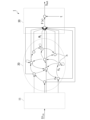
- FIG. 1 is a schematic diagram of an information processing apparatus according to a first embodiment.
- FIG. 2 is a schematic diagram of a reservoir calculation unit according to the first embodiment.
- FIG. 13 is a schematic diagram of another example of a reservoir calculation unit according to the first embodiment. 4 shows a calculation result of the information processing device according to the first embodiment. 13 shows a calculation result of the information processing device according to the first comparative example. 13 is a calculation result of the information processing device according to the second embodiment. 13 shows a calculation result of an information processing device according to a second comparative example.
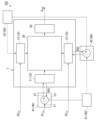
- FIG. 13 is a schematic diagram of an information processing apparatus according to a second embodiment.
- FIG. 13 is a schematic diagram of an information processing apparatus according to a third embodiment.
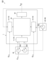
- FIG. 13 is a schematic diagram of an information processing apparatus according to a fourth embodiment.
- FIG. 13 is a schematic diagram of an information processing apparatus according to a fifth embodiment.
- Fig. 1 is a schematic diagram of an information processing device 100 according to a first embodiment.
- the information processing device 100 has, for example, a reservoir calculation unit 1 and a signal control unit 40.
- Fig. 1 illustrates an example in which the signal control unit 40 has a first signal control unit 41 and a second signal control unit 42, but the number of signal control units 40 may be one.
- the reservoir calculation unit 1 is a device that mimics reservoir computing.
- Reservoir computing is one way of realizing a neural network that mimics the human brain. Reservoir computing performs recursive processing by interacting with signals. Reservoir computing, for example, mimics the operation of the cerebellum, and performs recursive data processing and data transformation (for example, coordinate transformation).
- Reservoir computing is one aspect of a recurrent neural network that can handle nonlinear time-series data. Nonlinear time-series data is data whose value changes over time, such as stock prices.
- the reservoir calculation unit 1 has at least one input layer 10, a reservoir layer 20, and an output layer 30.
- the input layer 10 is made up of three layers, a first input layer 11, a second input layer 12, and a third input layer 13, but there may be only one input layer 10.
- the first input layer 11, the second input layer 12, and the third input layer 13 are each connected to a reservoir layer 20.
- a first input signal S1 in is input to the first input layer 11.
- a second input signal S2 in is input to the second input layer 12.
- a third input signal S3 in is input to the third input layer 13.
- the first input signal S1 in , the second input signal S2 in , and the third input signal S3 in may be different signals.
- Each of the first input layer 11, the second input layer 12, and the third input layer 13 is connected to, for example, an input source that generates an input signal.
- the input source is, for example, a voltage source, a current source, a sensor, etc.
- the input signal is, for example, a time series signal.
- the time series signal may be, for example, divided into time domains and input as multiple signals.
- the input signal may be input as is without processing, or may be input after performing Fast Fourier Transform Analysis (FFT analysis).
- FFT analysis extracts frequency characteristics. Furthermore, the FFT analysis can filter out small amplitude signals caused by noise.
- FIG. 2 is a schematic diagram of the reservoir calculation unit 1 according to the first embodiment.
- the first input layer 11, the reservoir layer 20, and the output layer 30 are extracted and illustrated.
- the first input layer 11 is, for example, a single-layer or multi-layer perceptron.
- the first input layer 11 has, for example, a plurality of nodes.
- the first input layer 11 transmits signals input from the outside to the reservoir layer 20.
- the second input layer 12 and the third input layer 13 each have a similar configuration to the first input layer 11.
- FIG. 2 an example is shown in which the first input layer 11 is completely independent of the reservoir layer 20, but as shown in FIG. 3, the first input layer 11 may be part of the reservoir layer 20.
- the first input layer 11 is a collection of nodes n in the reservoir layer 20 to which a signal is first input.
- FIG. 3 is a schematic diagram of another example of the reservoir calculation unit according to the first embodiment.
- the reservoir layer 20 has multiple nodes n that are randomly connected to each other. There is no particular limit to the number of nodes n. The greater the number of nodes n, the greater the expressiveness of the reservoir layer 20.
- Input signals are input to the reservoir layer 20 from each of the input layers 10.
- the reservoir layer 20 stores the input signals.
- the input signals interact with each other within the reservoir layer 20. Signals interact with each other when a signal propagating to a node n affects a signal propagating to another node n. For example, a weight v x is applied to a signal when it propagates between nodes n, causing it to change.
- the reservoir layer 20 projects the input signals into a multidimensional nonlinear space.
- the multiple nodes n When a signal propagates between multiple nodes n, the multiple nodes n generate a feature space that contains information of the signal input to the reservoir layer 20.
- the input signal In the reservoir layer 20, the input signal is replaced by another signal, but at least a part of the information contained in the input signal is retained in a changed form.
- the input signal changes nonlinearly in the reservoir layer 20.
- One example of such a transformation is the replacement from a Cartesian coordinate system (x, y, z) to a spherical coordinate system (r, ⁇ , ⁇ ).
- the state of the system in the reservoir layer 20 changes over time.
- the reservoir layer 20 signals only interact with each other, but do not learn.
- the input signal changes nonlinearly.
- the input signals change over time as they interact with each other in the reservoir layer 20.
- a signal output from a node n at time t may return to the original node n at time t+1.
- Signals at times t and t+1 are input to node n, and the reservoir layer 20 can process information recursively.
- the reservoir layer 20 can process time series signals.
- the weights vx set between the nodes n of the reservoir layer 20 are set in advance.
- the number of weights vx is equal to the number of combinations of connections between the nodes n.
- x is, for example, an arbitrary natural number.
- the weights vx set between the nodes n of the reservoir layer 20 may be changed by learning.
- Each of the nodes n may be replaced by, for example, a physical device.
- the physical device may be, for example, a device that can convert an input signal into vibration, an electromagnetic field, a magnetic field, a spin wave, or the like.
- the node n may be, for example, a MEMS microphone.
- the MEMS microphone can convert the vibration of a diaphragm into an electrical signal.
- the node n may be, for example, a spin torque oscillator (STO).
- STO spin torque oscillator
- the spin torque oscillator can convert an electrical signal into a high-frequency signal.
- the reservoir layer 20 may also be a circuit that performs nonlinear conversion of the input signal.
- the output layer 30 is connected to the reservoir layer 20.
- the output layer 30 may be connected to all or some of the nodes n in the reservoir layer 20.
- the output layer applies a weight wj to each signal sent from the reservoir layer 20.
- the output layer 30 has, for example, a calculation unit, a comparator, and a control unit.
- the calculation unit performs, for example, a multiplication operation in which a weight wj is applied to each signal sent from the reservoir layer 20, and a sum operation in which the results of the product operations are added together.
- the calculation unit may perform an operation in which the product-sum operation result is substituted into the activation function F(x).
- the output layer 30 outputs the calculation result to the outside as an output signal S out .
- the comparator compares the output signal S out with the teacher signal t during learning of the information processing device 100.
- the control unit adjusts the weight wj so that the degree of agreement between the output signal S out and the teacher signal t increases during learning.
- the signal control unit 40 inputs a reflected signal, which is generated when an input signal is input to at least one input layer 10, to one of at least one input layer 10.
- the reflected signal may be input to any one input layer 10, or may be input to multiple input layers 10.
- the first signal control unit 41 inputs a reflected signal RS1 generated when an input signal S1 in is input to the first input layer 11 to the second input layer 12.
- the second signal control unit 42 inputs a reflected signal RS2 generated when an input signal S2 in is input to the second input layer 12 to the third input layer 13.
- the signal control unit 40 includes, for example, a non-reciprocal circuit element that transmits a signal non-reciprocally between the first terminal t1 and the second terminal t2.
- a signal input from the first terminal t1 is transmitted to the second terminal t2 with almost no loss, but a signal input from the second terminal t2 is hardly transmitted to the first terminal t1.
- a circulator is an example of a non-reciprocal circuit element.
- a first input signal S1 in input to the first terminal t1 is transmitted to the second terminal t2 and input to the first input layer 11.
- a reflected signal RS1 generated in the first input layer 11 is input to the second terminal t2 and transmitted to the third terminal t3. Almost no reflected signal RS1 is transmitted from the second terminal t2 to the first terminal t1.
- the reflected signal RS1 is transmitted from the third terminal t3 to the second input layer 12.
- the information processing device 100 performs learning and inference. During learning, the output signal S out is compared with a teacher signal, and a process of changing the weight w j is performed. During inference, a calculation is performed with the set weight w j , and the output signal S out is output as an inference result. In the information processing device 100, the operation up to the output layer 30 is the same during learning and during inference.
- an input signal is input to the information processing device 100.
- a first input signal S1 in is input to the first input layer 11 via the first signal control unit 41.
- a reflected signal RS1 is generated.
- the reflected signal RS1 is input to the second input layer 12 via the first signal control unit 41 and the second signal control unit 42.
- the second input signal S2 in and the reflected signal RS1 are input to the second input layer 12. It takes time for the reflected signal RS1 to arrive at the second input layer 12 after it is generated in the first input layer 11. Therefore, the reflected signal RS1 has information from the past (the time when the reflected signal RS1 was generated in the first input layer 11) when it arrives at the second input layer 12.
- a reflected signal RS2 is generated.
- the reflected signal RS2 is input to the third input layer 13 via the second signal control unit .
- the third input signal S3 in and the reflected signal RS2 are input to the third input layer 13. It takes time for the reflected signal RS2 to arrive at the third input layer 13 after it is generated in the second input layer 12. Therefore, the reflected signal RS2 has information from the past (the time when the reflected signal RS2 was generated in the second input layer 12) when it arrives at the third input layer 13.
- the first input signal S1 in , the second input signal S2 in , the third input signal S3 in , the reflected signal RS1 and the reflected signal RS2 are input to the reservoir layer 20.
- the reflected signals RS1 and RS2 were generated prior to the time when these signals were input to the reservoir layer 20. Therefore, the current first input signal S1 in , the second input signal S2 in and the third input signal S3 in and the reflected signals RS1 and RS2 generated in the past are simultaneously input to the reservoir layer 20.
- the input signal input to the reservoir layer 20 undergoes a nonlinear transformation to generate a feature space containing the information of the input signal.
- the input signal contains information from the current time t and the past time t-1, so the reservoir layer 20 processes the information recursively.
- the signal that has been nonlinearly transformed in the reservoir layer 20 reaches the output layer 30.
- a multiplication operation is performed to apply a weight wj to the signal, and a summation operation is performed to add up the results of the multiplication operations, and an output signal S out is output.
- the information processing device 100 uses the reflected signals RS1 and RS2 as one of the input signals to the reservoir layer 20 without reducing them.
- the reflected signals RS1 and RS2 as one of the input signals to the reservoir layer 20, it is possible to input both current and past information to the reservoir layer 20.
- past information is important.
- the information processing device 100 according to the first embodiment enhances expressiveness by also providing past information to the reservoir layer 20.
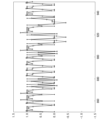
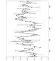
- FIG. 4 shows the calculation results of the information processing device of Example 1
- FIG. 5 shows the calculation results of the information processing device of Comparative Example 1.
- FIG. 4 and FIG. 5 show the results of simulating the calculations of the reservoir calculation unit.
- the solid lines in FIG. 4 and FIG. 5 are teacher signals, and the dotted lines are the output results from the information processing device.
- the teacher signal is the previous input value, and this task makes it possible to check whether past information is being retained.
- Example 1 and Comparative Example 1 it was assumed that 70% of the input signal was generated as a reflected signal.
- all input signals S all (t) input at a certain time S(t).
- all input signals include reflected signals
- Comparative Example 1 all input signals do not include reflected signals.
- the random number of the value that the teacher signal can take was set to 0 or 1.
- Example 1 matches the teacher signal better than the comparative example 1. This is thought to be because the expressive power of the information processing device 100 is improved by inputting past information in the form of a reflected signal to the reservoir layer.
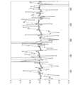
- FIG. 6 shows the calculation results of the information processing device of Example 2
- FIG. 7 shows the calculation results of the information processing device of Comparative Example 2.
- FIGS. 6 and 7 show the results of simulating the calculations of the reservoir calculation unit.
- the solid lines in FIGS. 6 and 7 show the teacher signal, and the dotted lines show the output results from the information processing device.
- Example 2 and Comparative Example 2 differ from Example 1 and Comparative Example 1, respectively, in that the random numbers that the teacher signal can take are in the range of -1 to 1.
- Example 2 matches the teacher signal better than the comparative example 2. Similar results were obtained even when the random numbers were changed.
- Second Embodiment 8 is a schematic diagram of an information processing device 101 according to the second embodiment.
- the information processing device 101 differs from the information processing device 100 in that it further includes a signal delay unit 50.
- the same components as those in the information processing device 100 are denoted by the same reference numerals, and description thereof will be omitted.
- the signal delay unit 50 has a first signal delay unit 51 and a second signal delay unit 52, but there may be only one signal delay unit 50.
- the signal delay unit 50 delays the reflected signal.
- the first signal delay unit 51 delays the reflected signal RS1.
- the second signal delay unit 52 delays the reflected signal RS2.
- the first signal delay unit 51 is, for example, between the first signal control unit 41 and the second signal control unit 42.
- the second signal delay unit 52 is, for example, between the second signal control unit 42 and the third input layer 13.
- the signal delay unit 50 can be any device capable of delaying a signal.
- the signal delay unit 50 can be an elastic wave conversion element, a memory element, a delay circuit, or a sample and hold circuit.
- An elastic wave conversion element is an element that converts an electrical signal into an elastic wave.
- Examples of elastic wave conversion elements are surface acoustic wave filters, piezoelectric elements, and magnetostrictive elements.
- a surface acoustic wave filter converts an electrical signal into a surface wave.
- a surface acoustic wave filter is an example of a piezoelectric element, but elastic waves are not limited to surface waves. Because elastic waves propagate slower than electromagnetic fields, converting an electrical signal into an elastic wave causes a delay in the signal.
- a memory element is an element that can store electrical signals. If the reflected signal is temporarily stored in the memory element and then output after a certain period of time has passed, a delay will occur in the signal.
- the information processing device 101 inputs the reflected signals RS1 and RS2 to the reservoir layer 20, and therefore has the same effect as the information processing device 100 according to the first embodiment.
- the signal delay unit 50 it becomes possible to input older information to the reservoir layer 20, thereby enhancing the expressive power of the information processing device 101.
- “Third embodiment” 9 is a schematic diagram of an information processing device 102 according to the third embodiment.
- the information processing device 102 differs from the information processing device 100 in that it further includes a signal intensity adjustment unit 60.
- the same components as those in the information processing device 100 are denoted by the same reference numerals, and description thereof will be omitted.
- the signal intensity adjustment unit 60 has a first signal intensity adjustment unit 61 and a second signal intensity adjustment unit 62, but there may be only one signal intensity adjustment unit 60.
- the signal intensity adjustment unit 60 adjusts the intensity of the reflected signal.
- the first signal intensity adjustment unit 61 adjusts the intensity of the reflected signal RS1.
- the second signal intensity adjustment unit 62 adjusts the intensity of the reflected signal RS2.
- the first signal intensity adjustment unit 61 is, for example, between the first signal control unit 41 and the second signal control unit 42.
- the second signal intensity adjustment unit 62 is, for example, between the second signal control unit 42 and the third input layer 13.
- the signal strength adjustment unit 60 can be any device that can change the strength of a signal.
- the signal strength adjustment unit 60 can be an amplifier, an attenuator, or a matching circuit.
- the amplifier is, for example, an operational amplifier.
- the attenuator is, for example, a circuit component composed of resistive elements.
- the matching circuit is a circuit that matches the impedance between a first circuit that sends out a signal and a second circuit that receives the signal.
- the matching circuit is provided, for example, before the first input layer 11 where signal reflection occurs.
- the information processing device 102 inputs the reflected signals RS1 and RS2 to the reservoir layer 20, and therefore has the same effect as the information processing device 100 according to the first embodiment.
- the signal intensity adjustment unit 60 it is possible to adjust how much past information is input to the reservoir layer 20, and the information processing device 102 can perform processing suited to the task.
- “Fourth embodiment” 10 is a schematic diagram of an information processing device 103 according to a fourth embodiment.
- the information processing device 103 differs from the information processing device 100 in that it further includes a signal delay unit 50 and a signal intensity adjustment unit 60.
- the same components as those in the information processing device 100 are denoted by the same reference numerals, and description thereof will be omitted.
- the signal delay unit 50 is the same as that of the information processing device 101 according to the second embodiment.
- the signal intensity adjustment unit 60 is the same as that of the information processing device 102 according to the third embodiment.
- the information processing device 103 inputs the reflected signals RS1 and RS2 to the reservoir layer 20, and therefore has the same effect as the information processing device 100 according to the first embodiment.
- the reflected signals RS1 and RS2 input to the reservoir layer 20 can be freely designed.
- Fifth embodiment 11 is a schematic diagram of an information processing device 104 according to the fifth embodiment.
- the information processing device 104 differs from the information processing device 100 in the configuration of the signal control unit 45.
- the same components as those in the information processing device 100 are denoted by the same reference numerals, and the description thereof will be omitted.
- the information processing device 104 has, for example, a reservoir calculation unit 1 and a signal control unit 45.
- the signal control unit 45 re-inputs a reflected signal RS1 generated when an input signal is input to the first input layer 11 to the first input layer 11, and also inputs the reflected signal to the second signal control unit 42.
- the signal control unit 45 includes, for example, two irreversible circuit elements.
- the irreversible circuit elements are, for example, circulators.
- the first input signal S1 in is input to the first input layer 11 via the signal control unit 45.
- a reflected signal RS1 is generated when the first input signal S1 in is input to the first input layer 11.
- the reflected signal RS1 is re-input to the first input layer 11 via the signal control unit 45. Then, the reflected signal re-reflected by the first input layer 11 is input to the second signal control unit 42.
- the reflected signal RS1 generated when an input signal is input to the first input layer 11 is re-input to the first input layer 11 and also input to the second signal control unit 42, but it may also be re-input only to the first input layer 11.
- the information processing device 104 inputs the reflected signal RS1 to the reservoir layer 20, and therefore achieves the same effects as the information processing device 100 according to the first embodiment.
- the information processing device according to the present invention is not limited to these.
Landscapes
- Engineering & Computer Science (AREA)
- Theoretical Computer Science (AREA)
- Physics & Mathematics (AREA)
- Data Mining & Analysis (AREA)
- General Health & Medical Sciences (AREA)
- Biomedical Technology (AREA)
- Biophysics (AREA)
- Computational Linguistics (AREA)
- Life Sciences & Earth Sciences (AREA)
- Evolutionary Computation (AREA)
- Artificial Intelligence (AREA)
- Molecular Biology (AREA)
- Computing Systems (AREA)
- General Engineering & Computer Science (AREA)
- General Physics & Mathematics (AREA)
- Mathematical Physics (AREA)
- Software Systems (AREA)
- Health & Medical Sciences (AREA)
- Testing Or Calibration Of Command Recording Devices (AREA)
Abstract
本実施形態に係る情報処理装置は、少なくとも一つの入力層と、レザバー層と、出力層と、を備える。前記少なくとも一つの入力層は、レザバー層に接続されている。前記レザバー層は、前記レザバー層に入力された入力信号の情報を含む特徴空間を生成する。前記出力層は、前記レザバー層に接続され、前記レザバー層から送られる信号のそれぞれに重みを印加する。この情報処理装置は、前記少なくとも一つの入力層に入力信号が入力された際に生じる反射信号を、前記少なくとも一つの入力層のいずれかに入力する。
Description
本発明は、情報処理装置に関する。
近年、データを分散処理するエッジコンピューティングに注目が集まっている。エッジコンピューティングは、データをクラウドで集中処理するクラウドコンピューティングに対向する概念である。エッジコンピューティングは、クラウドコンピューティングのような大規模サーバーが不要であり、ネットワーク負荷を低減でき、セキュリティーの強化が容易であるという特徴を有する。
レザバーコンピューティングは、エッジコンピューティングを担うエッジ端末への利用が期待されている。レザバーコンピューティングは、ニューラルネットワークの1種であり、例えば、小脳の動作を模倣する。レザバーコンピューティングは、信号を相互作用させることで、再帰的な処理を行う。
ソフトウェアを用いてニューラルネットワークを処理すると、十分な処理効率が得られない場合があり、ニューラルネットワークに特化したデバイスが提案されている。例えば、特許文献1には振動子を用いたレザバー演算装置が開示されている。
レザバーには入力信号が入力される。入力信号が入力される入力路とレザバーとは、状態が異なり特性インピーダンスも異なるため、入力信号の一部は反射する。特許文献1に記載のレザバー演算装置は、入力を終端するためのマッチング回路を設け、反射信号を低減している。
マッチング回路は、入力信号が特定の周波数の際には効果を示すが、周波数が変化した場合、入力信号が広帯域な場合は、反射信号を十分に低減することができない。
本開示は上記事情に鑑みてなされたものであり、反射信号を利用して、レザバーに再入力させることで、表現力に優れた情報処理装置を提供することを目的とする。
第1の態様にかかる情報処理装置は、少なくとも一つの入力層と、レザバー層と、出力層と、を備える。前記少なくとも一つの入力層は、レザバー層に接続されている。前記レザバー層は、前記レザバー層に入力された入力信号の情報を含む特徴空間を生成する。前記出力層は、前記レザバー層に接続され、前記レザバー層から送られる信号のそれぞれに重みを印加する。この情報処理装置は、前記少なくとも一つの入力層に入力信号が入力された際に生じる反射信号を、前記少なくとも一つの入力層のいずれかに入力する。
上記態様にかかる情報処理装置は、反射信号を利用して、レザバーに再入力させることで、表現力に優れる。
以下、本実施形態について、図を適宜参照しながら詳細に説明する。以下の説明で用いる図面は、本発明の特徴をわかりやすくするために便宜上特徴となる部分を拡大して示している場合があり、各構成要素の寸法比率などは実際とは異なっていることがある。以下の説明において例示される材料、寸法等は一例であって、本発明はそれらに限定されるものではなく、本発明の効果を奏する範囲で適宜変更して実施することが可能である。
「第1実施形態」
図1は、第1実施形態に係る情報処理装置100の模式図である。情報処理装置100は、例えば、レザバー計算部1と信号制御部40とを有する。図1では、信号制御部40が第1信号制御部41と第2信号制御部42とを有する例を例示するが、信号制御部40は一つでもよい。
図1は、第1実施形態に係る情報処理装置100の模式図である。情報処理装置100は、例えば、レザバー計算部1と信号制御部40とを有する。図1では、信号制御部40が第1信号制御部41と第2信号制御部42とを有する例を例示するが、信号制御部40は一つでもよい。
レザバー計算部1は、レザバーコンピューティングを模倣したデバイスである。レザバーコンピューティングは、人間の脳を模倣したニューラルネットワークを実現する一つの手段である。レザバーコンピューティングは、信号を相互作用させることで、再帰的な処理を行う。レザバーコンピューティングは、例えば、小脳の動作を模倣しており、再帰的なデータの処理やデータの変換(例えば、座標の変換)等を行う。レザバーコンピューティングは、非線形な時系列のデータを扱うことができるリカレントニューラルネットワークの一態様である。非線形な時系列のデータは、時間の経過とともに値が変化するデータであり、株価等はその一例である。
レザバー計算部1は、少なくとも一つの入力層10とレザバー層20と出力層30とを備える。図1では、入力層10が第1入力層11と第2入力層12と第3入力層13の3つからなる例を示すが、入力層10は、一つでもよい。
第1入力層11と第2入力層12と第3入力層13のそれぞれは、レザバー層20に接続されている。第1入力層11には、第1入力信号S1inが入力される。第2入力層12には、第2入力信号S2inが入力される。第3入力層13には、第3入力信号S3inが入力される。第1入力信号S1inと第2入力信号S2inと第3入力信号S3inとは、異なる信号でもよい。様々な信号がレザバー層20に入力されることで、情報処理装置100の表現力が高まる。
第1入力層11と第2入力層12と第3入力層13のそれぞれは、例えば、入力信号を生み出す入力源に接続されている。入力源は、例えば、電圧源、電流源、センサー等である。入力信号は、例えば、時系列信号である。時系列信号は、例えば、タイムドメイン毎に分割し、複数の信号として入力してもよい。入力信号は、処理せずにそのまま入力してもよいが、Fast Fourier Transform Analysis (FFT analysis)を行った後の信号を入力してもよい。FFT analysisは、周波数の特徴を抽出する。また、FFT analysisは、ノイズに起因する小さい振幅の信号をフィルタリングできる。
図2は、第1実施形態に係るレザバー計算部1の模式図である。図2では、第1入力層11とレザバー層20と出力層30とを抽出して図示している。
第1入力層11は、例えば、単層又は多層のパーセプトロンである。第1入力層11は、例えば、複数のノードを有する。第1入力層11は、外部から入力された信号をレザバー層20に伝える。第2入力層12と第3入力層13のそれぞれは、第1入力層11と同様の構成を有する。
図2では、第1入力層11がレザバー層20と完全に独立である例を示したが、図3に示すように、第1入力層11はレザバー層20の一部でもよい。この場合、第1入力層11は、レザバー層20内のノードnのうち最初に信号が入力されるノードnの集合体である。図3は、第1実施形態に係るレザバー計算部の別の例の模式図である。
レザバー層20は、互いにランダムに接続された複数のノードnを有する。ノードnの数は、特に問わない。ノードnの数が多いほど、レザバー層20の表現力は高まる。
レザバー層20には入力層10のそれぞれから入力信号が入力される。レザバー層20は、入力された入力信号を貯留する。入力された信号は、レザバー層20内で、互いに相互作用する。信号が相互作用するとは、あるノードnに伝搬した信号が他のノードnを伝搬する信号に影響を及ぼすことをいう。例えば、信号は、ノードn間を伝搬する際に重みvxが印加され、変化していく。レザバー層20は、入力された信号を多次元の非線形空間に射影する。
信号が複数のノードn間を伝搬すると、複数のノードnは、レザバー層20に入力された信号の情報を含む特徴空間を生成する。レザバー層20内おいて、入力された信号は、別の信号に置き換わるが、入力された信号に含まれる情報の少なくとも一部は形を変えて保有される。入力された信号は、レザバー層20内において非線形に変化する。当該変換の一例として、直交座標系(x,y,z)から球面座標系(r,θ,φ)への置き換えが挙げられる。入力された信号がレザバー層20内で相互作用することで、レザバー層20の系の状態は、時間の経過とともに変化する。
レザバー層20内では、信号は相互作用するだけであり、学習しない。レザバー層20内で信号が互いに相互作用すると、入力信号が非線形に変化する。また入力信号は、レザバー層20内で互いに相互作用することで、時間の経過とともに変化する。またレザバー層20内において、あるノードnからある時刻tに出力された信号は、元のノードnに時刻t+1において戻る場合がある。ノードnには、時刻t及び時刻t+1の信号が入力され、レザバー層20は情報を再帰的に処理できる。レザバー層20は、時系列信号を処理できる。
レザバー層20のノードn間に設定される重みvxは、事前に設定される。重みvxの数は、ノードn間の接続の組み合わせの数だけある。xは、例えば、任意の自然数である。レザバー層20のノードn間に設定される重みvxは、学習により変動してもよい。
ノードnのそれぞれは、例えば、物理的なデバイスに置き換えられる。物理デバイスは、例えば、入力された信号を振動、電磁場、磁場、スピン波等に変換できるデバイスである。ノードnは、例えば、MEMSマイクロフォンである。MEMSマイクロフォンは、振動膜の振動を電気信号に変換することができる。ノードnは、例えば、スピントルクオシレータ(STO)でもよい。スピントルクオシレータは、電気信号を高周波信号に変換することができる。またレザバー層20は、入力信号を非線形変換する回路でもよい。
出力層30は、レザバー層20に接続されている。出力層30は、レザバー層20内の全てのノードnと接続していてもよいし、一部のノードnと接続していてもよい。出力層は、レザバー層20から送られる信号のそれぞれに重みwjを印加する。
出力層30は、例えば、演算部と比較器と制御部とを有する。演算部は、例えば、レザバー層20から送られる信号のそれぞれに重みwjを印加する積演算と、積演算結果を足し合わせる和演算とを行う。演算部は、積和演算結果を活性化関数F(x)に代入する演算を行ってもよい。出力層30は、演算結果を外部に出力信号Soutとして出力する。比較器は、情報処理装置100の学習時において、出力信号Soutと教師信号tとの比較を行う。制御部は、学習時において、出力信号Soutと教師信号tとの一致度が高くなるように、重みwjを調整する。
信号制御部40は、少なくとも一つの入力層10に入力信号が入力された際に生じる反射信号を、少なくとも一つの入力層10のいずれかに入力する。反射信号は、いずれか一つの入力層10に入力してもよいし、複数の入力層10に入力してもよい。
第1信号制御部41は、第1入力層11に入力信号S1inが入力された際に生じる反射信号RS1を第2入力層12に入力する。第2信号制御部42は、第2入力層12に入力信号S2inが入力された際に生じる反射信号RS2を第3入力層13に入力する。
信号制御部40は、例えば、第1端子t1と第2端子t2との間で信号を非可逆に伝送する非可逆回路素子を含む。第1端子t1から入力された信号は、第2端子t2にほとんどロスなく伝送されるが、第2端子t2から入力された信号は、第1端子t1にはほとんど伝送されない。サーキュレーターは、非可逆回路素子の一例である。
例えば第1信号制御部41において、第1端子t1に入力された第1入力信号S1inは、第2端子t2に伝送され、第1入力層11に入力される。第1入力層11で生じた反射信号RS1は、第2端子t2に入力され、第3端子t3に伝送される。反射信号RS1は、第2端子t2から第1端子t1へはほとんど伝送されない。反射信号RS1は、第3端子t3から第2入力層12へ伝送される。
次いで、第1実施形態に係る情報処理装置100の動作について説明する。情報処理装置100は、学習と推論とを行う。学習時は、出力信号Soutと教師信号とを比較して、重みwjを変更する処理を行う。推論時は、設定された重みwjで演算を行い、出力信号Soutを推論結果として出力する。情報処理装置100において、出力層30に至るまでの動作は、学習時でも推論時でも同様である。
まず情報処理装置100に入力信号が入力される。例えば、第1入力信号S1inは、第1信号制御部41を介して、第1入力層11に入力される。第1入力層11に第1入力信号S1inが入力される際に反射信号RS1が生じる。反射信号RS1は、第1信号制御部41及び第2信号制御部42を介して、第2入力層12に入力される。
第2入力層12には、第2入力信号S2inと反射信号RS1とが入力される。反射信号RS1が第1入力層11で生じ、第2入力層12に至るまでに時間がかかる。そのため、反射信号RS1は、第2入力層12に到達した時点で、過去(反射信号RS1が第1入力層11で生じた時点)の情報を持つ。
また第2入力層12に第2入力信号S2inが入力される際には、反射信号RS2が生じる。反射信号RS2は、第2信号制御部42を介して、第3入力層13に入力される。
第3入力層13には、第3入力信号S3inと反射信号RS2とが入力される。反射信号RS2が第2入力層12で生じ、第3入力層13に至るまでに時間がかかる。そのため、反射信号RS2は、第3入力層13に到達した時点で、過去(反射信号RS2が第2入力層12で生じた時点)の情報を持つ。
第1入力信号S1in、第2入力信号S2in、第3入力信号S3in、反射信号RS1及び反射信号RS2は、レザバー層20に入力される。反射信号RS1及び反射信号RS2は、これらの信号がレザバー層20に入力される時点より過去に発生している。そのため、レザバー層20には、現在の第1入力信号S1in、第2入力信号S2in及び第3入力信号S3inと、過去に発生した反射信号RS1及び反射信号RS2が同時に入力される。
レザバー層20内では、レザバー層20に入力された入力信号が非線形変換し、入力信号の情報を含む特徴空間を生成する。入力信号は、現在の時刻tと過去の時刻t-1の情報が入力されるため、レザバー層20は情報を再帰的に処理する。
レザバー層20で非線形変換された信号は、出力層30に至る。出力層30では、信号に重みwjを印加する積演算と、積演算結果を足し合わせる和演算と、が行われ、出力信号Soutが出力される。
上述のように、第1実施形態に係る情報処理装置100は、反射信号RS1、RS2を低減せずに、レザバー層20への入力信号の一つとして用いている。反射信号RS1、RS2をレザバー層20への入力信号の一つとすることで、レザバー層20に現在及び過去の情報を合わせて入力することができる。例えば、過去の情報に基づいて変動する時系列信号を処理する際は、過去の情報は重要である。第1実施形態に係る情報処理装置100は、レザバー層20に過去の情報も与えることで、表現力が高まる。
図4は、実施例1に係る情報処理装置の演算結果であり、図5は、比較例1に係る情報処理装置の演算結果である。図4及び図5は、レザバー計算部の演算をシミュレーションした結果である。図4及び図5における実線は教師信号であり、点線は情報処理装置からの出力結果である。教師信号は一つ前の入力値であり、このタスクによって、過去の情報を保持できているか否かを確認できる。
実施例1及び比較例1では、反射信号として入力信号の70%の信号が生じていると仮定した。実施例1は、ある時刻に入力される全入力信号Sall(t)をSall(t)=S(t)+S(t-1)×0.7+S(t-2)×0.7×0.7+S(t-3)×0.7×0.7×0.7+…とした。実施例2は、ある時刻に入力される全入力信号Sall(t)をSall(t)=S(t)とした。実施例1は、全入力信号が反射信号を含んでいるのに対し、比較例1は、全入力信号が反射信号を含んでいない。実施例1及び比較例1では、教師信号が取りうる値の乱数を0又は1とした。
図4と図5との結果を比較すると分かるように、実施例1は教師信号に対する出力信号の一致度が比較例1より高い。これは、反射信号という形で過去の情報をレザバー層に入力することで、情報処理装置100の表現力が高まったためと考えられる。
図6は、実施例2に係る情報処理装置の演算結果であり、図7は、比較例2に係る情報処理装置の演算結果である。図6及び図7は、レザバー計算部の演算をシミュレーションした結果である。図6及び図7における実線は教師信号であり、点線は情報処理装置からの出力結果である。実施例2及び比較例2では、教師信号が取りうる値の乱数を-1から1の範囲とした点が、実施例1及び比較例1のそれぞれと異なる。
図6と図7との結果を比較すると分かるように、実施例2は教師信号に対する出力信号の一致度が比較例2より高い。乱数を変えても同様の結果が得られた。
「第2実施形態」
図8は、第2実施形態に係る情報処理装置101の模式図である。情報処理装置101は、信号遅延部50をさらに備える点が、情報処理装置100と異なる。情報処理装置101において、情報処理装置100と同様の構成には同様の符号を付し、説明を省く。
図8は、第2実施形態に係る情報処理装置101の模式図である。情報処理装置101は、信号遅延部50をさらに備える点が、情報処理装置100と異なる。情報処理装置101において、情報処理装置100と同様の構成には同様の符号を付し、説明を省く。
図8では、信号遅延部50が第1信号遅延部51と第2信号遅延部52とを有する例を例示するが、信号遅延部50は一つでもよい。信号遅延部50は、反射信号を遅延させる。第1信号遅延部51は、反射信号RS1を遅延させる。第2信号遅延部52は、反射信号RS2を遅延させる。
第1信号遅延部51は、例えば、第1信号制御部41と第2信号制御部42との間にある。第2信号遅延部52は、例えば、第2信号制御部42と第3入力層13との間にある。
信号遅延部50は、信号を遅延させることができるものであれば、特に問わない。信号遅延部50は、例えば、弾性波変換素子、記憶素子、遅延回路、サンプルアンドホールド回路である。
弾性波変換素子は、電気信号を弾性波に変換する素子である。弾性波変換素子は、例えば、表面弾性波フィルター、圧電素子、磁歪素子である。表面弾性波フィルターは、電気信号を表面波に変換する。表面弾性波フィルターは、圧電素子の一例でもあるが、弾性波は表面波に限られない。弾性波は電磁場より伝搬速度が遅いため、電気信号を弾性波に変えることで信号に遅延が生じる。
記憶素子は、電気信号を記憶できる素子である。反射信号を記憶素子に一旦記憶させ、一定時間経過後に出力すると、信号に遅延が生じる。
第2実施形態に係る情報処理装置101は、反射信号RS1、RS2をレザバー層20に入力するため、第1実施形態に係る情報処理装置100と同様の効果を奏する。また信号遅延部50を用いることで、より過去の情報をレザバー層20に入力することが可能となり、情報処理装置101の表現力が高まる。
「第3実施形態」
図9は、第3実施形態に係る情報処理装置102の模式図である。情報処理装置102は、信号強度調整部60をさらに備える点が、情報処理装置100と異なる。情報処理装置102において、情報処理装置100と同様の構成には同様の符号を付し、説明を省く。
図9は、第3実施形態に係る情報処理装置102の模式図である。情報処理装置102は、信号強度調整部60をさらに備える点が、情報処理装置100と異なる。情報処理装置102において、情報処理装置100と同様の構成には同様の符号を付し、説明を省く。
図9では、信号強度調整部60が第1信号強度調整部61と第2信号強度調整部62とを有する例を例示するが、信号強度調整部60は一つでもよい。信号強度調整部60は、反射信号の強度を調整する。第1信号強度調整部61は、反射信号RS1の強度を調整する。第2信号強度調整部62は、反射信号RS2の強度を調整する。
第1信号強度調整部61は、例えば、第1信号制御部41と第2信号制御部42との間にある。第2信号強度調整部62は、例えば、第2信号制御部42と第3入力層13との間にある。
信号強度調整部60は、信号の強度を変更できるものであれば、特に問わない。信号強度調整部60は、例えば、増幅器、減衰器、整合回路である。
増幅器は、例えば、オペアンプである。減衰器は、例えば、抵抗素子で構成された回路部品である。整合回路は、信号を送り出す側の第1回路と信号を受け取る側の第2回路との間のインピーダンスを整合する回路である。整合回路は、例えば、信号の反射が発生する第1入力層11の手前に設けられる。インピーダンスの整合の程度を変えることで、信号強度調整部60に入力された信号に対する信号強度調整部60から反射する信号の強度比を変えることができる。
第3実施形態に係る情報処理装置102は、反射信号RS1、RS2をレザバー層20に入力するため、第1実施形態に係る情報処理装置100と同様の効果を奏する。また信号強度調整部60を用いることで、よりどの程度過去の情報をレザバー層20に入力するかを調整することができ、情報処理装置102がタスクに合わせた処理を行うことができる。
「第4実施形態」
図10は、第4実施形態に係る情報処理装置103の模式図である。情報処理装置103は、信号遅延部50及び信号強度調整部60をさらに備える点が、情報処理装置100と異なる。情報処理装置103において、情報処理装置100と同様の構成には同様の符号を付し、説明を省く。
図10は、第4実施形態に係る情報処理装置103の模式図である。情報処理装置103は、信号遅延部50及び信号強度調整部60をさらに備える点が、情報処理装置100と異なる。情報処理装置103において、情報処理装置100と同様の構成には同様の符号を付し、説明を省く。
信号遅延部50は、第2実施形態に係る情報処理装置101と同様である。信号強度調整部60は、第3実施形態に係る情報処理装置102と同様である。
第4実施形態に係る情報処理装置103は、反射信号RS1、RS2をレザバー層20に入力するため、第1実施形態に係る情報処理装置100と同様の効果を奏する。また信号遅延部50及び信号強度調整部60を有することで、レザバー層20に入力される反射信号RS1、RS2を自由に設計できる。
「第5実施形態」
図11は、第5実施形態に係る情報処理装置104の模式図である。情報処理装置104は、信号制御部45の構成が、情報処理装置100と異なる。情報処理装置104において、情報処理装置100と同様の構成には同様の符号を付し、説明を省く。
図11は、第5実施形態に係る情報処理装置104の模式図である。情報処理装置104は、信号制御部45の構成が、情報処理装置100と異なる。情報処理装置104において、情報処理装置100と同様の構成には同様の符号を付し、説明を省く。
情報処理装置104は、例えば、レザバー計算部1と信号制御部45とを有する。
信号制御部45は、第1入力層11に入力信号が入力された際に生じる反射信号RS1を、第1入力層11に再入力し、かつ、第2信号制御部42に入力する。信号制御部45は、例えば、2つの不可逆回路素子を備える。不可逆回路素子は、例えば、サーキュレーターである。第1入力信号S1inは、信号制御部45を介して、第1入力層11に入力される。第1入力層11に第1入力信号S1inが入力される際に反射信号RS1が生じる。反射信号RS1は、信号制御部45を介して、第1入力層11に再入力される。そして、第1入力層11で再反射した反射信号が、第2信号制御部42に入力する。
ここでは、第1入力層11に入力信号が入力された際に生じる反射信号RS1を、第1入力層11に再入力し、かつ、第2信号制御部42に入力する例を示したが、第1入力層11にのみ再入力してもよい。
第5実施形態に係る情報処理装置104は、反射信号RS1をレザバー層20に入力するため、第1実施形態に係る情報処理装置100と同様の効果を奏する。
以上、いくつかの実施形態を用いて情報処理装置の例を提示したが、本発明に係る情報処理装置はこれらに限られるものではない。例えば、それぞれの実施形態における特徴的な構成をそれぞれ組み合わせることができる。
1 レザバー計算部
10 入力層
11 第1入力層
12 第2入力層
13 第3入力層
20 レザバー層
30 出力層
40、45 信号制御部
41 第1信号制御部
42 第2信号制御部
50 信号遅延部
51 第1信号遅延部
52 第2信号遅延部
60 信号強度調整部
61 第1信号強度調整部
62 第2信号強度調整部
100、101、102、103、104 情報処理装置
RS1、RS2 反射信号
S1in 第1入力信号
S2in 第2入力信号
S3in 第3入力信号
Sout 出力信号
10 入力層
11 第1入力層
12 第2入力層
13 第3入力層
20 レザバー層
30 出力層
40、45 信号制御部
41 第1信号制御部
42 第2信号制御部
50 信号遅延部
51 第1信号遅延部
52 第2信号遅延部
60 信号強度調整部
61 第1信号強度調整部
62 第2信号強度調整部
100、101、102、103、104 情報処理装置
RS1、RS2 反射信号
S1in 第1入力信号
S2in 第2入力信号
S3in 第3入力信号
Sout 出力信号
Claims (10)
- 少なくとも一つの入力層と、レザバー層と、出力層と、を備え、
前記少なくとも一つの入力層は、レザバー層に接続され、
前記レザバー層は、前記レザバー層に入力された入力信号の情報を含む特徴空間を生成し、
前記出力層は、前記レザバー層に接続され、前記レザバー層から送られる信号のそれぞれに重みを印加し、
前記少なくとも一つの入力層に入力信号が入力された際に生じる反射信号を、前記少なくとも一つの入力層のいずれかに入力する、情報処理装置。 - 前記反射信号は、第1入力層に入力信号が入力された際に生じ、
前記反射信号を前記第1入力層に再入力する、請求項1に記載の情報処理装置。 - 前記少なくとも一つの入力層は、複数の入力層であり、
前記反射信号は、第1入力層に入力信号が入力された際に生じ、
前記反射信号を前記第1入力層と異なる第2入力層に入力する、請求項1に記載の情報処理装置。 - 信号制御部をさらに備え、
前記信号制御部は、前記反射信号を制御し、前記少なくとも一つの入力層のいずれかに入力する、請求項1に記載の情報処理装置。 - 前記信号制御部は、第1端子と第2端子との間で信号を非可逆に伝送する非可逆回路素子を含む、請求項4に記載の情報処理装置。
- 信号遅延部をさらに備え、
前記信号遅延部は、前記反射信号を遅延させる、請求項1に記載の情報処理装置。 - 前記信号遅延部は、電気信号を弾性波に変換する弾性波変換素子を備える、請求項6に記載の情報処理装置。
- 前記信号遅延部は、前記反射信号を一定期間保持する記憶素子を備える、請求項6に記載の情報処理装置。
- 信号強度調整部をさらに備え、
前記信号強度調整部は、前記反射信号の強度を調整する、請求項1に記載の情報処理装置。 - 前記信号強度調整部は、前記信号強度調整部に入力された信号を送り出す側の第1回路と前記信号を受け取る側の第2回路との間のインピーダンスを整合する整合回路を備える、請求項9に記載の情報処理装置。
Priority Applications (2)
| Application Number | Priority Date | Filing Date | Title |
|---|---|---|---|
| JP2025501962A JPWO2024176334A1 (ja) | 2023-02-21 | 2023-02-21 | |
| PCT/JP2023/006176 WO2024176334A1 (ja) | 2023-02-21 | 2023-02-21 | 情報処理装置 |
Applications Claiming Priority (1)
| Application Number | Priority Date | Filing Date | Title |
|---|---|---|---|
| PCT/JP2023/006176 WO2024176334A1 (ja) | 2023-02-21 | 2023-02-21 | 情報処理装置 |
Publications (1)
| Publication Number | Publication Date |
|---|---|
| WO2024176334A1 true WO2024176334A1 (ja) | 2024-08-29 |
Family
ID=92500411
Family Applications (1)
| Application Number | Title | Priority Date | Filing Date |
|---|---|---|---|
| PCT/JP2023/006176 Ceased WO2024176334A1 (ja) | 2023-02-21 | 2023-02-21 | 情報処理装置 |
Country Status (2)
| Country | Link |
|---|---|
| JP (1) | JPWO2024176334A1 (ja) |
| WO (1) | WO2024176334A1 (ja) |
Citations (1)
| Publication number | Priority date | Publication date | Assignee | Title |
|---|---|---|---|---|
| US20200131025A1 (en) * | 2017-06-15 | 2020-04-30 | Cymatics Laboratories Corp. | Wave propagation computing devices for machine learning |
-
2023
- 2023-02-21 JP JP2025501962A patent/JPWO2024176334A1/ja active Pending
- 2023-02-21 WO PCT/JP2023/006176 patent/WO2024176334A1/ja not_active Ceased
Patent Citations (1)
| Publication number | Priority date | Publication date | Assignee | Title |
|---|---|---|---|---|
| US20200131025A1 (en) * | 2017-06-15 | 2020-04-30 | Cymatics Laboratories Corp. | Wave propagation computing devices for machine learning |
Also Published As
| Publication number | Publication date |
|---|---|
| JPWO2024176334A1 (ja) | 2024-08-29 |
Similar Documents
| Publication | Publication Date | Title |
|---|---|---|
| Lekutai | Adaptive self-tuning neuro wavelet network controllers | |
| Zhang et al. | A complex-valued projection neural network for constrained optimization of real functions in complex variables | |
| Wang et al. | Fault estimation filter design for discrete‐time descriptor systems | |
| Ichimura et al. | A numerical exploration of signal detector arrangement in a spin-wave reservoir computing device | |
| Zhang et al. | Convergence analysis of fully complex backpropagation algorithm based on Wirtinger calculus | |
| Glyzin et al. | Multistability and bursting in a pair of delay coupled oscillators with a relay nonlinearity | |
| Arunkumar et al. | State estimation for switched discrete-time stochastic BAM neural networks with time varying delay | |
| Diaz et al. | Spike-based compact digital neuromorphic architecture for efficient implementation of high order FIR filters | |
| Faraji et al. | Deep independent recurrent neural network technique for modeling transient behavior of nonlinear circuits | |
| Tiwari et al. | Lie symmetry analysis, optimal system and exact solutions of a new (2+ 1)-dimensional KdV equation | |
| Zhou et al. | Sparsity‐optimised farrow structure variable fractional delay filter for wideband array | |
| WO2022201425A1 (ja) | 情報処理装置、隠れノードの設定方法及び情報処理装置の製造方法 | |
| Joshi et al. | n-th-order simple hyperjerk system with unstable equilibrium and its application as RPG | |
| Liu et al. | Hardware spiking neural networks with pair-based STDP using stochastic computing | |
| Bhalekar | Analysing the stability of a delay differential equation involving two delays | |
| Hirose et al. | Relationship between phase and amplitude generalization errors in complex-and real-valued feedforward neural networks | |
| US20230419094A1 (en) | Reservoir element | |
| Arjunan et al. | Existence and controllability results for damped second order impulsive functional differential systems with state-dependent delay | |
| Mengüç | Adaptive Fourier linear combiner based on modified least mean Kurtosis algorithm for the processing of sinusoidal signals | |
| Akraminia et al. | Feedforward active noise control using wavelet frames: simulation and experimental results | |
| Perkins | Noise-enhanced learning in Duffing adaptive oscillator | |
| Akhmet et al. | A Hopfield neural network with multi-compartmental activation | |
| Yang et al. | Synchronization of discontinuous neural networks with delays via adaptive control | |
| JP6908210B1 (ja) | パラメータの設定方法およびリザボア素子の制御方法 | |
| Prasanna Kumar et al. | Adaptive filter algorithms based noise cancellation using neural network in mobile applications |
Legal Events
| Date | Code | Title | Description |
|---|---|---|---|
| 121 | Ep: the epo has been informed by wipo that ep was designated in this application |
Ref document number: 23923988 Country of ref document: EP Kind code of ref document: A1 |
|
| WWE | Wipo information: entry into national phase |
Ref document number: 2025501962 Country of ref document: JP |
|
| NENP | Non-entry into the national phase |
Ref country code: DE |
|
| 122 | Ep: pct application non-entry in european phase |
Ref document number: 23923988 Country of ref document: EP Kind code of ref document: A1 |