WO2024176296A1 - データ補間装置、データ補間方法、及びデータ補間プログラム - Google Patents
データ補間装置、データ補間方法、及びデータ補間プログラム Download PDFInfo
- Publication number
- WO2024176296A1 WO2024176296A1 PCT/JP2023/005967 JP2023005967W WO2024176296A1 WO 2024176296 A1 WO2024176296 A1 WO 2024176296A1 JP 2023005967 W JP2023005967 W JP 2023005967W WO 2024176296 A1 WO2024176296 A1 WO 2024176296A1
- Authority
- WO
- WIPO (PCT)
- Prior art keywords
- interface
- data
- traffic data
- interpolation
- port
- Prior art date
- Legal status (The legal status is an assumption and is not a legal conclusion. Google has not performed a legal analysis and makes no representation as to the accuracy of the status listed.)
- Ceased
Links
Images





Classifications
-
- H—ELECTRICITY
- H04—ELECTRIC COMMUNICATION TECHNIQUE
- H04L—TRANSMISSION OF DIGITAL INFORMATION, e.g. TELEGRAPHIC COMMUNICATION
- H04L43/00—Arrangements for monitoring or testing data switching networks
- H04L43/02—Capturing of monitoring data
-
- H—ELECTRICITY
- H04—ELECTRIC COMMUNICATION TECHNIQUE
- H04L—TRANSMISSION OF DIGITAL INFORMATION, e.g. TELEGRAPHIC COMMUNICATION
- H04L43/00—Arrangements for monitoring or testing data switching networks
- H04L43/04—Processing captured monitoring data, e.g. for logfile generation
-
- H—ELECTRICITY
- H04—ELECTRIC COMMUNICATION TECHNIQUE
- H04L—TRANSMISSION OF DIGITAL INFORMATION, e.g. TELEGRAPHIC COMMUNICATION
- H04L43/00—Arrangements for monitoring or testing data switching networks
- H04L43/08—Monitoring or testing based on specific metrics, e.g. QoS, energy consumption or environmental parameters
Definitions
- the present invention relates to a data interpolation device, a data interpolation method, and a data interpolation program.
- Machine learning that uses traffic data obtained in a time series as input is being considered for analytical decisions such as estimating fault locations and traffic demand forecasting in network operations.
- traffic data is subject to loss. For this reason, when inputting traffic data into a machine learning model, it is necessary to interpolate the missing data.
- Non-Patent Document 1 discloses a method of interpolating missing data by using data before and after the time when the data is missing and employing a single-substitution method such as linear interpolation or polynomial interpolation.
- the present disclosure has been made in consideration of the above circumstances, and its purpose is to provide a data interpolation device, a data interpolation method, and a data interpolation program that are capable of highly accurately interpolating traffic data for time periods with missing data, even during periods involving anomalous fluctuations.
- a data interpolation device includes a connection relationship storage unit that stores the connection relationships of interfaces mounted on multiple network devices, a determination unit that determines a loss occurring in the traffic data of the interface, a search unit that searches for other interfaces that have a connection relationship with one interface when a loss occurs in the traffic data of the one interface, and an interpolation unit that interpolates the loss occurring in the traffic data of the one interface based on the traffic data of the other interfaces.
- a data interpolation method determines losses occurring in traffic data of interfaces installed in a network device, and when a loss occurs in the traffic data of one interface, references a connection relationship storage unit that stores the connection relationships of the interfaces to search for other interfaces that have a connection relationship with the one interface, and interpolates the losses occurring in the traffic data of the one interface based on the traffic data of the other interfaces.
- One aspect of the present disclosure is a data interpolation program for causing a computer to function as the data interpolation device.
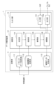
- FIG. 1 is a block diagram showing a configuration of a network system to which a data interpolation device according to an embodiment is connected.
- FIG. 2 is a block diagram showing the configuration of a data interpolation device according to an embodiment.
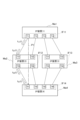
- FIG. 3 is an explanatory diagram showing the connection relationships of the interfaces mounted on a plurality of IP devices according to the first embodiment.
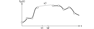
- FIG. 4A is a graph showing traffic data f23(t) of port T23 in which a loss occurs during time period x1.
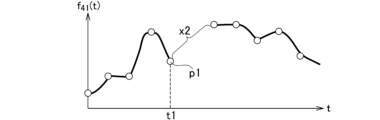
- FIG. 4B is a graph showing traffic data f41(t) of port T41 adjacent to port T23.
- FIG. 4C is a graph showing traffic data f11(t) of port T11 having a logical connection relationship with port T23.
- FIG. 4D is a graph showing traffic data f'23(t) after the gaps have been filled.
- FIG. 5 is a flowchart showing a processing procedure of the data interpolation device according to the first embodiment.
- FIG. 6 is an explanatory diagram showing the connection relationships of the interfaces mounted on a plurality of IP devices and a transmission device according to the second embodiment.
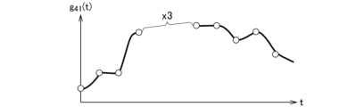
- FIG. 7A is a graph showing traffic data g41(t) of port Q41, in which a loss occurs during time period x3.
- FIG. 7B is a graph showing traffic data multiplexed in a transmission device having an aggregation function.
- FIG. 7C is a graph showing traffic data f31(t) of port T31 adjacent to port Q41.
- FIG. 7D is a graph showing traffic data g11(t) of port Q11 which has a logical connection relationship with port Q41.
- FIG. 8 is an explanatory diagram showing the data length of an IP packet and an Ethernet frame.
- FIG. 9 is a flowchart showing a processing procedure of the data interpolation device according to the second embodiment.
- FIG. 10 is an explanatory diagram showing the connection relationships of the interfaces mounted on a plurality of IP devices and a transmission device according to the third embodiment.
- FIG. 11A is a graph showing traffic data g41(t) of port Q41.
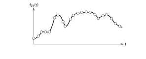
- FIG. 11B is a graph showing traffic data f21(t) of port T21.
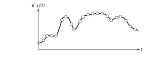
- FIG. 11C is a graph showing traffic data g'41(t) obtained by multiplying traffic data f21(t) by a coefficient and interpolating traffic data g41(t).
- FIG. 12 is a block diagram showing the hardware configuration of this embodiment.
- FIG. 1 is a block diagram showing the configuration of a network system to which a data interpolation device according to an embodiment is connected.
- the network system includes a data interpolation device 1, a management device 2, and a network 3.
- the network 3 includes multiple network devices M (referred to as "NW devices" in the figure).
- the network devices M are, for example, IP devices Ma provided in the IP layer and transmission devices Mb provided in the transmission layer (see Figures 3 and 6, described below).
- the network device M is an IP device Ma
- the IP device Ma is, for example, a router.
- the management device 2 acquires traffic data for each interface measured by each network device M.
- the management device 2 transmits the acquired traffic data to the data interpolation device 1.
- the data interpolation device 1 interpolates missing data when a loss occurs in the traffic data of an interface installed in each network device M.
- FIG. 2 is a block diagram showing a detailed configuration of the data interpolation device 1.
- the data interpolation device 1 includes a storage unit 11, a calculation unit 12, and an input/output unit 13.
- the memory unit 11 includes a traffic data memory unit 111, a connection relationship memory unit 112, and an interpolation data memory unit 113.
- the traffic data storage unit 111 stores traffic data of the interfaces installed in each network device M detected by the management device 2.
- connection relationship storage unit 112 stores information indicating the connection relationships of the interfaces installed in each network device M connected to the network 3.
- the connection relationships include physical connection relationships and logical connection relationships.
- FIG. 3 is an explanatory diagram showing the connection relationships of the interfaces IF11 to IF14 mounted on multiple IP devices Ma (Ma1 to Ma4).
- IP device Ma is an example of the network device M shown in FIG. 1.
- IP device Ma1 when one of the multiple IP devices is specifically referred to, it will be written with a suffix such as "IP device Ma1", and when it is not specified or referred to collectively, it will be written as "IP device Ma”.
- a suffix such as "interface IF11”
- Each IP device Ma shown in FIG. 3 has an interface IF.
- T11 to T44 shown in FIG. 3 indicate the ports of the interface IF mounted on each IP device Ma.
- interface IF11 of IP device Ma1 has connection ports T11 to T14.
- port T11 of interface IF11 and port T21 of interface IF12 are adjacent and have a physical connection relationship.
- packets are not generally generated or lost on the cable, so the traffic data of port T11 of interface IF11 has a correlation with the traffic data of port T21 of interface IF12.
- the traffic data of port T11 of interface IF11 is transmitted to port T41 of interface IF14 mounted on IP device Ma4 via IP device Ma2. Therefore, a logical path P1 exists between port T11 of interface IF11 and port T41 of interface IF14, and the two have a logical connection relationship.
- the traffic data of port T11 of interface IF11 has a correlation with the traffic data of port T41 of interface IF14.
- connection relationship storage unit 112 shown in FIG. 2 stores information indicating the physical connection relationships and logical connection relationships of each of the IP devices Ma described above. In other words, the connection relationship storage unit 112 stores the connection relationships of the interfaces IF mounted on multiple network devices M.
- the interpolation data storage unit 113 stores traffic data in which missing data has been interpolated by the interpolation unit 124 described below.
- the calculation unit 12 includes a determination unit 121, a search unit 122, a reference unit 123, and an interpolation unit 124.
- the determination unit 121 acquires the traffic data of each interface IF stored in the traffic data storage unit 111, and determines any defects that occur in the acquired traffic data.
- FIG. 4A is a graph showing traffic data f23(t) of port T23 of interface IF12 mounted on IP device Ma2 shown in FIG. 3. As shown in FIG. 4A, there is a loss in traffic data f23(t) during time period x1. The determination unit 121 determines whether or not there is such a loss in traffic data.
- the search unit 122 refers to the connection relationships between the IP devices Ma stored in the connection relationship storage unit 112, and searches for interfaces that have physical and logical connection relationships with the interface IF that is determined to have a loss in traffic data.
- the search unit 122 searches for an interface IF adjacent to port T23.
- port T41 of interface IF14 is searched for.
- the search unit 122 further searches for an interface IF that has a logical connection relationship with port T23. Specifically, T41, which is adjacent to port T23 shown in FIG. 3, is logically connected to port T11 via logical path P1, so port T11 of interface IF11 is searched for.
- the reference unit 123 refers to the traffic data of the interface IF searched by the search unit 122 and determines whether or not there is traffic data to be used to fill in the gap. For example, as shown in FIG. 4A, when a gap occurs in the traffic data f23(t) of the port T23, it determines whether or not there is traffic data to be used to fill in the gap.
- FIG. 4B is a graph showing traffic data f41(t) of port T41 adjacent to port T23
- FIG. 4C is a graph showing traffic data f11(t) of port T11, which has a logical connection relationship with port T23.
- the reference unit 123 references the traffic data f41(t) shown in FIG. 4B and recognizes that data p1 exists that interpolates the time period x1 shown in FIG. 4A.
- the reference unit 123 references the traffic data f11(t) shown in FIG. 4C and recognizes that data p2 exists that interpolates the time period x1 shown in FIG. 4A.
- the interpolation unit 124 uses each piece of data recognized by the reference unit 123 to interpolate the gaps that occur in the traffic data f23(t) of port T23 shown in FIG. 3. At this time, the data to be used for the interpolation is selected in order of the highest correlation with port T23.
- the interpolation unit 124 refers to the traffic data f41(t) (Fig. 4B) of port T41 adjacent to port T23, and uses the data p1 contained therein to interpolate the data of time zone x1 shown in Fig. 4A. Furthermore, the interpolation unit 124 refers to the traffic data f11(t) (Fig. 4C) of port T11, which has a logical connection relationship with port T23, and uses the data p2 contained therein to interpolate the data of time zone x1 shown in Fig. 4A.
- traffic data f'23(t) is generated in which the missing parts are interpolated using data p1 and p2.
- the interpolation unit 124 outputs the traffic data f'23(t) after the missing parts have been interpolated to the interpolated data storage unit 113 and the output unit 132, which will be described later.
- the input/output unit 13 includes an input unit 131 and an output unit 132.
- the input unit 131 is connected to, for example, an HMI (Human Machine Interface) and inputs operation signals from the user.
- HMI Human Machine Interface
- the output unit 132 outputs the traffic data interpolated by the interpolation unit 124 to an external file, etc.
- the traffic data storage unit 111 acquires and stores the traffic data of the interface IF in each IP device Ma acquired by the management device 2.
- connection relationship storage unit 112 acquires data indicating the connection relationships of each IP device Ma from the management device 2 and stores the data.
- the connection relationships include physical connection relationships and logical connection relationships.
- step S13 the determination unit 121 determines whether or not there is a loss in each traffic data stored in the traffic data storage unit 111. For example, it determines that there is a loss of data in the time period x1 as shown in FIG. 4A in the traffic data f23(t) of the port T23 of the interface IF12 mounted on the IP device Ma2 shown in FIG. 3.
- step S14 If it is determined in step S14 that there is a defect (S14; YES), the process proceeds to step S15; if not (S14; NO), the process ends.
- step S15 the search unit 122 searches for an interface IF that has a connection relationship with port T23 of interface IF12 (one interface).
- step S16 the search unit 122 determines whether or not there is another interface that has a connection relationship with port T23 of interface IF12. If there is (S16; YES), the process proceeds to step S17. If not (S16; NO), the process proceeds to step S21. In step S21, an output unit (not shown) notifies the user that a loss has occurred in the traffic data. Then, this process ends.
- port T23 of interface IF12 has a connection relationship with port T41 of interface IF14 (another interface).
- Port T23 also has a logical connection relationship with port T11 of interface IF11 (another interface). Therefore, the processing in step S16 results in a YES judgment.
- the reference unit 123 references the traffic data of the interface IF that has a connection relationship with port T23. Specifically, during time period x1 in which there is a loss in traffic data f23(t) shown in FIG. 4A, data p1 exists in traffic data f41(t) of port T41 shown in FIG. 4B. In addition, data is lost during time period x2.
- data p2 exists in the traffic data f11(t) of port T11 shown in FIG. 4C.
- the reference unit 123 references the traffic data f41(t) of port T41 and the traffic data f11(t) of port T11 to obtain data p1 and p2.
- step S18 the interpolation unit 124 uses the data acquired by the reference unit 123 to interpolate the missing parts occurring in the traffic data f23(t). Specifically, the missing parts are interpolated using data p1 of the traffic data f41(t) and data p2 of the traffic data f11(t). As a result, as shown in FIG. 4D, the traffic data f'23(t) in which the missing parts have been interpolated is obtained.
- the interpolation unit 124 uses data p1 of traffic data f41(t) of interface IF14, which is in descending order of correlation with interface IF12 (one interface) among the other interfaces (IF14, IF11) searched for by the search unit 122, and further uses data p2 of traffic data f11(t) of interface IF11, which has a relatively low correlation, to interpolate the loss occurring in the traffic data f23(t).
- step S19 the interpolation unit 124 stores the interpolated traffic data f'23(t) in the interpolated data storage unit 113.
- step S20 the interpolation unit 124 outputs the interpolated traffic data f'23(t) to an external file or the like. In this way, the loss that has occurred in the traffic data f23(t) can be interpolated.
- the data interpolation device 1 includes a connection relationship storage unit 112 that stores the connection relationships of interfaces IF mounted on multiple network devices M (IP devices Ma), a determination unit 121 that determines losses occurring in the traffic data of the interfaces IF, a search unit 122 that searches for other interfaces having a connection relationship with one interface when a loss occurs in the traffic data of one interface, and an interpolation unit 124 that interpolates losses occurring in the traffic data of one interface based on the traffic data of the other interfaces.
- IP devices Ma IP devices Ma
- the traffic data of another interface IF that has a physical connection relationship with the one interface IF is referenced. Furthermore, the traffic data of another interface IF that has a logical connection relationship with the one interface IF is referenced.
- the loss can be interpolated by preferentially referencing the traffic data of an interface IF that has a higher correlation, making it possible to interpolate the missing data with higher accuracy.
- the network 3 shown in FIG. 1 is a multi-layer network
- the network 3 is a multi-layer network including an IP layer having a plurality of IP devices Ma and a transmission layer having a plurality of transmission devices Mb
- the IP layer and the transmission layer are described as an example, but other layers may be used. That is, a network having all layers crossing each other with different packet lengths may be used.
- the transmission device Mb is, for example, an OXC (optical cross-connect) provided in the transmission layer.
- the configuration of the data interpolation device according to the second embodiment is the same as that shown in FIG. 2, but the functions of the search unit 122 and the reference unit 123 differ from those of the first embodiment.
- the connection relationship storage unit 112 stores the connection relationship between interfaces spanning two layers. The configurations of the search unit 122 and the reference unit 123 of the data interpolation device according to the second embodiment are described below.
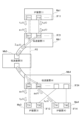
- FIG. 6 is an explanatory diagram showing the connection relationship between the interfaces IF11, IF13, and IF14 of multiple IP devices Ma (Ma1, Ma3, Ma4) provided in the IP layer, and the interfaces IF21 and IF24 of multiple transmission devices Mb (Mb1, Mb4, Mb5) provided in the transmission layer.
- the search unit 122 refers to the connection relationships stored in the connection relationship storage unit 112, and searches across layers for interfaces that have a physical connection relationship and a logical connection relationship with the interface IF that has been determined to have a loss in traffic data.
- Q11, Q12, ... and Q41, Q42, ... shown in Figure 6 indicate the port numbers of the interfaces IF mounted on the transmission devices Mb1 and Mb4. That is, the interface IF21 of the transmission device Mb1 has connection ports Q11, Q12, ..., and the interface IF24 of the transmission device Mb4 has connection ports Q41, Q42, .... For example, port T11 of interface IF11 and port Q11 of interface IF21 have a physical connection relationship.
- connection relationship storage unit 112 shown in FIG. 2 stores information indicating the physical connection relationship and logical connection relationship as described above.
- the transmission device Mb5 shown in FIG. 6 has an aggregation function that aggregates traffic transmitted from the transmission device Mb1. Specifically, the transmission device Mb5 aggregates traffic from each port Q11, Q12, ... of the transmission device Mb1 and transmits it to the transmission device Mb4.
- the connection section between the transmission devices Mb1 and Mb5 and the connection section between the transmission devices Mb5 and Mb4 are sections where traffic is aggregated and transmitted.
- at least one of the multiple network devices M arranged in the network 3 has an aggregation function that aggregates multiple traffic streams. Note that "aggregating traffic" includes not only aggregating traffic, but also multiplexing traffic.
- the search unit 122 searches for ports T31, T11, and Q11 that have a connection relationship with port Q41.
- the search unit 122 searches while excluding the traffic data of the above-mentioned transmission device Mb5 (a network device with an aggregation function).
- the traffic data of the transmission device Mb5 which is a network device with an aggregation function, is an aggregate of multiple traffic streams, and therefore cannot be used as data to fill in gaps.
- the search unit 122 excludes this traffic data from the traffic data to be searched.
- the search unit 122 searches for other interfaces that have a connection relationship with one interface from interfaces other than those of the network device M with an aggregation function.
- the interpolation unit 124 references the traffic data of the port with the higher correlation among ports T31, T11, and Q11 that have a connection relationship with port Q41, and interpolates the missing traffic data g41(t) of port Q41. Specifically, since port Q11 exists at the connection point between layers, the traffic data g11(t) of port Q11 is considered to be highly correlated with the traffic data g41(t) of port Q41.
- ports T31 and T11 are on a different layer from port Q41, a difference occurs in the traffic data. That is, when crossing layers, even if the interfaces have a connection relationship, a difference in packet length exists between the IP packet and the Ethernet frame as shown in FIG. 8. That is, since a header and an FCS (Frame Check Sequence) are added to the Ethernet frame transmitted by transmission device Mb4 for the IP packets transmitted by IP devices Ma1 and Ma3, the traffic data f31(t) and f11(t) are not equal to g41(t).
- FCS Frae Check Sequence
- the interpolation unit 124 interpolates missing data by preferentially referencing traffic data g11(t) of port Q11, which has a higher correlation with traffic data g41(t) of port Q41. Furthermore, if no interpolation data exists in traffic data g11(t), the interpolation unit 124 interpolates missing data by using traffic data f31(t) or f11(t), which has a relatively lower correlation.
- FIG. 7A is a graph showing traffic data g41(t) of port Q41 of interface IF24 mounted on transmission device Mb4 shown in FIG. 6. Traffic data g41(t) is missing during time period x3.
- FIG. 7B is a graph showing traffic data ⁇ g1i(t) passing through transmission device Mb5
- FIG. 7C is a graph showing traffic data f31(t) of port T31
- FIG. 7D is a graph showing traffic data g11(t) of port Q11.
- port Q41 is adjacent to port T31 of interface IF13 mounted on IP device Ma3, and they are physically connected.
- traffic data g41(t) of port Q41 and traffic data f31(t) of port T31 are in different layers, so it is believed that a difference occurs. Therefore, data p11 and p12 in time slot x3 of traffic data f31(t) shown in FIG. 7C are not used as data to fill in the gaps in traffic data g41(t).
- port Q41 has a logical connection with port Q11 of interface IF21 mounted on transmission device Mb1. It is considered that traffic data g41(t) of port Q41 and traffic data g11(t) of port Q11 are almost the same. Therefore, as shown in FIG. 7D, traffic data g41(t) is interpolated using data p21 and p22 of time zone x3 of traffic data g11(t).
- the interpolation unit 124 references the traffic data g11(t) of interface IF21 (another interface) that has a connection relationship with the one interface and exists at the connection point between two layers (IP layer, transmission layer) to interpolate the loss of the one interface.
- the transmission device Mb5 shown in FIG. 6 aggregates multiple traffic streams. Therefore, the traffic data ⁇ g1i(t) passing through the transmission device Mb5 is data in which multiple traffic streams are aggregated, as shown in FIG. 7B. Therefore, this traffic data is not used to fill in the gaps.
- the interpolation unit 124 references the traffic data of another interface that has a connection relationship with the one interface and exists at the connection point between the layers, and interpolates the loss in the one interface.
- Steps S31 to S35 shown in FIG. 9 are similar to steps S11 to S15 shown in FIG. 5.
- Steps S39 to S41 shown in FIG. 9 are similar to steps S18 to S20 shown in FIG. 5. Therefore, the processing of steps S36 to S38 will be explained below.
- step S34 of FIG. 9 when it is detected that a loss has occurred in the traffic data g41(t) of port Q41 of interface IF24 mounted on transmission device Mb4 shown in FIG. 6, in step S35 the search unit 122 searches for an interface IF that has a connection relationship with port Q41.
- interface IF13 of IP device Ma3, transmission device Mb5, interface IF21 of transmission device Mb1, and interface IF11 of IP device Ma1 are searched for.
- step S36 the search unit 122 excludes traffic data of the network device M that has an aggregation function.
- the transmission device Mb5 shown in FIG. 6 has an aggregation function that aggregates multiple traffic streams.
- the search unit 122 excludes the transmission device Mb5 from the searched interfaces.
- step S37 the search unit 122 determines whether or not there is another interface that has a connection relationship with port Q41 of interface IF24. If there is (S37; YES), the process proceeds to step S38; if not (S37; NO), the process proceeds to step S42. In step S42, an output unit (not shown) notifies the user that a loss has occurred in the traffic data. Then, this process ends.
- port Q41 of interface IF24 has a connection relationship with port Q11 of interface IF21 (another interface).
- Port Q41 also has a connection relationship with ports T31 and T11.
- step S38 the reference unit 123 references the traffic data g11(t) of port Q11. Specifically, during time period x3 in which a loss occurs in the traffic data g41(t) shown in FIG. 7A, data p21 and p22 exist in the traffic data g11(t) of port Q11 shown in FIG. 7D. Then, in step S39, the interpolation unit 124 uses the data p21 and p22 to interpolate the loss.
- steps S40 and S41 is similar to the processing in steps S19 and S20 shown in FIG. 5, so a description thereof will be omitted.
- the loss can be interpolated using traffic data of other interfaces that have a connection relationship with this one interface.
- the traffic data includes peculiar fluctuations such as bursts, as in the first embodiment described above, it is possible to interpolate the loss with high precision.
- the interpolation unit 124 references traffic data g11(t) of port Q11 mounted on interface IF21 that has a connection relationship with port Q41 and exists at the connection point between layers, and interpolates the loss of port Q41. This makes it possible to avoid referring to traffic data in different layers and prevent errors from occurring due to differences in data length.
- Fig. 10 is a block diagram showing the configuration of a network connected to a data interpolation device according to the third embodiment.
- the network shown in Fig. 10 is a multi-layer network consisting of an IP layer including IP devices Ma1 and Ma2, and a transmission layer including transmission devices Mb1 to Mb4.
- the data intervals of traffic data in the IP layer and traffic data in the transmission layer differ, the data intervals are unified by interpolating the data.
- traffic data g41(t) at port Q41 of interface IF24 mounted on transmission device Mb4 shown in FIG. 10 has a long data interval as shown in FIG. 11A
- traffic data f21(t) at port T21 of interface IF12 mounted on IP device Ma2 has a short data interval as shown in FIG. 11B.
- a difference occurs between the Ether Frame transmitted by the transmission device Mb4 and the IP packet transmitted by the IP device Ma2.
- an Ether Frame has a 26-byte header and a 4-byte FCS added per frame for the IP layer. If the payload of an IP packet is 1500 bytes, the difference can be corrected by multiplying the traffic data f21(t) by a predetermined coefficient "1.02".
- the interpolation unit 124 interpolates the loss of the one interface by using corrected data (data multiplied by a coefficient) of the traffic data of the other interface.
- traffic data g41(t) of port Q41 shown in FIG. 11A obtained by multiplying traffic data f21(t) of port T21 shown in FIG. 11B by "1.02"
- traffic data g'41(t) with a shorter data interval can be generated as shown in FIG. 11C.
- the data interpolation device makes it possible to standardize data intervals when network devices M (e.g., IP device Ma and transmission device Mb) with different data intervals are mixed.
- network devices M e.g., IP device Ma and transmission device Mb
- the traffic data f21(t) shown in FIG. 11B is multiplied by a fixed ratio of "1.02" to generate the traffic data g'41(t) shown in FIG. 11C, but the traffic data g'41(t) may also be generated by subtracting or adding a fixed numerical value.
- the data interpolation device 1 of the present embodiment described above can be, for example, a general-purpose computer system including a CPU (Central Processing Unit, processor) 901, memory 902, storage 903 (HDD: Hard Disk Drive, SSD: Solid State Drive), communication device 904, input device 905, and output device 906, as shown in FIG. 12.
- the memory 902 and storage 903 are storage devices.
- the CPU 901 executes a predetermined program loaded onto the memory 902, thereby realizing each function of the data interpolation device 1.
- the data interpolation device 1 may be implemented in one computer, or in multiple computers.
- the data interpolation device 1 may also be a virtual machine implemented in a computer.
- the program for the data interpolation device 1 can be stored on a computer-readable recording medium such as a HDD, SSD, USB (Universal Serial Bus) memory, CD (Compact Disc), or DVD (Digital Versatile Disc), or can be distributed via a network.
- a computer-readable recording medium such as a HDD, SSD, USB (Universal Serial Bus) memory, CD (Compact Disc), or DVD (Digital Versatile Disc), or can be distributed via a network.
- the computer-readable recording medium is, for example, a non-transitory recording medium.
Landscapes
- Engineering & Computer Science (AREA)
- Computer Networks & Wireless Communication (AREA)
- Signal Processing (AREA)
- Data Mining & Analysis (AREA)
- Environmental & Geological Engineering (AREA)
- Data Exchanges In Wide-Area Networks (AREA)
Abstract
Description
図1は、実施形態に係るデータ補間装置が接続されるネットワークシステムの構成を示すブロック図である。図1に示すように、ネットワークシステムは、データ補間装置1と、管理装置2と、ネットワーク3を備えている。
次に、第2実施形態について説明する。第2実施形態では、図1に示したネットワーク3がマルチレイヤである場合について説明する。第2実施形態ではネットワーク3が、複数のIP装置Maを備えるIPレイヤ、及び複数の伝送装置Mbを備える伝送レイヤを含むマルチレイヤである場合について説明する。なお、第2実施形態では、一例としてIPレイヤ及び伝送レイヤである場合について説明するが、他のレイヤであってもよい。即ち、パケット長が異なる全てのレイヤ跨ぎを有するネットワークであってもよい。伝送装置Mbは、例えば伝送レイヤに設けられるOXC(optical cross-connect)である。
次に、第3実施形態について説明する。図10は、第3実施形態に係るデータ補間装置に接続されるネットワークの構成を示すブロック図である。図10に示すネットワークは、IP装置Ma1、Ma2を含むIPレイヤ、及び、伝送装置Mb1~Mb4を含む伝送レイヤからなるマルチレイヤとされている。
2 管理装置
3 ネットワーク
11 記憶部
12 演算部
13 入出力部
111 トラヒックデータ記憶部
112 接続関係記憶部
113 補間データ記憶部
121 判定部
122 検索部
123 参照部
124 補間部
131 入力部
132 出力部
M ネットワーク装置
Ma(Ma1~Ma4) IP装置
Mb(Mb1~Mb5) 伝送装置
Claims (8)
- 複数のネットワーク装置に搭載されるインタフェースの接続関係を記憶する接続関係記憶部と、
前記インタフェースのトラヒックデータに生じる欠損を判定する判定部と、
一のインタフェースのトラヒックデータに欠損が生じたときに、前記一のインタフェースと接続関係を有する他のインタフェースを検索する検索部と、
前記他のインタフェースのトラヒックデータに基づいて、前記一のインタフェースのトラヒックデータに生じた欠損を補間する補間部と、
を備えたデータ補間装置。 - 前記接続関係は、各インタフェースの物理的な接続関係及び論理的な接続関係の少なくとも一方を含む
請求項1に記載のデータ補間装置。 - 前記検索部は、前記一のインタフェースとの相関性が高い順に、複数の他のインタフェースを検索し、
前記補間部は、前記検索部で検索された前記他のインタフェースのうち、前記一のインタフェースとの相関性が高い順となるインタフェースのトラヒックデータに基づいて前記欠損を補間する
請求項1または2に記載のデータ補間装置。 - 前記複数のネットワーク装置のうちの少なくとも一つは、複数のトラヒックを集約する集約機能を備えており、
前記検索部は、前記集約機能を有するネットワーク装置以外のインタフェースから、前記一のインタフェースと接続関係を有する他のインタフェースを検索する
請求項1または2に記載のデータ補間装置。 - 前記複数のネットワーク装置が配置されるネットワークは複数のレイヤを含み、
前記補間部は、
前記一のインタフェースのトラヒックデータに欠損が生じたときに、前記一のインタフェースと接続関係を有し、且つ、レイヤどうしの接続点に存在する前記他のインタフェースのトラヒックデータに基づいて、前記一のインタフェースの欠損を補間する
請求項1に記載のデータ補間装置。 - 前記複数のネットワーク装置が配置されるネットワークは複数のレイヤを含み、
前記補間部は、
前記一のインタフェースと前記他のインタフェースが異なるレイヤに存在する場合に、前記他のインタフェースのトラヒックデータを補正したデータを用いて前記一のインタフェースの欠損を補間する
請求項1に記載のデータ補間装置。 - ネットワーク装置に搭載されるインタフェースのトラヒックデータに生じる欠損を判定し、
一のインタフェースのトラヒックデータに欠損が生じたときに、前記インタフェースの接続関係が記憶されている接続関係記憶部を参照して前記一のインタフェースと接続関係を有する他のインタフェースを検索し、
前記他のインタフェースのトラヒックデータに基づいて、前記一のインタフェースのトラヒックデータに生じた欠損を補間する
データ補間方法。 - 請求項1または2に記載のデータ補間装置としてコンピュータを機能させるデータ補間プログラム。
Priority Applications (2)
| Application Number | Priority Date | Filing Date | Title |
|---|---|---|---|
| PCT/JP2023/005967 WO2024176296A1 (ja) | 2023-02-20 | 2023-02-20 | データ補間装置、データ補間方法、及びデータ補間プログラム |
| JP2025501927A JPWO2024176296A1 (ja) | 2023-02-20 | 2023-02-20 |
Applications Claiming Priority (1)
| Application Number | Priority Date | Filing Date | Title |
|---|---|---|---|
| PCT/JP2023/005967 WO2024176296A1 (ja) | 2023-02-20 | 2023-02-20 | データ補間装置、データ補間方法、及びデータ補間プログラム |
Publications (1)
| Publication Number | Publication Date |
|---|---|
| WO2024176296A1 true WO2024176296A1 (ja) | 2024-08-29 |
Family
ID=92500427
Family Applications (1)
| Application Number | Title | Priority Date | Filing Date |
|---|---|---|---|
| PCT/JP2023/005967 Ceased WO2024176296A1 (ja) | 2023-02-20 | 2023-02-20 | データ補間装置、データ補間方法、及びデータ補間プログラム |
Country Status (2)
| Country | Link |
|---|---|
| JP (1) | JPWO2024176296A1 (ja) |
| WO (1) | WO2024176296A1 (ja) |
Citations (1)
| Publication number | Priority date | Publication date | Assignee | Title |
|---|---|---|---|---|
| WO2022244198A1 (ja) * | 2021-05-20 | 2022-11-24 | 日本電信電話株式会社 | トポロジ推定装置、再取得判定方法およびトポロジ推定プログラム |
-
2023
- 2023-02-20 JP JP2025501927A patent/JPWO2024176296A1/ja active Pending
- 2023-02-20 WO PCT/JP2023/005967 patent/WO2024176296A1/ja not_active Ceased
Patent Citations (1)
| Publication number | Priority date | Publication date | Assignee | Title |
|---|---|---|---|---|
| WO2022244198A1 (ja) * | 2021-05-20 | 2022-11-24 | 日本電信電話株式会社 | トポロジ推定装置、再取得判定方法およびトポロジ推定プログラム |
Non-Patent Citations (1)
| Title |
|---|
| YUYA HATA, MIZUHITO NAKAMURA, YUSUKE MAKINO, ATSUSHI TAKADA, KYOKO YAMAGOSHI: "B-14-10 Proposal of a method for unifying time intervals in time series data analysis", PROCEEDINGS OF THE 2022 IEICE COMMUNICATIONS SOCIETY CONFERENCE; SEPTEMBER 6TH - 9TH, 2022, 23 August 2022 (2022-08-23), JP, pages 182, XP009557375 * |
Also Published As
| Publication number | Publication date |
|---|---|
| JPWO2024176296A1 (ja) | 2024-08-29 |
Similar Documents
| Publication | Publication Date | Title |
|---|---|---|
| KR102455332B1 (ko) | 네트워크 장치의 상태를 결정하는 방법 및 장치 | |
| US20200396135A1 (en) | Automatic prediction of behavior and topology of a network using limited information | |
| US12476875B2 (en) | Discovering a computer network topology for an executing application | |
| US9509627B2 (en) | Resource over-subscription | |
| US10756952B2 (en) | Determining a storage network path utilizing log data | |
| US11165654B2 (en) | Discovering and mapping the relationships between macro-clusters of a computer network topology for an executing application | |
| CN112702198B (zh) | 异常根因定位方法、装置、电子设备及存储介质 | |
| US20170366441A1 (en) | Transmitting test traffic on a communication link | |
| CN112436958B (zh) | 数据中心网络设备故障预测的方法、系统、设备及介质 | |
| US10210127B2 (en) | Storage system cabling analysis | |
| US10528568B2 (en) | Placement of services in stream computing applications | |
| US10805206B1 (en) | Method for rerouting traffic in software defined networking network and switch thereof | |
| CN114285746B (zh) | SRv6-TE业务的链路调优方法、装置、电子设备和可读介质 | |
| US11765042B2 (en) | Traffic application amount calculation apparatus, method and program | |
| CN114020631A (zh) | 用于链路测试的方法、装置及机器可读存储介质 | |
| US12500828B2 (en) | Optimizing path tracing to enable network assurance in existing network hardware | |
| US9253023B2 (en) | Network management system with a switchable flood revention mode pregarding fault events for a managed device | |
| CN116866274A (zh) | 数据传输路径的确定方法、装置、设备及可读存储介质 | |
| CN120263627A (zh) | 端口故障定位方法、装置、电子设备及存储介质 | |
| EP4677824A1 (en) | Optimizing path tracing to enable network assurance in existing network hardware | |
| US9559945B2 (en) | Message path selection within a network | |
| US20090037561A1 (en) | Automatically Adjusting Command Parameters To Support Devices Of A Computer Network | |
| CN121924052A (zh) | 网络层运行状态的监测方法、装置和计算机设备 | |
| CN106302598A (zh) | 传输路径优化方法及系统 | |
| CN119232796A (zh) | 消息中间件管理系统、设备、介质及产品 |
Legal Events
| Date | Code | Title | Description |
|---|---|---|---|
| 121 | Ep: the epo has been informed by wipo that ep was designated in this application |
Ref document number: 23923952 Country of ref document: EP Kind code of ref document: A1 |
|
| ENP | Entry into the national phase |
Ref document number: 2025501927 Country of ref document: JP Kind code of ref document: A |
|
| WWE | Wipo information: entry into national phase |
Ref document number: 2025501927 Country of ref document: JP |
|
| NENP | Non-entry into the national phase |
Ref country code: DE |
|
| 122 | Ep: pct application non-entry in european phase |
Ref document number: 23923952 Country of ref document: EP Kind code of ref document: A1 |