WO2024176290A1 - 診断システム、診断方法および記録媒体 - Google Patents
診断システム、診断方法および記録媒体 Download PDFInfo
- Publication number
- WO2024176290A1 WO2024176290A1 PCT/JP2023/005954 JP2023005954W WO2024176290A1 WO 2024176290 A1 WO2024176290 A1 WO 2024176290A1 JP 2023005954 W JP2023005954 W JP 2023005954W WO 2024176290 A1 WO2024176290 A1 WO 2024176290A1
- Authority
- WO
- WIPO (PCT)
- Prior art keywords
- tree
- equipment
- state
- image
- road
- Prior art date
- Legal status (The legal status is an assumption and is not a legal conclusion. Google has not performed a legal analysis and makes no representation as to the accuracy of the status listed.)
- Ceased
Links
Images




Classifications
-
- A—HUMAN NECESSITIES
- A01—AGRICULTURE; FORESTRY; ANIMAL HUSBANDRY; HUNTING; TRAPPING; FISHING
- A01G—HORTICULTURE; CULTIVATION OF VEGETABLES, FLOWERS, RICE, FRUIT, VINES, HOPS OR SEAWEED; FORESTRY; WATERING
- A01G7/00—Botany in general
-
- E—FIXED CONSTRUCTIONS
- E01—CONSTRUCTION OF ROADS, RAILWAYS, OR BRIDGES
- E01C—CONSTRUCTION OF, OR SURFACES FOR, ROADS, SPORTS GROUNDS, OR THE LIKE; MACHINES OR AUXILIARY TOOLS FOR CONSTRUCTION OR REPAIR
- E01C23/00—Auxiliary devices or arrangements for constructing, repairing, reconditioning, or taking-up road or like surfaces
- E01C23/01—Devices or auxiliary means for setting-out or checking the configuration of new surfacing, e.g. templates, screed or reference line supports; Applications of apparatus for measuring, indicating, or recording the surface configuration of existing surfacing, e.g. profilographs
Definitions
- the present invention relates to a diagnostic system, a diagnostic method, and a recording medium.
- equipment on roads that provides information to pedestrians In order for pedestrians to travel safely on roads, equipment on roads that provides information to pedestrians must be kept visible to pedestrians.
- An example of equipment on roads that provides information to pedestrians is signs. Signs may be obscured by trees, for example, and therefore may not be visible to pedestrians. For this reason, road managers, for example, monitor whether signs installed on roads under their management are visible. If the result of the monitoring shows that a sign is obscured by trees, the road manager, for example, prunes the trees, so that pedestrians can see the sign.
- road managers may use image recognition technology to determine whether a sign is visible based on images taken by a vehicle traveling on a road under their management.
- Patent Document 1 In the technology described in Patent Document 1, it can be difficult to determine whether or not it is necessary to remove the object covering the sign.
- the present disclosure aims to provide a diagnostic system etc. that can easily determine whether or not work is required to remove objects that are covering equipment that displays information to passersby.
- the diagnostic system disclosed herein includes an acquisition means for acquiring an image of a road, a detection means for detecting equipment on the road that provides information to passersby based on the image, an estimation means for estimating the coverage rate of equipment by objects that appear to overlap in the image, a condition identification means for identifying the condition of the objects that appear to overlap, a determination means for determining whether or not work is required to remove at least a portion of the object based on the coverage rate of equipment estimated by the estimation means and the condition of the object identified by the condition identification means, and an output means for outputting the result of the determination.
- the diagnostic method disclosed herein acquires an image of a road, detects equipment on the road that provides information to pedestrians based on the image, estimates the coverage rate of the equipment by objects that appear to overlap in the image, identifies the state of the objects that appear to overlap, and determines whether or not work is required to remove at least a portion of the object based on the estimated coverage rate of the equipment and the identified state of the object, and outputs the result of the determination.
- the recording medium of the present disclosure non-temporarily records a diagnostic program that causes a computer to execute the following processes: acquiring an image of a road; detecting equipment on the road that provides information to pedestrians based on the image; estimating the coverage rate of equipment by objects that appear to overlap in the image; identifying the state of the objects that appear to overlap; determining whether or not work is required to remove at least a portion of the object based on the estimated coverage rate of equipment and the state of the identified object; and outputting the result of the determination.
- This disclosure makes it easy to determine whether or not it is necessary to remove an object that is covering equipment that displays information to passersby.
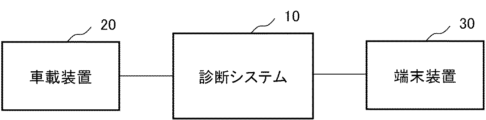
- FIG. 1 is a diagram illustrating an example of a configuration according to an embodiment of the present disclosure.
- FIG. 13 is a diagram showing an example of a state in which a sign is covered by tree leaves.
- FIG. 13 is a diagram showing an example of a situation in which a sign is covered by tree branches.
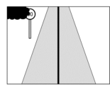
- FIG. 1 is a diagram illustrating an example of capturing an image of a road as a vehicle travels;
- FIG. 1 is a diagram illustrating an example of a configuration of a diagnostic system according to an embodiment of the present disclosure.
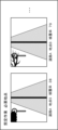
- FIG. 13 is a diagram illustrating an example of a display screen according to an embodiment of the present disclosure.
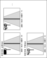
- FIG. 13 is a diagram illustrating an example of a display screen according to an embodiment of the present disclosure.
- FIG. 2 is a diagram illustrating an example of an operational flow of a diagnostic system according to an embodiment of the present disclosure.
- FIG. 2 is a diagram illustrating an example of a hardware configuration of a diagnostic system according to an embodiment of the present disclosure
- FIG. 1 is a diagram showing an example of the configuration of a road management system.
- the road management system includes a diagnostic system 10, an in-vehicle device 20, and a terminal device 30.
- the diagnostic system 10 is connected to the in-vehicle device 20 via a network, for example. Input and output of data between the diagnostic system 10 and the in-vehicle device 20 may be performed via a recording medium. For example, input and output of data between the diagnostic system 10 and the in-vehicle device 20 may be performed via a recording medium using a non-volatile semiconductor memory element.
- the diagnostic system 10 is also connected to the terminal device 30 via a network. There may be multiple in-vehicle devices 20 and multiple terminal devices 30. The number of in-vehicle devices 20 and terminal devices 30 is set as appropriate.
- a road management system is, for example, a system that manages whether equipment that provides information to pedestrians on a road is visible to pedestrians on the road.
- the diagnostic system 10 estimates the coverage rate of the equipment that provides information to pedestrians by objects, for example, based on an image taken of the road. Then, the diagnostic system 10 determines whether or not work is required to remove the objects that are covering the equipment that provides information to pedestrians, for example, based on the state of the objects and the coverage rate of the equipment by the objects.
- the equipment that provides information to pedestrians on a road may be, for example, a sign installed on the road.
- a sign is an object installed to provide pedestrians on a road with information necessary for traveling on the road.
- a sign provides, for example, information on guidance, warning, regulations, and instructions to pedestrians on a road.
- a sign provides, for example, information to pedestrians on a road using characters or symbols specified by law.
- the information provided by a sign is not limited to the above.
- the equipment that provides information to pedestrians on a road may include traffic lights and convex mirrors.
- the equipment that provides information to pedestrians on a road may be a display device that displays congestion information, lane restrictions, road closures, road surface conditions, and weather information.
- the equipment that provides information to pedestrians on a road may be a signboard that guides pedestrians to facilities or destinations.
- the equipment that provides information to pedestrians on a road is not limited to the above.
- the object that covers the equipment may be, for example, a tree.
- the object that covers the equipment may be a flag installed on the side of the road.
- the object that covers the equipment is not limited to the above.
- Equipment that provides information to pedestrians on a road is, for example, equipment installed on the shoulder of a road, above a driving lane, and in a center divider. Equipment that provides information to pedestrians on a road may also include equipment installed outside the road premises. Furthermore, a pedestrian on a road is, for example, a driver of a vehicle traveling on the road. A pedestrian on a road may also be, for example, a passenger other than the driver of a vehicle traveling on the road. A pedestrian on a road may also be a pedestrian. Furthermore, equipment that provides information to pedestrians on a road may be equipment identified by an imaging device or a sensor for a driving assistance system.
- a state in which an object covers an equipment means, for example, a state in which an object exists between a pedestrian on a road and the equipment, and the equipment is covered by the object as seen by the pedestrian.
- an object covers an equipment means, for example, a state in which an object exists between a pedestrian on a road and the equipment, and the pedestrian cannot see at least a part of the equipment.
- the state of an object also includes various states of the object. For example, if the object is a tree, the state of the object may be the state of the leaves of the tree. For example, if the object is a tree and the equipment is a sign, and there are leaves on the branches and the tree has leaves, the pedestrian cannot see the sign through the tree.
- a state in which a tree has no leaves includes, for example, a state in which a tree has only a few leaves on its branches.
- a state in which a tree has no leaves means a state in which the tree can be considered to have no leaves, compared to a state in which the tree has thick leaves. If the object is a tree, knowing whether the tree has leaves or not can determine whether passersby can see the sign through the tree.
- the coverage rate can be estimated to be the same as when there are leaves. For example, when the same tree covers a sign, even if the area of the sign is reflected between the branches in winter when there are no leaves, the coverage rate can be estimated to be the same as in summer when there are thick leaves. This is because the recognition model used for image recognition identifies the entire area inside the outer periphery of the area where the branches are present as the tree area, for example. However, when determining whether or not it is necessary to remove a tree covering a sign, if the tree branches have no leaves, the sign may be visible between the branches.
- the diagnostic system 10 determines whether or not it is necessary to remove an object covering equipment that presents information to passersby, for example, based on the state of the object and the coverage rate of the equipment by the object.
- Figure 2 is an example of an image showing a sign that is partially obscured by a leafy tree.
- a regulatory sign indicating a speed limit is installed on the left side of the road.
- the number indicated by the sign is not visible to pedestrians due to the leaves of the tree.
- the road administrator needs to prune the trees to remove the part obscuring the sign, making the number indicated by the sign visible to pedestrians.
- Figure 3 is an example of an image showing a sign that is partially obscured by the branches of a leafless tree.
- a regulatory sign indicating a speed limit is installed on the left side of the road.
- pedestrians can see the number indicated by the sign through the branches. For this reason, in the example screen state of Figure 3, the road administrator does not need to prune the tree immediately.
- the recognition model used for image recognition may determine that the area between the branches is also covered by trees in the example image of FIG. 3. If it is determined that the area between the branches is also covered by trees, the coverage rate of the sign by the trees in the example screen of FIG. 2 and the coverage rate of the sign by the trees in the example screen of FIG. 3 may be approximately the same. For this reason, if a threshold value is set for the coverage rate to determine whether or not the tree needs to be removed, if the threshold value is set low, it may be determined that the tree needs to be removed even though the sign can be seen between the branches as in FIG. 3 and the work of removing the tree by pruning is not necessary.
- the threshold value is set high, it may be determined that the tree needs to be removed even though the sign is covered by leaves growing on the tree branches as in FIG. 2 and cannot be seen, and the tree needs to be removed. For this reason, it is preferable to set the threshold value for determining whether or not the tree needs to be removed when there are leaves on the tree branches lower than the threshold value when there are no leaves and only branches.
- the threshold for determining whether or not tree removal is necessary is set as a criterion for determining whether or not tree removal is necessary, for example, using the coverage rate of signs by trees.
- the road management system determines that tree removal is necessary, for example, when the coverage rate of signs by trees is equal to or greater than the threshold. Also, in the road management system, the threshold for determining whether or not tree removal is necessary when the tree has no leaves is set higher than when the tree has leaves. In this way, the road management system can appropriately determine whether or not tree removal is necessary by determining whether or not tree removal is necessary based on a threshold according to the condition of the leaves on the tree, for example.
- the diagnostic system 10 identifies the state of the object covering the equipment, for example, based on an image of the road.
- the diagnostic system 10 also estimates the coverage rate of the equipment by the object based on the image of the road.
- the diagnostic system 10 determines whether or not work is required to remove the object covering the equipment, based on the estimated coverage rate and the state of the object.
- the vehicle-mounted device 20 is, for example, a device that uses a photographing device to capture images that the diagnostic system 10 uses to estimate the coverage rate of the equipment.
- the terminal device 30 is, for example, a terminal device used by a road administrator to operate the diagnostic system 10 and confirm whether or not the object needs to be removed.
- the road administrator is, for example, an entity that manages roads so that they can be traveled safely.
- the road administrator for example, monitors and maintains equipment related to the road.
- the road administrator for example, refers to the results of the judgment made by the diagnostic system 10 and determines whether or not work is required to remove the object covering the equipment.
- FIG. 4 is a diagram showing a schematic example of monitoring the state of road signs based on images captured by a camera mounted on a vehicle.
- a vehicle is traveling on a road.
- signs indicating speed limits are installed on the road.
- an in-vehicle device 20 is mounted on the vehicle.
- the in-vehicle device 20 uses a camera to capture an image of the road showing signs installed on the road.
- the in-vehicle device 20 outputs the captured image to, for example, the diagnostic system 10.
- a drive recorder is used as the in-vehicle device 20.
- the in-vehicle device 20 may be something other than a drive recorder.
- the diagnostic system 10 identifies the condition of the trees based on images acquired from the vehicle-mounted device 20.
- the diagnostic system 10 also estimates the coverage rate of the trees on the signs.
- the diagnostic system 10 determines whether or not the trees need to be removed based on the condition of the trees and the coverage rate of the trees on the signs.
- the diagnostic system 10 outputs the result of the determination on whether or not the trees need to be removed to, for example, the terminal device 30.
- the terminal device 30 outputs the result of the determination on whether or not the trees need to be removed to, for example, a display device.
- the road administrator for example, refers to the result of the determination on whether or not the trees need to be pruned and decides whether or not the trees need to be removed by pruning.
- FIG. 5 is a diagram showing an example of the configuration of the diagnostic system 10.
- the diagnostic system 10 basically includes an acquisition unit 11, a detection unit 12, a state identification unit 13, an estimation unit 14, a judgment unit 15, and an output unit 16.
- the diagnostic system 10 also includes, for example, a memory unit 17.
- the acquisition unit 11 acquires an image of a road.
- the acquisition unit 11 acquires an image of a road from, for example, the in-vehicle device 20.
- the image of a road is an image showing equipment on the road that provides information to pedestrians.
- the image of a road is captured by, for example, a camera mounted on a vehicle.
- the camera mounted on a vehicle captures an image of a road so that, for example, equipment on the road that provides information to pedestrians is captured in the image.
- the image of a road is, for example, a video captured by a drive recorder.
- the acquisition unit 11 may acquire the image of a road from the in-vehicle device 20 via a recording medium.
- the acquisition unit 11 may also acquire the image of a road from a server connected to a network.
- the acquisition unit 11 may also acquire information on the position of the vehicle from the in-vehicle device 20.
- the detection unit 12 detects equipment on a road that provides information to passersby based on an image of the road.
- the detection unit 12 detects equipment on the road that provides information to passersby, for example, on a road shown in an image of the road.
- the detection unit 12 detects equipment on the road that provides information to passersby, for example, using a recognition model.
- the recognition model is, for example, a learning model that identifies equipment that provides information to passersby on a road shown in an image.
- the recognition model may be a learning model that further identifies the state of an object covering the equipment.
- the recognition model is, for example, a machine learning model using a neural network.
- the recognition model is generated by learning the relationship between an image showing equipment that provides information to passersby on a road and the type of equipment.
- the recognition model may further learn the relationship between an image showing an object on or near the road and the state of the object.
- the learning data used to generate the recognition model is not limited to the above.
- the recognition model is, for example, generated in a system external to the diagnostic system 10.
- the detection unit 12 selects an image of a frame suitable for checking the state of coverage of the equipment by an object from among multiple frames showing the same equipment.
- An image suitable for checking the state of coverage of the equipment by an object is, for example, an image in which the size of the equipment shown in the image is within a standard range.
- the size of the equipment shown in the image is indicated, for example, by the number of pixels of the image.
- the size of the equipment shown in the image is set, for example, for each piece of equipment, based on the number of pixels of the image and the lens magnification of the shooting device.
- the detection unit 12 selects the image in which the size of the equipment is the largest from among the images in the standard range.
- an image suitable for checking the state of coverage of the equipment by an object may be an image in which the distance between the shooting point and the equipment is within a standard range.
- the distance between the shooting point and the equipment is calculated, for example, based on the speed of the vehicle and the time difference between the shooting time of each frame and the shooting time of the frame shot closest to the equipment.
- the frame shot closest to the equipment is, for example, a frame in which the equipment is not shown after the frame in question in the chronological order.
- the criteria for selecting an image of a frame suitable for checking the state of coverage of the equipment by an object are not limited to the above.
- the process of selecting an image of a frame suitable for checking the state of coverage of the equipment by an object may be performed by, for example, the determination unit 15.
- the detection unit 12 detects each piece of equipment by distinguishing them from one another, for example, based on at least one of the position of the equipment on the image, the shape of the equipment, and the design of the equipment. In addition, when equipment is captured in each frame of a time-series image, the detection unit 12 may detect that each piece of equipment is different equipment when the equipment is not captured in the image for a set number of consecutive frames or more and then the same type of equipment is captured in the image.
- the detection unit 12 detects that the equipment captured in the previous and following frames in which the equipment is not captured is the same equipment.
- the set value for the number of frames in which the equipment is not captured when the equipment captured in the previous and following frames is considered to be the same equipment is set, for example, based on the vehicle speed and the frame rate of the image capturing the road.
- the detection unit 12 may identify each piece of equipment based on the vehicle position information acquired by the acquisition unit 11.
- the position information of each sign is set, for example, by a road administrator.
- the detection unit 12 may identify each facility based on the vehicle position information acquired by the acquisition unit 11, the vehicle speed, and the vehicle acceleration.
- the state identification unit 13 identifies the state of an object that appears to overlap with the equipment detected by the detection unit 12 in an image of a road.
- the state identification unit 13, for example, identifies whether the state of the object is a state in which the equipment is visible through the object. For example, when the object is a tree and the equipment is a sign, the state of the object is the presence or absence of leaves on the tree. Furthermore, when the object is a tree, the state of the object may be the thickness of the tree's branches. When the object is a tree, the state of the object may be whether the tree is dead or not.
- the state identification unit 13, for example, identifies the state of the object covering the equipment based on the image identification result by the detection unit 12. Furthermore, the state identification unit 13 may identify the state of the object using a recognition model that is different from the recognition model used by the detection unit 12 in at least one of the learning data and the algorithm.
- the state identification unit 13 identifies the state of an object, for example, based on the color features of the overlapping portion of the object in the identification result of the recognition model. For example, the state of a tree is identified based on whether the chromaticity of the portion of the tree where the sign overlaps on the object image is that of the leaf or the branch. The range of chromaticity of the leaf and the branch are set, for example, based on the vegetation around the road. If the chromaticity identified from the image is within the range of the branch chromaticity, the state identification unit 13 identifies the tree as having no leaves on the branch. Furthermore, if the chromaticity of the portion of the tree where the sign overlaps on the image is within the range of the leaf chromaticity, the state identification unit 13 identifies the tree as having leaves on the branch.
- the state identification unit 13 may also identify the state of the leaves growing on the branches based on the color characteristics of the portion of the image where the identified tree overlaps with the sign.
- the state identification unit 13, for example, identifies the state of the leaves growing on the branches in multiple stages based on the chromaticity of the portion of the image where the tree identified with the tree overlaps with the sign.
- the multiple stages for identifying the state of the leaves are set, for example, by dividing the area between the chromaticity of the leaves and the color of the branch into multiple intervals based on the chromaticity in the XYZ color system.
- the state identification unit 13, for example, identifies which of the multiple stages the amount of leaves growing on the branches is in, depending on which of the multiple intervals the chromaticity of the portion of the image where the tree identified with the tree overlaps with the sign falls into.
- the state identification unit 13 may identify the thickness of the tree branches based on changes in at least one of the brightness and color in the image.
- the thickness of the branch is represented, for example, by the number of pixels in the image.
- the state identification unit 13 extracts the amount of change in at least one of the brightness and chromaticity in one direction in the image. Then, the state identification unit 13 identifies the thickness of the tree branches based on the period in which changes in at least one of the brightness and chromaticity occur in the area where the tree and the sign overlap.
- the state identification unit 13 may identify the state of the object by identifying whether the sky is visible through the object. For example, if the object is a tree and the tree is a sign, when the sky is visible through the object, the sign can be seen through the object.
- the state of the object may be whether the object exists temporarily or always exists. For example, the state of the object may be whether it is temporarily installed for work or permanently installed.
- the state of the object may also be a state in which the degree of covering the equipment changes due to the wind or the weight of the object. For example, if the object is a flag, the state may change between a state in which the flag covers the equipment behind it and the equipment cannot be seen, and a state in which the equipment is not covered and the equipment can be seen.
- the state of the object may also be whether it is in the same state throughout the year or in a state only in a specific season. For example, if the object is a tree that grows in the summer, the state identification unit 13 identifies it as a state in which it grows only during the summer. For example, if the object is snow, the state identification unit 13 identifies it as being present only during the winter period or for a few days.
- the estimation unit 14 estimates the coverage rate of the equipment by the object based on an image of the road.
- the coverage rate of the equipment is, for example, the ratio of the size of the part covered by the object to the size of the display surface of the equipment on the image.
- the size of the part covered by the object includes, for example, the part where the equipment is visible in the gap between the objects. For example, if the object is a tree and the equipment is a sign, the size of the part covered by the object includes the sign seen between the tree branches.
- the estimation unit 14 calculates the size of the equipment when it is not covered based on, for example, the dimensions of the display surface of the equipment.
- the size of the display surface of the equipment is represented by, for example, the number of pixels in the image.
- the estimation unit 14 calculates the size of the display surface of the equipment based on, for example, the shape of the display surface of the equipment detected by the detection unit 12. For example, if the equipment is circular and the detection unit 12 detects a part of the periphery of the circle, the estimation unit 14 considers the identified part to be a circle including the periphery and calculates the diameter of the circle. Then, the estimation unit 14 calculates the size of the circle based on the diameter of the circle. The estimation unit 14 calculates the coverage rate of the equipment by the object based on the calculated size of the display surface of the equipment and the size of the display surface of the equipment detected by the detection unit 12.
- the estimation unit 14 calculates the coverage rate of the equipment by the object, for example, by dividing the size of the display surface of the equipment detected by the detection unit 12 by the size of the display surface of the equipment when it is not covered by the object.
- the coverage rate may be expressed, for example, as two values, "high” or "low,” or may be expressed in multiple stages.
- the determination unit 15 determines whether or not an operation to remove at least a part of the object is necessary based on the coverage rate of the equipment estimated by the estimation unit 14 and the state of the object identified by the state identification unit 13. For example, when the coverage rate of the equipment estimated by the estimation unit 14 is equal to or greater than a threshold value according to the state of the object identified by the state identification unit 13, the determination unit 15 determines that an operation to remove at least a part of the object is necessary. For example, the state identification unit 13 sets a threshold value of the coverage rate of the equipment used to determine whether or not an operation is necessary based on the identification result of the state of the object.
- the state identification unit 13 determines that an operation to remove at least a part of the object is necessary when the coverage rate of the equipment estimated by the estimation unit 14 is equal to or greater than the set threshold.
- the operation to remove at least a part of the object is an operation to select a branch that covers the equipment.
- the operation to remove at least a part of the object may be an operation to remove the entire object.
- the operation to remove at least a part of the object may be cutting or transplanting the trunk of the tree.
- the determination unit 15 sets the threshold of the coverage rate of the equipment used to determine whether or not work is necessary higher when the state of the object is such that the equipment can be seen through the object than when the equipment cannot be seen through the object.
- the subject that sees the object is, for example, a person passing by on the road.
- the threshold for determining whether work to remove at least a part of the object is necessary is defined in a table showing the relationship between the state of the object and the threshold.
- the judgment unit 15 sets the threshold value of the sign coverage used to judge whether or not work is required to 40 percent when leaves are present and 60 percent when no leaves are present. In this case, the unit of coverage is percentage.
- the judgment unit 15 may set the threshold of the coverage rate of the equipment used to judge whether or not work is required in multiple stages according to the state of the object. For example, when the object is a tree, the judgment unit 15 may set the threshold in multiple stages according to the amount of leaves on the tree. For example, the judgment unit 15 may set different thresholds for a state in which there are no leaves on the tree branches, a state in which leaves grow on some of the tree branches, and a state in which the entire tree branches are covered with leaves. The judgment unit 15 may also set the threshold of the coverage rate of the equipment used to judge whether or not work is required using a function.
- the judgment unit 15 sets the threshold of the coverage rate of the equipment using a function in which the amount of leaves on the tree is an explanatory variable and the threshold is an objective variable.
- the amount of leaves on the tree is estimated, for example, by the state identification unit 13 based on the chromaticity of the tree shown in the image.
- the determination unit 15 may set a threshold for the coverage rate of equipment used to determine whether work is required depending on the importance of the equipment.
- the determination unit 15 sets the threshold for the coverage rate of equipment using, for example, a table showing the relationship between the type of equipment and the state of the object and the threshold. For example, when the equipment is a sign, the determination unit 15 sets different thresholds for guide signs and regulatory signs. For example, the determination unit 15 sets a lower threshold for regulatory signs such as "Stop" than for guide signs because not being able to see these signs can lead to accidents.
- the judgment unit 15 may set the threshold of the coverage rate of the equipment used to judge whether work is necessary higher when the sky is visible behind the object than when the sky is not visible. This is because when the sky is visible behind the object, it is highly likely that the facility covered by the object can be seen. Furthermore, the judgment unit 15 may set the threshold higher when the object is a temporary object than when it is a permanent object.
- the determination unit 15 may further determine the priority of the work of removing at least a part of the object.
- the determination unit 15 determines the priority of the work, for example, based on the ratio of the coverage rate of the equipment by the object to the threshold value of the coverage rate used to determine whether the work is necessary.
- the determination unit 15 calculates the priority of whether the work is necessary, for example, by normalizing the coverage rate of the equipment by the object based on the threshold value of the coverage rate used to determine whether the work is necessary.
- the determination unit 15 calculates the priority of whether the work is necessary, for example, by normalizing the value of the coverage rate of the equipment by the object by the threshold value of the coverage rate used to determine whether the work is necessary.
- the determination unit 15 determines that the priority of the work for equipment with a high calculated priority value is high.
- the priority of the work of removing at least a part of the object may be calculated by further multiplying the value of the coverage rate of the equipment by the object normalized using the threshold value for determining whether the work is necessary by a value indicating the importance of the equipment.
- the determination unit 15 may also determine whether or not an operation to remove at least a part of the object is necessary based on an index obtained by standardizing the coverage rate of the equipment by the object using a value set based on the state of the object.
- the determination unit 15 standardizes the value of the coverage rate of the equipment by the object by a value set based on the state of the object, for example.
- the value set based on the state of the object is set higher, for example, when the equipment is visible through the object than when the equipment is not visible through the object. For this reason, when the coverage rate values estimated by the estimation unit 14 are the same, the standardized index will be lower when the equipment is visible through the object than when the equipment is not visible through the object.
- the output unit 16 outputs the result of the judgment made by the judgment unit 15.
- the output unit 16 outputs, for example, the result of the judgment as to whether or not an operation to remove at least a part of the object is necessary.
- the output unit 16 outputs the result of the judgment made by the judgment unit 15 to, for example, the terminal device 30.
- the output unit 16 may output the result of the judgment made by the judgment unit 15 to a display device (not shown) that is connected to the diagnostic system 10.
- the output unit 16 outputs, for example, for each piece of equipment, the result of the judgment as to whether or not work is required to remove at least a portion of the object.
- the output unit 16 may output the identifier or position information of the equipment and the result of the judgment as to whether or not work is required to remove at least a portion of the object.
- the output unit 16 may also output the result of the judgment as to whether or not work is required to remove at least a portion of the object by superimposing it on a position corresponding to the installation point of the equipment on the map.
- the output unit 16 may output an image used in the judgment as to whether or not work is required to remove at least a portion of the object.
- the output unit 16 may output an image used in the judgment as to whether or not work is required to remove at least a portion of the object and the coverage rate of the equipment by the object. In addition to the result of the judgment, the output unit 16 may output the coverage rate of the equipment by the object. The output unit 16 may output, for example, whether or not work is required to remove at least a portion of the object, an image in which the equipment is shown, and the coverage rate of the equipment by the object. In addition, the judgment unit 15 may further output the state of the object for each piece of equipment. The determination unit 15 may further output the threshold value used to determine whether or not an operation to remove at least a portion of the object is necessary.
- the judgment unit 15 may further use at least one of the planting date and pruning history of trees around the equipment to judge whether or not work to remove at least a portion of the tree is necessary.
- the planting date of the tree is, for example, information indicating when the tree was planted.
- the planting date of the tree may also be the age of the tree.
- the pruning history is, for example, a record of past work to cut branches.
- the judgment unit 15 judges whether or not work to remove at least a portion of the tree is necessary for equipment around the equipment where the number of days since the planting of trees around the equipment or the last pruning is equal to or greater than a standard, using a lower threshold value than for equipment where the number of days since the last pruning is less than the standard.
- the judgment unit 15 may exclude the equipment from the judgment target for the judgment of whether or not work to remove at least a portion of the tree is necessary.
- the output unit 16 may output the result of the determination as to whether or not work is required to remove at least a portion of the object for the equipment installed at each of the multiple locations.
- the output unit 16 may output, in addition to the result of the determination as to whether or not work is required to remove at least a portion of the object for the equipment installed at each of the multiple locations.
- the output unit 16 may output, in addition to the result of the determination as to whether or not work is required to remove at least a portion of the object for the equipment installed at each of the multiple locations, the coverage rate of the equipment by the object.
- the output unit 16 may output, in addition to the result of the determination as to whether or not work is required to remove at least a portion of the object for the equipment installed at each of the multiple locations.
- the output unit 16 may further output the priority of the work. Also, the output unit 16 may output at least one of an image and a coverage rate of equipment that requires the work of removing at least a portion of the object in descending order of priority.
- FIG. 6 and 7 show examples of a display screen that displays the result of the judgment on whether or not work is required to remove the tree that is covering the sign.
- the example of the display screen in FIG. 6 is a display screen that displays the point where work is required to remove the tree that is covering the sign as the judgment result.
- an image of the point where the tree needs to be removed is displayed as "Point where pruning work is required”.
- an image of a sign installed at point S on road A and an image of a sign installed at point B are displayed.
- each of the signs shown in the image is covered by a tree.
- FIG. 6 each of the signs shown in the image is covered by a tree.
- the sign at point S is covered by the leaves of a tree. Also, in the example of the display screen in FIG. 6, the sign at point B is covered by the branches of a tree that has no leaves. In the example of the display screen in FIG. 6, the sign at point S and the sign at point B are in a state where passersby cannot see the numbers displayed on the sign. Also, in the example of the display screen in FIG. 6, the coverage rate of the sign at point S is displayed as 38. Also, in the example of the display screen in FIG. 6, the coverage rate of the sign at point B is displayed as 79.
- road managers can determine, for example, signs indicating that trees need pruning.
- the example of the display screen in Figure 7 is a display screen that displays, as a judgment result, points where work is required to remove the trees covering the sign and points where work is not required.
- an image of a point where tree removal is required is displayed as "Point where pruning work is required.”
- an image of a point where tree removal is required is displayed as "Point where pruning work is not required.”
- an image of a sign installed at point S on road A and an image of a sign installed at point B are displayed as images of points where tree removal work is required.
- an image of a sign at point C on road A is displayed as an image of a point where tree removal work is not required.
- each of the signs shown in the image is covered by trees.
- the sign at point S is covered by the leaves of a tree.
- the signs at points B and C are covered by the branches of a leafless tree.
- the signs at points S and B are in a state where passersby cannot see the numbers displayed on the signs.
- the sign at point C is in a state where passersby can see the numbers displayed on the sign through the branches.
- the coverage rate of the sign at point S is displayed as 38.
- the coverage rate of the sign at point B is displayed as 79.
- the coverage rate of the sign at point C is displayed as 55.
- the coverage rate of the sign at point C is higher than the coverage rate of the sign at point S.
- the threshold value for determining whether or not work is required is set higher than that for the sign at point S. For this reason, the sign at point C is determined to not require tree removal work.
- the diagnostic system 10 can appropriately determine whether or not tree removal work is required according to the state of the tree.
- the road administrator can, for example, determine which signs require tree pruning while confirming the validity of the judgment of the diagnostic system 10.
- the storage unit 17 stores, for example, data related to the process of determining whether or not an operation to remove at least a part of an object is necessary.
- the storage unit 17 stores, for example, an image of a road.
- the storage unit 17 stores, for example, a recognition model.
- the recognition model may be stored in a storage means other than the storage unit 17.
- the storage unit 17 may also store the result of the selection of an image to be used to check the state of coverage of a sign by an object.
- the storage unit 17 stores, for example, an image used to determine whether or not an operation to remove at least a part of an object is necessary.
- the storage unit 17 stores, for example, the coverage rate of a sign estimated by the estimation unit 14.
- the vehicle-mounted device 20 is equipped with, for example, a photographing device that photographs the road on which the vehicle is traveling.
- the photographing device of the vehicle-mounted device 20 for example, photographs images of the road including equipment that provides information to pedestrians.
- the photographing device for example, continuously photographs images of the road while the vehicle is traveling.
- the vehicle-mounted device 20 is equipped with, for example, a photographing device that photographs the front of the vehicle.
- the front of the vehicle is, for example, the direction in front of the driver of the vehicle when sitting in the driver's seat.
- the photographing device of the vehicle-mounted device 20 may photograph the rear of the vehicle.
- the rear of the vehicle is, for example, the direction behind the driver of the vehicle when sitting in the driver's seat.
- the vehicle-mounted device 20 outputs, for example, via a network, images of the road and data related to the vehicle's speed to the diagnostic system 10.
- the vehicle-mounted device 20 is equipped with, for example, a slot for mounting a removable recording medium.
- the in-vehicle device 20 may add information about the location where the image was taken to the captured image.
- the in-vehicle device 20 may use, for example, GNSS (Global Navigation Satellite System) to identify the location of the vehicle when the image was captured.
- GNSS Global Navigation Satellite System
- the in-vehicle device 20 may identify the location of the vehicle based on a beacon containing location information.
- the in-vehicle device 20 may identify the location where the image was taken based on the distance traveled from the point where the vehicle's location was identified and map information.
- the in-vehicle device 20 may also output the captured image to, for example, the diagnosis system 10.
- a drive recorder is used as the in-vehicle device 20.
- the in-vehicle device 20 is not limited to a drive recorder.
- the terminal device 30, obtains the result of the judgment as to whether or not work is required to remove at least a portion of the object.
- the terminal device 30 obtains the result of the judgment as to whether or not work is required to remove at least a portion of the object from the diagnostic system 10, for example.
- the terminal device 30 then outputs the result of the judgment as to whether or not work is required to remove at least a portion of the object to, for example, a display device not shown.
- the terminal device 30 obtains, for example, an image on which the judgment as to whether or not work is required to remove at least a portion of the object is made, and the coverage rate of the sign by the object in that image.
- the terminal device 30 then outputs the result of the judgment as to whether or not work is required to remove at least a portion of the object, the image used in the judgment, and the coverage rate of the equipment by the object to, for example, a display device not shown.
- the terminal device 30 may be, for example, a personal computer, a tablet computer, or a smartphone.
- the terminal device 30 is not limited to the above examples.
- Figure 8 shows an example of the operation flow when the diagnostic system 10 determines whether or not an object covering a sign needs to be removed.
- the acquisition unit 11 acquires an image of a road (step S11).
- the acquisition unit 11 acquires the image of a road from, for example, the in-vehicle device 20.
- the detection unit 12 detects equipment on the road that provides information to pedestrians based on the image of the road (step S12).
- the estimation unit 14 estimates the coverage rate of the equipment by the object that appears to overlap in the image (step S14).
- condition identification unit 13 identifies the condition of objects in the image that appear to overlap the detected equipment (step S15).
- the judgment unit 15 judges whether or not work to remove at least a portion of the object is necessary based on the state of the object identified by the state identification unit 13, the coverage rate of the equipment estimated by the estimation unit 14, and the state of the object identified by the state identification unit 13 (step S16).
- the output unit 16 When it is determined whether or not work is required to remove at least a portion of the object, the output unit 16 outputs the result of the determination as to whether or not work is required (step S17). The output unit 16 outputs the result of the determination as to whether or not work is required to, for example, the terminal device 30.
- step S13 if the equipment is not covered by the object (No in step S13), the output unit 16 outputs, as a result of the determination, information indicating that, for example, an operation to remove at least a part of the object is not necessary (step S17).
- the diagnostic system 10 identifies the state of an object that covers equipment that provides information to passersby on the road on an image of the road.
- the diagnostic system 10 also estimates the coverage rate of the equipment by the object. Then, based on the state of the object and the estimated coverage rate of the equipment, the diagnostic system 10 determines whether or not work is required to remove at least a portion of the object.
- the diagnostic system 10 identifies the state of the tree.
- the state of the tree is, for example, whether the tree has leaves on its branches.
- the diagnostic system 10 also estimates the coverage rate of the sign by the tree.
- the diagnostic system 10 determines whether or not it is necessary to remove at least a part of the tree based on a threshold value set according to the state of the tree and the coverage rate of the sign by the tree. For example, when the tree has no leaves, the threshold value is set lower than when the tree has thick leaves. This is because when the tree has no leaves, even if the coverage rate is estimated to be the same as when the tree has thick leaves, the sign may be visible through the branches.
- the diagnostic system 10 determines that it is necessary to remove at least a part of the tree.
- the road administrator refers to the determination result of the diagnostic system 10 and decides whether or not it is necessary to prune the tree. In this way, by using the diagnostic system 10, it is possible to easily determine whether or not it is necessary to remove an object that is covering the equipment that provides information to pedestrians.
- the manager of the road facility can, for example, refer to an image showing the facility covered by an object, and confirm the validity of the judgment result made by the diagnostic system 10 while deciding whether or not work is necessary.
- the manager of the road facility can easily determine the order of work by, for example, referring to the priority.
- the processes in the diagnostic system 10 may be distributed and executed in multiple information processing devices connected via a network.
- the processes in the detection unit 12, state identification unit 13, and estimation unit 14, and the processes in the judgment unit 15 may be executed in different information processing devices. It may be set as appropriate which of the multiple information processing devices executes each process in the diagnostic system 10.
- Each process in the diagnostic system 10 can be realized by executing a computer program on a computer.
- Figure 9 shows an example of the configuration of a computer 100 that executes a computer program that performs each process in the diagnostic system 10.
- the computer 100 comprises a CPU (Central Processing Unit) 101, memory 102, a storage device 103, an input/output I/F (Interface) 104, and a communication I/F 105.
- CPU Central Processing Unit
- the CPU 101 reads out and executes computer programs for performing each process from the storage device 103.
- the CPU 101 may be configured by a combination of multiple CPUs.
- the CPU 101 may also be configured by a combination of a CPU and another type of processor.
- the CPU 101 may be configured by a combination of a CPU and a GPU (Graphics Processing Unit).
- the memory 102 is configured by a DRAM (Dynamic Random Access Memory) or the like, and temporarily stores the computer programs executed by the CPU 101 and data being processed.
- the storage device 103 stores the computer programs executed by the CPU 101.
- the storage device 103 is configured by, for example, a non-volatile semiconductor storage element. Other storage devices such as a hard disk drive may be used for the storage device 103.
- the input/output I/F 104 is an interface that accepts input from an operator and outputs display data, etc.
- the communication I/F 105 is an interface that transmits and receives data between the in-vehicle device 20, the terminal device 30, and other information processing devices. Furthermore, the terminal device 30 may have a configuration similar to that of the computer 100.
- the computer programs used to execute each process can also be distributed by storing them on a computer-readable recording medium that non-temporarily records data.
- a computer-readable recording medium for example, a magnetic tape for recording data or a magnetic disk such as a hard disk can be used.
- an optical disk such as a CD-ROM (Compact Disc Read Only Memory) can also be used as the recording medium.
- a non-volatile semiconductor memory device can also be used as the recording medium.
- An acquisition means for acquiring an image of a road; A detection means for detecting a facility for presenting information to pedestrians on a road based on the image; an estimation means for estimating a coverage rate of the facility by objects that appear to overlap in the image; A state identifying means for identifying a state of the objects that appear to overlap; a determination means for determining whether or not an operation for removing at least a part of the object is necessary based on the coverage rate of the equipment estimated by the estimation means and the state of the object identified by the state identification means; and an output means for outputting a result of the judgment.
- the determination means determines that an operation to remove at least a part of the object is necessary when the coverage rate of the equipment is equal to or greater than a threshold value set according to a state of the object. 2.
- the object is a tree, and the state of the object is a state of leaves of the tree;
- the determination means determines that an operation to remove at least a part of the tree is necessary when a coverage rate of the facility by the tree is equal to or greater than a threshold value set according to a state of leaves of the tree. 3.
- the determination means determines whether or not an operation to remove at least a portion of the tree is necessary by further using at least one of the planting date and pruning history of the tree; A diagnostic system according to any one of claims 3 to 5.
- the object is a tree, and the state of the object is a thickness of a branch of the tree;
- the determination means determines that an operation to remove at least a part of the tree is necessary when a coverage rate of the facility by the tree is equal to or greater than a threshold value set according to a thickness of a branch of the tree. 3.
- the determining means further determines a priority of an operation of removing at least a portion of the object.
- a diagnostic system according to any one of claims 1 to 8.
- the determination means determines the priority of the work based on a ratio of a coverage rate of the equipment by the object to a threshold value of the coverage rate used for determining whether or not the work is necessary. 2.
- Appendix 12 A process of acquiring an image of a road; A process of detecting equipment for presenting information to pedestrians on a road based on the image; A process of estimating a coverage rate of the facility by objects that appear to overlap in the image; A process for identifying a state in which the objects appear to overlap; A process of determining whether or not an operation for removing at least a part of the object is necessary based on the estimated coverage rate of the facility and the identified state of the object; and a recording medium for non-temporarily recording a diagnostic program for causing a computer to execute the steps of:
Landscapes
- Life Sciences & Earth Sciences (AREA)
- Biodiversity & Conservation Biology (AREA)
- Botany (AREA)
- Ecology (AREA)
- Forests & Forestry (AREA)
- Environmental Sciences (AREA)
- Traffic Control Systems (AREA)
Abstract
Description
道路を撮影した画像を取得する取得手段と、
前記画像を基に、道路において通行者に情報を提示する設備を検出する検出手段と、
前記画像において見かけ上重なる物体による前記設備の被覆率を推定する推定手段と、
見かけ上重なる前記物体の状態を識別する状態識別手段と、
前記推定手段が推定した前記設備の被覆率と、前記状態識別手段が識別した前記物体の状態とを基に、前記物体の少なくとも一部を除去する作業の要否を判断する判断手段と、
前記判断の結果を出力する出力手段と
を備える診断システム。
前記判断手段は、前記設備の被覆率が、前記物体の状態に応じて設定される閾値以上である場合に、前記物体の少なくとも一部を除去する作業が必要であると判断する、
付記1に記載の診断システム。
前記物体は、樹木であり、かつ、前記物体の状態は、樹木の葉の状態であり、
前記判断手段は、前記樹木による前記設備の被覆率が、前記樹木の葉の状態に応じて設定される閾値以上の場合に、前記樹木の少なくとも一部を除去する作業が必要であると判断する、
付記2に記載の診断システム。
前記樹木の葉が無い状態の場合における閾値は、前記樹木の葉がある状態の場合における前記閾値よりも高く設定される、
付記3に記載の診断システム。
前記状態識別手段によって前記樹木の背景に空が識別された場合における閾値は、空が識別されていない場合における閾値よりも高く設定される、
付記3または4に記載の診断システム。
前記判断手段は、前記樹木の植栽時期、および剪定の履歴の少なくとも1つをさらに用いて、前記樹木の少なくとも一部を除去する作業の要否を判断する、
付記3から5いずれかに記載の診断システム。
前記物体は、樹木であり、かつ、前記物体の状態は、樹木の枝の太さであり、
前記判断手段は、前記樹木による前記設備の被覆率が、樹木の枝の太さに応じて設定される閾値以上の場合に、前記樹木の少なくとも一部を除去する作業が必要であると判断する、
付記2に記載の診断システム。
前記樹木の枝の太さが基準未満の場合における閾値は、前記樹木の枝の太さが基準以上の場合における閾値よりも高く設定される、
付記7に記載の診断システム。
前記判断手段は、前記物体の少なくとも一部を除去する作業の優先度をさらに判断する、
付記1から8いずれかに記載の診断システム。
前記判断手段は、作業の要否の判断に用いられる被覆率の閾値に対する、前記物体による前記設備の被覆率の割合に基づいて、前記作業の優先度を判断する、
付記1に記載の診断システム。
道路を撮影した画像を取得し、
前記画像を基に、道路において通行者に情報を提示する設備を検出し、
前記画像において見かけ上重なる物体による前記設備の被覆率を推定し、
見かけ上重なる前記物体の状態を識別し、
定した前記設備の被覆率と、識別した前記物体の状態とを基に、前記物体の少なくとも一部を除去する作業の要否を判断し、
前記判断の結果を出力する、
診断方法。
道路を撮影した画像を取得する処理と、
前記画像を基に、道路において通行者に情報を提示する設備を検出する処理と、
前記画像において見かけ上重なる物体による前記設備の被覆率を推定する処理と、
見かけ上重なる前記物体の状態を識別する処理と、
推定した前記設備の被覆率と、識別した前記物体の状態とを基に、前記物体の少なくとも一部を除去する作業の要否を判断する処理と、
前記判断の結果を出力する処置と
をコンピュータに実行させる診断プログラムを非一時的に記録する記録媒体。
11 取得部
12 検出部
13 状態識別部
14 推定部
15 判断部
16 出力部
17 記憶部
20 車載装置
30 端末装置
100 コンピュータ
101 CPU
102 メモリ
103 記憶装置
104 入出力I/F
105 通信I/F
Claims (12)
- 道路を撮影した画像を取得する取得手段と、
前記画像を基に、道路において通行者に情報を提示する設備を検出する検出手段と、
前記画像において見かけ上重なる物体による前記設備の被覆率を推定する推定手段と、
見かけ上重なる前記物体の状態を識別する状態識別手段と、
前記推定手段が推定した前記設備の被覆率と、前記状態識別手段が識別した前記物体の状態とを基に、前記物体の少なくとも一部を除去する作業の要否を判断する判断手段と、
前記判断の結果を出力する出力手段と
を備える診断システム。 - 前記判断手段は、前記設備の被覆率が、前記物体の状態に応じて設定される閾値以上である場合に、前記物体の少なくとも一部を除去する作業が必要であると判断する、
請求項1に記載の診断システム。 - 前記物体は、樹木であり、かつ、前記物体の状態は、樹木の葉の状態であり、
前記判断手段は、前記樹木による前記設備の被覆率が、前記樹木の葉の状態に応じて設定される閾値以上の場合に、前記樹木の少なくとも一部を除去する作業が必要であると判断する、
請求項2に記載の診断システム。 - 前記樹木の葉が無い状態の場合における閾値は、前記樹木の葉がある状態の場合における前記閾値よりも高く設定される、
請求項3に記載の診断システム。 - 前記状態識別手段によって前記樹木の背景に空が識別された場合における閾値は、空が識別されていない場合における閾値よりも高く設定される、
請求項3または4に記載の診断システム。 - 前記判断手段は、前記樹木の植栽時期、および剪定の履歴の少なくとも1つをさらに用いて、前記樹木の少なくとも一部を除去する作業の要否を判断する、
請求項3から5いずれかに記載の診断システム。 - 前記物体は、樹木であり、かつ、前記物体の状態は、樹木の枝の太さであり、
前記判断手段は、前記樹木による前記設備の被覆率が、樹木の枝の太さに応じて設定される閾値以上の場合に、前記樹木の少なくとも一部を除去する作業が必要であると判断する、
請求項2に記載の診断システム。 - 前記樹木の枝の太さが基準未満の場合における閾値は、前記樹木の枝の太さが基準以上の場合における閾値よりも高く設定される、
請求項7に記載の診断システム。 - 前記判断手段は、前記物体の少なくとも一部を除去する作業の優先度をさらに判断する、
請求項1から8いずれかに記載の診断システム。 - 前記判断手段は、作業の要否の判断に用いられる被覆率の閾値に対する、前記物体による前記設備の被覆率の割合に基づいて、前記作業の優先度を判断する、
請求項1に記載の診断システム。 - 道路を撮影した画像を取得し、
前記画像を基に、道路において通行者に情報を提示する設備を検出し、
前記画像において見かけ上重なる物体による前記設備の被覆率を推定し、
見かけ上重なる前記物体の状態を識別し、
推定した前記設備の被覆率と、識別した前記物体の状態とを基に、前記物体の少なくとも一部を除去する作業の要否を判断し、
前記判断の結果を出力する、
診断方法。 - 道路を撮影した画像を取得する処理と、
前記画像を基に、道路において通行者に情報を提示する設備を検出する処理と、
前記画像において見かけ上重なる物体による前記設備の被覆率を推定する処理と、
見かけ上重なる前記物体の状態を識別する処理と、
推定した前記設備の被覆率と、識別した前記物体の状態とを基に、前記物体の少なくとも一部を除去する作業の要否を判断する処理と、
前記判断の結果を出力する処置と
をコンピュータに実行させる診断プログラムを非一時的に記録する記録媒体。
Priority Applications (2)
| Application Number | Priority Date | Filing Date | Title |
|---|---|---|---|
| PCT/JP2023/005954 WO2024176290A1 (ja) | 2023-02-20 | 2023-02-20 | 診断システム、診断方法および記録媒体 |
| JP2025501921A JPWO2024176290A5 (ja) | 2023-02-20 | 診断システム、診断方法および診断プログラム |
Applications Claiming Priority (1)
| Application Number | Priority Date | Filing Date | Title |
|---|---|---|---|
| PCT/JP2023/005954 WO2024176290A1 (ja) | 2023-02-20 | 2023-02-20 | 診断システム、診断方法および記録媒体 |
Publications (1)
| Publication Number | Publication Date |
|---|---|
| WO2024176290A1 true WO2024176290A1 (ja) | 2024-08-29 |
Family
ID=92500623
Family Applications (1)
| Application Number | Title | Priority Date | Filing Date |
|---|---|---|---|
| PCT/JP2023/005954 Ceased WO2024176290A1 (ja) | 2023-02-20 | 2023-02-20 | 診断システム、診断方法および記録媒体 |
Country Status (1)
| Country | Link |
|---|---|
| WO (1) | WO2024176290A1 (ja) |
Citations (3)
| Publication number | Priority date | Publication date | Assignee | Title |
|---|---|---|---|---|
| JP2012187091A (ja) * | 2011-03-11 | 2012-10-04 | Nariyuki Mitachi | 街路樹の枝葉高さ自動測定センサシステム |
| JP2016151887A (ja) * | 2015-02-17 | 2016-08-22 | 株式会社東芝 | 路上監視装置、路上監視システム、方法及びプログラム |
| JP2018120409A (ja) * | 2017-01-25 | 2018-08-02 | 株式会社ユピテル | データ収集装置、道路状態評価支援装置、及びプログラム |
-
2023
- 2023-02-20 WO PCT/JP2023/005954 patent/WO2024176290A1/ja not_active Ceased
Patent Citations (3)
| Publication number | Priority date | Publication date | Assignee | Title |
|---|---|---|---|---|
| JP2012187091A (ja) * | 2011-03-11 | 2012-10-04 | Nariyuki Mitachi | 街路樹の枝葉高さ自動測定センサシステム |
| JP2016151887A (ja) * | 2015-02-17 | 2016-08-22 | 株式会社東芝 | 路上監視装置、路上監視システム、方法及びプログラム |
| JP2018120409A (ja) * | 2017-01-25 | 2018-08-02 | 株式会社ユピテル | データ収集装置、道路状態評価支援装置、及びプログラム |
Non-Patent Citations (3)
| Title |
|---|
| ANONYMOUS: "Issues in Maintenance and Management of Shade Trees through Heavy Pruning, Countermeasures Thereto", THESIS, no. 828, 10 March 2022 (2022-03-10), pages 57 - 63, XP093204306 * |
| HIROSE KIYOSHIGE: "The Modeling of a New Business Creation Process Based on the Case of the Development of a Road Sign Inspection Support System", FURUKAWA ELECTRIC TIMES, no. 51, 1 January 2020 (2020-01-01), pages 11 - 17, XP093204351 * |
| IIZUKA YASUO: "Inspection and diagnosis of street trees. Tree and Forest Health", JSTAGE, vol. 23, 1 January 2016 (2016-01-01), pages 55 - 60, XP093204310 * |
Also Published As
| Publication number | Publication date |
|---|---|
| JPWO2024176290A1 (ja) | 2024-08-29 |
Similar Documents
| Publication | Publication Date | Title |
|---|---|---|
| US12561585B2 (en) | Systems and methods for classifying driver behavior | |
| US12236692B2 (en) | Driver attention detection method | |
| US20220270376A1 (en) | Deterioration diagnosis device, deterioration diagnosis system, deterioration diagnosis method, and storage medium for storing program | |
| CA2132515C (en) | An object monitoring system | |
| JP6203208B2 (ja) | 道路構造物管理システム、及び道路構造物管理方法 | |
| CN111523368B (zh) | 信息处理装置、服务器以及交通管理系统 | |
| US20120021386A1 (en) | Method and apparatus for providing information about a vehicle | |
| US11479260B1 (en) | Systems and methods for proximate event capture | |
| CN111460938A (zh) | 一种车辆行驶行为实时监测方法及装置 | |
| KR102257078B1 (ko) | 좌표계를 이용한 안개 탐지 장치 및 그 방법 | |
| JP7293174B2 (ja) | 道路周辺物監視装置、道路周辺物監視プログラム | |
| JP2023536692A (ja) | レーストラックのaiベースのモニタリング | |
| CN114093160A (zh) | 危险驾驶检测装置、系统、方法及存储介质 | |
| JP7795427B2 (ja) | 車載装置およびデータ収集システム | |
| EP3244344A1 (en) | Ground object tracking system | |
| JP2024005056A5 (ja) | 車載装置およびデータ収集システム | |
| WO2024176290A1 (ja) | 診断システム、診断方法および記録媒体 | |
| CN114022862A (zh) | 一种交通标牌被遮挡的智能化检测方法及系统 | |
| JP7827174B2 (ja) | 標識診断システム、標識診断方法および標識診断プログラム | |
| WO2024166233A1 (ja) | 画像抽出システム、画像抽出方法および記録媒体 | |
| KR102145409B1 (ko) | 차량속도 측정이 가능한 시정거리 측정 시스템 | |
| KR102701572B1 (ko) | 안개 탐지 장치 | |
| WO2024201789A1 (ja) | 診断システム、診断方法及び記録媒体 | |
| FR3166466A1 (fr) | Procédé de détection d’un élément routier sur une chaussée. | |
| WO2024195134A1 (ja) | 支援システム、支援方法及び記録媒体 |
Legal Events
| Date | Code | Title | Description |
|---|---|---|---|
| 121 | Ep: the epo has been informed by wipo that ep was designated in this application |
Ref document number: 23923946 Country of ref document: EP Kind code of ref document: A1 |
|
| ENP | Entry into the national phase |
Ref document number: 2025501921 Country of ref document: JP Kind code of ref document: A |
|
| WWE | Wipo information: entry into national phase |
Ref document number: 2025501921 Country of ref document: JP |
|
| NENP | Non-entry into the national phase |
Ref country code: DE |
|
| 122 | Ep: pct application non-entry in european phase |
Ref document number: 23923946 Country of ref document: EP Kind code of ref document: A1 |