WO2024172117A1 - 車両制御装置、車両制御プログラム及び車両制御方法 - Google Patents
車両制御装置、車両制御プログラム及び車両制御方法 Download PDFInfo
- Publication number
- WO2024172117A1 WO2024172117A1 PCT/JP2024/005298 JP2024005298W WO2024172117A1 WO 2024172117 A1 WO2024172117 A1 WO 2024172117A1 JP 2024005298 W JP2024005298 W JP 2024005298W WO 2024172117 A1 WO2024172117 A1 WO 2024172117A1
- Authority
- WO
- WIPO (PCT)
- Prior art keywords
- vehicle
- intersection
- angle
- steering wheel
- setting unit
- Prior art date
- Legal status (The legal status is an assumption and is not a legal conclusion. Google has not performed a legal analysis and makes no representation as to the accuracy of the status listed.)
- Ceased
Links
Images


Classifications
-
- B—PERFORMING OPERATIONS; TRANSPORTING
- B60—VEHICLES IN GENERAL
- B60W—CONJOINT CONTROL OF VEHICLE SUB-UNITS OF DIFFERENT TYPE OR DIFFERENT FUNCTION; CONTROL SYSTEMS SPECIALLY ADAPTED FOR HYBRID VEHICLES; ROAD VEHICLE DRIVE CONTROL SYSTEMS FOR PURPOSES NOT RELATED TO THE CONTROL OF A PARTICULAR SUB-UNIT
- B60W30/00—Purposes of road vehicle drive control systems not related to the control of a particular sub-unit, e.g. of systems using conjoint control of vehicle sub-units
- B60W30/18—Propelling the vehicle
- B60W30/18009—Propelling the vehicle related to particular drive situations
- B60W30/18154—Approaching an intersection
-
- B—PERFORMING OPERATIONS; TRANSPORTING
- B60—VEHICLES IN GENERAL
- B60W—CONJOINT CONTROL OF VEHICLE SUB-UNITS OF DIFFERENT TYPE OR DIFFERENT FUNCTION; CONTROL SYSTEMS SPECIALLY ADAPTED FOR HYBRID VEHICLES; ROAD VEHICLE DRIVE CONTROL SYSTEMS FOR PURPOSES NOT RELATED TO THE CONTROL OF A PARTICULAR SUB-UNIT
- B60W10/00—Conjoint control of vehicle sub-units of different type or different function
- B60W10/20—Conjoint control of vehicle sub-units of different type or different function including control of steering systems
-
- B—PERFORMING OPERATIONS; TRANSPORTING
- B60—VEHICLES IN GENERAL
- B60W—CONJOINT CONTROL OF VEHICLE SUB-UNITS OF DIFFERENT TYPE OR DIFFERENT FUNCTION; CONTROL SYSTEMS SPECIALLY ADAPTED FOR HYBRID VEHICLES; ROAD VEHICLE DRIVE CONTROL SYSTEMS FOR PURPOSES NOT RELATED TO THE CONTROL OF A PARTICULAR SUB-UNIT
- B60W30/00—Purposes of road vehicle drive control systems not related to the control of a particular sub-unit, e.g. of systems using conjoint control of vehicle sub-units
- B60W30/02—Control of vehicle driving stability
- B60W30/045—Improving turning performance
-
- B—PERFORMING OPERATIONS; TRANSPORTING
- B60—VEHICLES IN GENERAL
- B60W—CONJOINT CONTROL OF VEHICLE SUB-UNITS OF DIFFERENT TYPE OR DIFFERENT FUNCTION; CONTROL SYSTEMS SPECIALLY ADAPTED FOR HYBRID VEHICLES; ROAD VEHICLE DRIVE CONTROL SYSTEMS FOR PURPOSES NOT RELATED TO THE CONTROL OF A PARTICULAR SUB-UNIT
- B60W30/00—Purposes of road vehicle drive control systems not related to the control of a particular sub-unit, e.g. of systems using conjoint control of vehicle sub-units
- B60W30/10—Path keeping
-
- B—PERFORMING OPERATIONS; TRANSPORTING
- B60—VEHICLES IN GENERAL
- B60W—CONJOINT CONTROL OF VEHICLE SUB-UNITS OF DIFFERENT TYPE OR DIFFERENT FUNCTION; CONTROL SYSTEMS SPECIALLY ADAPTED FOR HYBRID VEHICLES; ROAD VEHICLE DRIVE CONTROL SYSTEMS FOR PURPOSES NOT RELATED TO THE CONTROL OF A PARTICULAR SUB-UNIT
- B60W30/00—Purposes of road vehicle drive control systems not related to the control of a particular sub-unit, e.g. of systems using conjoint control of vehicle sub-units
- B60W30/18—Propelling the vehicle
- B60W30/18009—Propelling the vehicle related to particular drive situations
- B60W30/18159—Traversing an intersection
-
- B—PERFORMING OPERATIONS; TRANSPORTING
- B60—VEHICLES IN GENERAL
- B60W—CONJOINT CONTROL OF VEHICLE SUB-UNITS OF DIFFERENT TYPE OR DIFFERENT FUNCTION; CONTROL SYSTEMS SPECIALLY ADAPTED FOR HYBRID VEHICLES; ROAD VEHICLE DRIVE CONTROL SYSTEMS FOR PURPOSES NOT RELATED TO THE CONTROL OF A PARTICULAR SUB-UNIT
- B60W30/00—Purposes of road vehicle drive control systems not related to the control of a particular sub-unit, e.g. of systems using conjoint control of vehicle sub-units
- B60W30/18—Propelling the vehicle
- B60W30/182—Selecting between different operative modes, e.g. comfort and performance modes
-
- B—PERFORMING OPERATIONS; TRANSPORTING
- B60—VEHICLES IN GENERAL
- B60W—CONJOINT CONTROL OF VEHICLE SUB-UNITS OF DIFFERENT TYPE OR DIFFERENT FUNCTION; CONTROL SYSTEMS SPECIALLY ADAPTED FOR HYBRID VEHICLES; ROAD VEHICLE DRIVE CONTROL SYSTEMS FOR PURPOSES NOT RELATED TO THE CONTROL OF A PARTICULAR SUB-UNIT
- B60W40/00—Estimation or calculation of non-directly measurable driving parameters for road vehicle drive control systems not related to the control of a particular sub unit, e.g. by using mathematical models
- B60W40/02—Estimation or calculation of non-directly measurable driving parameters for road vehicle drive control systems not related to the control of a particular sub unit, e.g. by using mathematical models related to ambient conditions
-
- B—PERFORMING OPERATIONS; TRANSPORTING
- B60—VEHICLES IN GENERAL
- B60W—CONJOINT CONTROL OF VEHICLE SUB-UNITS OF DIFFERENT TYPE OR DIFFERENT FUNCTION; CONTROL SYSTEMS SPECIALLY ADAPTED FOR HYBRID VEHICLES; ROAD VEHICLE DRIVE CONTROL SYSTEMS FOR PURPOSES NOT RELATED TO THE CONTROL OF A PARTICULAR SUB-UNIT
- B60W60/00—Drive control systems specially adapted for autonomous road vehicles
- B60W60/001—Planning or execution of driving tasks
-
- B—PERFORMING OPERATIONS; TRANSPORTING
- B60—VEHICLES IN GENERAL
- B60W—CONJOINT CONTROL OF VEHICLE SUB-UNITS OF DIFFERENT TYPE OR DIFFERENT FUNCTION; CONTROL SYSTEMS SPECIALLY ADAPTED FOR HYBRID VEHICLES; ROAD VEHICLE DRIVE CONTROL SYSTEMS FOR PURPOSES NOT RELATED TO THE CONTROL OF A PARTICULAR SUB-UNIT
- B60W60/00—Drive control systems specially adapted for autonomous road vehicles
- B60W60/005—Handover processes
- B60W60/0053—Handover processes from vehicle to occupant
-
- B—PERFORMING OPERATIONS; TRANSPORTING
- B60—VEHICLES IN GENERAL
- B60W—CONJOINT CONTROL OF VEHICLE SUB-UNITS OF DIFFERENT TYPE OR DIFFERENT FUNCTION; CONTROL SYSTEMS SPECIALLY ADAPTED FOR HYBRID VEHICLES; ROAD VEHICLE DRIVE CONTROL SYSTEMS FOR PURPOSES NOT RELATED TO THE CONTROL OF A PARTICULAR SUB-UNIT
- B60W2510/00—Input parameters relating to a particular sub-units
- B60W2510/20—Steering systems
-
- B—PERFORMING OPERATIONS; TRANSPORTING
- B60—VEHICLES IN GENERAL
- B60W—CONJOINT CONTROL OF VEHICLE SUB-UNITS OF DIFFERENT TYPE OR DIFFERENT FUNCTION; CONTROL SYSTEMS SPECIALLY ADAPTED FOR HYBRID VEHICLES; ROAD VEHICLE DRIVE CONTROL SYSTEMS FOR PURPOSES NOT RELATED TO THE CONTROL OF A PARTICULAR SUB-UNIT
- B60W2552/00—Input parameters relating to infrastructure
- B60W2552/10—Number of lanes
-
- B—PERFORMING OPERATIONS; TRANSPORTING
- B60—VEHICLES IN GENERAL
- B60W—CONJOINT CONTROL OF VEHICLE SUB-UNITS OF DIFFERENT TYPE OR DIFFERENT FUNCTION; CONTROL SYSTEMS SPECIALLY ADAPTED FOR HYBRID VEHICLES; ROAD VEHICLE DRIVE CONTROL SYSTEMS FOR PURPOSES NOT RELATED TO THE CONTROL OF A PARTICULAR SUB-UNIT
- B60W2552/00—Input parameters relating to infrastructure
- B60W2552/15—Road slope, i.e. the inclination of a road segment in the longitudinal direction
-
- B—PERFORMING OPERATIONS; TRANSPORTING
- B60—VEHICLES IN GENERAL
- B60W—CONJOINT CONTROL OF VEHICLE SUB-UNITS OF DIFFERENT TYPE OR DIFFERENT FUNCTION; CONTROL SYSTEMS SPECIALLY ADAPTED FOR HYBRID VEHICLES; ROAD VEHICLE DRIVE CONTROL SYSTEMS FOR PURPOSES NOT RELATED TO THE CONTROL OF A PARTICULAR SUB-UNIT
- B60W2552/00—Input parameters relating to infrastructure
- B60W2552/30—Road curve radius
-
- B—PERFORMING OPERATIONS; TRANSPORTING
- B60—VEHICLES IN GENERAL
- B60W—CONJOINT CONTROL OF VEHICLE SUB-UNITS OF DIFFERENT TYPE OR DIFFERENT FUNCTION; CONTROL SYSTEMS SPECIALLY ADAPTED FOR HYBRID VEHICLES; ROAD VEHICLE DRIVE CONTROL SYSTEMS FOR PURPOSES NOT RELATED TO THE CONTROL OF A PARTICULAR SUB-UNIT
- B60W2552/00—Input parameters relating to infrastructure
- B60W2552/53—Road markings, e.g. lane marker or crosswalk
-
- B—PERFORMING OPERATIONS; TRANSPORTING
- B60—VEHICLES IN GENERAL
- B60W—CONJOINT CONTROL OF VEHICLE SUB-UNITS OF DIFFERENT TYPE OR DIFFERENT FUNCTION; CONTROL SYSTEMS SPECIALLY ADAPTED FOR HYBRID VEHICLES; ROAD VEHICLE DRIVE CONTROL SYSTEMS FOR PURPOSES NOT RELATED TO THE CONTROL OF A PARTICULAR SUB-UNIT
- B60W2554/00—Input parameters relating to objects
- B60W2554/40—Dynamic objects, e.g. animals, windblown objects
- B60W2554/402—Type
- B60W2554/4029—Pedestrians
-
- B—PERFORMING OPERATIONS; TRANSPORTING
- B60—VEHICLES IN GENERAL
- B60W—CONJOINT CONTROL OF VEHICLE SUB-UNITS OF DIFFERENT TYPE OR DIFFERENT FUNCTION; CONTROL SYSTEMS SPECIALLY ADAPTED FOR HYBRID VEHICLES; ROAD VEHICLE DRIVE CONTROL SYSTEMS FOR PURPOSES NOT RELATED TO THE CONTROL OF A PARTICULAR SUB-UNIT
- B60W2554/00—Input parameters relating to objects
- B60W2554/40—Dynamic objects, e.g. animals, windblown objects
- B60W2554/404—Characteristics
- B60W2554/4045—Intention, e.g. lane change or imminent movement
-
- B—PERFORMING OPERATIONS; TRANSPORTING
- B60—VEHICLES IN GENERAL
- B60W—CONJOINT CONTROL OF VEHICLE SUB-UNITS OF DIFFERENT TYPE OR DIFFERENT FUNCTION; CONTROL SYSTEMS SPECIALLY ADAPTED FOR HYBRID VEHICLES; ROAD VEHICLE DRIVE CONTROL SYSTEMS FOR PURPOSES NOT RELATED TO THE CONTROL OF A PARTICULAR SUB-UNIT
- B60W2710/00—Output or target parameters relating to a particular sub-units
- B60W2710/20—Steering systems
- B60W2710/207—Steering angle of wheels
Definitions
- This specification discloses technology for autonomously controlling vehicle operation.
- Patent Document 1 a technology for autonomously controlling vehicle driving recognizes environmental information around intersections. Then, when the vehicle attempts to turn right or left at an intersection, if traction control is activated and the vehicle waits to turn, the vehicle determines that it is in a safe position and waits to turn in that safe waiting area.
- One of the purposes of the disclosure of this specification is to provide a vehicle control device, a vehicle control program, and a vehicle control method that improve driving convenience.
- One aspect disclosed herein is a vehicle control device that autonomously controls driving of a vehicle, an environment recognition unit that recognizes environmental information at an intersection;
- the vehicle includes a setting unit that uses environmental information to set the angle of the steering wheels of the vehicle when the vehicle makes a temporary stop to turn right or left at an intersection.
- a vehicle control program for autonomously controlling driving of a vehicle, comprising: At least one processing unit, Recognizing environmental information at an intersection; The system is configured to use the environmental information to set the angle of the steering wheels of the host vehicle when the host vehicle makes a temporary stop in conjunction with turning right or left at an intersection.
- Another aspect disclosed herein is a vehicle control method for autonomously controlling driving of a vehicle, the method being executed by at least one processing unit, the method comprising: Recognizing environmental information at an intersection; Using the environmental information, the method includes setting the angle of the steering wheels of the host vehicle when the host vehicle makes a temporary stop in order to turn right or left at an intersection.
- the angle of the steering wheels can be optimized in accordance with the environment of the intersection, taking into account the start of the vehicle after the temporary stop. Therefore, after restarting, the vehicle can smoothly complete the right or left turn. This improves convenience when driving.
- FIG. 1 is a configuration diagram showing an overall picture of a vehicle system.
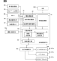
- FIG. 2 is a block diagram showing details of an autonomous driving ECU.
- FIG. FIG. FIG. FIG. FIG. FIG. FIG. FIG. FIG. FIG. 4 is a flowchart showing a processing method performed by the autonomous driving ECU.
- FIG. 2 is a diagram illustrating a crosswalk and a continuous intersection.
- 4 is a flowchart showing a processing method performed by the autonomous driving ECU.
- 4 is a flowchart showing a processing method performed by the autonomous driving ECU.
- FIG. 2 is a diagram showing an example of multiple lanes for right and left turns. 4 is a flowchart showing a processing method performed by the autonomous driving ECU.
- FIG. 1 is a configuration diagram showing an overall picture of a vehicle system.
- FIG. 2 is a block diagram showing details of an autonomous driving ECU.
- FIG. FIG. FIG. FIG. FIG. FIG. FIG. FIG. FIG. FIG. FIG. FIG. FIG. 4
- FIG. 13 is a diagram showing an example in which an oncoming vehicle is present; 4 is a flowchart showing a processing method performed by the autonomous driving ECU.
- FIG. 13 is a diagram showing an example of orbital interference.
- 4 is a flowchart showing a processing method performed by the autonomous driving ECU.
- 4 is a flowchart showing a processing method performed by the autonomous driving ECU.
- 4 is a flowchart showing a processing method performed by the autonomous driving ECU.
- FIG. 13 is a diagram showing an example in which the angle ⁇ is large.
- 4 is a flowchart showing a processing method performed by the autonomous driving ECU.
- 4 is a flowchart showing a processing method performed by the autonomous driving ECU.
- 4 is a flowchart showing a processing method performed by the autonomous driving ECU.
- FIG. 4 is a flowchart showing a processing method performed by the autonomous driving ECU.
- 4 is a flowchart showing a processing method performed by the autonomous driving ECU.
- 4 is a flowchart showing a processing method performed by the autonomous driving ECU.
- FIG. 13 is a diagram showing an example in which an oncoming vehicle is present;
- 4 is a flowchart showing a processing method performed by the autonomous driving ECU.
- 4 is a flowchart showing a processing method performed by the autonomous driving ECU.
- 4 is a flowchart showing a processing method performed by the autonomous driving ECU.
- FIG. 2 is a block diagram showing details of an autonomous driving ECU.
- 4 is a flowchart showing a processing method performed by the autonomous driving ECU.
- the vehicle system 1 is capable of executing autonomous control of driving (hereinafter, autonomous driving control) and can be used, for example, in vehicles with automation levels 2 to 5.
- the vehicle system 1 is mounted on a host vehicle Am as a vehicle.
- the automation level is an index indicating the stage of autonomous driving of an autonomous vehicle, and there can be multiple levels as defined by, for example, the SAE.
- the automation levels are, for example, classified into levels 0 to 5 as follows:
- Level 0 is a level where the driver performs all driving tasks without system intervention.
- the driving task may be another term for dynamic driving task.
- Driving tasks include, for example, steering, acceleration/deceleration, and periphery monitoring.
- Level 0 corresponds to so-called fully manual driving.
- Level 1 is a level where the system assists with either steering or acceleration/deceleration.
- Level 1 corresponds to so-called driving assistance.
- Level 2 is a level where the system assists with both steering and acceleration/deceleration.
- Level 2 corresponds to partial driving automation.
- the driver has a duty to monitor safe driving (hereinafter referred to as the "monitoring duty").
- levels 1 and 2 may be classified as manual driving in a broad sense.
- the monitoring duty includes visual monitoring of the surroundings.
- Level 3 is a level where the system can perform all driving tasks under certain conditions, and the driver takes over driving operations in an emergency.
- level 3 autonomous driving the driver is required to be able to respond quickly when the system requests a handover of driving. This handover of driving can also be said to be the transfer of the responsibility of monitoring the surroundings from the vehicle's system to the driver.
- Level 3 corresponds to so-called conditional driving automation.
- Level 3 includes area-limited level 3, which is limited to a specific area.
- the specific area referred to here may be a highway.
- the specific area may be, for example, a specific lane.
- Level 3 also includes traffic jam-limited level 3, which is limited to traffic jams.
- Traffic jam-limited level 3 autonomous driving corresponds to traffic jam-limited autonomous driving. Traffic jam-limited level 3 may be configured to be limited to traffic jams on highways, for example. Expressways may include expressways.
- Level 4 is a level where the system can perform all driving tasks, except in specific situations such as on unmanageable roads or in extreme environments. Level 4 corresponds to what is known as highly automated driving. Level 5 automated driving is a level where the system can perform all driving tasks in any environment. Level 5 corresponds to what is known as fully automated driving. Levels 4 and 5 automated driving can be implemented, for example, in driving sections where high-precision map data has been developed. High-precision map data will be discussed later.
- levels 4 to 5 may be classified as autonomous driving.
- Autonomous driving at levels 3 to 5 can be said to be autonomous driving where the driver has no supervisory responsibility.
- a second task may be permitted.
- a second task is an action other than driving permitted to the driver, and is a specific action that is specified in advance.
- a second task can be rephrased as work other than the driving task.
- a second task can also be rephrased as a secondary activity, other activity, etc.
- a second task must not prevent the driver from responding to a request from the system to take over driving operations (hereinafter, a driving change request).
- actions such as watching content such as videos, operating a smartphone, reading, and eating are considered as second tasks.
- level 4 or higher corresponds to autonomous driving in which the driver is permitted to sleep. In other words, it corresponds to sleep-permitted autonomous driving. Level 4 or higher can also be said to be autonomous driving in which the driver does not need to take over driving even in an emergency.
- level 3 corresponds to autonomous driving in which the driver is not permitted to sleep (hereinafter referred to as sleep-non-permitted autonomous driving).
- the autonomous vehicle of this embodiment is assumed to be capable of switching the automation level.
- the automation level may be configured to be switchable only between some of the levels 0 to 5.
- the autonomous vehicle of this embodiment is capable of switching at least between autonomous driving without supervisory obligation and manual driving.
- the vehicle system 1 includes a perimeter monitoring sensor 30, a locator 35, a navigation ECU 38, an in-vehicle communication device 39, a cruise control ECU 40, a body ECU 43, a driving assistance ECU 50a, an automatic driving ECU 50b, and an HCU 100.
- the perimeter monitoring sensor 30, the locator 35, the navigation ECU 38, the in-vehicle communication device 39, the cruise control ECU 40, the body ECU 43, the driving assistance ECU 50a, the automatic driving ECU 50b, and the HCU 100 are communicatively connected to a communication bus 99 of an in-vehicle network mounted on the vehicle Am. These nodes connected to the communication bus 99 can communicate with each other. Certain nodes of these devices and ECUs, etc. may be directly electrically connected to each other by wire harnesses, etc., and can communicate without going through the communication bus 99.
- the perimeter monitoring sensor 30 is an autonomous sensor that monitors the environment around the host vehicle Am.
- the perimeter monitoring sensor 30 includes, for example, one or more of a camera unit 31, a millimeter wave radar 32, a lidar 33, and a sonar 34.
- the perimeter monitoring sensor 30 can detect moving objects and stationary objects within a detection range around the host vehicle.
- the perimeter monitoring sensor 30 provides detection information of objects around the host vehicle to the driving assistance ECU 50a and the autonomous driving ECU 50b, etc.
- multiple perimeter monitoring sensors 30 are installed so that objects can be detected farther away and with higher accuracy than in the front, sides, and rear of the host vehicle Am.
- the locator 35 includes a GNSS (Global Navigation Satellite System) receiver and an inertial sensor.
- the locator 35 combines positioning signals received from multiple positioning satellites by the GNSS receiver, the measurement results of the inertial sensor, and vehicle speed information output to the communication bus 99, and sequentially determines the position and traveling direction of the host vehicle Am.
- the locator 35 sequentially outputs position information and direction information of the host vehicle Am based on the positioning results to the communication bus 99 as locator information.
- the navigation ECU 38 acquires information about the destination specified by the occupants, including the driver, based on operation information acquired from the HCU 100.
- the navigation ECU 38 acquires vehicle position information and direction information from the locator 35, and sets a route from the current position to the destination.
- the navigation ECU 38 provides route information indicating the set route to the destination to the driving assistance ECU 50a, the autonomous driving ECU 50b, the HCU 100, etc.
- the navigation ECU 38 works in conjunction with the HMI system 10 to provide route guidance to the destination by combining screen displays and voice messages, etc., and notifying the driver of the traveling direction TD1 of the vehicle Am at intersections IS, branching points, etc.
- a user terminal such as a smartphone may be connected to the in-vehicle network or the HCU 100.
- a user terminal may provide vehicle position information, direction information, map data, etc. to the driving assistance ECU 50a and the autonomous driving ECU 50b, etc., in place of the locator 35.
- the user terminal may provide route information to the destination to the driving assistance ECU 50a, the autonomous driving ECU 50b, the HCU 100, etc., in place of the navigation ECU 38.
- the in-vehicle communication device 39 is an external communication unit mounted on the vehicle Am, and functions as a V2X (Vehicle to Everything) communication device.
- the in-vehicle communication device 39 transmits and receives information via wireless communication with roadside devices installed on the side of the road.
- the in-vehicle communication device 39 receives congestion information and road construction information around the current position of the vehicle Am and in the travel direction TD1 from the roadside device.
- the congestion information and road construction information are VICS (registered trademark) information, etc.
- the in-vehicle communication device 39 provides the received congestion information and road construction information to the autonomous driving ECU 50b and HCU 100, etc.
- the driving control ECU 40 is an electronic control device that mainly includes a microcontroller.
- the driving control ECU 40 has at least the functions of a brake control ECU, a drive control ECU, and a steering control ECU.
- the driving control ECU 40 operates the driving actuator 41 based on one of an operation command based on the driver's driving operation, a control command from the driving assistance ECU 50a, and a control command from the automatic driving ECU 50b.
- the driving actuator 41 includes a brake actuator 41a for controlling the braking force of each wheel, a power train 41b for controlling the acceleration of the vehicle, and a steering actuator 41c for controlling steering.
- the steering actuator 41c is configured to be able to change the angle ⁇ of the steering wheels SW of the host vehicle Am.
- the travel directions TD0, TD1 of the host vehicle Am can be controlled by controlling the angle of the two front wheels, which are the steering wheels SW, out of the four wheels of the host vehicle Am.
- the angle ⁇ in this embodiment may refer to the direction of the steering wheels SW relative to a reference angle, for example as shown in FIG. 3, when the reference angle is the state in which the steering wheels SW are aligned with the front of the vehicle body CB (straight ahead).
- the annular steering operation unit that can be operated by the driver of the host vehicle Am is configured to rotate in coordination with the steering actuator 41c operating the steering wheel SW.
- the ratio between the amount of rotation of the steering operation unit and the amount of change in angle of the steering wheel SW is set to be substantially the same as the ratio when the driver manually operates the steering operation unit.
- the body ECU 43 is an electronic control device that mainly includes a microcontroller.
- the body ECU 43 has functions such as controlling the operation of lighting devices mounted on the vehicle Am.
- the lighting devices are, for example, turn signals 44 and hazard lights.
- the body ECU 43 Based on detection of a user operation input to a turn signal switch (blinker lever) provided on the steering column or the like, the body ECU 43 starts blinking either the left or right turn signal 44 corresponding to the operation direction.
- the body ECU 43 can blink the turn signal 44 in conjunction with turning right or left at an intersection IS based on a control command from the automatic driving ECU 50b.
- the HCU 100 is electrically connected to notification devices such as a display device 21 and a speaker 22, and an operation device 26.
- the HCU 100, the display device 21, the speaker 22, and the operation device 26 constitute the HMI system 10 of the vehicle Am. Note that a plurality of the display devices 21, the speakers 22, and the operation devices 26 may be provided.
- the display device 21 notifies the driver or other passengers of information visually by displaying images, etc.
- the display device 21 may include a meter display, a center information display (hereinafter, CID), a head-up display (hereinafter, HUD), etc.
- CID has a touch panel function and detects touch operations on the display screen by the driver or other passengers. In other words, the CID also corresponds to the operation device 26.
- the HUD is capable of displaying a virtual image floating outside the vehicle.
- the speaker 22 is installed inside the vehicle cabin and reproduces notification sounds, voice messages, etc., inside the vehicle cabin.
- the operation device 26 is an input unit that accepts user operations by the driver or other passengers. For example, user operations related to starting and stopping the autonomous driving function, and user operations related to setting a destination for route guidance are input to the operation device 26.
- the operation device 26 includes the above-mentioned turn signal switch, hazard lamp switch, and CID.
- the operation device 26 also includes a steer switch provided on the spoke part of the steering operation part, and a voice input device that recognizes the contents of speech by the driver or other passengers.
- the HCU 100 is an information presentation device that performs integrated control of notifications using multiple display devices 21 and speakers 22.
- the HCU 100 controls the notification of information related to autonomous driving in cooperation with the autonomous driving system 50.
- the HCU 100 is a computer that mainly includes a control circuit equipped with a processing unit 11, a RAM 12, a storage unit 13, an input/output interface 14, and a bus connecting these.
- the processing unit 11 accesses the RAM 12 to execute various processes for notification control processing.
- the RAM 12 may be configured to include a video RAM for generating video data.
- the storage unit 13 stores various programs executed by the processing unit 11.
- the processing unit 11 may include at least one processor.
- the processor may include at least one type of core, such as a CPU (Central Processing Unit), a GPU (Graphics Processing Unit), and a RISC (Reduced Instruction Set Computer)-CPU.
- the storage unit 13 may include at least one type of non-transient tangible storage medium, such as a semiconductor memory, a magnetic medium, and an optical medium, that non-temporarily stores programs and data that can be read by the processor.
- the driving assistance ECU 50a and the autonomous driving ECU 50b constitute the autonomous driving system 50 of the host vehicle Am.
- the driving assistance ECU 50a realizes a driving assistance function that assists the driver in driving operations in the autonomous driving system 50.
- the driving assistance ECU 50a enables driving assistance of about level 2 or partial autonomous driving.
- the autonomous driving ECU 50b can take over driving operations from the driver and can implement autonomous driving at level 3 or higher, where the system is the main controller.
- the autonomous driving implemented by the autonomous driving ECU 50b does not require monitoring of the area around the vehicle, i.e., it is eyes-off autonomous driving where the driver is not required to monitor the surroundings.
- the driving control state of the autonomous driving function can be switched between a number of states, including at least driving assistance control by the driving assistance ECU 50a, which requires monitoring of the surroundings, and autonomous driving control by the autonomous driving ECU 50b, which does not require monitoring of the surroundings.
- the driving assistance ECU 50a is a computer mainly including a processing unit, a RAM (Random Access Memory), a storage unit, an input/output interface, and a control circuit equipped with a bus connecting these.
- the driving assistance ECU 50a realizes driving assistance functions such as ACC (Adaptive Cruise Control), LTC (Lane Trace Control), and LCA (Lane Change Assist) by executing programs in the processing unit. ACC, LTC, and LCA are called applications for driving assistance.
- the driving assistance ECU 50a provides control status information indicating the state of driving assistance control to the automatic driving ECU 50b.
- the processing unit may include at least one processor.
- the processor may include at least one type of core, such as a CPU (Central Processing Unit), a GPU (Graphics Processing Unit), and a RISC (Reduced Instruction Set Computer)-CPU.
- the storage unit may include at least one type of non-transient tangible storage medium, such as a semiconductor memory, a magnetic medium, and an optical medium, that non-temporarily stores programs and data that can be read by the processor.
- the autonomous driving ECU 50b has a higher computing capacity than the driving assistance ECU 50a and can at least perform driving control equivalent to ACC and LTC.
- the autonomous driving ECU 50b may be able to perform driving assistance control in which the driver is required to monitor the surroundings, in place of the driving assistance ECU 50a, in situations where control by the driving assistance ECU 50a is temporarily interrupted.
- the autonomous driving ECU 50b is a computer that mainly includes a processing unit 51, a RAM 52, a memory unit 53, an input/output interface 54, and a control circuit equipped with a bus connecting these units.
- the processing unit 51 accesses the RAM 52 to execute various processes for realizing the autonomous driving control method of the present disclosure.
- the memory unit 53 stores various programs that are executed by the processing unit 51.
- the programs include a vehicle control program for autonomously controlling the driving of the vehicle.
- the processing unit 51 may include at least one processor.
- the processor may include at least one type of core, such as a CPU (Central Processing Unit), a GPU (Graphics Processing Unit), and a RISC (Reduced Instruction Set Computer)-CPU.
- the storage unit 53 may include at least one type of non-transient tangible storage medium, such as a semiconductor memory, a magnetic medium, and an optical medium, that non-temporarily stores programs and data that can be read by the processor.
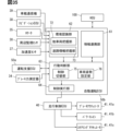
- the autonomous driving ECU 50b is configured with multiple functional units for realizing the autonomous driving function, such as an information linking unit 61, an environment recognition unit 62, an action determination unit 63, and a control execution unit 64 (see Figure 2).
- the information linking unit 61 provides information to the HCU 100 and acquires information from the HCU 100. Through this linking, the autonomous driving ECU 50b and the HCU 100 share the information they each acquire.
- the information linking unit 61 generates control status information that indicates the operating state of the autonomous driving function, and provides the generated control status information to the HCU 100.
- the information linking unit 61 enables the HCU 100 to issue a notification synchronized with the operating state of the autonomous driving function by outputting control status information to the information linking unit 82.
- the information linking unit 61 obtains operation information of the driver or other passengers from the information linking unit 82, and grasps the contents of user operations input to the HMI system 10, etc.
- the environmental recognition unit 62 recognizes environmental information around the vehicle Am.
- the environmental information may be recognized by acquiring it from the in-vehicle communication device 39, the locator 35, the surrounding monitoring sensor 30, etc.
- the environmental information may be recognized by fusing the information acquired by the in-vehicle communication device 39, the locator 35, the surrounding monitoring sensor 30, etc.
- the environment recognition unit 62 has an other vehicle grasping unit 72 and a road information grasping unit 73 as sub-functional units for recognizing the driving environment.
- the other vehicle grasping unit 72 grasps the relative position and relative speed of dynamic targets around the host vehicle, such as other vehicles traveling around the host vehicle Am.
- the other vehicle grasping unit 72 grasps at least the vehicles ahead and behind traveling in the same lane as the host vehicle Am (hereinafter, the host lane), and the side vehicles traveling in the adjacent lane adjacent to the host lane.
- the host vehicle Am is traveling on a road with three or more lanes
- the other vehicle grasping unit 72 grasps the side vehicles traveling in the separated lanes located on the opposite side of the host lane across the adjacent lane.
- the other vehicle grasping unit 72 also grasps other vehicles that are present within the intersection IS that the vehicle Am is about to enter or has entered, and other vehicles that are outside the intersection IS but are present in the vicinity of the intersection IS. Information on these other vehicles is included in the environmental information of the intersection IS.
- the road information grasping unit 73 grasps information related to the road on which the host vehicle Am is traveling.
- the road information grasping unit 73 acquires route information from the navigation ECU 38, it extracts specific points on the road on which the host vehicle Am is scheduled to travel, specifically, intersections IS, branching points (junctions, etc.) on expressways, merging points, and exit points.
- the road information grasping unit 73 grasps congested sections where congestion is occurring, and restricted sections where restrictions are in place due to road construction, etc., for the road on which the host vehicle Am is scheduled to travel.
- the road information grasping unit 73 grasps at least a part of the environmental information of the intersection IS as more detailed road information.
- the environmental information of the intersection IS includes at least one of the following: information on the shape of the intersection IS, information on the roads connecting to the intersection IS, information on the traffic lights CTS of the intersection IS, information on the road markings of the intersection IS, etc.
- the information regarding the shape of the intersection IS may include at least one of the following: the size of the intersection IS, the number of roads connecting to the intersection IS, the direction of the roads connecting to the intersection IS, etc.
- the information regarding the roads connecting to the intersection IS may include at least one of the following: the number of lanes on the connecting road, the role of each lane on the connecting road (left-turn only lane, right-turn only lane, etc.), etc.
- the information regarding the traffic light CTS at the intersection IS may include at least one of the following: the presence or absence of a traffic light CTS, the position and display direction of the traffic light CTS, the presence or absence of an arrow signal ATS in the traffic light CTS, control information for the traffic light CTS, etc.
- Information regarding road markings at an intersection IS may include at least one of the following: the presence and location of a pedestrian crossing, the presence and location of a stop line SL, the presence and location of a guide strip, the presence and location of a safety zone, the presence and location of a traffic control arrow, etc.
- the behavior determination unit 63 cooperates with the driving assistance ECU 50a and the HCU 100 to control the autonomous driving system 50 and the driver's handover of driving.
- the behavior determination unit 63 When the autonomous driving ECU 50b has control of the driving operation, the behavior determination unit 63 generates a planned driving trajectory for the host vehicle Am based on the recognition result of the driving environment by the environment recognition unit 62, and outputs the generated driving trajectory to the control execution unit 64.
- the behavior determination unit 63 has a control switching unit 75 and a vehicle attitude setting unit 76 as sub-functional units for controlling the operating state of the autonomous driving function.
- the control switching unit 75 cooperates with the driving assistance ECU 50a to switch between level 2 driving control, in which the driver is obligated to monitor the surroundings, and driving control in which the driver is not obligated to monitor the surroundings.
- the control switching unit 75 switches between level 3 autonomous driving and level 4 autonomous driving.
- the control switching unit 75 switches the control state of level 3 autonomous driving among multiple control states, including area-limited control (hereinafter, area level 3), which is implemented only when driving within a specific area, and congestion-limited control (hereinafter, congestion level 3), which is implemented only when driving in a congestion.
- area level 3 area-limited control
- congestion level 3 congestion-limited control
- Autonomous driving at level 3 or higher corresponds to the autonomous driving control referred to in this embodiment.
- the vehicle attitude setting unit 76 sets the vehicle attitude when the host vehicle Am stops temporarily during autonomous driving control.
- the vehicle attitude includes the orientation of the vehicle body CB and the angle ⁇ of the steering wheel SW.
- the vehicle attitude setting unit 76 may directly set a numerical value representing the orientation of the vehicle body CB and the angle ⁇ of the steering wheel SW.
- the vehicle attitude setting unit 76 may set the vehicle attitude by selecting the attitude to be adopted from a number of predefined vehicle attitudes.
- right or left turn is a concept that includes right and left turns. In reality, right and left turns cannot be made at the same time, so right or left turn means either a right turn or a left turn.
- the host vehicle Am will turn right at the intersection IS.
- the right or left turn angle ⁇ (here, the angle at which the host vehicle Am turns when turning right) is based on the direction of the road that connects to the intersection IS.
- the right or left turn angle ⁇ can be said to be the angle between the traveling direction TD0 in the host lane EL0 before turning right (in other words, before entering the intersection IS) and the traveling direction TD1 in the host lane EL1 in which the host vehicle travels after turning right.
- the host vehicle Am when the traffic light CTS is displaying a stop signal (e.g., a red light) or when priority is given to other vehicles, such as oncoming vehicles going straight, or to pedestrians, the host vehicle Am must stop temporarily before turning right. This stop may be within an intersection IS, or it may be before entering the intersection IS.
- a stop signal e.g., a red light
- the host vehicle Am must stop temporarily before turning right. This stop may be within an intersection IS, or it may be before entering the intersection IS.
- PA PB
- PC PC
- PD PD
- PE the following five types of vehicle attitudes are assumed when stopping temporarily within an intersection IS: PA, PB, PC, PD, and PE.
- attitude PA is shown in FIG. 5.
- the orientation of the vehicle body CB at the temporary stop is inclined so as to face the traveling direction after the right turn with respect to the own lane EL0 before entering the intersection IS.
- the inclination angle ⁇ (see FIG. 3) of the vehicle body CB with respect to the own lane EL0 is set smaller than the right/left turn angle ⁇ .
- the steering wheel SW is inclined with respect to the vehicle body CB so as to face the traveling direction TD0 after the right turn.
- the sum of the inclination angle ⁇ and the angle ⁇ of the steering wheel SW is set smaller than the right/left turn angle ⁇ .
- Attitude PA is suitable for a relatively large intersection IS, for example when the stop line SL as a road marking in the intersection IS is set at an incline with respect to the own lane EL0 before entering the intersection IS.
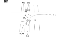
- Position PB is shown in Figure 6.
- the orientation of the vehicle body CB at the temporary stop is inclined so that it faces the direction of travel after a right turn relative to the own lane EL0 before entering the intersection IS.
- the inclination angle ⁇ of the vehicle body CB relative to the own lane EL is set smaller than the angle ⁇ for right or left turns.
- the steering wheel SW is essentially in the same direction as the vehicle body CB. In other words, the angle ⁇ is essentially 0 degrees.
- Position PB is suitable for a relatively large intersection IS, for example when the stop line SL as a road marking within the intersection IS is set at an incline relative to the own lane EL0 before entering the intersection IS.
- Position PC is shown in Figure 7.
- position PC the orientation of the vehicle body CB when temporarily stopping is along the vehicle's own lane EL0 before entering the intersection IS.
- the steering wheel SW is tilted relative to the vehicle body CB so as to face the direction of travel TD1 after the right turn.
- the angle ⁇ of the steering wheel SW is set smaller than the angle ⁇ for right and left turns.
- Position PC is suitable for relatively small intersections IS, for example when there are no stop lines SL as road markings within the intersection IS.
- Position PD is shown in Figure 8.
- Position PD the orientation of the vehicle body CB at the temporary stop is along the vehicle's lane EL0 before entering the intersection IS.
- the steering wheel SW is essentially in the same orientation as the vehicle body CB. In other words, the angle ⁇ of the steering wheel SW is essentially 0 degrees.
- Position PC is suitable for a relatively small intersection IS, for example, when there is no stop line SL as a road marking within the intersection IS.
- Position PE is shown in Figure 9.
- the orientation of vehicle body CB at the temporary stop is tilted so that it faces the opposite direction of travel after turning right with respect to the own lane EL0 before entering intersection IS.
- steering wheel SW is essentially in the same orientation as vehicle body CB. In other words, angle ⁇ of steering wheel SW is essentially 0 degrees.
- the vehicle attitude setting unit 76 of this embodiment determines the vehicle attitude when making a temporary stop based on the size of the intersection IS. Specifically, the vehicle attitude setting unit 76 selects the most appropriate vehicle attitude from the above-mentioned attitudes PA, PB, and PD.
- Position PA the angle ⁇ of the steering wheel SW is set so that it is inclined so that it faces more in the direction of travel after a right turn than the vehicle body CB, while in positions PB and PD, the steering wheel SW faces substantially the same direction as the vehicle body CB.
- Position PA is selected when the intersection IS is larger than a preset threshold. In other words, when the size of the intersection IS is larger than a predetermined threshold, the angle ⁇ is set so that it is inclined so that it faces more in the direction of travel after a right turn than the vehicle body CB. Conversely, at a small intersection IS, if angle ⁇ is set, the overhang of the steering wheel SW may get in the way and disrupt traffic flow, so angle ⁇ is set to 0.
- the size of the intersection IS here may be defined simply by the area of the entire intersection IS.
- the size of the intersection IS may also be defined by the distance between the edge of the road on which the vehicle Am is traveling before turning right or left (in other words, the connection with the intersection IS) and the edge of the road on the opposite side of that road.
- control execution unit 64 cooperates with the cruise control ECU 40 to execute acceleration/deceleration control and steering control of the host vehicle Am according to the driving trajectory generated by the action determination unit 63. Specifically, the control execution unit 64 generates control commands for each driving actuator based on the planned driving trajectory, and sequentially outputs the generated control commands to the cruise control ECU 40.
- the control execution unit 64 When the vehicle attitude setting unit 76 sets the vehicle attitude at the above-mentioned temporary stop, the control execution unit 64 generates a control command such that the operation from the traveling state to the temporary stop is completed in that attitude.
- the angle ⁇ of the steering wheel SW can be changed during a temporary stop.
- the steering wheel SW will rub against the road surface, causing wear on the steering wheel SW and the road surface.
- the host vehicle Am will not be able to restart smoothly.
- the control execution unit 64 therefore calculates the output to each driving actuator 41 so that the angle ⁇ of the steering wheel SW gradually approaches the set position from the driving state to the time of stopping temporarily, and the angle ⁇ becomes the set angle when the operation up to the temporary stop is completed.
- Each driving actuator 41 operates according to a control command based on such calculation, and the series of driving operations before and after the temporary stop at the intersection IS are smoothed.
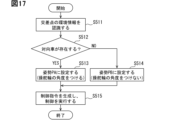
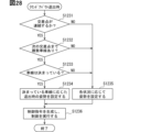
- steps S111 to S118 are performed based on a predetermined trigger by at least one processor of the autonomous driving ECU 50b executing a program. This series of processes is performed when the driving of the host vehicle Am is autonomously controlled and a plan arises for the host vehicle Am to make a right or left turn at an intersection IS.
- the environment recognition unit 62 recognizes the environment information of the intersection IS. After processing S111, the process proceeds to S112.
- the environment recognition unit 62 determines whether the size of the intersection IS is equal to or larger than a preset threshold value Ts1. If the answer is Yes, the process proceeds to S114. If the answer is No, the process proceeds to S113.
- the vehicle attitude setting unit 76 determines whether the size of the intersection IS is equal to or larger than a preset threshold value Ts2.
- the threshold value Ts2 is assumed to be a value smaller than Ts1. If the answer is Yes, proceed to S115. If the answer is No, proceed to S116.
- the vehicle attitude setting unit 76 sets the vehicle attitude when temporarily stopping at the intersection IS to the attitude PA (see FIG. 5). That is, the steering wheel SW is set to an angle ⁇ with respect to the vehicle body CB. After processing S114, the process proceeds to S117.
- the vehicle attitude setting unit 76 sets the vehicle attitude when temporarily stopping at the intersection IS to the attitude PB (see FIG. 6). In other words, the angle ⁇ is not set. After processing S115, the process proceeds to S118.
- the vehicle attitude setting unit 76 sets the vehicle attitude when temporarily stopping at the intersection IS to the attitude PD (see FIG. 8). In other words, the angle ⁇ is not set. After processing in S115, the process proceeds to S118.
- control execution unit 64 calculates the value of the output to the driving actuator 41 that will result in the set angle ⁇ when the temporary stop operation is completed. After processing S117, the process proceeds to S119.
- control execution unit 64 calculates the value of the output to the driving actuator 41 in the same way as during a normal pause. In other words, it calculates the value of the output to the driving actuator 41 such that angle ⁇ is substantially 0 when the pause operation is completed. After processing S118, proceed to S119.
- control execution unit 64 executes control by outputting a control command based on the calculations in S117 and S118 to the driving control ECU 40.
- the series of processes ends with S119.
- the size of the intersection IS may be the area of the intersection IS, and the thresholds Ts1 and Ts2 may be values corresponding to the area.
- the size of the intersection IS may be expressed as data classified into "large,” “medium,” and “small” in the map DB 36 or the like.
- a judgment condition equivalent to a judgment using the threshold Ts1 may be set so that "large” is judged as Yes and “medium” and “small” are judged as No.
- a judgment condition equivalent to a judgment using the threshold Ts2 may be set so that "medium” is judged as Yes and "small” is judged as No.
- the angle ⁇ of the steering wheel SW can be optimized in accordance with the environment of the intersection IS, taking into account the start of the vehicle after the temporary stop. Therefore, after restarting, the vehicle can smoothly complete the right or left turn. This improves convenience in driving.
- the vehicle Am is controlled from traveling to stopping so that the temporary stop operation is completed at the set steering wheel SW angle ⁇ . This makes it possible to improve smoothness when restarting while avoiding the steering wheel SW rubbing against the road surface during the temporary stop.
- the angle ⁇ of the steering wheel SW is set so that the steering wheel SW faces the traveling direction TD1 after turning right or left relative to the direction of the vehicle body CB of the host vehicle Am.
- the angle ⁇ is set only when it is deemed that setting the angle ⁇ will not impede traffic flow, which can promote smooth traffic flow at the intersection IS.
- the angle ⁇ of the steering wheel SW is set so that the direction of the steering wheel SW is aligned with the direction of the vehicle body CB of the host vehicle Am.
- setting the angle ⁇ is avoided, which can promote smooth traffic flow at the intersection IS.
- the orientation of the vehicle body CB of the vehicle Am with respect to the lane EL0 in which the vehicle Am is traveling before turning right or left is also set.
- the autonomous driving ECU 40b in the first embodiment corresponds to the "vehicle control device.”
- the vehicle attitude setting unit 76 corresponds to the "setting unit.”
- the second embodiment is a modification of the first embodiment.
- the second embodiment will be described focusing on the differences from the first embodiment.
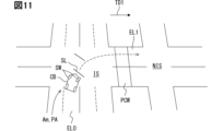
- the vehicle attitude setting unit 76 sets the vehicle attitude at a temporary stop in accordance with information indicating the presence or absence of a crosswalk PCW at the intersection IS and intersection continuity information, which are environmental information of the intersection IS (see FIG. 11).
- the crosswalk PCW here refers to a crosswalk located in the travel direction TD1 after turning right or left, with the center of the intersection IS as the base point.
- the consecutive intersection information is information that the next intersection NIS is present in a consecutive manner in the travel direction TD1 after turning right or left from the intersection IS where a right or left turn is planned.
- consecutive may mean that multiple intersections IS are present within a distance that allows the perimeter monitoring sensor 30 of the host vehicle Am to detect an object ahead.
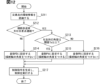
- steps S211 to S217 are performed based on a predetermined trigger by at least one processor of the autonomous driving ECU 50b executing a program. This series of processes is performed when the driving of the host vehicle Am is autonomously controlled and a plan arises for the host vehicle Am to make a right or left turn at an intersection IS.
- the environment recognition unit 62 recognizes the environment information of the intersection IS.
- S211 is the same as S111 in the first embodiment. After processing S211, the process proceeds to S212.
- the vehicle attitude setting unit 76 determines whether or not a pedestrian crossing PCW exists at the intersection IS, or whether or not intersection continuity information exists. If the answer is Yes, proceed to S213. If the answer is No, proceed to S214.
- the vehicle attitude setting unit 76 judges whether the right/left turn angle ⁇ is equal to or greater than a preset threshold value Ta.
- the threshold value Ta may be set to a value greater than 90°.
- the threshold value Ta is set to 100°, 110°, 120°, etc. In other words, if the amount of rotation of the host vehicle Am when turning right or left is large, the steering wheel SW angle ⁇ at the temporary stop is set so that the host vehicle Am can turn right or left with as small a turning radius as possible after restarting. If Yes, proceed to S215. If No, proceed to S216.
- the vehicle attitude setting unit 76 sets the vehicle attitude when temporarily stopping at the intersection IS to the attitude PD (see FIG. 8). In other words, the angle ⁇ is not set. After processing S214, the process proceeds to S217.
- the vehicle attitude setting unit 76 sets the vehicle attitude when temporarily stopping at the intersection IS to attitude PA (see FIG. 5). In other words, an angle ⁇ is set. After processing S215, the process proceeds to S217.
- the vehicle attitude setting unit 76 sets the vehicle attitude when temporarily stopping at the intersection IS to the attitude PB (see FIG. 6). In other words, the angle ⁇ is not set. After processing S216, the process proceeds to S217.
- S217 is the same as S117 to S119 in the first embodiment. S217 ends the series of processes.
- the orientation of the vehicle body CB at a temporary stop is set so that the vehicle body CB of the vehicle Am faces the direction of travel after turning right or left relative to the lane EL0 in which the vehicle Am is traveling before turning right or left.
- This orientation of the vehicle body CB makes it easier for the perimeter monitoring sensor 30 to detect pedestrians and the like on the crosswalk PCW, improving convenience during driving.
- the angle ⁇ of the steering wheel SW is set so that the steering wheel SW faces further toward the traveling direction TD1 after the right or left turn relative to the orientation of the vehicle body CB. This allows the host vehicle Am to turn immediately after restarting, making it easier for the perimeter monitoring sensor 30 to detect pedestrians and the like on the crosswalk PCW from an early stage after restarting.
- the orientation of the vehicle body CB at the temporary stop is set so that the vehicle body CB of the vehicle Am faces the traveling direction TD1 after turning right or left relative to the lane EL0 in which the vehicle Am is traveling before turning right or left.
- This orientation of the vehicle body CB makes it easier for the perimeter monitoring sensor 30 to detect the situation at the next intersection NIS, improving convenience during driving.
- the angle ⁇ of the steering wheel SW is set so that the steering wheel SW faces further toward the traveling direction TD1 after the right or left turn relative to the orientation of the vehicle body CB. In this way, the host vehicle Am can turn immediately after restarting, making it easier for the perimeter monitoring sensor 30 to detect the situation at the next intersection NIS from an early stage after restarting.
- the third embodiment is a modification of the first embodiment.
- the third embodiment will be described focusing on the differences from the first embodiment.
- the vehicle attitude setting unit 76 sets the vehicle attitude at a temporary stop according to the number of lanes of the road on which the host vehicle Am is traveling after turning right or left, which is environmental information of the intersection IS.
- the number of lanes here may be the number of lanes in the traveling direction TD1 of the host vehicle Am, that is, the number of lanes on one side, if the road has lanes EL1 in the traveling direction TD1 of the host vehicle Am and lanes in the opposite direction.
- S311 is the same as S111. After processing S311, the process proceeds to S312.
- the environment recognition unit 62 determines whether the number of lanes on the road after the right or left turn is equal to or greater than a preset threshold Tn1.
- Tn1 may be 3. If Yes, proceed to S314. If No, proceed to S313.
- the vehicle attitude setting unit 76 determines whether the number of lanes on the road after the right or left turn is equal to or greater than a preset threshold value Tn2.
- the threshold value Tn2 is assumed to be a value smaller than Tn1.
- Tn2 may be 2. If Yes, proceed to S315. If No, proceed to S316.
- S314 to 316 are the same as S114 to 116. After each of S314 to 316, the process proceeds to S317. S317 is the same as S217. This series of processes ends with S317.
- the angle ⁇ of the steering wheel SW is set so that the steering wheel SW faces the traveling direction TD1 after the turn relative to the direction of the vehicle body CB of the host vehicle Am.
- setting the angle ⁇ is highly unlikely to disrupt traffic flow. Therefore, by setting the angle ⁇ to smoothly perform right or left turns, it is possible to promote smoother traffic flow at the intersection IS.
- the fourth embodiment is a modification of the first embodiment.
- the fourth embodiment will be described focusing on the differences from the first embodiment.
- the vehicle attitude setting unit 76 sets the vehicle attitude at a temporary stop at an intersection IS where there are multiple lanes for the host vehicle Am to proceed in the travel direction TD1 after turning right or left.
- the multiple lanes here may be two right-turn-only lanes EL0a, EL0b as shown in FIG. 13.
- One of the multiple lanes may be a right-turn-only lane, and the other may be a lane used for both going straight and turning right.
- the vehicle attitude setting unit 76 sets a vehicle attitude that allows the host vehicle Am to make smaller turns in the inner lane EL0a.
- the vehicle attitude setting unit 76 sets a vehicle attitude that allows the host vehicle Am to make larger turns in the outer lane EL0b. In other words, the vehicle attitude setting unit 76 increases the angle ⁇ of the steering wheel SW the further inside the lane used by the host vehicle Am.
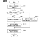
- the behavior determination unit 63 selects alternative lanes to be used for right and left turns when generating a planned driving trajectory for the host vehicle Am. After processing S412, the process proceeds to S413.
- the vehicle attitude setting unit 76 determines whether the lane used for right or left turns is the inside lane EL0a. If Yes, proceed to S414. If No, proceed to S415.
- S414 is the same as S114. After processing S414, the process proceeds to S416. S415 is the same as S115. After processing S415, the process proceeds to S416. S416 is the same as S217. The process ends with S416.
- the setting of the steering wheel SW angle ⁇ differs depending on which of the multiple lanes EL0a, EL0b is to be used.
- the fifth embodiment is a modification of the first embodiment.
- the fifth embodiment will be described focusing on the differences from the first embodiment.
- the vehicle attitude setting unit 76 sets the vehicle attitude at a temporary stop depending on the presence or absence of an oncoming vehicle Bm as another vehicle, which is environmental information at the intersection IS.
- the oncoming vehicle Bm here is an oncoming vehicle that is about to turn right or left at the intersection IS, as shown in FIG. 16.
- the oncoming vehicle Bm is a vehicle that has entered the intersection IS from the opposite side of the host vehicle Am and is about to turn right.
- S511 is the same as S111. After processing S511, the process proceeds to S512.
- the vehicle attitude setting unit 76 determines whether or not the above-mentioned oncoming vehicle Bm is present. If Yes, proceed to S513. If No, proceed to S514.
- S513 is the same as S114. After processing S513, proceed to S515. S514 is the same as S115. After processing S514, proceed to S515. S515 is the same as S217. The series of processes ends with S515.
- the angle ⁇ of the steering wheel SW is set so that the steering wheel SW faces the traveling direction TD1 after turning right or left relative to the orientation of the vehicle body CB of the host vehicle Am.
- the host vehicle Am can turn immediately after restarting, and can adopt a trajectory that allows for tighter turning radius. Therefore, the possibility of contact with the oncoming vehicle Bm can be reduced.
- the sixth embodiment is a modification of the fifth embodiment.
- the sixth embodiment will be described focusing on the differences from the fifth embodiment.
- the behavior determination unit 63 assumes an oncoming vehicle Bm that is about to turn right or left at the intersection IS, and further assumes a predicted driving trajectory TBm for the oncoming vehicle Bm (see FIG. 18). This prediction may be performed only when an oncoming vehicle Bm actually exists. This prediction may also be performed based on the assumption that an oncoming vehicle Bm will appear, even when an oncoming vehicle Bm does not actually exist.
- the vehicle attitude setting unit 76 judges whether or not there is a possibility that the planned travel path TAm of the host vehicle Am will interfere with the predicted travel path TBm of the oncoming vehicle Bm. Then, based on this judgment, the vehicle attitude setting unit 76 sets the vehicle attitude at the temporary stop.
- S611 is the same as S111. After processing S611, the process proceeds to S612.
- the behavior determination unit 63 predicts the traveling trajectory TBm of the oncoming vehicle Bm. After processing S612, the process proceeds to S613.
- the vehicle attitude setting unit 76 determines whether or not there is a possibility that the planned travel path TAm of the host vehicle Am will interfere with the travel path TBm. If the answer is Yes, proceed to S614. If the answer is No, proceed to S615.
- S614 is the same as S114. After processing S614, the process proceeds to S616.
- S615 is the same as S115. After processing S614, the process proceeds to S616.
- S616 is the same as S217. The series of processes ends with S616.
- the posture PC (see FIG. 7) may be set instead of the posture PA.
- the posture PD may be set instead of the posture PB.
- the angle ⁇ of the steering wheel SW is set so that the steering wheel SW faces the traveling direction TD1 after turning right or left relative to the orientation of the vehicle body CB of the host vehicle Am.
- the host vehicle Am can turn immediately after restarting, and the trajectory can be corrected to one that is more maneuverable. Therefore, the possibility of contact with other vehicles at the intersection IS can be reduced.
- the seventh embodiment is a modification of the first embodiment.
- the seventh embodiment will be described focusing on the differences from the first embodiment.
- the vehicle attitude setting unit 76 sets the vehicle attitude at a temporary stop based on information about the traffic lights at the intersection IS.
- information about whether the traffic lights CTS at the intersection IS include an arrow signal ATS related to the right or left turn of the host vehicle Am is used.
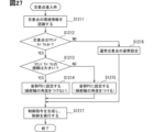
- S711 is the same as S111. After processing S711, the process proceeds to S712.
- the vehicle attitude setting unit 76 determines whether the traffic light CTS includes an arrow signal ATS related to turning right or left of the vehicle Am. If Yes, proceed to S713. If No, proceed to S714.
- the vehicle attitude setting unit 76 sets the vehicle attitude when temporarily stopping at the intersection IS to the attitude PD (see FIG. 8). That is, the direction of the vehicle body CB is set to be aligned with the lane EL0 in which the host vehicle Am is traveling before turning right or left. After processing S713, the process proceeds to S715.
- the vehicle attitude setting unit 76 sets the vehicle attitude when temporarily stopping at the intersection IS to attitude PA (see FIG. 5). That is, the orientation of the vehicle body CB is set to be tilted toward the traveling direction TD1 after the turn, relative to the lane EL0 in which the host vehicle Am is traveling before turning right or left. After processing S714, the process proceeds to S715.
- S715 is the same as S217. This series of processes ends with S715.
- the posture PC may be set instead of the posture PD.
- the posture PB may be set instead of the posture PA.
- the orientation of the vehicle body CB at the temporary stop is set so as to follow the lane EL0 in which the host vehicle Am is traveling before turning right or left.
- the arrow signal ATS there is little need to turn right or left in a hurry due to the timing of the signal change, etc., so the vehicle can turn right or left with plenty of time even in such an orientation.
- the eighth embodiment is a modification of the seventh embodiment.
- the eighth embodiment will be described focusing on the differences from the seventh embodiment.
- the vehicle attitude setting unit 76 determines whether to make a temporary stop at the intersection IS depending on whether the traffic light CTS at the intersection IS includes an arrow signal ATS related to a right or left turn of the host vehicle Am.
- S811 to S812 are the same as S711 to S712. If Yes in S712, proceed to S813. If No, proceed to S814.
- the vehicle attitude setting unit 76 determines not to make a temporary stop at the intersection IS. In other words, since there is no need to set the vehicle attitude itself, the vehicle attitude setting unit 76 omits the process of setting the vehicle attitude. After processing in S813, the process proceeds to S815.
- the vehicle attitude setting unit 76 decides to make a temporary stop at the intersection IS, and sets the vehicle attitude at the temporary stop.
- the vehicle attitude here may be set to any one of attitudes PA to PE. This vehicle attitude may be set based on environmental information, etc. In other words, it is possible to use the processing of other embodiments such as the first to sixth embodiments. After processing of S814, the process proceeds to S815.
- S815 is the same as S217. This series of processes ends with S815.
- the temporary stop at the intersection IS associated with turning right or left is omitted.
- the time that the vehicle Am is in the intersection IS can be shortened, thereby reducing the possibility of contact with other vehicles at the intersection IS.
- the ninth embodiment is a modification of the first embodiment.
- the ninth embodiment will be described focusing on the differences from the first embodiment.
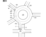
- the vehicle attitude setting unit 76 sets the vehicle attitude at a temporary stop according to the shape of the intersection IS, which is environmental information of the intersection IS. Specifically, the vehicle attitude setting unit 76 calculates the angle at which the host vehicle Am turns when turning right or left, i.e., the right or left turn angle ⁇ , based on the direction of the roads connected to the intersection IS. The vehicle attitude setting unit 76 sets the vehicle attitude at a temporary stop according to the angle ⁇ . For example, in a five-way intersection such as that shown in FIG. 22, when the angle ⁇ exceeds 90°, the vehicle attitude setting unit 76 may set the angle ⁇ of the steering wheel SW to face toward the traveling direction TD1 after the right turn relative to the vehicle body CB.
- the vehicle attitude setting unit 76 also adjusts the angle ⁇ to an angle that causes the amount of rotation of the steering operation unit of the vehicle Am to be less than one rotation after the vehicle Am restarts from a temporary stop until the vehicle completes a right or left turn.
- the angle ⁇ is set to gradually increase as the right or left turn angle ⁇ increases.
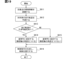
- S911 is the same as S111. After processing S911, the process proceeds to S912.
- the vehicle attitude setting unit 76 calculates the right/left turn angle ⁇ . After processing S912, the process proceeds to S913.
- the vehicle attitude setting unit 76 determines whether the angle ⁇ is equal to or greater than a preset threshold value Ta1. If the answer is Yes, the process proceeds to S915. If the answer is No, the process proceeds to S914.
- the vehicle attitude setting unit 76 determines whether the angle ⁇ is equal to or greater than a preset threshold value Ta2 and the size of the intersection IS is smaller than a preset threshold value Ts. Here, it is assumed that the threshold value Ta2 is smaller than the threshold value Ta1. If the answer is Yes, proceed to S916. If the answer is No, proceed to S917.
- the vehicle attitude setting unit 76 sets the vehicle attitude when temporarily stopping at the intersection IS to attitude PA (see FIG. 5). After processing S915, the process proceeds to S918.
- the vehicle attitude setting unit 76 sets the vehicle attitude when temporarily stopping at the intersection IS to the attitude PC (see FIG. 7). After processing S916, the process proceeds to S918.
- the vehicle attitude setting unit 76 sets the vehicle attitude when temporarily stopping at the intersection IS to the attitude PD (see FIG. 8). After processing S917, the process proceeds to S919.
- the vehicle attitude setting unit 76 adjusts the angle ⁇ of the steering wheel SW within the range of the vehicle attitude set in S915 or S916. Specifically, the vehicle attitude setting unit 76 adjusts the angle ⁇ so that the amount of rotation of the steering operation unit is less than one rotation after the host vehicle Am restarts from a temporary stop until the right or left turn is completed.
- the attitude PA is set, the inclination angle ⁇ of the vehicle body CB may be adjusted along with the angle ⁇ .
- S919 is the same as S217. This series of processes ends with S919.
- the angle ⁇ of the steering wheel SW is set so that the steering wheel SW faces the traveling direction TD1 after the right/left turn relative to the orientation of the vehicle body CB of the host vehicle Am.
- the angle ⁇ is set so that the amount of rotation of the steering operation part of the host vehicle Am is less than one rotation until the right/left turn is completed after the host vehicle Am restarts from a temporary stop. Since the rotation of the steering operation part can be suppressed, the driver's anxiety caused by turning right/left can be reduced.
- the tenth embodiment is a modification of the first embodiment.
- the tenth embodiment will be described focusing on the differences from the first embodiment.
- the host vehicle Am is a large vehicle.
- Large vehicles here include, for example, buses, trucks, trailers, etc. Buses, trucks, and trailers correspond to vehicle types.
- vehicle types may include compact passenger cars, regular passenger cars, etc.
- the vehicle attitude setting unit 76 can select the attitude PE (see FIG. 9) as the vehicle attitude.
- the difference in the inside turning radius becomes large when turning right or left. For this reason, when a large vehicle tries to make a tight turn, there is a possibility that it may hit an object, such as another vehicle or a structure, that is on the inside when turning. In such a case, the host vehicle Am can avoid hitting an object by first steering in the opposite direction to the traveling direction TD1 after turning right or left, and then steering in the traveling direction to make a wide turn.
- the attitude PE is suitable when the host vehicle Am is making a wide turn.
- S1011 is the same as S111. After processing S1011, the process proceeds to S1012.
- the vehicle attitude setting unit 76 determines whether or not a wide turn is necessary when turning right or left. This determination may be made based on, for example, the size of the intersection IS. If the answer is Yes, proceed to S1013. If the answer is No, proceed to S1014.
- the vehicle attitude setting unit 76 sets the vehicle attitude when temporarily stopping at the intersection IS to the attitude PE.
- the orientation of the vehicle body CB is set so that the vehicle body CB faces the opposite side of the traveling direction TD1 after the turn to the lane EL0 in which the host vehicle Am is traveling before turning right or left. After processing S1013, proceed to S1015.
- the vehicle attitude setting unit 76 sets the vehicle attitude when temporarily stopping at the intersection IS to the attitude PD.
- the orientation of the vehicle body CB is set so as to follow the lane EL0 in which the host vehicle Am is traveling before turning right or left.
- S1015 is the same as S217. This series of processes ends with S1015.
- the orientation of the vehicle body CB at the temporary stop is set based on the type of the vehicle Am so that the vehicle body CB of the vehicle Am faces the opposite side of the travel direction TD1 after turning right or left with respect to the lane EL0 in which the vehicle Am is traveling before turning right or left. This makes it possible to prevent collisions by making the vehicle Am turn in a wide direction, even if the vehicle is a large vehicle.
- the eleventh embodiment is a modification of the first embodiment.
- the eleventh embodiment will be described focusing on the differences from the first embodiment.
- the control switching unit 75 switches the driving mode in addition to switching the automation level, etc.
- the driving modes include an eco mode and a comfort mode.
- the driving mode can be switched at the driver's discretion by the driver operating the operation device 26.
- the automated driving system 50 can also switch the driving mode according to predetermined conditions.
- Comfort mode is a mode that allows for comfortable driving and allows for a smooth start when restarting from a temporary stop. For example, in comfort mode, restrictions on driving performance such as engine speed and acceleration are lifted.
- the electric power steering function power assist function for steering
- the electric power steering function may be in an operational state. Therefore, even under autonomous driving control, driving can be performed that maximizes the performance of the host vehicle Am.
- Eco mode is a mode that emphasizes energy costs such as fuel economy and electricity consumption. Restrictions are set for engine speed, acceleration, etc. The upper limit of engine speed is restricted to 1000 rpm, for example. In addition, the electric power steering function may be inactive.
- the control switching unit 75 checks the current driving mode, and if the driving mode is eco mode, switches to comfort mode before restarting. This allows the vehicle to smoothly restart at the intersection IS. Even if a sudden handover of driving from the system to the driver occurs during a temporary stop, the driver can quickly restart and turn right or left.
- S1111 is the same as S111. After processing S1111, the process proceeds to S1112. In S1112, the vehicle attitude setting unit 76 sets the vehicle attitude using environmental information. S1112 corresponds to the processing of S112 to S116 in the first embodiment. After processing S1112, the process proceeds to S1113. S1113 is the same as S217. After processing S1113, the process proceeds to S1114.
- control switching unit 75 determines whether the driving mode is the comfort mode. If the answer is Yes, the process ends, and the host vehicle Am is restarted when it becomes possible to restart. If the answer is No, the process proceeds to S1115.
- control switching unit 75 switches the driving mode to the comfort mode.
- the series of processes ends at S1115, and the host vehicle Am is restarted when it becomes possible to restart.
- the driving mode of the vehicle is switched to a mode that allows for a smooth start. Therefore, the time that the vehicle Am is in the intersection IS can be shortened, and the possibility of contact with other vehicles at the intersection IS can be reduced.
- the twelfth embodiment is a modification of the first embodiment.
- the twelfth embodiment will be described focusing on the differences from the first embodiment.
- the vehicle attitude setting unit 76 determines whether the intersection IS is a roundabout ISR based on environmental information, and sets the attitude of the host vehicle Am appropriate for the roundabout ISR. For example, as shown in FIG. 26, a situation may be considered in which the host vehicle Am passes through a roundabout ISR and then sets a route that passes through a normal intersection (hereinafter, the next intersection) ISN that intersects at one level.
- a roundabout ISR has a shape in which a number of other straight roads are connected radially to a circular road.
- a roundabout ISR may have one lane or multiple lanes on a circular road.
- the roundabout ISR has an outer lane OSL and an inner lane ISL that are parallel to each other.
- the outer lane OSL is a circular lane that is connected to other roads via an entrance ENT and exits PEX, OEX.
- the inner lane ISL is a circular lane that is located radially inward of the outer lane OSL. Normally, the outer lane OSL and the inner lane ISL are capable of changing lanes with each other all around.
- the vehicle attitude setting unit 76 sets the angle ⁇ of the steering wheel SW when the host vehicle Am stops temporarily upon entering the roundabout ISR according to the size of the roundabout ISR. For example, the vehicle attitude setting unit 76 sets the angle ⁇ so that the smaller the size of the roundabout ISR, the more the steering wheel SW faces the direction of travel after turning right or left relative to the direction of the vehicle body CB of the host vehicle Am.
- the size of the roundabout ISR may be expressed, for example, by a numerical value indicating the radius of the outermost periphery of the roundabout ISR. In this case, the angle ⁇ may be calculated by a function of continuous numerical values indicating the size.
- the angle ⁇ may have a negative correlation with the numerical value indicating the radius, for example, and may be inversely proportional.
- the size of the roundabout ISR may be expressed by the number of lanes in the roundabout. In this case, the angle ⁇ is calculated from a discrete numerical value indicating the size.
- the size of the roundabout ISR may be classified into a large roundabout and a small roundabout depending on a combination of conditions such as the radius and the number of lanes.
- the vehicle attitude setting unit 76 may be configured to switch the attitudes PC and PD depending on the size of the roundabout ISR, thereby substantially changing the angle ⁇ .
- the attitudes PA and PB may be switched.
- the vehicle attitude setting unit 76 may set the orientation of the vehicle body CB so that it is substantially perpendicular to the stop line SL that exists when entering the roundabout ISR.
- the vehicle attitude setting unit 76 may set the orientation of the steering wheel SW, i.e., the angle ⁇ , so that the steering wheel SW is substantially perpendicular to the stop line SL that exists when entering the roundabout ISR, regardless of the size of the roundabout as described above.
- the road connecting the roundabout ISR and the next intersection ISN has multiple lanes in each direction.
- the vehicle attitude setting unit 76 sets the angle ⁇ when exiting the roundabout ISR to an angle that is just right for entering the dedicated lane from the lane in which the vehicle is traveling (for example, the outer lane OSL).
- the vehicle attitude setting unit 76 determines whether the intersection IS is a roundabout ISR. If Yes, proceed to S1213. If No, proceed to S1216.
- the vehicle attitude setting unit 76 determines whether the scale of the roundabout ISR is large. If Yes, proceed to S1214. If No, proceed to S1215.
- the vehicle attitude setting unit 76 sets the attitude of the vehicle when it makes a temporary stop upon entering the roundabout ISR to the attitude PD.
- the steering wheel SW is set to an attitude in line with the body CB of the host vehicle Am, and the angle ⁇ is essentially 0.
- the vehicle attitude setting unit 76 sets the attitude of the vehicle when it makes a temporary stop upon entering the roundabout ISR to the attitude PC.
- the steering wheel SW is set to a position facing further in the direction of travel with respect to the vehicle body CB of the host vehicle Am. After processing S1215, the process proceeds to S1217.
- the vehicle attitude setting unit 76 executes attitude setting for a normal intersection. For example, the processes of S112 to S116 may be executed. After the process of S1216, the process proceeds to S1217.
- S1217 is the same as S217. After S1217, the series of processes ends, and the host vehicle Am proceeds to enter the actual intersection IS.
- the processing in FIG. 27 is executed before the host vehicle Am exits the roundabout ISR. It may also be executed in advance before the host vehicle Am enters the roundabout ISR.
- the vehicle attitude setting unit 76 determines whether intersection succession information is present. In other words, it is determined whether the next intersection ISN exists after exiting the roundabout ISR. If Yes, proceed to S1232. If No, proceed to S1235.
- the vehicle attitude setting unit 76 determines whether or not there are multiple lanes L1, L2 in the traveling direction of the host vehicle Am on the road connecting the roundabout ISR and the next intersection ISN. If the answer is Yes, proceed to S1233. If the answer is No, proceed to S1235.
- the vehicle attitude setting unit 76 determines whether or not the lane through which the host vehicle Am will pass has been determined among the multiple lanes L1 and L2. If the answer is Yes, proceed to S1234. If the answer is No, proceed to S1235.
- the vehicle attitude setting unit 76 sets the attitude when exiting the roundabout ISR according to the determined lane position and extension direction. This attitude also includes the steering wheel SW angle ⁇ . The series of processes ends with S1234.
- the vehicle attitude setting unit 76 sets an appropriate attitude depending on each situation.
- the series of processes ends with S1235.
- the angle ⁇ of the steering wheel SW when the host vehicle Am stops temporarily upon entering the roundabout ISR is set according to the size of the roundabout ISR. This makes it possible for the host vehicle Am to execute an appropriate entry operation according to the size, which can promote smooth traffic flow at the roundabout ISR.
- the intersection IS is a roundabout ISR
- the road connecting the roundabout ISR and the next intersection ISN has multiple lanes L1, L2.
- the angle ⁇ of the steering wheel SW when exiting the roundabout ISR is set according to the lane among the multiple lanes L1, L2 that corresponds to the planned direction of travel at the next intersection ISN. This allows the host vehicle Am to travel appropriately from the roundabout ISR to the next intersection ISN, which can promote smooth traffic flow.
- the thirteenth embodiment is a modification of the twelfth embodiment.
- the thirteenth embodiment will be described, focusing on the differences from the twelfth embodiment.
- the vehicle attitude setting unit 76 sets the vehicle attitude of the host vehicle Am within the roundabout ISR. As shown in FIG. 29, the vehicle attitude setting unit 76 can set the vehicle attitude depending on the presence of a moving object traveling within the same roundabout ISR.
- the vehicle attitude setting unit 76 adjusts the angle ⁇ of the steering wheel SW so as to move away from the parallel vehicle Cm.
- the steering wheel SW is angled so that the front portion faces more radially inward than when turning along the curvature of the lane the host vehicle Am is traveling in.
- the steering wheel SW is angled so that the front portion faces more radially outward than when turning along the curvature of the lane the host vehicle Am is traveling in. This angle setting should be done within a range that does not cause the host vehicle Am to deviate from the lane in which it is currently traveling.
- the vehicle attitude setting unit 76 may also change the angle ⁇ of the steering wheel SW for separating the vehicle depending on the size of the parallel vehicle Cm.
- the angle should be set so that the larger the size of the parallel vehicle Cm, the easier it is to immediately separate from the parallel vehicle Cm. That is, for a large parallel vehicle Cm in the situation shown in FIG. 29, the angle is set so that the front portion faces more radially outward than when turning along the curvature of the lane in which the vehicle Am is traveling, and the angle difference from when turning along the curvature is made larger than for a small parallel vehicle Cm.
- the control execution unit 64 may search for a space within the roundabout ISR where the host vehicle Am can be stopped safely, and execute control to stop the host vehicle Am in that space. Through this control, until the host vehicle Am is stopped, the vehicle attitude setting unit 76 sets the angle ⁇ of the steering wheel SW in preparation for the motorcycle MS to cut in on the host vehicle Am.
- the case where a motorcycle MS is present near the host vehicle Am may mean a case where the motorcycle MS is traveling so as to follow behind the host vehicle Am. At this time, the motorcycle MS may be traveling in the same lane as the host vehicle Am, or in an adjacent lane.
- the vehicle attitude setting unit 76 estimates and compares the probability that the motorcycle MS will cut in radially inside of the host vehicle Am and the probability that it will cut in radially outside, based on the environmental information. If the probability of cutting in radially inside is greater than the probability of cutting in radially outside, the steering wheel SW is set at an angle so that the front part faces more radially outward than if the steering wheel SW were to turn along the curvature of the lane in which the host vehicle Am is traveling. This makes it possible to reduce in advance the possibility of contact between the host vehicle Am and the motorcycle MS.
- FIG. 30 An example of a processing method by the autonomous driving ECU 50b in the thirteenth embodiment will be described with reference to the flowchart in FIG. 30.
- the processing in FIG. 30 is executed while the host vehicle Am is traveling within the roundabout ISR.
- the vehicle attitude setting unit 76 determines whether the roundabout ISR has multiple lanes. If Yes, proceed to S1312. If No, proceed to S1314.
- the vehicle attitude setting unit 76 determines whether or not there is a parallel vehicle Cm traveling parallel to the host vehicle Am. If the answer is Yes, proceed to S1313. If the answer is No, proceed to S1314. In S1313, the vehicle attitude setting unit 76 sets an attitude to separate the host vehicle from the parallel vehicle Cm. After processing S1313, proceed to S1318.
- the vehicle attitude setting unit 76 determines whether or not a motorcycle MS is present in the vicinity of the host vehicle Am. If Yes, proceed to S1315. If No, proceed to S1317.
- control execution unit 64 starts searching for a space within the roundabout ISR where the host vehicle Am can stop safely.
- vehicle attitude setting unit 76 sets an attitude of the motorcycle MS in preparation for cutting in until the host vehicle Am stops in the searched space. After processing S1315, the process proceeds to S1318.
- the vehicle attitude setting unit 76 sets the attitude for turning along the curvature of the lane in which the host vehicle Am is traveling as the normal attitude. After processing of S1317, the process proceeds to S1318. S1318 is the same as S1236. The series of processes ends with S1318.
- the angle ⁇ of the steering wheel SW is adjusted to move away from the parallel vehicle Cm. Therefore, the possibility of contact with the parallel vehicle Cm can be reduced.
- the angle ⁇ of the steering wheel SW is set so that the larger the size of the parallel vehicle Cm, the easier it is to immediately separate from the parallel vehicle Cm. Therefore, the possibility of contact with a large parallel vehicle Cm can be reduced.
- the host vehicle Am when the intersection IS is a roundabout ISR, the host vehicle Am is traveling in a lane in the roundabout ISR, and a motorcycle MS is present in the vicinity of the host vehicle Am, the host vehicle Am is stopped in a space in which the host vehicle Am can be stopped. This makes it easier to avoid the occurrence of collisions involving the motorcycle MS being caught in the roundabout ISR.
- the steering wheel SW angle ⁇ is set in preparation for the motorcycle MS cutting in on the host vehicle Am until the host vehicle Am is stopped in the above-mentioned control. Therefore, even if the motorcycle MS cuts in on the host vehicle Am, the possibility of contact can be reduced.
- the fourteenth embodiment is a modification of the fifth embodiment.
- the fourteenth embodiment will be described focusing on the differences from the fifth embodiment.
- the fifteenth embodiment is particularly effective when the traveling direction TD0X in the own lane EL0A in which the host vehicle Am travels before turning right and the traveling direction TD0Y in the oncoming lane EL0B in which the oncoming vehicle Bm travels before turning right are substantially opposite directions (approximately 180 degrees apart), and the right/left turn angles ⁇ of the host vehicle Am and the oncoming vehicle Bm at the intersection IS are substantially equal.
- the steering angle was made different depending on whether or not an oncoming vehicle Bm was present, but in the fourteenth embodiment, the vehicle attitude setting unit 76 acquires information indicating the attitude of the oncoming vehicle Bm as environmental information.
- the other vehicle grasping unit 72 recognizes the attitude of the oncoming vehicle Bm using the surroundings monitoring sensor 30 and generates information indicating the attitude to provide to the vehicle attitude setting unit 76.
- the information indicating the posture includes the orientation of the vehicle body CB and the steering wheel angle ⁇ when the oncoming vehicle Bm stops temporarily at the intersection IS.
- the orientation of the vehicle body CB may be represented by an angle ⁇ with respect to the direction TD0Y
- the steering wheel angle ⁇ may be represented by an angle based on the orientation of the vehicle body CB.
- the vehicle attitude setting unit 76 adjusts the attitude of the host vehicle Am to that of the oncoming vehicle Bm. That is, by imitating the recognized attitude of the oncoming vehicle Bm, the attitude of the host vehicle Am becomes similar to that of the oncoming vehicle Bm. More specifically, the vehicle attitude setting unit 76 replaces the reference for expressing the orientation of the vehicle body CB and steering wheel angle ⁇ of the oncoming vehicle Bm from direction TD0Y to direction TD0X, and then applies the orientation of the vehicle body CB and steering wheel angle ⁇ of the oncoming vehicle Bm to the attitude of the host vehicle Am. At this time, if the error range of the orientation of the vehicle body CB and steering wheel angle ⁇ of the oncoming vehicle Bm is plus or minus 10 degrees, it can be said that the attitude of the host vehicle Am is adjusted to that of the oncoming vehicle Bm.
- S1411 and S1412 are similar to S511 and S512. If Yes in S1412, proceed to S1413. If No, proceed to S1415.
- the vehicle attitude setting unit 76 grasps the attitude of the oncoming vehicle Bm based on the environmental information. In S1414 after processing S1413, the vehicle attitude setting unit 76 adjusts the attitude of the host vehicle Am to the attitude of the oncoming vehicle Bm. After processing S1414, the process proceeds to S1416.
- S1415 is the same as S514. After processing S1415, proceed to S1416. S1416 is the same as S515. This series of processes ends with S1416.
- the environmental information includes information indicating the presence or absence and attitude of an oncoming vehicle Bm attempting to turn right or left at the intersection IS. If an oncoming vehicle Bm is present, the attitude of the host vehicle Am is set according to the attitude of the oncoming vehicle Bm. With this method, an appropriate attitude can be set if the oncoming vehicle Bm is recognized, so it can also be used in cases where the road is poorly recognized.
- the fifteenth embodiment is a modified example of the fifth embodiment.
- the fifteenth embodiment will be described focusing on the differences from the fifth embodiment.
- the angle of the steering wheel is differentiated depending on whether or not an oncoming vehicle Bm is present.
- the direction of the vehicle body CB is differentiated to reduce the possibility of contact with the oncoming vehicle Bm.
- S1511 and S1512 are the same as S511 and S512. If Yes in S1512, proceed to S1513. If No, proceed to S1514.
- the vehicle attitude setting unit 76 sets the vehicle attitude at the temporary stop at the intersection IS to the attitude PB (see FIG. 6). That is, the orientation of the vehicle body CB at the temporary stop is set to an orientation inclined so as to face the traveling direction after the right turn with respect to the own lane EL0 before entering the intersection IS. After processing S1513, proceed to S1515.
- the vehicle attitude setting unit 76 sets the vehicle attitude at the temporary stop at the intersection IS to the attitude PC (see FIG. 7). That is, the orientation of the vehicle body CB at the temporary stop is set to the orientation along the own lane EL0 before entering the intersection IS. After processing of S1514, proceed to S1515. S1515 is the same as S515. The series of processes ends with S1515.
- the environmental information includes information indicating whether or not an oncoming vehicle Bm is about to turn right or left at the intersection IS.
- the angle of the vehicle body CB of the vehicle Am relative to the vehicle's own lane EL0 before entering the intersection IS is set to an angle such that the vehicle body CB is tilted more toward the traveling direction after turning right or left than when there is no oncoming vehicle Bm. This makes it easier to turn right or left at the intersection IS without colliding with the oncoming vehicle Bm.
- the sixteenth embodiment is a modification of the first embodiment.
- the sixteenth embodiment will be described focusing on the differences from the first embodiment.
- the vehicle attitude setting unit 76 acquires information about the driver of the vehicle Am.
- the driver information may be registered in the HCU 100, for example, and acquired through the information linking unit 61.
- personal authentication is performed through the HCU 100, making it possible to identify the current driver.
- the driver information may include the driver's age, gender, and attributes.
- the driver's attributes may include manual driving experience, driving score, and the like, and may further include personality, etc.
- the vehicle attitude setting unit 76 then sets the steering wheel SW angle ⁇ when stopping temporarily at an intersection IS according to the driver information.
- the angle ⁇ of the steering wheel SW when temporarily stopping at an intersection IS is set to an angle that is in line with the direction of the vehicle body of the vehicle Am.
- the driving level may be a driving score, or a parameter calculated based on age, driving score, and experience. Note that instead of a driver with a low driving level in accelerator operation, a driver who is inexperienced at driving may be extracted.
- the vehicle attitude setting unit 76 acquires information about the driver. After processing S1611, the process proceeds to S1612.
- the vehicle attitude setting unit 76 determines whether the driver of the vehicle Am is inexperienced. If the answer is Yes, proceed to S1613. If the answer is No, proceed to S1614.
- the vehicle attitude setting unit 76 sets the vehicle attitude when temporarily stopping at the intersection IS to the attitude PB or the attitude PD (see Figures 6 and 8). In other words, the setting is made without the angle ⁇ . After processing S1613, the process proceeds to S1615.
- the vehicle attitude setting unit 76 sets the vehicle attitude when temporarily stopping at the intersection IS to attitude PA or attitude PC (see Figures 5 and 7). In other words, an angle ⁇ is set.
- the process proceeds to S1615.
- the process of S1615 is the same as S217. The series of processes ends with S1615.
- the host vehicle Am is configured to be able to take over driving with the driver of the host vehicle Am when autonomous control of driving cannot be continued. Then, the angle ⁇ of the steering wheel SW when temporarily stopping at an intersection IS is set according to the acquired driver information. Therefore, it is possible to set an appropriate posture for the driver in preparation for a driving handover in an emergency, etc.
- the angle ⁇ of the steering wheel SW when temporarily stopping at an intersection IS is set to an angle that is aligned with the direction of the vehicle body CB of the vehicle Am.
- the seventeenth embodiment is a modification of the first embodiment.
- the seventeenth embodiment will be described focusing on the differences from the first embodiment.
- the vehicle system 1 further includes a braking force measuring device 3M that measures the braking force of the host vehicle Am, as shown in FIG. 35.
- the braking force measuring device 3M monitors the operating state of the brake actuator 41a and the actual braking distance of the host vehicle Am corresponding to this operating state.
- the braking force measuring device 3M measures the effectiveness of the brakes of the host vehicle Am from the relationship between this operating state and the braking distance.
- the braking force measuring device 3M sequentially provides the measurement results to the action determination unit 63 of the autonomous driving ECU 50b. This allows the vehicle attitude setting unit 76 to grasp the usual effectiveness of the brakes of the host vehicle Am.
- the road information grasping unit 73 also grasps the condition and inclination of the road on which the host vehicle Am is traveling.
- the vehicle attitude setting unit 76 sets the angle ⁇ of the steering wheel SW when the host vehicle stops temporarily at the intersection IS according to at least one of the road condition and inclination.
- the vehicle attitude setting unit 76 determines whether or not the road conditions make it easy for slippage to occur, and if so, sets the angle ⁇ of the steering wheel SW so that the direction is unlikely to cause slippage in relation to the incline.
- conditions in which slippage is likely to occur include conditions where there is snow on the road surface or where the road surface is frozen.
- the angle should be set so that the steering wheel SW is oriented in a different direction, preferably substantially perpendicular, to the direction in which the road gradient is at its maximum.
- the vehicle attitude setting unit 76 may also use information about the grip force of the steering wheel SW, such as the measurement results from the braking force measuring device 3M, to determine the direction in which slippage is unlikely to occur. This may be performed regardless of whether or not the situation is such that slippage is likely to occur.
- the vehicle attitude setting unit 76 estimates the possibility of slippage occurring for each angle of the steering wheel SW by calculating it based on information related to road conditions and grip force.
- the angle pitch of this calculation may be, for example, 10 degree increments or 15 degree increments.
- inclination information may also be used in this calculation. Then, the vehicle attitude setting unit 76 sets the final steering wheel SW angle ⁇ to the angle at which the possibility of slippage occurring is low (for example, the lowest) from the calculation results for each angle.
- S1711 is the same as S111. After processing S1711, the process proceeds to S1712.
- the vehicle attitude setting unit 76 determines whether the road surface is snowy or icy based on the environmental information. If Yes, proceed to S1713. If No, proceed to S1717.
- the vehicle attitude setting unit 76 acquires road inclination information.
- the vehicle attitude setting unit 76 acquires information regarding the grip force of the host vehicle Am. After processing of S1714, the process proceeds to S1715.
- the vehicle attitude setting unit 76 calculates the possibility of slipping for each angle.
- the angle ⁇ of the steering wheel SW is set in a direction in which slipping is unlikely to occur based on the calculation result. After processing S1716, the process proceeds to S1718.
- the vehicle attitude setting unit 76 sets the vehicle to the standard attitude PA (see FIG. 5). After processing S1717, the process proceeds to S1718.
- S1718 is the same as S217. The series of processes ends with S1718.
- the environmental information includes information related to road conditions.
- the steering wheel SW angle ⁇ when stopping temporarily at an intersection IS is set according to the conditions. This makes it possible to prevent trouble caused by road conditions.
- the environmental information further includes information regarding the inclination of the road. Then, when the conditions are such that slippage is likely to occur on the road, the angle ⁇ of the steering wheel SW is set so that the direction of the inclination makes it difficult for slippage to occur. The angle of the steering wheel SW that matches the inclination can suppress the occurrence of slippage.
- the possibility of slippage occurring for the provisional steering wheel SW angle setting is estimated based on information regarding road conditions and the grip force of the steering wheel SW, and the final steering wheel SW angle is set based on this possibility. This makes it possible to suppress the occurrence of slippage.
- various conditions can be used as the judgment conditions for setting the vehicle attitude.
- the vehicle attitude setting unit 76 may set the vehicle attitude based on judgment conditions that combine the shape of the intersection IS, the presence or absence of an oncoming vehicle Bm, information about the traffic light CTS, and the like.
- the vehicle attitude setting unit 76 may also set the vehicle attitude based on judgment using a trained model constructed using a neural network or the like.
- vehicle control by the autonomous driving ECU 50b can be optimized as appropriate in accordance with the road traffic laws, customs, etc. of each country and region.
- the assumption was made that vehicles drive on the left side of the road in accordance with Japan's Road Traffic Law, but vehicle control can be optimized on the assumption that vehicles drive on the right side of the road.
- the setting of the vehicle attitude when stopping temporarily at an intersection IS may be applied by an application used for driving assistance at automation level 2.
- the vehicle attitude setting unit 76 may set the vehicle attitude as the driver performs a temporary stop operation.
- intersection IS for which the vehicle attitude is to be set may be various intersections.
- the vehicle attitude setting unit 76 may set the vehicle attitude at a temporary stop at a complex intersection including an intersection with a grade separation, a roundabout, etc.
- the vehicle equipped with the above-described vehicle system 1 is not limited to a general private passenger car, but may be a rental car vehicle, a manned taxi vehicle, a ride-sharing vehicle, etc.
- the steering wheel SW in the vehicle may be the rear wheels or all four wheels.
- control unit and the method described in the present disclosure may be realized by a dedicated computer comprising a processor programmed to execute one or more functions embodied in a computer program.
- the device and the method described in the present disclosure may be realized by a dedicated hardware logic circuit.
- the device and the method described in the present disclosure may be realized by one or more dedicated computers configured by a combination of a processor that executes a computer program and one or more hardware logic circuits.
- the computer program may be stored on a computer-readable non-transient tangible recording medium as instructions executed by the computer.
- a vehicle control device that autonomously controls driving of a host vehicle (Am), An environment recognition unit (62) that recognizes environmental information at an intersection (IS); A vehicle control device comprising a setting unit (76) that uses the environmental information to set an angle ( ⁇ ) of a steering wheel (SW) of the vehicle when the vehicle makes a temporary stop in conjunction with turning right or left at the intersection.
- the vehicle control device described in Technical Idea 1 further includes a control execution unit (64) that executes control of the vehicle from driving to the temporary stop so that the temporary stop operation is completed at the steering wheel angle set by the setting unit.
- a control execution unit (64) that executes control of the vehicle from driving to the temporary stop so that the temporary stop operation is completed at the steering wheel angle set by the setting unit.
- the environmental information includes a size of the intersection, The vehicle control device described in Technical Idea 1 or 2, in which the setting unit sets the angle of the steering wheel so that the steering wheel faces the direction of travel (TD1) after the right or left turn relative to the direction of the vehicle body (CB) of the vehicle when the size of the intersection is equal to or greater than a predetermined threshold value.
- the environmental information includes information indicating the presence or absence of a pedestrian crossing (PCW) at the intersection, A vehicle control device described in any one of Technical Ideas 1 to 4, wherein the setting unit sets the orientation of the vehicle body at the temporary stop when a crosswalk is present so that the body of the vehicle faces the direction of travel after the right/left turn with respect to the lane (EL0) in which the vehicle is traveling before the right/left turn.
- PCW pedestrian crossing
- EL0 lane
- the environmental information includes intersection continuity information in which the intersection and a next intersection (NIS) are present in succession in a traveling direction after the right or left turn, A vehicle control device described in any one of Technical Ideas 1 to 6, wherein the setting unit sets the orientation of the vehicle body at the temporary stop when the intersection continuity information is present so that the body of the vehicle faces the direction of travel after the right/left turn with respect to the lane in which the vehicle is traveling before the right/left turn.
- NIS next intersection
- the environmental information includes a number of lanes of a road on which the host vehicle is traveling after making the right or left turn, A vehicle control device described in any one of technical ideas 1 to 8, wherein the setting unit sets the angle of the steering wheel so that the steering wheel faces the direction of travel after the right or left turn relative to the orientation of the vehicle body when the number of lanes is equal to or greater than a predetermined threshold value.
- ⁇ Technical Concept 10> A vehicle control device as described in any one of Technical Ideas 1 to 9, wherein the setting unit is configured to set the angle of the steering wheel differently depending on which of a plurality of lanes (EL0a, EL0b) is to be used at an intersection where there are a plurality of lanes for the vehicle to proceed in the direction of travel after the right or left turn.
- EL0a, EL0b lanes
- the environmental information includes information indicating the presence or absence of an oncoming vehicle (Bm) that is about to turn right or left at the intersection, A vehicle control device described in any one of Technical Ideas 1 to 10, in which the setting unit sets the angle of the steering wheel so that, when an oncoming vehicle is present, the steering wheel faces the direction of travel after the right or left turn relative to the orientation of the vehicle body of the vehicle.
- Bm oncoming vehicle
- a vehicle control device described in any one of Technical Ideas 1 to 10 in which the setting unit sets the angle of the steering wheel so that, when an oncoming vehicle is present, the steering wheel faces the direction of travel after the right or left turn relative to the orientation of the vehicle body of the vehicle.
- ⁇ Technical Concept 12> When there is a possibility that a driving trajectory (TAm) planned for the vehicle may interfere with a driving trajectory (TBm) predicted for an oncoming vehicle attempting to turn right or left at the intersection, A vehicle control device described in any one of technical ideas 1 to 11, wherein the setting unit sets the angle of the steering wheel so that the steering wheel faces the direction of travel after the right/left turn relative to the direction of the vehicle body of the vehicle.
- the environmental information includes information regarding a traffic light (CTS) at the intersection; A vehicle control device described in any one of Technical Ideas 1 to 12, in which the setting unit sets the direction of the body of the vehicle at the temporary stop so that it follows the lane in which the vehicle is traveling before making the right or left turn when the traffic light includes an arrow signal (ATS) related to the right or left turn of the vehicle.
- CTS traffic light
- ATS arrow signal
- the environmental information includes information regarding a traffic light at the intersection, A vehicle control device described in any one of Technical Ideas 1 to 12, in which the setting unit decides to omit the temporary stop at an intersection associated with the right or left turn when the traffic light includes an arrow signal related to the right or left turn of the vehicle.
- ⁇ Technical Concept 15> A vehicle control device described in any one of Technical Ideas 1 to 14, wherein the setting unit sets the angle of the steering wheel so that the steering wheel faces the direction of travel after the right-left turn relative to the orientation of the vehicle body when the right-left turn angle ( ⁇ ) of the vehicle at which the vehicle turns right-left is equal to or greater than a predetermined threshold value.
- ⁇ Technical Concept 16> A vehicle control device described in any one of technical ideas 1 to 15, in which the setting unit sets the angle of the steering wheel so that the amount of rotation of the steering operation unit of the vehicle is less than one rotation after the vehicle restarts from the temporary stop until the right or left turn is completed.
- the environmental information includes a size of the intersection, The vehicle control device described in Technical Idea 1 or 2, wherein the setting unit sets the orientation of the vehicle's body at the temporary stop so that it is aligned with the lane in which the vehicle is traveling before making the right or left turn when the size of the intersection is smaller than a predetermined threshold and the angle at which the vehicle turns when making the right or left turn is equal to or greater than a predetermined threshold, and sets the angle of the steering wheel so that the steering wheel faces the direction of travel after the right or left turn relative to the orientation of the vehicle body.
- ⁇ Technical Concept 20> A vehicle control device described in any one of Technical Ideas 1 to 19, wherein the setting unit sets, together with the angle of the steering wheel, the orientation of the body of the vehicle relative to the lane in which the vehicle is traveling before turning right or left.
- ⁇ Technical Concept 24> The vehicle control device described in any one of Technical Ideas 1 and 21 to 23, wherein the intersection is a roundabout (ISR) having a plurality of lanes (OSL, ISL), the setting unit adjusts the angle of the steering wheel so as to move away from the parallel vehicle (Cm) when the vehicle is traveling in one of the plurality of lanes and there is a parallel vehicle (Cm) in a lane adjacent to that lane.
- ISR roundabout
- OSL, ISL parallel vehicle
- a vehicle control device as described in any one of Technical Ideas 1 and 21 to 25, further comprising a control execution unit (64) that stops the vehicle in a space where the vehicle can be stopped when the intersection is a roundabout (ISR), the vehicle is traveling in a lane within the roundabout, and a motorcycle is present in the vicinity of the vehicle.
- a control execution unit (64) that stops the vehicle in a space where the vehicle can be stopped when the intersection is a roundabout (ISR), the vehicle is traveling in a lane within the roundabout, and a motorcycle is present in the vicinity of the vehicle.
- the environmental information includes information indicating the presence and posture of an oncoming vehicle (Bm) that is about to turn right or left at the intersection,
- the vehicle control device according to Technical Idea 1 or 2, wherein the setting unit sets the attitude of the host vehicle in accordance with the attitude of the oncoming vehicle when the oncoming vehicle is present.
- the environmental information includes information indicating the presence or absence of an oncoming vehicle (Bm) that is about to turn right or left at the intersection,
- the vehicle control device described in Technical Idea 1 or 2 in which the setting unit sets an angle ( ⁇ ) of the orientation of the vehicle's body with respect to the vehicle's own lane (EL0A) before entering the intersection when the oncoming vehicle is present such that the vehicle body is tilted more toward the direction of travel after turning right or left than when the oncoming vehicle is not present.
- the vehicle is configured to be able to take over driving with a driver of the vehicle when autonomous control of driving cannot be continued,
- the vehicle control device according to Technical Idea 1 or 2, wherein the setting unit acquires information about the driver and sets the angle of the steering wheel when the vehicle stops temporarily at the intersection in accordance with the information about the driver.
- the environmental information includes information regarding road conditions, The vehicle control device according to Technical Idea 1 or 2, wherein the setting unit sets the angle of the steering wheel when the vehicle is to stop temporarily at the intersection depending on the condition.
- the environmental information further includes information regarding a slope of a road;
- the vehicle control device according to technical idea 32, wherein the setting unit sets the angle of the steering wheel so that the angle is in a direction in which slippage is unlikely to occur relative to the inclination when the conditions are such that slippage is likely to occur on the road.
Landscapes
- Engineering & Computer Science (AREA)
- Transportation (AREA)
- Mechanical Engineering (AREA)
- Automation & Control Theory (AREA)
- Human Computer Interaction (AREA)
- Chemical & Material Sciences (AREA)
- Combustion & Propulsion (AREA)
- Physics & Mathematics (AREA)
- Mathematical Physics (AREA)
- Traffic Control Systems (AREA)
Priority Applications (3)
| Application Number | Priority Date | Filing Date | Title |
|---|---|---|---|
| CN202480013120.7A CN120752164A (zh) | 2023-02-17 | 2024-02-15 | 车辆控制装置、车辆控制程序以及车辆控制方法 |
| JP2025501206A JPWO2024172117A1 (https=) | 2023-02-17 | 2024-02-15 | |
| US19/295,035 US20250376167A1 (en) | 2023-02-17 | 2025-08-08 | Vehicle control device, vehicle control program, and vehicle control method |
Applications Claiming Priority (2)
| Application Number | Priority Date | Filing Date | Title |
|---|---|---|---|
| JP2023-022998 | 2023-02-17 | ||
| JP2023022998 | 2023-02-17 |
Related Child Applications (1)
| Application Number | Title | Priority Date | Filing Date |
|---|---|---|---|
| US19/295,035 Continuation US20250376167A1 (en) | 2023-02-17 | 2025-08-08 | Vehicle control device, vehicle control program, and vehicle control method |
Publications (1)
| Publication Number | Publication Date |
|---|---|
| WO2024172117A1 true WO2024172117A1 (ja) | 2024-08-22 |
Family
ID=92419948
Family Applications (1)
| Application Number | Title | Priority Date | Filing Date |
|---|---|---|---|
| PCT/JP2024/005298 Ceased WO2024172117A1 (ja) | 2023-02-17 | 2024-02-15 | 車両制御装置、車両制御プログラム及び車両制御方法 |
Country Status (4)
| Country | Link |
|---|---|
| US (1) | US20250376167A1 (https=) |
| JP (1) | JPWO2024172117A1 (https=) |
| CN (1) | CN120752164A (https=) |
| WO (1) | WO2024172117A1 (https=) |
Citations (7)
| Publication number | Priority date | Publication date | Assignee | Title |
|---|---|---|---|---|
| WO2006114977A1 (ja) * | 2005-04-20 | 2006-11-02 | Equos Research Co., Ltd. | 制御装置、及び、車両 |
| JP2007145253A (ja) * | 2005-11-29 | 2007-06-14 | Equos Research Co Ltd | 制御装置及び車両 |
| JP2014214661A (ja) * | 2013-04-25 | 2014-11-17 | ダイハツ工業株式会社 | 車両用制御装置 |
| JP2018192825A (ja) * | 2017-05-12 | 2018-12-06 | 株式会社デンソー | 車両の自動運転制御システム |
| JP2019202722A (ja) * | 2018-05-25 | 2019-11-28 | 株式会社デンソー | 車両制御装置 |
| WO2021006210A1 (ja) * | 2019-07-10 | 2021-01-14 | 日立オートモティブシステムズ株式会社 | 電子制御装置 |
| JP2022178291A (ja) * | 2021-05-20 | 2022-12-02 | フォルシアクラリオン・エレクトロニクス株式会社 | 旋回支援装置 |
-
2024
- 2024-02-15 JP JP2025501206A patent/JPWO2024172117A1/ja active Pending
- 2024-02-15 WO PCT/JP2024/005298 patent/WO2024172117A1/ja not_active Ceased
- 2024-02-15 CN CN202480013120.7A patent/CN120752164A/zh active Pending
-
2025
- 2025-08-08 US US19/295,035 patent/US20250376167A1/en active Pending
Patent Citations (7)
| Publication number | Priority date | Publication date | Assignee | Title |
|---|---|---|---|---|
| WO2006114977A1 (ja) * | 2005-04-20 | 2006-11-02 | Equos Research Co., Ltd. | 制御装置、及び、車両 |
| JP2007145253A (ja) * | 2005-11-29 | 2007-06-14 | Equos Research Co Ltd | 制御装置及び車両 |
| JP2014214661A (ja) * | 2013-04-25 | 2014-11-17 | ダイハツ工業株式会社 | 車両用制御装置 |
| JP2018192825A (ja) * | 2017-05-12 | 2018-12-06 | 株式会社デンソー | 車両の自動運転制御システム |
| JP2019202722A (ja) * | 2018-05-25 | 2019-11-28 | 株式会社デンソー | 車両制御装置 |
| WO2021006210A1 (ja) * | 2019-07-10 | 2021-01-14 | 日立オートモティブシステムズ株式会社 | 電子制御装置 |
| JP2022178291A (ja) * | 2021-05-20 | 2022-12-02 | フォルシアクラリオン・エレクトロニクス株式会社 | 旋回支援装置 |
Also Published As
| Publication number | Publication date |
|---|---|
| CN120752164A (zh) | 2025-10-03 |
| JPWO2024172117A1 (https=) | 2024-08-22 |
| US20250376167A1 (en) | 2025-12-11 |
Similar Documents
| Publication | Publication Date | Title |
|---|---|---|
| US11970158B2 (en) | Driving assistance system, driving assistance device, and driving assistance method for avoidance of an obstacle in a traveling lane | |
| CN111583711B (zh) | 行为控制方法和行为控制设备 | |
| CN105172792B (zh) | 车辆的行驶控制装置 | |
| US10994735B2 (en) | Vehicle control device | |
| US11449060B2 (en) | Vehicle, apparatus for controlling same, and control method therefor | |
| JP6817413B2 (ja) | 車両制御装置 | |
| US20250360926A1 (en) | Automated driving control device | |
| JP7533536B2 (ja) | 自動運転制御装置及び自動運転制御プログラム | |
| US20200223441A1 (en) | Vehicle, apparatus for controlling same, and control method therefor | |
| JP2023073198A (ja) | 車両制御装置 | |
| US20250360927A1 (en) | Automated driving control device, storage medium storing automated driving control program, and automated driving control method | |
| CN113401056A (zh) | 显示控制装置、显示控制方法以及计算机可读取存储介质 | |
| US20250360925A1 (en) | Automated driving control device, storage medium storing automated driving control program, and automated driving control method | |
| JP7795926B2 (ja) | 運転支援装置 | |
| JP2018090063A (ja) | 車両制御システム | |
| WO2023032626A1 (ja) | 自動運転制御装置及び自動運転制御プログラム | |
| WO2024172117A1 (ja) | 車両制御装置、車両制御プログラム及び車両制御方法 | |
| US20250360946A1 (en) | Automated driving control device, storage medium storing automated driving control program, and automated driving control method | |
| US20250360947A1 (en) | Vehicle control device, storage medium storing vehicle control program, and vehicle control method | |
| JP7635328B1 (ja) | 車両の制御装置 | |
| US20250346180A1 (en) | Driving assistance system, driving assistance method, and driving assistance program | |
| US20250360948A1 (en) | Vehicle control device, storage medium storing vehicle control program, and vehicle control method | |
| WO2024236934A1 (ja) | 車両用制御装置及び車両用制御方法 | |
| WO2025225395A1 (ja) | 自動運転制御装置及び自動運転制御方法 | |
| JP2024166026A (ja) | 車両用制御装置及び車両用制御プログラム |
Legal Events
| Date | Code | Title | Description |
|---|---|---|---|
| 121 | Ep: the epo has been informed by wipo that ep was designated in this application |
Ref document number: 24756957 Country of ref document: EP Kind code of ref document: A1 |
|
| ENP | Entry into the national phase |
Ref document number: 2025501206 Country of ref document: JP Kind code of ref document: A |
|
| WWE | Wipo information: entry into national phase |
Ref document number: 2025501206 Country of ref document: JP |
|
| WWE | Wipo information: entry into national phase |
Ref document number: 202480013120.7 Country of ref document: CN |
|
| NENP | Non-entry into the national phase |
Ref country code: DE |
|
| WWP | Wipo information: published in national office |
Ref document number: 202480013120.7 Country of ref document: CN |
|
| 122 | Ep: pct application non-entry in european phase |
Ref document number: 24756957 Country of ref document: EP Kind code of ref document: A1 |