WO2024171801A1 - ゴルフクラブ非接触自動測定方法とその装置 - Google Patents
ゴルフクラブ非接触自動測定方法とその装置 Download PDFInfo
- Publication number
- WO2024171801A1 WO2024171801A1 PCT/JP2024/002911 JP2024002911W WO2024171801A1 WO 2024171801 A1 WO2024171801 A1 WO 2024171801A1 JP 2024002911 W JP2024002911 W JP 2024002911W WO 2024171801 A1 WO2024171801 A1 WO 2024171801A1
- Authority
- WO
- WIPO (PCT)
- Prior art keywords
- shaft
- laser light
- golf club
- digital camera
- center line
- Prior art date
- Legal status (The legal status is an assumption and is not a legal conclusion. Google has not performed a legal analysis and makes no representation as to the accuracy of the status listed.)
- Ceased
Links
Images


Classifications
-
- G—PHYSICS
- G01—MEASURING; TESTING
- G01B—MEASURING LENGTH, THICKNESS OR SIMILAR LINEAR DIMENSIONS; MEASURING ANGLES; MEASURING AREAS; MEASURING IRREGULARITIES OF SURFACES OR CONTOURS
- G01B11/00—Measuring arrangements characterised by the use of optical techniques
- G01B11/26—Measuring arrangements characterised by the use of optical techniques for measuring angles or tapers; for testing the alignment of axes
-
- A—HUMAN NECESSITIES
- A63—SPORTS; GAMES; AMUSEMENTS
- A63B—APPARATUS FOR PHYSICAL TRAINING, GYMNASTICS, SWIMMING, CLIMBING, OR FENCING; BALL GAMES; TRAINING EQUIPMENT
- A63B53/00—Golf clubs
-
- G—PHYSICS
- G01—MEASURING; TESTING
- G01B—MEASURING LENGTH, THICKNESS OR SIMILAR LINEAR DIMENSIONS; MEASURING ANGLES; MEASURING AREAS; MEASURING IRREGULARITIES OF SURFACES OR CONTOURS
- G01B11/00—Measuring arrangements characterised by the use of optical techniques
- G01B11/14—Measuring arrangements characterised by the use of optical techniques for measuring distance or clearance between spaced objects or spaced apertures
-
- G—PHYSICS
- G01—MEASURING; TESTING
- G01B—MEASURING LENGTH, THICKNESS OR SIMILAR LINEAR DIMENSIONS; MEASURING ANGLES; MEASURING AREAS; MEASURING IRREGULARITIES OF SURFACES OR CONTOURS
- G01B11/00—Measuring arrangements characterised by the use of optical techniques
- G01B11/24—Measuring arrangements characterised by the use of optical techniques for measuring contours or curvatures
- G01B11/25—Measuring arrangements characterised by the use of optical techniques for measuring contours or curvatures by projecting a pattern, e.g. one or more lines, moiré fringes on the object
-
- G—PHYSICS
- G06—COMPUTING OR CALCULATING; COUNTING
- G06T—IMAGE DATA PROCESSING OR GENERATION, IN GENERAL
- G06T7/00—Image analysis
- G06T7/60—Analysis of geometric attributes
-
- A—HUMAN NECESSITIES
- A63—SPORTS; GAMES; AMUSEMENTS
- A63B—APPARATUS FOR PHYSICAL TRAINING, GYMNASTICS, SWIMMING, CLIMBING, OR FENCING; BALL GAMES; TRAINING EQUIPMENT
- A63B2102/00—Application of clubs, bats, rackets or the like to the sporting activity ; particular sports involving the use of balls and clubs, bats, rackets, or the like
- A63B2102/32—Golf
Definitions
- the present invention relates to a non-contact automatic golf club measurement method and device that measures loft angle, lie angle, face progression (FP), etc., without contact. More specifically, the present invention relates to a non-contact automatic golf club measurement method and device that is used in the production process, etc., and can measure the loft angle, lie angle, face progression (FP), etc. of golf clubs and determine whether they are being produced according to design in a short time and without contact.
- the measuring device described in the above Patent Document 1 cannot accurately measure angles, etc., using images from a CCD camera.
- the measuring device described in Patent Document 2 requires two cameras, a laser slit projector, and two lighting devices, making the device large.
- the golf club shaft needs to be set vertically during measurement, it takes skill and time to operate the measuring device, and is therefore not suitable for use in a production process.
- An object of the present invention is to provide a non-contact automatic measuring method and device for golf clubs, which allows even an unskilled operator to measure the dimensions of a golf club.
- Another object of the present invention is to provide a non-contact automatic golf club measurement method and device that can measure the dimensions of a golf club quickly and accurately using a simple device.
- the non-contact automatic measurement method for golf clubs according to the present invention 1 comprises the steps of: a laser light emitter that emits a laser light, which is a slit light, onto the golf club; and a digital camera that captures an image of the reflected light of the irradiated laser light.
- a shaft holding step of placing and holding the shaft of the golf club a shaft image capturing step of capturing a shaft image based on an outer shape of the shaft; a shaft centerline calculation step of determining a shaft centerline of the shaft from the shaft image; a head image capturing step of capturing a head image of the head of the golf club; a scoreline calculation step of determining a scoreline of the golf club from the head image; a reference face surface calculation step of determining a reference face surface from the head image;
- the method is characterized in that one or more selected from a lie angle, a loft angle, and a face progression are determined from the shaft center line, the score lines, and the reference face surface.
- the non-contact automatic measurement method for golf clubs of the present invention 2 is characterized in that, in the non-contact automatic measurement method for golf clubs of the present invention 1, the shaft image capture process and the head image capture process involve moving the laser light emitter and the digital camera, or the golf club, in the direction of the center line of the shaft to irradiate the slit light.
- the non-contact automatic measurement method for golf clubs of the present invention 3 is characterized in that, in the second invention, the direction of irradiation of the laser light is perpendicular to the center line of the shaft, and the shooting direction of the digital camera forms an angle with the direction of irradiation of the laser light.
- the non-contact automatic measuring device for golf clubs according to the present invention 1 is a laser light emitter that emits a laser light, which is a slit light, onto the golf club; a digital camera that captures reflected light of the irradiated laser light as an image; a plurality of positioning blocks for horizontally mounting and holding the shaft of the golf club; The laser light irradiator and the digital camera are moved relative to each other along a shaft center line that is the center of the shaft placed on the positioning block.
- the non-contact automatic golf club measuring device of the present invention 2 is characterized in that in the non-contact automatic golf club measuring device of the present invention 1, the relative movement means is a means for mounting the laser light emitting device and the digital camera, or the golf club, on a moving platform and moving it on a guide rail by a screw drive.
- the non-contact automatic golf club measuring device of the present invention 3 is the non-contact automatic golf club measuring device of the present invention 2, wherein the laser light irradiator is installed at an angle position to irradiate from a direction perpendicular to the center line of the shaft,
- the digital camera is characterized in that its photographing direction is at an angle to the irradiation direction of the laser light.
- the non-contact automatic golf club measurement method and device of the present invention has the advantage that even an unskilled operator can measure the specifications of a golf club, and that the specifications of a golf club can be measured quickly and accurately with a simple device.
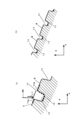
- FIG. 1 is an explanatory diagram showing an outline of the measurement principle of a non-contact automatic measuring device 1 for golf clubs according to a first embodiment of the present invention.
- Figure 2 is an explanatory diagram explaining the principle of determining the position of the shaft centerline from the circular outer shape of the shaft, where Figure 2(a) is an example of a photograph captured by capturing a slit light of the shaft, Figure 2(b) is a diagram showing the shaft center calculated from the photograph of the shaft, and Figure 2(c) is an example of an actual photograph showing an example of the shaft being imaged at regular intervals.
- FIG. 3 is an explanatory diagram showing a cross section of a scoreline when a slit light is irradiated onto the scoreline, where FIG.
- FIG. 3(a) is an enlarged cross section
- FIG. 3(b) is a cross section for explaining the position of the scoreline.
- FIG. 4 is a diagram showing the measurement of the face surface to determine the score lines and their positions.
- FIG. 4(a) shows the measured positions (black dots) drawn on the face surface
- FIG. 4(b) is an explanatory diagram based on the long score lines.
- FIG. 5 is an explanatory diagram showing a method for calculating a reference face surface, where FIG. 5(a) is a diagram explaining a method for dividing the measurement data used as a reference, and FIG. 5(b) is a diagram explaining the reference face surface.
- FIG. 6 is an explanatory diagram for explaining the principle of FP measurement.
- FIG. 5 is a diagram explaining a method for dividing the measurement data used as a reference
- FIG. 5(b) is a diagram explaining the reference face surface.
- FIG. 6 is an explanatory diagram for explaining the principle of FP measurement.
- FIG. 7 is a block diagram showing an outline of a control system for controlling the non-contact automatic golf club measuring device.
- FIG. 8 is an explanatory diagram showing the specifications of the club head, where FIG. 8(a) is a front view and FIG. 8(b) is a left side view.
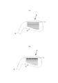
- FIG. 9 is a diagram showing the appearance of a non-contact automatic measuring device 50 for golf clubs according to the second embodiment of the present invention.
- FIG. 1 is an explanatory diagram showing an outline of the measurement principle of the golf club non-contact automatic measuring device 1.
- Two mounting blocks 3 are fixed at an interval on a measuring device body 2 of the golf club non-contact automatic measuring device 1, and a V block 4 is fixed on the mounting block 3.
- the V block 4 is a general one, and in this example, is a steel rectangular parallelepiped base with a V groove at an angle of 90 degrees.
- the two V blocks 4 are arranged and fixed so that the V grooves are linear and on the same plane.
- the shaft 6 of a cylindrical golf club 5 is placed on the two V blocks 4, and the shaft 6 is positioned and supported by the V groove. Since the shaft 6 is placed on the V groove, the shaft center line 7 does not move and the shaft 6 is always positioned at a predetermined position in the width direction of the V groove.
- a laser light irradiator 25 that irradiates laser light is disposed on the movable stage 16.
- This laser light irradiator 25 outputs a linear laser light for measurement, called slit light 26, in the Y-axis direction.
- the slit light 26 is irradiated from above the shaft 6 in a direction approximately perpendicular to the shaft center line 7. Note that this approximately perpendicular direction does not have to be exactly 90 degrees, and can be corrected by calculation, so the concept of approximately perpendicular in this invention includes angles before and after the perpendicular direction.
- the slit light 26 is irradiated from above in a direction perpendicular to the shaft center line 7 of the cylindrical shaft 6, so that its shape appears on the surface of the shaft 6 as a linear semicircle.
- a digital camera 27 is mounted on the movable stage 16 to photograph this semicircle.
- the center line 28, which is the optical axis of the lens of the digital camera 27, is set at an angular position that forms an angle ⁇ (acute angle) with the slit light 26.
- the center line of the slit light 26 of the laser light irradiator 25 and the center line 28 of the lens of the digital camera 27 move along the shaft center line 7.
- This movement is performed by starting and rotating the servo motor 20, and moving the laser light irradiator 25 and the digital camera 27 mounted on the movable stage 16 together along the shaft center line 7.
- the slit light 26 emitted from the laser light irradiator 25 is irradiated onto the shaft 6, and the slit light 26 appears on the surface of the shaft 6 as a linear semicircle.
- This semicircular irradiated light is photographed by a digital camera 27 from the direction of the slit light 26 at an angle ⁇ , so its shape is captured as a semi-ellipse (more precisely, an arc of an ellipse) (see FIG. 2(a)).
- the position of the shaft centerline 7 is calculated from this semi-ellipse using a calculation method described below.
- FIG. 8 is an explanatory diagram of the specifications of the club head, FIG. 8(a) is a front view, and FIG. 8(b) is a left side view.
- the lie angle ⁇ is the angle between the shaft center line 7 and the score line 11.
- the angle between the face surface 9, which is a substantially flat surface of the club head 8, and the surface including the shaft center line 7 (also parallel to the score line 11) is the loft angle ⁇ .
- the face surface 9 on which the score line 11 is formed is not necessarily flat in its entirety, so the face surface 9 in this embodiment is a surface measured and calculated by a method to be described later.
- the face progression (FP) refers to the distance between the surface including the shaft center line 7 (also parallel to the score line 11) and a surface that is parallel to this surface and includes the tip end side of the leading edge 14 (the most forward side of the face surface 9).
- FIGS. 2(a) to 2(c) are explanatory diagrams explaining the principle of determining the position of the shaft center line 7 from the circular shape of the shaft 6, where Figure 2(a) is an example of a photograph taken by capturing a slit light of the shaft, Figure 2(b) is a diagram in which the shaft center line is calculated from the photograph of the shaft, and Figure 2(c) is an example of a photograph taken at regular intervals in the axial direction of the shaft.
- the photographed image has a semi-elliptical shape, as shown in FIG. 2(a).
- This semi-elliptical arc which is two-dimensional data (pixels), is converted into three-dimensional data (x, y, z space) (in mm units).
- This data conversion is based on the data of a calibration performed in advance.
- This calibration geometrically relates the three-dimensional position (x, y, z space) of the outer diameter of the shaft 6 to the two-dimensional data of the semi-elliptical arc data, which is the photographed image.
- FIG. 3 is an explanatory diagram when slit light is irradiated onto the scoreline, and is a cross-sectional view of the scoreline, FIG. 3(a) is an enlarged cross-sectional view, and FIG. 3(b) is a cross-sectional view explaining the position of the scoreline. As shown in FIG.
- the slit light 26 is continuously irradiated onto the scoreline 11 on the face surface 9, which is placed at an angle ⁇ with the slit light 26.
- each position (three-dimensional spatial position) that is each measurement point is specified from the reflected light of the slit light 26 that is reflected.
- the measurement points (black dots in the figure) on the face surface 9 at this time are close to the previous measurement point and are therefore identified consecutively, but the side walls 12 of the scoreline 11 are in a blind spot, so the light is reflected from the groove bottom 13 rather than from the side walls 12. That is, the slit light 26 is irradiated while moving in the x-axis direction (FIG. 3), and the reflected light is measured at regular intervals. When the slit light 26 reaches the position of the scoreline 11, it is reflected from the groove bottom 13 rather than from the side walls 12.
- the step difference (y-axis direction) of the measured value at this time is also a numerical step in the y-axis direction, so this measurement position (black dots in the figure) is determined to be the position of the groove bottom 13 of the scoreline 11 (FIG. 3(b)). This measurement is performed on the entire face surface 9.
- the criterion for determining that the measurement position is the step position of the scoreline 11 is its size (y-axis direction). This size is set based on the dimensions and tolerances set in the design, and is determined by the differential value, threshold value, measurement data of the actual production product, etc.
- FIG. 4 shows the scoreline positions determined by measuring the face surface using the above-mentioned scoreline 11 detection method, with FIG. 4(a) showing the determined positions (black dots) drawn on the face surface, and FIG. 4(b) being an explanatory diagram based on the long scoreline.
- Each point (black dot) in FIG. 4(a) is the scoreline 11 identified by the above-mentioned algorithm.
- the scoreline 11 is formed as a number of parallel grooves, and is detected as shown in the pointillism drawing in FIG. 4(a).
- a straight line is determined from each of these measurement points (black dots) using the least squares method, and this straight line is set as the scoreline 11. At this time, only the longest straight line among the straight lines is adopted as the scoreline 11.
- the length of the measured scoreline 11 is not necessarily the same, so here, the average value of the vectors of the multiple scorelines 11 is set as the inclination of the scoreline 11.
- the coordinates (x, y, z axis positions) of both ends of the straight line calculated to be the longest among the scorelines 11 are set as both ends of the scoreline 11.
- the center position of the averaged scoreline 11 in the length direction is obtained, and the face surface 9 is divided into two partition surfaces 30, which are surfaces that are perpendicular to the scoreline 11 and have a constant width interval, with this center position as the center (see FIG. 5(a)).
- the scoreline 11 can be said to be a surface normal to the partition surface 30.
- a band-shaped reference face surface 31 is determined by a method described later (see FIG. 5(b)). From the band-shaped face surface 9 divided by the two partition surfaces 30, only points whose shape change amount is determined to be less than a preset threshold value by a differential value or the like are extracted.
- a plane is calculated from the extracted point group by the least squares method to obtain the reference face surface 31.
- the reference face surface 31 is determined, the loft angle ⁇ formed with the shaft center line 12 described above can be calculated, and therefore the reference face surface 31 is determined.
- FIG. 6 is an explanatory diagram explaining the principle of FP measurement.
- a shaft centerline plane 32 that is parallel to the scoreline 11 described above and includes the shaft centerline 7 is defined.
- the normal distance of each measurement point 33 of the measured leading edge 14 is calculated from the shaft centerline plane 32.
- the measurement point that is the furthest normal distance from each measurement point 33 is set as the FP point, and this is defined as the face progression (FP) (see FIG. 8).
- FIG. 7 is a block diagram showing an outline of a control system 40 for controlling the golf club non-contact automatic measuring device 1.
- the control device 41 of the control system 40 is a known sequence control means consisting of a CPU (Central Processing Unit), RAM, ROM, auxiliary storage device, display means, input means, various output means, etc.
- a position signal is sent from a position detection sensor 43 to the control device 41 via an interface (I/F) 42.
- the position detection sensor 43 is for detecting the position of the moving table 16 in the x-axis direction. Specifically, it is a rotary encoder for detecting the rotation of the servo motor 20.
- the servo motor 20, the laser irradiator 25, and the digital camera 27 are connected to the control device 41 via the interface (I/F) 42, and the control device 41 controls the ON/OFF, etc. of these.
- the image processing and calculation processing described above are performed by the control device 41 using software stored in the CPU (Central Processing Unit), RAM, ROM, auxiliary storage device, etc., and these specific processes are known techniques, so their explanations will be omitted.
- FIG. 9 is an external view showing the external appearance of a non-contact automatic golf club measuring device 50 according to a second embodiment of the present invention.
- the non-contact automatic golf club measuring device 50 is an example of a structure in which the golf club 5 is moved.
- the measuring device main body 51 which is a housing, is a rectangular box-shaped hollow inside and has an opening on the front. This prevents light, dust, etc.
- An automatic stage mechanism 52 which is a unit that moves the golf club 5, is arranged on the bottom plate of the measuring device main body 51.
- the unitized automatic stage mechanism 52 including its movement control device, is well known and commercially available.
- a rail (not shown) is disposed and fixed on the base 53.
- a movable base 56 is movably mounted on the rail by a linear bearing (not shown).
- a servo motor 54 is disposed at the end of the rail.
- a feed screw (not shown), which is a ball screw, is connected to the output shaft of the servo motor 54.
- the feed screw is a screw for converting rotational motion into linear motion to drive the moving stage 56.
- a ball nut (not shown) that screws into the feed screw is fixedly disposed on the moving stage 56. Therefore, when the servo motor 54 is started to rotate its main shaft, the moving stage 56 moves along the rail (x-axis direction).
- a laser light irradiator 58 that irradiates laser light and a digital camera 59 are fixedly disposed on the measuring device main body 51 above the automatic stage mechanism 52.
- the scoreline 11 described above, more precisely the reference face surface 31, was determined at the position of the groove bottom 13.
- the position of one corner 11b of the scoreline 11 may be determined as the scoreline.
- the scoreline 11 is detected in pairs with the other corner 11a across the groove bottom 13, so that the detection can be performed accurately. That is, the scoreline 11 can be determined by the measurement value of the scoreline 11 based on the differential value in the Y-axis direction of the corner 11a and the differential value of the side wall 12 of the corner 11b, so that the measurement value can be determined accurately.
- the reference face surface 31 described above was a strip, but it may be a circle so as to include the sweet spot 34 (see FIG.
- the lie angle ⁇ is the angle between the scoreline 11 and the ground contact surface of the shaft center line 7 when the scoreline 11 is placed parallel to the ground contact surface and the surface including the shaft center line 7 is placed vertically. Therefore, since the positions of the shaft center line 7 and the score lines 11 can be measured, the lie angle ⁇ can also be measured.
- the shooting direction of the digital camera 27 mentioned above forms an angle ⁇ with the irradiation direction of the slit light 26.
- This angle ⁇ can be any angle as long as it does not cause diffuse reflection.
- the slit light 26 emitted by the laser light irradiator 25 is emitted from a direction perpendicular to the shaft center line 7. It is not limited to this perpendicular direction, and the irradiation direction can be any angle as long as it does not cause diffuse reflection.
- the above-mentioned golf club non-contact automatic measurement device 1 has been explained assuming that it is mainly used for measurements during the production process of golf clubs, but it can also be used for golf clubs that are in use or on sale and are used at golf courses, golf driving ranges, golf equipment shops, etc.
Landscapes
- Physics & Mathematics (AREA)
- General Physics & Mathematics (AREA)
- Engineering & Computer Science (AREA)
- Computer Vision & Pattern Recognition (AREA)
- Health & Medical Sciences (AREA)
- General Health & Medical Sciences (AREA)
- Physical Education & Sports Medicine (AREA)
- Geometry (AREA)
- Theoretical Computer Science (AREA)
- Length Measuring Devices By Optical Means (AREA)
- Golf Clubs (AREA)
- Image Analysis (AREA)
Priority Applications (2)
| Application Number | Priority Date | Filing Date | Title |
|---|---|---|---|
| KR1020257028530A KR20250150002A (ko) | 2023-02-13 | 2024-01-30 | 골프 클럽 비접촉 자동 측정 방법과 그 장치 |
| CN202480012126.2A CN120659650A (zh) | 2023-02-13 | 2024-01-30 | 高尔夫球杆非接触式自动测量方法及装置 |
Applications Claiming Priority (2)
| Application Number | Priority Date | Filing Date | Title |
|---|---|---|---|
| JP2023-019868 | 2023-02-13 | ||
| JP2023019868A JP7701071B2 (ja) | 2023-02-13 | 2023-02-13 | ゴルフクラブ非接触自動測定方法 |
Publications (1)
| Publication Number | Publication Date |
|---|---|
| WO2024171801A1 true WO2024171801A1 (ja) | 2024-08-22 |
Family
ID=92421723
Family Applications (1)
| Application Number | Title | Priority Date | Filing Date |
|---|---|---|---|
| PCT/JP2024/002911 Ceased WO2024171801A1 (ja) | 2023-02-13 | 2024-01-30 | ゴルフクラブ非接触自動測定方法とその装置 |
Country Status (5)
| Country | Link |
|---|---|
| JP (1) | JP7701071B2 (https=) |
| KR (1) | KR20250150002A (https=) |
| CN (1) | CN120659650A (https=) |
| TW (1) | TWI895957B (https=) |
| WO (1) | WO2024171801A1 (https=) |
Citations (6)
| Publication number | Priority date | Publication date | Assignee | Title |
|---|---|---|---|---|
| JPS6079206A (ja) * | 1983-10-06 | 1985-05-07 | Nippon Gakki Seizo Kk | ゴルフ用クラブヘツドの測定法 |
| JPH10337344A (ja) * | 1997-06-09 | 1998-12-22 | Fuitsuto:Kk | ゴルフクラブのライ角・ロフト角測定方法およびその装置ならびにその測定手順を実行させるためのプログラムを記録したコンピュータ読み取り可能な記録媒体 |
| JP2002005623A (ja) * | 2000-06-27 | 2002-01-09 | Roland Dg Corp | レーザー光を用いた変位測定方法 |
| JP2003102876A (ja) * | 2001-09-28 | 2003-04-08 | Mizuno Corp | ゴルフクラブシャフトのねじれ特性測定装置 |
| US20040221464A1 (en) * | 2003-05-08 | 2004-11-11 | David Burney | Apparatus and method for measuring and adjusting golf club loft and lie |
| US20120073383A1 (en) * | 2010-09-29 | 2012-03-29 | Daniel You | Multi function test method and station for golf club shafts |
Family Cites Families (4)
| Publication number | Priority date | Publication date | Assignee | Title |
|---|---|---|---|---|
| JP2526142B2 (ja) | 1989-12-27 | 1996-08-21 | 日ノ出エンジニアリング株式会社 | ゴルフクラブの溝角及びシャフト角の測定装置 |
| KR100337344B1 (ko) | 1999-10-01 | 2002-05-21 | 이계안 | 자동 변속기 차량의 급발진 방지 시스템 |
| TW200944772A (en) * | 2008-04-16 | 2009-11-01 | Advanced Int Multitech Co Ltd | Golf club properties measurement device and the method using the same |
| CN112747698A (zh) * | 2019-10-29 | 2021-05-04 | 复盛应用科技股份有限公司 | 高尔夫球杆头测量方法 |
-
2023
- 2023-02-13 JP JP2023019868A patent/JP7701071B2/ja active Active
-
2024
- 2024-01-30 CN CN202480012126.2A patent/CN120659650A/zh active Pending
- 2024-01-30 TW TW113103421A patent/TWI895957B/zh active
- 2024-01-30 WO PCT/JP2024/002911 patent/WO2024171801A1/ja not_active Ceased
- 2024-01-30 KR KR1020257028530A patent/KR20250150002A/ko active Pending
Patent Citations (6)
| Publication number | Priority date | Publication date | Assignee | Title |
|---|---|---|---|---|
| JPS6079206A (ja) * | 1983-10-06 | 1985-05-07 | Nippon Gakki Seizo Kk | ゴルフ用クラブヘツドの測定法 |
| JPH10337344A (ja) * | 1997-06-09 | 1998-12-22 | Fuitsuto:Kk | ゴルフクラブのライ角・ロフト角測定方法およびその装置ならびにその測定手順を実行させるためのプログラムを記録したコンピュータ読み取り可能な記録媒体 |
| JP2002005623A (ja) * | 2000-06-27 | 2002-01-09 | Roland Dg Corp | レーザー光を用いた変位測定方法 |
| JP2003102876A (ja) * | 2001-09-28 | 2003-04-08 | Mizuno Corp | ゴルフクラブシャフトのねじれ特性測定装置 |
| US20040221464A1 (en) * | 2003-05-08 | 2004-11-11 | David Burney | Apparatus and method for measuring and adjusting golf club loft and lie |
| US20120073383A1 (en) * | 2010-09-29 | 2012-03-29 | Daniel You | Multi function test method and station for golf club shafts |
Also Published As
| Publication number | Publication date |
|---|---|
| JP2024114229A (ja) | 2024-08-23 |
| TW202440199A (zh) | 2024-10-16 |
| CN120659650A (zh) | 2025-09-16 |
| KR20250150002A (ko) | 2025-10-17 |
| JP7701071B2 (ja) | 2025-07-01 |
| TWI895957B (zh) | 2025-09-01 |
Similar Documents
| Publication | Publication Date | Title |
|---|---|---|
| CN107860331B (zh) | 形状测定装置、形状测定方法、构造物制造方法 | |
| US5118192A (en) | System for 3-D inspection of objects | |
| JPS60185108A (ja) | 物体を無接触測定する方法および装置 | |
| CN114160961A (zh) | 用于标定激光加工参数的系统和方法 | |
| JP2014126381A (ja) | 形状測定装置、構造物製造システム、形状測定方法、構造物製造方法、及び形状測定プログラム | |
| JP6417645B2 (ja) | 表面形状測定装置のアライメント方法 | |
| JPH04254706A (ja) | 対象物表面を無接触式に測定する方法並びにこの方法を実施する座標測定機械 | |
| JP5776282B2 (ja) | 形状測定装置、形状測定方法、及びそのプログラム | |
| JP2022171677A5 (https=) | ||
| JPH08208376A (ja) | ルツボの計測方法 | |
| JP2000018921A (ja) | 寸法測定方法及び装置 | |
| JPH08278117A (ja) | 作業対象面に対する作業器具の姿勢制御装置とこれを有するルツボの計測装置および塗装装置 | |
| JP7772822B2 (ja) | 三次元計測装置 | |
| JP7701071B2 (ja) | ゴルフクラブ非接触自動測定方法 | |
| JP3293830B2 (ja) | 物体の幾何学パラメータを測定および計算する装置および方法 | |
| JP2011085402A (ja) | 表面性状測定機 | |
| US11933597B2 (en) | System and method for optical object coordinate determination | |
| CN121876859A (zh) | 检测设备及其同轴度的测量方法 | |
| JPH085344A (ja) | 3次元形状入力装置 | |
| CN113197591A (zh) | 一种摄影平台 | |
| JP2000326082A (ja) | レーザ加工機 | |
| CN210664355U (zh) | 一种利用视觉识别获取肠衣直径的机构 | |
| CN218725184U (zh) | 一种基于机器视觉的激光头来料入库自动检测系统 | |
| JPH0854234A (ja) | 三次元座標位置計測方法 | |
| JPH0660807B2 (ja) | 光の中心位置の高精度計測方法 |
Legal Events
| Date | Code | Title | Description |
|---|---|---|---|
| 121 | Ep: the epo has been informed by wipo that ep was designated in this application |
Ref document number: 24756652 Country of ref document: EP Kind code of ref document: A1 |
|
| WWE | Wipo information: entry into national phase |
Ref document number: 202480012126.2 Country of ref document: CN |
|
| ENP | Entry into the national phase |
Ref document number: 1020257028530 Country of ref document: KR Free format text: ST27 STATUS EVENT CODE: A-0-1-A10-A15-NAP-PA0105 (AS PROVIDED BY THE NATIONAL OFFICE) |
|
| NENP | Non-entry into the national phase |
Ref country code: DE |
|
| WWP | Wipo information: published in national office |
Ref document number: 202480012126.2 Country of ref document: CN |
|
| WWP | Wipo information: published in national office |
Ref document number: 1020257028530 Country of ref document: KR |
|
| 122 | Ep: pct application non-entry in european phase |
Ref document number: 24756652 Country of ref document: EP Kind code of ref document: A1 |