WO2024171237A1 - 故障箇所推定装置、故障箇所推定方法および故障箇所推定プログラム - Google Patents
故障箇所推定装置、故障箇所推定方法および故障箇所推定プログラム Download PDFInfo
- Publication number
- WO2024171237A1 WO2024171237A1 PCT/JP2023/004677 JP2023004677W WO2024171237A1 WO 2024171237 A1 WO2024171237 A1 WO 2024171237A1 JP 2023004677 W JP2023004677 W JP 2023004677W WO 2024171237 A1 WO2024171237 A1 WO 2024171237A1
- Authority
- WO
- WIPO (PCT)
- Prior art keywords
- link
- fault
- address
- network
- addresses
- Prior art date
- Legal status (The legal status is an assumption and is not a legal conclusion. Google has not performed a legal analysis and makes no representation as to the accuracy of the status listed.)
- Ceased
Links
Images







Classifications
-
- H—ELECTRICITY
- H04—ELECTRIC COMMUNICATION TECHNIQUE
- H04L—TRANSMISSION OF DIGITAL INFORMATION, e.g. TELEGRAPHIC COMMUNICATION
- H04L41/00—Arrangements for maintenance, administration or management of data switching networks, e.g. of packet switching networks
- H04L41/06—Management of faults, events, alarms or notifications
Definitions
- the present invention relates to a fault location estimation device, a fault location estimation method, and a fault location estimation program.
- IP Internet Protocol
- IP conversion devices IP-STP (Signal Transfer Point), SG (Signaling Gateway), etc.
- switches that transfer common channel signals over the IP network, routers, and other network devices (transfer devices), etc.
- MTP Common Channel link failure
- MTP3 signal route failure/detouring control
- This alarm includes information related to the common channel signaling, such as the signal link number and point code, but does not include the virtualization configuration or network configuration of the device. Furthermore, with the shift to IP and virtualization of the common channel signaling network, even a single hardware failure is likely to cause multiple link failures, generating a large number of alarms.
- Non-Patent Document 2 when a fault occurs in a network, a method has been disclosed for estimating the location of the fault based on if-then rules in which a group of events such as alarms that occur for each fault pattern are the if part, and the cause of the fault and its location are the then part (see Non-Patent Document 2). Note that when a rule corresponding to the fault pattern that has occurred is not registered, this if-then rule is learned by inputting fault cause information by the maintenance worker.
- Patent Document 1 when the technique described in Patent Document 1 is used, in the case of a link failure in a common channel signaling network on an IP network, communication continues by processing such as signal detouring, making it difficult to estimate the location of the failure based on a failure report from a user. Furthermore, the method described in Non-Patent Document 2 estimates the location of a fault from a specific fault pattern based on if-then rules, and therefore it is difficult to estimate the location of a fault in cases where a single fault causes similar alarms to be generated simultaneously from multiple devices, such as in a common channel signaling network.
- the present invention was made in consideration of these points, and its objective is to provide a method for estimating the location of a fault from multiple alarms that occur in a common channel signaling network on an IP network.
- the fault location estimation device is a fault location estimation device that estimates a fault location in a common channel signaling network configured on an IP network, and is characterized by comprising: a log collection unit that collects logs from devices on the common channel signaling network; a link fault extraction unit that extracts a signaling link fault alarm indicating a link fault of a common channel signaling system from the log; an IP address conversion unit that refers to link information in which link numbers of common channel links are previously associated with IP addresses at both ends of the common channel link, and converts the link numbers of the common channel link included in the signaling link fault alarm into the IP addresses at both ends of the common channel link; an address counting unit that counts the IP addresses converted by the IP address conversion unit; and an estimation unit that estimates the fault location based on the number of alarm occurrences of the IP addresses counted by the address counting unit.
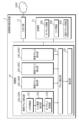
- FIG. 1 is a diagram showing the overall configuration of a failure location estimating system configured by connecting a failure location estimating device according to an embodiment of the present invention to an IP network.
- FIG. 1 is a diagram illustrating an example of the configuration of a common channel signaling network configured on an IP network.
- 1 is a block diagram showing a configuration of a failure location estimation device according to an embodiment of the present invention
- 4 is a diagram showing an example of IP address information stored in a storage unit of the failure location estimating device according to the present embodiment
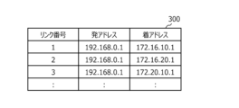
- FIG. 4 is a diagram showing an example of link information stored in a storage unit of the failure location estimating device according to the present embodiment;
- FIG. 1 is a diagram showing the overall configuration of a failure location estimating system configured by connecting a failure location estimating device according to an embodiment of the present invention to an IP network.
- FIG. 1 is a diagram illustrating an example of the configuration of a common channel signaling network configured on an IP network.
- 1 is a block diagram showing a configuration of a
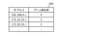
- FIG. 11 is a diagram showing an example of a count result of IP addresses counted by an address counting unit of the failure point estimating device according to the present embodiment.
- FIG. 4 is a diagram for explaining a time period during which an address tallying unit of the failure point estimating device according to the present embodiment tally IP addresses;
- FIG. 4 is a diagram for explaining a process in which an estimation unit of the failure point estimation device according to the present embodiment estimates a failure point from a counting result of IP addresses.
- FIG. FIG. 2 is a sequence diagram showing the flow of the entire process executed by the failure location estimating device according to the present embodiment.
- FIG. 1 is a diagram showing a part of the configuration of a common channel signaling network configured in an IP network.
- FIG. 11 is a diagram showing an example of IP address information corresponding to FIG. 10.
- FIG. 11 is a diagram showing an example of link information for host name #a-1 in FIG.
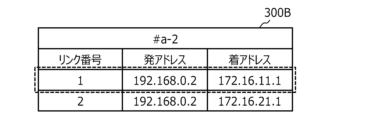
- FIG. 11 is a diagram showing an example of link information for host name #a-2 in FIG.
- FIG. 11 is a diagram showing an example of link information for host name #10-1 in FIG.
- FIG. 11 is a diagram showing an example of link information for host name #11-1 in FIG.
- FIG. 11 is a diagram illustrating an example of aggregated address information.
- FIG. 2 is a hardware configuration diagram showing an example of a computer that realizes the functions of the failure location estimation device according to the present embodiment.
- the fault location estimation device collects logs from devices that make up a common channel signaling network in a common channel signaling network configured on an IP network.
- the fault location estimation device then extracts signaling link failure alarms from the collected logs and converts the link numbers described in the signaling link failure alarms into corresponding IP addresses.
- the fault location estimation device tallies the IP addresses and, based on the number of alarm occurrences, which is the number of IP addresses, estimates in which device of the devices that make up the common channel signaling network, or in which network equipment (transfer equipment) on the IP network through which they pass, the failure has occurred.
- FIG. 1 shows the overall configuration of a fault location estimating system 3000 configured by configuring a common channel signaling network 2000 on an IP network 1000 and further connecting a fault location estimating device 1 according to this embodiment to the IP network 1000.
- the IP network 1000 is made up of a plurality of network devices 70, 70, . . . , 70, such as switches and routers, which transfer data.
- the common channel signaling network 2000 is a PSTN (Public Switched Telephone Network) of the common channel signaling system.
- a common channel signaling network 2000 configured on an IP network 1000 includes a metal accommodation device 20, an IP conversion device 30, an IP-STP 40, an SG 50, and an SIP server 60. A plurality of these devices are connected within the common channel signaling network 2000.
- the metal accommodating device 20 is a device for concentrating existing metal lines of fixed telephones.
- the metal accommodating device 20 is connected to the IP network 1000 via the IP conversion device 30.
- the IP conversion device 30 converts the fixed telephone signal of the metal accommodation device 20 into a common line signal of IP packets. This enables the metal accommodation device 20 to transmit data to the IP network 1000.
- An IP-STP (Signal Transfer Point) 40 is a relay device that relays common line signals.
- the SG (Signaling Gateway) 50 is a gateway that transfers common line signals to the IP-STP 40 .
- the SIP (Session Initiation Protocol) server 60 is a server that performs call control such as making, receiving, and responding to voice calls when using voice calls on the IP network 1000, and has a function of linking telephone numbers with IP addresses, for example.
- the IP-STP 40, the SG 50, and the SIP server 60 may each include a plurality of virtual machines VM41, . . . , VM41, VM51, . . . , VM61, .
- the common channel signaling network 2000 can be configured with the metal accommodation device 20, IP conversion device 30, IP-STP 40, SG 50 and SIP server 60 as shown in Figure 2.
- Figure 2 shows an example of the configuration of the common channel signaling network 2000 configured on the IP network 1000 ( Figure 1), and the solid lines connecting each device indicate common channel links.
- Various logs are issued from the devices constituting the common channel signaling network 2000 via built-in network interface cards (NICs) (not shown).
- the logs include normal operation logs, information showing the status of the devices themselves (failures, etc.), and fault information on connected common channel links.
- Faults on common channel links are faults that occur in each layer (MTP1 to MTP3) of the common channel signaling system.
- the devices constituting the IP network 1000 and the common channel signaling network 2000 are well known devices, and therefore further detailed description will be omitted.
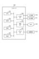
- the fault location estimating device 1 estimates the location of a fault in a common channel signaling network configured on an IP network. As shown in FIG. 3 , the failure location estimating device 1 includes a control unit 10 , an input/output unit 11 , and a storage unit 12 .
- the input/output unit 11 inputs and outputs information via the IP network 1000 between each device constituting the common channel signaling network 2000 on the IP network 1000.
- This input/output unit 11 is composed of a communication interface that transmits and receives information via the IP network 1000, and an input/output interface that inputs and outputs information between the device and an output device such as a monitor (not shown) that displays the estimated location of the fault.
- the storage unit 12 is composed of a hard disk, a flash memory, a RAM (Random Access Memory), or the like.
- IP address information 200 and link information 300 are stored in advance, and aggregated address information 400 is stored by an address aggregation unit 110 of the control unit, which will be described later.
- the IP address information 200 is information in which address information is associated with each device constituting an IP network including a common channel signaling network.
- the IP address information 200 stores address information that is preset for each device when the common channel signaling network is designed.
- the IP address information 200 stores IP addresses as address information for devices that make up the common channel signaling network.
- the IP address information 200 also stores network numbers of IP addresses as address information for network devices that make up the IP network.
- the network numbers can be written, for example, in Classless Inter-Domain Routing (CIDR) notation.
- the network numbers are addresses that indicate the network portion of the IP address used for routing (the host portion is all "0")
- the IP address information 200 stores, for devices that make up a common channel signaling network, a device name, a host name, and an IP address in association with each other, and for network devices that make up an IP network, stores, for each device name, a host name, and a network number expressed in CIDR notation in association with each other.
- the host name is "#a-1" and the IP address is "192.168.0.1”
- the host name is "#10-1" and the IP address is "172.16.10.1”
- the host name is "SW#1" and the network number is "192.168.0.0/24”.
- the link information 300 is information that associates address information at both ends of a link, which indicates the connection of the common link, with the common channel link for each device (host name) that constitutes the common channel signaling network.
- the link information 300 stores address information that is preset for the devices that constitute the common channel signaling network when the common channel signaling network is designed. Specifically, the link information 300 stores, for each device, a source address and a destination address of IP addresses indicating a connection for each common line link in association with each other.
- a preset link number, a source address, and a destination address are stored as common line links for each device in the link information 300.
- the link number is a number for identifying a common line link within the device.
- a common channel link with link number "1" of a certain device e.g., IP conversion device constituting the common channel signaling network indicates that the source address is "192.168.0.1" and the destination address is "172.16.10.1". The same applies to the other link numbers.
- the total address information 400 is information obtained by the address totaling unit 110 totaling, at a predetermined time interval, the number of IP addresses for which a signaling link fault alarm of a common line link has occurred (the number of alarm occurrences). For example, as shown in FIG. 6, the aggregated address information 400 stores an IP address at which a signaling link failure alarm has occurred and the number of alarms generated in association with each other. The example in FIG. 6 indicates that four alarms have occurred for the IP address "192.168.0.1.”
- the tally address information 400 is referred to by an estimation unit 120 of the control unit 10 (to be described later), whereby the location of the failure is estimated.
- the control unit 10 is responsible for all the processing executed by the fault location estimation device 1, and is composed of a fault address detection unit 100, an address aggregation unit 110, and an estimation unit 120.
- the fault address detection unit 100 collects logs generated by devices constituting the common channel signaling network 2000 from the IP network 1000 via the input/output unit 11, and detects the address of the common channel link where a fault has occurred from the signaling link fault alarm contained in the log.
- a plurality of fault address detectors 100A, 100B, 100C, and 100D are provided for each of the same types of devices constituting the common channel signaling network 2000.
- the faulty address detection unit 100A detects the address of the common line link in which a fault has occurred from the signaling link fault alarm generated by the IP conversion device 30.
- the fault address detection unit 100B detects the address of the common line link in which a fault has occurred from the signaling link fault alarm generated by the IP-STP 40.
- the faulty address detection unit 100C detects the address of the common line link in which a fault has occurred from a signaling link fault alarm generated by the SG 50.
- the faulty address detection unit 100D detects the address of the common line link in which a fault has occurred from a signaling link fault alarm generated by the SIP server 60.
- fault address detection unit 100 for each device of the same type that constitutes the common channel signaling network 2000, even if the format of the signaling link fault alarm differs for each device with different functions, the signaling link fault alarm can be analyzed in the same format, and address detection can be quickly processed.
- one fault address detection unit 100 may detect the addresses of common line links in which faults have occurred from all signaling link fault alarms.
- the faulty address detectors 100A, . . . , 100D have the same functions but differ in the signal link fault alarms they detect. Therefore, the internal configuration of the faulty address detector 100 will be described below by taking the faulty address detector 100A as an example.
- the fault address detection unit 100 includes a log collection unit 101 , a link fault extraction unit 102 , and an IP address conversion unit 103 .
- the log collection unit 101 collects logs generated by devices constituting the common channel signaling network 2000.
- the log collection unit 101 collects logs generated by the IP conversion device 30.
- the method of collecting the logs is not particularly limited.
- the log collection unit 101 may receive the logs when a device constituting the common channel signaling network 2000 outputs a log, or the log collection unit 101 may periodically inquire of the target device and collect the logs.
- the log collection unit 101 outputs the collected logs to the link failure extraction unit 102 .
- the link fault extraction unit 102 extracts, from the logs collected by the log collection unit 101, a signaling link fault alarm indicating a link fault in the common channel signaling system.
- the link fault extraction unit 102 extracts a signal link fault alarm from the log using a predetermined identifier. This signaling link fault alarm includes the time when the alarm occurred, the link number of the common line link, and the like.
- the link fault extraction unit 102 outputs the extracted signaling link fault alarm to the IP address conversion unit 103 together with the IP address of the device (such as the IP conversion device 30) that sent the signaling link fault alarm.
- the IP address conversion unit 103 refers to link information 300 in which the link numbers of the common line links are previously associated with the IP addresses of both ends of the common line links, and converts the link numbers of the common line links included in the signaling link fault alarms extracted by the link fault extraction unit 102 into the IP addresses of both ends of the common line links.
- the IP address conversion unit 103 refers to the IP address information 200, and identifies the device that has issued the signaling link fault alarm by the IP address of the device, using the host name, etc. Then, the IP address conversion unit 103 refers to the link information 300 (FIG. 5) corresponding to the identified device, and converts the link number into the source address and destination address corresponding to the link number.
- the IP address conversion unit 103 outputs the alarm occurrence time included in the signaling link failure alarm and the two converted IP addresses (the source address and the destination address) to the address compilation unit 110 .
- the address tallying unit 110 tallys up the IP addresses converted by the IP address conversion unit 103.
- the address tallying unit 110 tallys up the IP addresses at both ends of the common line link converted by the IP address conversion unit 103.
- the address counting unit 110 counts the IP addresses detected within a predetermined time period after any alarm is generated. Specifically, when the fault address detection unit 100 detects an IP address of a common line link in which a fault has occurred at any timing, the address tallying unit 110 tallyes the detected IP addresses within a predetermined time interval (X seconds) from the occurrence time of the given alarm, as shown in FIG. 7, and stores the tallying address information 400 in the memory unit 12.
- X seconds a predetermined time interval
- the start time of an arbitrary alarm "2022-11-11 06:00:00" is used, and the IP addresses (originating address and terminating address) detected in four alarms in a time period of X seconds are tallied.
- the predetermined time (X seconds) may be, for example, 2 seconds, which is specified as the response delay timer (T7) of the common line link.
- the address tallying unit 110 instructs the estimation unit 120 to perform an estimation operation at the timing when the IP addresses are tallied in a predetermined time period.
- the estimation unit 120 estimates the location of a failure based on the number of alarm occurrences (aggregated address information 400 ), which is the number of IP addresses aggregated by the address aggregation unit 110 .
- the estimation unit 120 estimates that the device corresponding to that IP address is the device in which a failure has occurred.
- the estimation unit 120 reads information (device name/host name) indicating the device corresponding to the uniquely identified IP address from the IP address information 200, and outputs it via the input/output unit 11 to an output device such as a monitor (not shown).
- the estimation unit 120 extracts the network numbers of IP addresses that have the same maximum alarm occurrence count and a common network section. The estimation unit 120 then reads information (device name/host name) indicating the network device of the IP network that corresponds to the extracted network number from the IP address information 200, and outputs this information via the input/output unit 11 to an output device such as a monitor (not shown).
- information device name/host name
- the estimation unit 120 estimates that the device corresponding to the IP address "192.168.0.1” described in the IP address information 200 (device name: IP conversion device, host name: #a-1) is the device in which a failure has occurred.
- the estimation unit 120 extracts the network number "192.168.0.0/24" of the common IP address. The estimation unit 120 then estimates that the device (device name: switch, host name: SW#1) corresponding to the network number "192.168.0.0/24" of the IP address described in IP address information 200 is the device where the failure occurred.
- the fault location estimation device 1 can estimate the fault location even when a single fault causes similar alarms to be generated simultaneously from multiple devices. Furthermore, the fault location estimation device 1 can estimate the fault location even when a fault occurs in a device that does not generate an alarm, such as a network device (silent fault).
- FIG. 9 is a sequence diagram showing the flow of the entire process executed by the failure point estimating device 1.
- the storage unit 12 has prestored therein IP address information 200 and link information 300 indicating the correspondence between the addresses of each device of the common channel signaling network configured on the IP network and the common channel links.
- Each device constituting the common channel signaling network 2000 (IP conversion device 30, IP-STP 40, etc.) generates and outputs a log periodically or irregularly (steps S1A, S1B, . . . ).
- the fault address detection unit 100 (100A, 100B, . . .) of the fault location estimating device 1 collects logs output in steps S1A, S1B, . . . and detects the address of the common line link in which a fault has occurred, by the following process.
- the log collection unit 101 of the faulty address detection unit 100A collects the logs generated in step S1A (step S10A). Note that in step S10A, the log collection unit 101 may sequentially collect the log output of the IP conversion device 30, or may periodically make inquiries to the IP conversion device 30 to collect the logs.
- the link fault extraction unit 102 of the fault address detection unit 100A extracts a signal link fault alarm including the time the alarm occurred, the link number of the common line link, etc. from the log collected in step S10A (step S11A).
- the IP address conversion unit 103 of the fault address detection unit 100A converts the link number included in the signaling link fault alarm extracted in step S11A into a corresponding IP address by referring to the link information 300 (step S12A). This identifies the IP addresses of the devices on both ends of the common line link where the fault has occurred.
- the faulty address detection unit 100B performs the same processes as steps S10A to S12A (steps S10B to S12B), except that the device that collects the logs is different.
- the faulty address detection units 100C and 100D also perform the same processes.
- the address tallying unit 110 of the failure location estimating device 1 tallys up the IP addresses converted in steps S12A, S12B, ... (step S13).
- the address tallying unit 110 stores the tallying result in the storage unit 12 as tally address information 400.
- the aggregated address information 400 aggregates IP addresses detected within a predetermined period of time, for example, two seconds, from the occurrence time of any given alarm.
- the estimation unit 120 of the failure point estimation device 1 estimates the failure point from the IP addresses (aggregated address information 400) collected in step S13 (step S14).
- the estimation unit 120 refers to the IP address information 200 and estimates that the device corresponding to that IP address is the device in which a failure has occurred.
- the failure location estimating device 1 can estimate the failure location even if a large number of alarms are generated.
- the estimation unit 120 refers to the IP address information 200 and estimates that the device corresponding to the network number of the IP address that has the same maximum value for the number of alarm occurrences and a common network section is the device where a failure has occurred. This allows the failure location estimating device 1 to estimate the failure location even in a device in the IP network 1000 that does not generate an alarm.
- Fig. 10 shows a part of the configuration of a common channel signaling network configured on an IP network.
- Fig. 10 shows an excerpt of Fig. 1 and Fig. 2 as a configuration necessary for explaining the estimation of a fault location.
- one network device (switch) 70 is illustrated in the IP network 1000
- two IP converters 30 are illustrated in the common channel signaling network 2000
- only four IP-STPs 40 are illustrated as having only one virtual machine VM41.
- the storage unit 12 of the failure location estimating device 1 stores IP address information 200 shown in FIG.
- the host name "#a-1” indicates that the IP conversion device 30 has an IP address of "192,168.0.1”.
- the host name "#10-1” indicates that the IP-STP 40 has an IP address of "172.16.10.1”.
- the host name "SW#1” indicates that the switch (network device 70) has an IP address network number of "192.168.0.0/24" in CIDR notation.
- the storage unit 12 of the failure location estimation device 1 stores link information 300A, 300B, 300C, and 300D for each device with host names "#a-1", "#a-2", “#10-1", and "#11-1” shown in Figures 12A to 12D. Host names "#20-1" and "#21-2" are not shown.
- the fault address detection unit 100 of the fault location estimation device 1 collects alarms from the IP conversion devices 30 with the host names "#a-1" and “#a-2” using the log collection unit 101, and extracts a signal link fault alarm using the link fault extraction unit 102. It is also assumed that the fault address detection unit 100 collects logs from the IP-STPs 40 with the host names "#10-1” and "#11-1” using the log collection unit 101, and extracts a signal link fault alarm using the link fault extraction unit 102.
- the fault address detection unit 100 uses the IP address conversion unit 103 to refer to the link information 300A in FIG. 12A and converts the link number to the IP address "1" of link number "1", "192.168.0.1”, “172.16.10.1".
- the fault address detection unit 100 uses the IP address conversion unit 103 to refer to link information 300B in FIG. 12B and converts the link number to the IP address "1" of link number "1", "192.168.0.2”, "172.16.11.1".
- the fault address detection unit 100 uses the IP address conversion unit 103 to refer to the link information 300C in FIG. 12C and converts the link number to the IP address "172.16.10.1” or "192.168.0.1” for link number "100".
- the fault address detection unit 100 uses the IP address conversion unit 103 to refer to link information 300D in FIG. 12D and converts the link number to the IP addresses "172.16.11.1” and "192.168.0.2" of link number "101".
- the address tallying unit 110 of the fault location estimation device 1 tallies the IP addresses identified by the link numbers of the signal link fault alarms in Figures 12A to 12D, and stores them in the storage unit 12 as the tallied address information 400 shown in Figure 13.
- the estimation unit 120 of the failure point estimation device 1 estimates the device that is the failure point from the aggregated address information 400 in FIG. 13, since there are multiple devices with the maximum alarm occurrence count of "2", the estimation unit 120 estimates that the device corresponding to the network number "192.168.0.0/24" of the IP address that has the same maximum alarm occurrence count and a common network part is the device in which a failure has occurred.
- the estimation unit 120 refers to the IP address information 200 in FIG. 11 and estimates that the device corresponding to the network number "192.168.0.0/24" is a switch (network device 70) with the host name "SW#1". In this manner, the fault location estimating device 1 can deduce that even a device that is not part of the common channel signaling network 2000 and does not generate an alarm is a faulty device.
- the failure location estimating device 1 is realized by a computer 900 having a configuration as shown in FIG. 14, for example.
- 14 is a hardware configuration diagram showing an example of a computer 900 that realizes the functions of the failure location estimation device 1 according to this embodiment.
- the computer 900 has a CPU 901, a ROM (Read Only Memory) 902, a RAM 903, a HDD (Hard Disk Drive) 904, an input/output I/F (Interface) 905, a communication I/F 906, and a media I/F 907.
- the CPU 901 operates based on a program (fault location estimation program) stored in the ROM 902 or HDD 904, and performs control by the control unit 10 (FIG. 3).
- the ROM 902 stores a boot program executed by the CPU 901 when the computer 900 is started, programs related to the hardware of the computer 900, etc.
- the CPU 901 controls an input device 910 such as a mouse or keyboard, and an output device 911 such as a display or printer, via an input/output I/F 905.
- the CPU 901 acquires data from the input device 910 via the input/output I/F 905, and outputs generated data to the output device 911.
- a GPU Graphics Processing Unit
- a processor may be used as a processor in addition to the CPU 901.
- the HDD 904 stores the programs executed by the CPU 901 and the data used by the programs.
- the communication I/F 906 receives data from other devices via a communication network (e.g., NW (Network) 920) and outputs the data to the CPU 901, and also transmits data generated by the CPU 901 to other devices via the communication network.
- NW Network
- the media I/F 907 reads the program (fault location estimation program) or data stored in the recording medium 912 and outputs it to the CPU 901 via the RAM 903.
- the CPU 901 loads the program related to the target processing from the recording medium 912 onto the RAM 903 via the media I/F 907, and executes the loaded program.
- the recording medium 912 is an optical recording medium such as a DVD (Digital Versatile Disc) or a PD (Phase change rewritable Disk), a magneto-optical recording medium such as an MO (Magneto Optical Disk), a magnetic recording medium, a semiconductor memory, etc.
- CPU 901 of computer 900 executes a program loaded onto RAM 903 to realize the function of the fault location estimation program.
- Data in RAM 903 is also stored in HDD 904.
- CPU 901 reads and executes a program related to a target process from recording medium 912. Additionally, CPU 901 may read a program related to a target process from another device via a communication network (NW 920).
- NW 920 a communication network
- the fault location estimation device 1 is a fault location estimation device for estimating a fault location in a common channel signaling network 2000 configured on an IP network 1000, and is characterized by comprising: a log collection unit 101 for collecting logs from devices on the common channel signaling network 2000; a link fault extraction unit 102 for extracting a signaling link fault alarm indicating a link fault of the common channel signaling system from the log; an IP address conversion unit 103 for converting the link number of the common channel link included in the signaling link fault alarm into the IP addresses of both ends of the common channel link by referring to link information in which the link numbers of the common channel links are previously associated with the IP addresses of both ends of the common channel link; an address counting unit 110 for counting the IP addresses converted by the IP address conversion unit 103; and an estimation unit 120 for estimating the fault location based on the number of alarm occurrences, which is the number of IP addresses counted by the
- the fault location estimation device 1 can quickly isolate and estimate the fault location based on the number of IP addresses corresponding to the link numbers contained in the alarms (number of alarms generated).
- the signal link fault alarm includes the time of occurrence of the alarm
- the address counting unit 110 counts the IP addresses converted by the IP address conversion unit 103 within a predetermined time interval from the time of occurrence of the signal link fault alarm
- the estimation unit 120 estimates the fault location based on the number of alarm occurrences, which is the number of IP addresses counted within the time interval.
- the fault location estimation device 1 aggregates IP addresses within a predetermined time period after any signal link fault alarm occurs, thereby increasing the possibility of estimating a single fault location.
- the estimation unit 120 estimates the device corresponding to that IP address as the fault location, and when an IP address is not uniquely identified by the maximum number of alarm occurrences, it estimates the network device of the IP network corresponding to the network number of the IP address that has the same maximum number of alarm occurrences and a common network part as the fault location.
- the fault location estimation device 1 can estimate, as the fault location, the equipment of the common channel signaling network corresponding to the IP address with the highest number of alarms. Furthermore, when there are multiple IP addresses with the highest number of alarms, the fault location estimation device 1 can estimate the fault location by the network number. This allows the fault location estimation device 1 to estimate, as the fault location, even network equipment of an IP network that does not generate alarms.
- Fault location estimation device 10
- Control unit 100
- Fault address detection unit 101
- Log collection unit 102
- Link fault extraction unit 103
- IP address conversion unit 110
- Address collection unit 120
- Estimation unit 11
- Input/output unit 12
- Storage unit 200
- IP address information 300
- Aggregated address information 1000
- IP network 2000
- Common channel signaling network 3000 Fault location estimation system
Landscapes
- Engineering & Computer Science (AREA)
- Computer Networks & Wireless Communication (AREA)
- Signal Processing (AREA)
- Data Exchanges In Wide-Area Networks (AREA)
Abstract
Description
IP網上で共通線信号網を構成する場合、共通線信号網を構成する装置(IP変換装置、IP-STP〔Signal Transfer Point〕、SG〔Signaling Gateway〕等)、共通線信号をIP網上で転送するスイッチ、ルータ等のネットワーク機器(転送機器)等、構成が複雑化している。
また、共通線信号網のIP化および仮想化により、単一のハードウェア障害であっても、複数のリンク障害が生じやすくなり、大量のアラームが発生する。
例えば、仮想プライベートネットワーク(VPN)において、ユーザから故障申告のあった複数の疎通経路から、重複数の多いネットワーク構成ノードを故障被疑箇所として特定する手法が開示されている(特許文献1参照)。
また、非特許文献2に記載の手法は、if-thenルールに基づいて、特異な障害パターンから故障箇所を推定するため、共通線信号網のように、1箇所の障害によって、複数の装置から同時に同様のアラームが発生する場合、故障箇所を推定することは困難である。
図1は、IP網1000上に共通線信号網2000を構成し、さらに、本実施形態に係る故障箇所推定装置1をIP網1000に接続して構成した故障箇所推定システム3000の全体構成を示す図である。
共通線信号網2000は、共通線信号方式のPSTN(公衆交換電話網)である。
IP網1000上で構成される共通線信号網2000は、メタル収容装置20、IP変換装置30、IP-STP40、SG50、SIPサーバ60等で構成される。なお、これらの装置は、共通線信号網2000内に複数接続される。
IP変換装置30は、メタル収容装置20の固定電話の信号をIPパケットの共通線信号に変換するものである。これによって、メタル収容装置20は、IP網1000にデータを送出することができる。
SG(Signaling Gateway)50は、共通線信号をIP-STP40に転送するゲートウェイである。
SIP(Session Initiation Protocol)サーバ60は、IP網1000上で音声通話を利用する際、発着信や応答などの呼制御を行うサーバであって、例えば、電話番号とIPアドレスとを紐付ける機能を有する。
なお、IP-STP40、SG50、SIPサーバ60は、可用性確保のため、それぞれ、複数の仮想マシンVM41,…,41、VM51,…,51、VM61,…,61を実装している場合がある。
IP網1000および共通線信号網2000を構成する装置は、公知の装置であるため、これ以上の詳細な説明は省略する。
次に、本実施形態に係る故障箇所推定装置1の構成について説明する。
故障箇所推定装置1は、IP網上に構成した共通線信号網における故障箇所を推定するものである。
図3に示すように、故障箇所推定装置1は、制御部10と、入出力部11と、記憶部12とを備える。
この記憶部12には、IPアドレス情報200およびリンク情報300が予め格納され、後記する制御部のアドレス集計部110によって、集計アドレス情報400が格納される。
IPアドレス情報200には、共通線信号網を構成する装置については、アドレス情報としてIPアドレスを対応付けて格納しておく。また、IPアドレス情報200には、IP網を構成するネットワーク機器については、アドレス情報としてIPアドレスのネットワーク番号を対応付けて格納しておく。ネットワーク番号は、例えば、CIDR(Classless Inter-Domain Routing)表記により記述することができる。ネットワーク番号は、ルーティングに用いるIPアドレスのネットワーク部を示すアドレス(ホスト部がすべて“0”)である。
図4の例では、あるIP変換装置30(図1)については、ホスト名が「#a-1」、IPアドレスが「192.168.0.1」であり、あるIP-STP40(図1)については、ホスト名が「#10-1」、IPアドレスが「172.16.10.1」であることを示している。また、あるネットワーク機器(スイッチ)70(図1)については、ホスト名が「SW#1」で、ネットワーク番号が「192.168.0.0/24」であることを示している。
具体的には、リンク情報300には、装置ごとに共通線リンクごとの接続を示すIPアドレスの発アドレスと着アドレスとを対応付けて格納しておく。
図5の例では、共通線信号網を構成するある装置(例えば、IP変換装置)のリンク番号が「1」の共通線リンクは、発アドレスが「192.168.0.1」、着アドレスが「172.16.10.1」であることを示している。他のリンク番号についても同様である。
例えば、集計アドレス情報400には、図6に示すように、信号リンク障害アラームが発生したIPアドレスとアラーム発生数とを対応付けて格納する。
図6の例では、IPアドレス「192.168.0.1」に対して、アラームが4件発生したことを示している。
この集計アドレス情報400を、後記する制御部10の推定部120が参照することで、故障箇所が推定されることになる。
ここでは、共通線信号網2000を構成する同種の装置ごとに、複数の障害アドレス検出部100A,100B,100C,100Dを備える。
障害アドレス検出部100Bは、IP-STP40が発生する信号リンク障害アラームから障害が発生した共通線リンクのアドレスを検出するものである。
障害アドレス検出部100Cは、SG50が発生する信号リンク障害アラームから障害が発生した共通線リンクのアドレスを検出するものである。
障害アドレス検出部100Dは、SIPサーバ60が発生する信号リンク障害アラームから障害が発生した共通線リンクのアドレスを検出するものである。
もちろん、1つの障害アドレス検出部100ですべての信号リンク障害アラームから障害が発生した共通線リンクのアドレスを検出することとしてもよい。
障害アドレス検出部100は、ログ収集部101と、リンク障害抽出部102と、IPアドレス変換部103とを含んで構成される。
なお、ログの収集方法は、特に限定するものではなく、例えば、共通線信号網2000を構成する装置がログを出力したタイミングで、ログ収集部101がログを受信することとしてもよいし、ログ収集部101が定期的に対象装置に問い合わせを行ってログを収集することとしてもよい。
ログ収集部101は、収集したログをリンク障害抽出部102に出力する。
リンク障害抽出部102は、予め定めた識別子により、ログから信号リンク障害アラームを抽出する。
この信号リンク障害アラームには、アラームが発生した時刻、共通線リンクのリンク番号等が含まれている。
リンク障害抽出部102は、抽出した信号リンク障害アラームを、信号リンク障害アラームを送出した装置(IP変換装置30等)のIPアドレスとともに、IPアドレス変換部103に出力する。
ここでは、IPアドレス変換部103は、IPアドレス情報200を参照し、信号リンク障害アラームを送出した装置のIPアドレスにより、アラームを発生した装置をホスト名等で特定する。そして、IPアドレス変換部103は、特定した装置に対応するリンク情報300(図5)を参照し、リンク番号を、リンク番号に対応する発アドレスおよび着アドレスに変換する。
これによって、障害アドレス検出部100は、障害が発生した共通線リンクの両端の装置のIPアドレスを検出することができる。
IPアドレス変換部103は、信号リンク障害アラームに含まれるアラームの発生時刻と、変換した2つのIPアドレス(発アドレスおよび着アドレス)とを、アドレス集計部110に出力する。
具体的には、アドレス集計部110は、障害アドレス検出部100で任意のタイミングで障害が発生した共通線リンクのIPアドレスが検出された場合、図7に示すように、任意のアラームの発生時刻から、予め定めた時間区間(X秒)内で検出したIPアドレスを集計し、集計アドレス情報400として、記憶部12に格納する。
同様に、IPアドレス「192.168.0.2」、「172.16.10.1」、「172.16.11.1」の各装置に対応するアラームがX秒内で2つ発生している。
なお、予め定めた時間(X秒)は、例えば、共通線リンクの応答遅延タイマ(T7)として規定されている2秒を用いることができる。
アドレス集計部110は、予め定めた時間区間でIPアドレスを集計したタイミングで、推定部120に推定動作を指示する。
推定部120は、集計アドレス情報400において、アラーム発生数の最大値で一意にIPアドレスが特定される場合、当該IPアドレスに対応する装置を故障が発生した装置として推定する。ここでは、推定部120は、一意に特定されたIPアドレスに対応する装置を示す情報(装置名/ホスト名)を、IPアドレス情報200から読み出して、入出力部11を介して、図示を省略したモニタ等の出力装置に出力する。
集計アドレス情報400Aのように、アラーム発生数の最大値“4”で一意にIPアドレス「192.168.0.1」が特定される場合、推定部120は、IPアドレス情報200に記述されているIPアドレス「192.168.0.1」に対応する装置(装置名:IP変換装置、ホスト名:#a-1)を、故障が発生した装置として推定する。
次に、本実施形態に係る故障箇所推定装置1が実行する処理について説明する。
図9は、故障箇所推定装置1が実行する全体の処理の流れを示すシーケンス図である。構成については、適宜図1,図3を参照することとする。
なお、記憶部12には、IP網上に構成された共通線信号網の各装置のアドレスや共通線リンクの対応を示すIPアドレス情報200、リンク情報300が予め格納されているものとする。
故障箇所推定装置1の障害アドレス検出部100(100A,100B,…)は、以下の処理により、ステップS1A,S1B,…で出力されるログを収集し、障害が発生した共通線リンクのアドレスを検出する。
同様に、障害アドレス検出部100Bにおいても、ログを収集する装置が異なるだけで、ステップS10A~S12Aと同様に処理を行う(ステップS10B~S12B)。図示を省略するが、障害アドレス検出部100C,100Dにおいても同様である。
なお、ステップS13において、集計アドレス情報400は、任意のアラームの発生時刻から、予め定めた時間、例えば2秒の間で検出したIPアドレスを集計する。
このステップS14において、推定部120は、アラーム発生数の最大値で一意にIPアドレスが特定される場合、IPアドレス情報200を参照して、当該IPアドレスに対応する装置を故障が発生した装置として推定する。
これによって、故障箇所推定装置1は、共通線信号網2000を構成する装置で故障が発生した場合、大量にアラームが発生しても、故障箇所を推定することができる。
これによって、故障箇所推定装置1は、IP網1000において、アラームを発生しない装置であっても、故障箇所を推定することができる。
次に、故障箇所推定装置1が故障箇所を推定する処理の一例を具体的に説明する。
図10は、IP網上に構成した共通線信号網の構成の一部を示す。図10は、故障箇所の推定を説明するために必要な構成として、図1,図2の一部を抜粋したものである。
図10では、IP網1000にネットワーク機器(スイッチ)70を1台、共通線信号網2000にIP変換装置30を2台、IP-STP40を4台だけ図示している。また、それぞれのIP-STP40は、1つの仮想マシンVM41だけを図示している。
この構成において、故障箇所推定装置1の記憶部12には、図11に示すIPアドレス情報200が格納されているものとする。
図13の例では、アラーム発生数の最大値“2”が複数存在するため、推定部120は、アラーム発生数の最大値が同じでネットワーク部が共通するIPアドレスのネットワーク番号「192.168.0.0/24」に対応する装置を、故障が発生した装置として推定する。この場合、推定部120は、図11のIPアドレス情報200を参照して、ネットワーク番号「192.168.0.0/24」に対応する装置が、ホスト名「SW#1」のスイッチ(ネットワーク機器70)であると推定する。
このように、故障箇所推定装置1は、共通線信号網2000の構成ではない、アラームを発生しない装置であっても故障装置として推定することができる。
本実施形態に係る故障箇所推定装置1は、例えば図14で示すような構成のコンピュータ900によって実現される。
図14は、本実施形態に係る故障箇所推定装置1の機能を実現するコンピュータ900の一例を示すハードウェア構成図である。コンピュータ900は、CPU901、ROM(Read Only Memory)902、RAM903、HDD(Hard Disk Drive)904、入出力I/F(Interface)905、通信I/F906およびメディアI/F907を有する。
以下、本発明に係る故障箇所推定装置の効果について説明する。
本発明に係る故障箇所推定は、IP網1000上に構成した共通線信号網2000における故障箇所を推定する故障箇所推定装置1であって、共通線信号網2000上の装置からログを収集するログ収集部101と、ログから共通線信号方式のリンク障害を示す信号リンク障害アラームを抽出するリンク障害抽出部102と、共通線リンクのリンク番号と共通線リンクの両端のIPアドレスとを予め対応付けたリンク情報を参照し、信号リンク障害アラームに含まれる共通線リンクのリンク番号を共通線リンクの両端のIPアドレスに変換するIPアドレス変換部103と、IPアドレス変換部103で変換されたIPアドレスを集計するアドレス集計部110と、アドレス集計部110で集計されたIPアドレスの数であるアラーム発生数によって、故障箇所を推定する推定部120と、を備えることを特徴とする。
10 制御部
100 障害アドレス検出部
101 ログ収集部
102 リンク障害抽出部
103 IPアドレス変換部
110 アドレス収集部
120 推定部
11 入出力部
12 記憶部
200 IPアドレス情報
300 リンク情報
400 集計アドレス情報
1000 IP網
2000 共通線信号網
3000 故障箇所推定システム
Claims (5)
- IP網上に構成した共通線信号網における故障箇所を推定する故障箇所推定装置であって、
前記共通線信号網上の装置からログを収集するログ収集部と、
前記ログから共通線信号方式のリンク障害を示す信号リンク障害アラームを抽出するリンク障害抽出部と、
共通線リンクのリンク番号と前記共通線リンクの両端のIPアドレスとを予め対応付けたリンク情報を参照し、前記信号リンク障害アラームに含まれる共通線リンクのリンク番号を前記共通線リンクの両端のIPアドレスに変換するIPアドレス変換部と、
前記IPアドレス変換部で変換されたIPアドレスを集計するアドレス集計部と、
前記アドレス集計部で集計されたIPアドレスの数であるアラーム発生数によって、前記故障箇所を推定する推定部と、
を備えることを特徴とする故障箇所推定装置。 - 前記信号リンク障害アラームにはアラームの発生時刻が含まれており、
前記アドレス集計部は、前記信号リンク障害アラームの発生時刻から予め定めた時間区間内で、前記IPアドレス変換部で変換されたIPアドレスを集計し、
前記推定部は、前記時間区間内で集計されたIPアドレスの数であるアラーム発生数によって、前記故障箇所を推定すること
を特徴とする請求項1に記載の故障箇所推定装置。 - 前記推定部は、前記アラーム発生数の最大値で一意にIPアドレスが特定される場合、当該IPアドレスに対応する装置を故障箇所と推定し、
前記アラーム発生数の最大値で一意にIPアドレスが特定されない場合、前記アラーム発生数の最大値が同じでネットワーク部が共通するIPアドレスのネットワーク番号に対応する前記IP網のネットワーク機器を故障箇所と推定すること
を特徴とする請求項1または請求項2に記載の故障箇所推定装置。 - IP網上に構成した共通線信号網における故障箇所を推定する故障箇所推定装置の故障箇所推定方法であって、
前記故障箇所推定装置は、
前記共通線信号網上の装置からログを収集するステップと、
前記ログから共通線信号方式のリンク障害を示す信号リンク障害アラームを抽出するステップと、
共通線リンクのリンク番号と前記共通線リンクの両端のIPアドレスとを予め対応付けたリンク情報を参照し、前記信号リンク障害アラームに含まれる共通線リンクのリンク番号を前記共通線リンクの両端のIPアドレスに変換するステップと、
前記変換されたIPアドレスを集計するステップと、
前記集計されたIPアドレスの数であるアラーム発生数によって、前記故障箇所を推定するステップと、
を実行することを特徴とする故障箇所推定方法。 - IP網上に構成した共通線信号網における故障箇所を推定する故障箇所推定装置としてのコンピュータに、
前記共通線信号網上の装置からログを収集する手順、
前記ログから共通線信号方式のリンク障害を示す信号リンク障害アラームを抽出する手順、
共通線リンクのリンク番号と前記共通線リンクの両端のIPアドレスとを予め対応付けたリンク情報を参照し、前記信号リンク障害アラームに含まれる共通線リンクのリンク番号を前記共通線リンクの両端のIPアドレスに変換する手順、
前記変換されたIPアドレスを集計する手順、
前記集計されたIPアドレスの数であるアラーム発生数によって、前記故障箇所を推定する手順、
を実行させるための故障箇所推定プログラム。
Priority Applications (2)
| Application Number | Priority Date | Filing Date | Title |
|---|---|---|---|
| PCT/JP2023/004677 WO2024171237A1 (ja) | 2023-02-13 | 2023-02-13 | 故障箇所推定装置、故障箇所推定方法および故障箇所推定プログラム |
| JP2025500419A JPWO2024171237A1 (ja) | 2023-02-13 | 2023-02-13 |
Applications Claiming Priority (1)
| Application Number | Priority Date | Filing Date | Title |
|---|---|---|---|
| PCT/JP2023/004677 WO2024171237A1 (ja) | 2023-02-13 | 2023-02-13 | 故障箇所推定装置、故障箇所推定方法および故障箇所推定プログラム |
Publications (1)
| Publication Number | Publication Date |
|---|---|
| WO2024171237A1 true WO2024171237A1 (ja) | 2024-08-22 |
Family
ID=92420891
Family Applications (1)
| Application Number | Title | Priority Date | Filing Date |
|---|---|---|---|
| PCT/JP2023/004677 Ceased WO2024171237A1 (ja) | 2023-02-13 | 2023-02-13 | 故障箇所推定装置、故障箇所推定方法および故障箇所推定プログラム |
Country Status (2)
| Country | Link |
|---|---|
| JP (1) | JPWO2024171237A1 (ja) |
| WO (1) | WO2024171237A1 (ja) |
Citations (4)
| Publication number | Priority date | Publication date | Assignee | Title |
|---|---|---|---|---|
| JPH11238036A (ja) * | 1998-02-19 | 1999-08-31 | Nec Corp | 分散処理障害ログ自動管理システム |
| JP2009159513A (ja) * | 2007-12-27 | 2009-07-16 | Nec Corp | ネットワークシステム、ゲートウェイ装置、データ通信方法及びプログラム |
| JP2010062777A (ja) * | 2008-09-03 | 2010-03-18 | Nec Corp | Sctpアソシエーション集約装置、その装置を含む通信システムおよびルーティング方法 |
| JP2011171981A (ja) * | 2010-02-18 | 2011-09-01 | Oki Electric Industry Co Ltd | ネットワーク障害検出システム |
-
2023
- 2023-02-13 WO PCT/JP2023/004677 patent/WO2024171237A1/ja not_active Ceased
- 2023-02-13 JP JP2025500419A patent/JPWO2024171237A1/ja active Pending
Patent Citations (4)
| Publication number | Priority date | Publication date | Assignee | Title |
|---|---|---|---|---|
| JPH11238036A (ja) * | 1998-02-19 | 1999-08-31 | Nec Corp | 分散処理障害ログ自動管理システム |
| JP2009159513A (ja) * | 2007-12-27 | 2009-07-16 | Nec Corp | ネットワークシステム、ゲートウェイ装置、データ通信方法及びプログラム |
| JP2010062777A (ja) * | 2008-09-03 | 2010-03-18 | Nec Corp | Sctpアソシエーション集約装置、その装置を含む通信システムおよびルーティング方法 |
| JP2011171981A (ja) * | 2010-02-18 | 2011-09-01 | Oki Electric Industry Co Ltd | ネットワーク障害検出システム |
Also Published As
| Publication number | Publication date |
|---|---|
| JPWO2024171237A1 (ja) | 2024-08-22 |
Similar Documents
| Publication | Publication Date | Title |
|---|---|---|
| JP4371905B2 (ja) | 不正アクセス検知装置、不正アクセス検知方法、不正アクセス検知プログラムおよび分散型サービス不能化攻撃検知装置 | |
| US7266758B2 (en) | Network monitoring program, network monitoring method, and network monitoring apparatus | |
| CN104798341B (zh) | 在电子网络上表征服务水平 | |
| US6519228B1 (en) | System and method of operation for verifying and validating public switch telephone networks (PSTN) to (IP) network services | |
| CN101366236B (zh) | 用于识别通信网络中的故障的方法和系统 | |
| CN111030873A (zh) | 一种故障诊断方法及装置 | |
| WO2020240680A1 (ja) | 障害推定支援装置、障害推定支援方法、および、障害推定支援プログラム | |
| CN101702712B (zh) | 一种探测技术与语音呼叫备份联动方法及装置 | |
| US10742485B2 (en) | Method for determining a sequence of events, a determination device for determining a sequence of events, and a providing device | |
| JP2012038213A (ja) | 判定装置、判定方法及びコンピュータプログラム | |
| US8195977B2 (en) | Network fault isolation | |
| US8009585B2 (en) | Method and system for topology discovery in an SIP network | |
| EP3756310B1 (en) | Method and first node for managing transmission of probe messages | |
| Wallschläger et al. | Automated anomaly detection in virtualized services using deep packet inspection | |
| US12143286B2 (en) | Network monitoring device, network monitoring method, and network monitoring program | |
| CN112636944A (zh) | Olt设备脱网智能诊断方法及系统 | |
| JP4391960B2 (ja) | リソース管理装置、システムおよび方法 | |
| US7797420B1 (en) | Method and apparatus for representing, managing and problem reporting in VoIP networks | |
| US12445359B1 (en) | System and method for unified communication monitoring | |
| CN117014914A (zh) | 网络故障的定位方法及装置 | |
| CN121771333B (zh) | 一种基于电话交互的信令转换方法以及系统 | |
| US20250240255A1 (en) | Predictive or preemptive machine learning (ml) -driven optimization of internet protocol (ip) -based communications service | |
| JP2007274282A (ja) | ネットワーク監視プログラム、ネットワーク監視方法、およびネットワーク監視装置 | |
| CN116319260B (zh) | 一种网络故障诊断方法、装置、设备及存储介质 | |
| CN119299361B (zh) | 一种bgp异常路由识别方法、装置、设备及介质 |
Legal Events
| Date | Code | Title | Description |
|---|---|---|---|
| 121 | Ep: the epo has been informed by wipo that ep was designated in this application |
Ref document number: 23922578 Country of ref document: EP Kind code of ref document: A1 |
|
| ENP | Entry into the national phase |
Ref document number: 2025500419 Country of ref document: JP Kind code of ref document: A |
|
| WWE | Wipo information: entry into national phase |
Ref document number: 2025500419 Country of ref document: JP |
|
| NENP | Non-entry into the national phase |
Ref country code: DE |
|
| 122 | Ep: pct application non-entry in european phase |
Ref document number: 23922578 Country of ref document: EP Kind code of ref document: A1 |