WO2024166759A1 - シミュレーション装置、シミュレーション方法及びプログラム - Google Patents
シミュレーション装置、シミュレーション方法及びプログラム Download PDFInfo
- Publication number
- WO2024166759A1 WO2024166759A1 PCT/JP2024/003003 JP2024003003W WO2024166759A1 WO 2024166759 A1 WO2024166759 A1 WO 2024166759A1 JP 2024003003 W JP2024003003 W JP 2024003003W WO 2024166759 A1 WO2024166759 A1 WO 2024166759A1
- Authority
- WO
- WIPO (PCT)
- Prior art keywords
- simulation device
- relaxation function
- series data
- time series
- dielectric relaxation
- Prior art date
- Legal status (The legal status is an assumption and is not a legal conclusion. Google has not performed a legal analysis and makes no representation as to the accuracy of the status listed.)
- Ceased
Links
Images





Classifications
-
- G—PHYSICS
- G16—INFORMATION AND COMMUNICATION TECHNOLOGY [ICT] SPECIALLY ADAPTED FOR SPECIFIC APPLICATION FIELDS
- G16C—COMPUTATIONAL CHEMISTRY; CHEMOINFORMATICS; COMPUTATIONAL MATERIALS SCIENCE
- G16C10/00—Computational theoretical chemistry, i.e. ICT specially adapted for theoretical aspects of quantum chemistry, molecular mechanics, molecular dynamics or the like
Definitions
- This disclosure relates to a simulation device, a simulation method, and a program.
- Patent Document 1 discloses a material design system that predicts various physical properties of polymeric materials by computer simulation.
- Non-Patent Document 1 discloses a technique for calculating the dielectric constant and loss from the dipole moment of a polyethylene system containing additives using molecular dynamics simulation.
- Non-Patent Document 2 discloses a technique for calculating the dielectric loss from the total dipole moment of a polyethylene copolymer using molecular dynamics simulation.
- This disclosure provides an accurate method for deriving the dielectric relaxation function of a material.
- the simulation device is a simulation device having a control unit, which calculates time series data of the dipole moment of a target substance and outputs a dielectric relaxation function based on the time series data in a specified frequency band.
- the dielectric relaxation function of a substance can be derived with high accuracy.
- a second aspect of the present disclosure is a simulation device according to the first aspect, in which the control unit extracts the time series data of the frequency band using a high-pass filter.
- a third aspect of the present disclosure is a simulation device according to the second aspect, in which the control unit determines the cutoff frequency of the high-pass filter based on the length of the dielectric relaxation function.
- a fourth aspect of the present disclosure is a simulation device according to the first aspect, in which the control unit calculates the time series data of the dipole moment by molecular dynamics calculation.
- a fifth aspect of the present disclosure is a simulation device according to any one of the first to fourth aspects, in which the control unit frequency-resolves the dielectric relaxation function.
- a sixth aspect of the present disclosure is a simulation device according to the fifth aspect, in which the control unit outputs the complex dielectric constant, the dielectric tangent, the complex electrical conductivity, or the resistivity for each frequency.
- a control unit of a simulation device executes the steps of calculating time series data of the dipole moment of a target substance and outputting a dielectric relaxation function based on the time series data in a specified frequency band.
- the program according to the eighth aspect of the present disclosure causes a control unit of a simulation device to execute a procedure for calculating time series data of the dipole moment of a target substance, and a procedure for outputting a dielectric relaxation function based on the time series data in a specified frequency band.
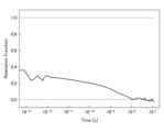
- FIG. 1 is a diagram showing a first example of a dielectric relaxation function according to the prior art.
- FIG. 2 is a diagram showing a second example of a dielectric relaxation function according to the prior art.
- FIG. 3 is a diagram showing a third example of a dielectric relaxation function according to the prior art.
- FIG. 4 is a diagram showing a fourth example of a dielectric relaxation function according to the prior art.
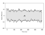
- FIG. 5 is a diagram showing an example of a dipole moment before filtering.
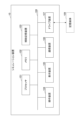
- FIG. 6 is a block diagram showing an example of a hardware configuration of the simulation apparatus.
- FIG. 7 is a flowchart showing an example of a processing procedure of the simulation method.
- FIG. 8 is a diagram showing an example of a dipole moment after filtering.
- FIG. 1 is a diagram showing a first example of a dielectric relaxation function according to the prior art.
- FIG. 2 is a diagram showing a second example of a dielectric relaxation function according to the prior art.
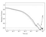
- FIG. 9 is a diagram showing a first example of a dielectric relaxation function according to an embodiment.
- FIG. 10 is a diagram illustrating a second example of a dielectric relaxation function according to the embodiment.
- FIG. 11 is a diagram illustrating an example of a complex dielectric constant according to the embodiment.
- FIG. 12 is a diagram illustrating an example of a dielectric tangent according to the embodiment.
- One embodiment of the present disclosure is a simulation device that calculates the physical properties of a polymer by molecular dynamics calculation or the like.
- the simulation device in this embodiment derives a dielectric relaxation function of a polymer to be calculated (hereinafter, also referred to as a "target substance"), and calculates the physical properties of the target substance based on the dielectric relaxation function.
- Examples of physical properties that can be calculated based on the dielectric relaxation function include electrical properties such as frequency-dependent complex dielectric constant, dielectric loss tangent, complex electrical conductivity, and resistivity.
- the physical properties of a target substance are calculated as follows.
- time series data M(t) of the dipole moment is calculated using molecular dynamics calculations, where t represents time.
- the dielectric relaxation function ⁇ (t) is calculated from the time series data M(t) of the dipole moment.
- the dielectric relaxation function ⁇ (t) can be calculated using formula (1).
- Figs. 1 to 4 are diagrams showing first to fourth examples of dielectric relaxation functions according to the conventional technology.
- the first example of the dielectric relaxation function is an example of a correctly derived dielectric relaxation function.
- the second to fourth examples of the dielectric relaxation function are examples of an incorrectly derived dielectric relaxation function.
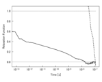
- the dielectric relaxation functions shown in Figures 2 to 4 have shapes that decay to near 0 and then begin to rise (see Figure 2), drop sharply from a value of 1 or more to a value below 0 (see Figure 3), or decay to a value below 0 and then rise (Figure 4). Therefore, the dielectric relaxation functions shown in Figures 2 to 4 have not been derived correctly.
- Figure 5 shows time series data of dipole moments calculated by molecular dynamics calculations, and is the result of equilibration calculations with a time step size of 1 femtosecond and a time length of 500 nanoseconds.
- Figure 5 shows the time changes of the dipole moments in the x-axis, y-axis, and z-axis directions in the simulation space.
- the dipole moments in each axial direction are shown overlapping.
- the dipole moments in the x-axis and y-axis directions are actually distributed in a range centered around 0, just like the dipole moment in the z-axis direction.
- Equation (1) assumes that the average value of the dipole moment is constant over any time domain. However, the time series data of the dipole moment shown in Figure 5 shows a gradual decrease in the time axis, as indicated by the dashed arrow. Therefore, the time series data of the dipole moment derived by molecular dynamics calculations does not satisfy the assumptions of equation (1).
- the dipole moment calculation system is small-scale compared to actual materials and is susceptible to local influences. As a result, the dipole moment shifts with structural relaxation, and this effect is thought to appear in the low-frequency region. Therefore, if the low-frequency components are removed from the time-series data of the dipole moment, it is possible to suppress the gradual fluctuations shown in Figure 5.
- the purpose of this embodiment is to accurately derive the dielectric relaxation function of a target substance. If a highly accurate dielectric relaxation function can be derived, the accuracy of the physical property values calculated using that dielectric relaxation function will also improve.
- Fig. 6 is a block diagram showing an example of a hardware configuration of the simulation device 10 in this embodiment.
- the simulation device 10 has a processor 101, a memory 102, an auxiliary storage device 103, an operation device 104, a display device 105, a communication device 106, and a drive device 107.
- the hardware components of the simulation device 10 are connected to each other via a bus 108.
- the processor 101 has various computing devices such as a CPU (Central Processing Unit).
- the processor 101 reads various programs installed in the auxiliary storage device 103 onto the memory 102 and executes them.
- Memory 102 has a primary storage device such as ROM (Read Only Memory) and RAM (Random Access Memory).
- the processor 101 and memory 102 form what is known as a computer (hereinafter also referred to as the "control unit"), and the processor 101 executes various programs read onto memory 102, causing the computer to realize various functions.
- the auxiliary storage device 103 (hereinafter also referred to as the “storage unit”) stores various programs and various data used when the various programs are executed by the processor 101.
- the operation device 104 is an operation device that allows the user of the simulation device 10 to perform various operations.
- the display device 105 is a display device that displays the results of various processes executed by the simulation device 10.
- the communication device 106 is a communication device for communicating with external devices via a network (not shown).
- the drive unit 107 is a device for setting the storage medium 109.
- the storage medium 109 referred to here includes media that store information optically, electrically, or magnetically, such as CD-ROMs, flexible disks, and magneto-optical disks.
- the storage medium 109 may also include semiconductor memory that stores information electrically, such as ROM and flash memory.
- the various programs to be installed in the auxiliary storage device 103 are installed, for example, by setting the distributed storage medium 109 in the drive device 107 and reading out the various programs stored in the storage medium 109 by the drive device 107.
- the various programs to be installed in the auxiliary storage device 103 may be installed by downloading them from a network via the communication device 106.
- FIG. 7 is a flowchart showing an example of the flow of a simulation method executed by the simulation device 10 in this embodiment.
- step S1 the control unit of the simulation device 10 accepts input of calculation conditions.
- the calculation conditions include identification information that identifies the target substance and information that indicates the length of the dielectric relaxation function.
- the identification information may be any information that can identify a substance. Examples of information that can identify a substance include compound names, structural formulas, SMILES (Simplified Molecular Input Line Entry System) information, etc.
- the length of the dielectric relaxation function is the length of the time axis of the dielectric relaxation function. In this embodiment, the length of the dielectric relaxation function is 100 nanoseconds.
- step S2 the control unit of the simulation device 10 calculates the dipole moment of the target substance at a predetermined time interval by molecular dynamics calculation. This generates time series data of the dipole moment.
- the time length for calculating the dipole moment may be long enough to derive the dielectric relaxation function.
- the time length for calculating the dipole moment is 500 nanoseconds.
- step S3 the control unit of the simulation device 10 designs a high-pass filter based on the calculation conditions received in step S1.
- the cutoff frequency of the high-pass filter is the inverse of the length of the dielectric relaxation function.
- the length of the dielectric relaxation function is set to 100 nanoseconds, so the cutoff frequency is 10 MHz.
- step S4 the control unit of the simulation device 10 uses the high-pass filter designed in step S3 to remove low-frequency components from the dipole moment time series data.
- the control unit of the simulation device 10 extracts a frequency band equal to or higher than the cutoff frequency from the dipole moment time series data. This generates filtered dipole moment time series data. In this embodiment, components below 10 MHz are removed from the filtered dipole moment time series data.
- Figure 8 shows the time series data of the dipole moment after filtering. As shown by the dashed arrow, the time series data of the dipole moment shown in Figure 8 is roughly uniform around 0. Therefore, in the time series data of the dipole moment after filtering, the gradual fluctuations that appeared in the time series data of the dipole moment before filtering shown in Figure 5 are suppressed. Note that Figure 8 only shows the time change of the dipole moment in the z-axis direction, but the same is true for the dipole moment in the x-axis and y-axis directions.
- step S5 the control unit of the simulation device 10 sets the filtered dipole moment time series data as M(t) and calculates the dielectric relaxation function ⁇ (t) using equation (1).
- step S6 the control unit of the simulation device 10 fits the dielectric relaxation function ⁇ (t) calculated in step S5 with equation (2).
- Figures 9 and 10 are diagrams showing a first example and a second example of the dielectric relaxation function according to this embodiment.
- FIG. 9 shows the dielectric relaxation function according to the conventional technology shown in FIG. 2 (dashed line) and the dielectric relaxation function according to this embodiment (solid line) derived from the same time series data of dipole moment.
- FIG. 10 shows the dielectric relaxation function according to the conventional technology shown in FIG. 3 (dashed line) and the dielectric relaxation function according to this embodiment (solid line) derived from the same time series data of dipole moment.
- the dielectric relaxation functions according to this embodiment all decay from 1 to 0. Therefore, it can be seen that even for time series data of dipole moments for which the dielectric relaxation function could not be derived correctly using conventional technology, the dielectric relaxation function can be derived correctly according to this embodiment.
- step S7 the control unit of the simulation device 10 calculates a predetermined physical property value based on the dielectric relaxation function ⁇ fit (t) fitted in step S6.
- the control unit of the simulation device 10 calculates a frequency-dependent complex dielectric constant by Fourier transforming the dielectric relaxation function ⁇ (t).
- the control unit of the simulation device 10 may obtain a frequency-dependent dielectric tangent, complex electrical conductivity, resistivity, or the like based on the dielectric relaxation function ⁇ (t).
- FIG. 11 is a diagram showing an example of a complex dielectric constant (real part) according to this embodiment.
- FIG. 12 is a diagram showing an example of a dielectric tangent according to this embodiment. As shown in FIGS. 11 and 12, according to this embodiment, the frequency-dependent complex dielectric constant and dielectric tangent can be correctly calculated.
- step S8 the control unit of the simulation device 10 outputs the dielectric relaxation function calculated in step S6.
- the control unit of the simulation device 10 may output at least one of the frequency-dependent complex dielectric constant, dielectric tangent, complex electrical conductivity, and resistivity calculated in step S7 together with or instead of the dielectric relaxation function.
- the dielectric relaxation function can be derived with high accuracy.
- time series data of dipole moment generated by molecular dynamics calculation may have a local effect on low frequency components, resulting in gradual fluctuations overall.
- the simulation device in this embodiment outputs the dielectric relaxation function based on time series data of the dipole moment of the target substance in a predetermined frequency band. Therefore, according to the simulation device in this embodiment, the dielectric relaxation function can be derived with high accuracy.
- the simulation device in this embodiment uses a high-pass filter to extract time series data in a specified frequency band.
- the cutoff frequency of the high-pass filter is determined based on the length of the dielectric relaxation function. Therefore, the simulation device in this embodiment can appropriately remove low-frequency components that have local effects.
- the simulation device in this embodiment outputs at least one of the complex dielectric constant, dielectric loss tangent, complex electrical conductivity, and resistivity for each frequency based on the dielectric relaxation function.
- the dielectric relaxation function can be derived with high accuracy, and therefore the complex dielectric constant, dielectric loss tangent, complex electrical conductivity, and resistivity for each frequency can be calculated with high accuracy based on the dielectric relaxation function.
- processing circuit includes a processor programmed to execute each function by software, such as a CPU (Central Processing Unit) or GPU (Graphics Processing Unit) implemented by an electronic circuit, and an ASIC (Application Specific Integrated Circuit), DSP (Digital Signal Processor), FPGA (Field Programmable Gate Array), conventional circuit module, and other devices designed to execute each function described above.
- CPU Central Processing Unit
- GPU Graphics Processing Unit
- ASIC Application Specific Integrated Circuit
- DSP Digital Signal Processor
- FPGA Field Programmable Gate Array
- Simulation device 101 Processor 102 Memory 103 Auxiliary storage device 104 Operation device 105 Display device 106 Communication device 107 Drive device 108 Bus
Landscapes
- Engineering & Computer Science (AREA)
- Computing Systems (AREA)
- Theoretical Computer Science (AREA)
- Physics & Mathematics (AREA)
- Health & Medical Sciences (AREA)
- General Health & Medical Sciences (AREA)
- Spectroscopy & Molecular Physics (AREA)
- Life Sciences & Earth Sciences (AREA)
- Bioinformatics & Cheminformatics (AREA)
- Bioinformatics & Computational Biology (AREA)
- Management, Administration, Business Operations System, And Electronic Commerce (AREA)
Abstract
シミュレーション装置が、対象物質の双極子モーメントの時系列データを計算し、所定の周波数帯の時系列データに基づく誘電緩和関数を出力する。
Description
本開示は、シミュレーション装置、シミュレーション方法及びプログラムに関する。
様々な材料の研究開発において、例えば量子科学計算又は分子動力学計算等により物質の物性値を計算するシミュレーションが活用されている。例えば、特許文献1には、高分子材料の各種物性を計算機シミュレーションにより予測する材料設計システムが開示されている。非特許文献1には、分子動力学シミュレーションを使用して、添加剤を含むポリエチレン系の双極子モーメントから誘電率と損失を計算する技術が開示されている。非特許文献2には、分子動力学シミュレーションを使用して、ポリエチレン共重合体の総双極子モーメントから誘電損失を計算する技術が開示されている。
Joakim P. M. Jambeck, Mikael Unge and Sari Laihonen, "Determining the Dielectric Losses in Polymers by Using Molecular Dynamics Simulations", 2015 IEEE Conference on Electrical Insulation and Dielectric Phenomena (CEIDP), pp. 146-149, 2015.
Mayank Misra and Sanat K. Kumar, "Using Time-Temperature Superposition for Determining Dielectric Loss in Functionalized Polyethylenes", ACS Macro Letters 2017, 6, 200-204.
しかしながら、シミュレーションにより導出された誘電緩和関数の精度が低いことがある、という課題がある。誘電緩和関数の精度が低いと、その誘電緩和関数を用いて計算した物性値の精度も低くなる。
本開示は、物質の誘電緩和関数を精度よく導出する。
本開示の第1の態様に係るシミュレーション装置は、制御部を有するシミュレーション装置であって、前記制御部は、対象物質の双極子モーメントの時系列データを計算し、所定の周波数帯の前記時系列データに基づく誘電緩和関数を出力する。
本開示の第1の態様によれば、物質の誘電緩和関数を精度よく導出することができる。
本開示の第2の態様は、第1の態様に係るシミュレーション装置であって、前記制御部は、ハイパスフィルタを用いて前記周波数帯の前記時系列データを抽出する。
本開示の第3の態様は、第2の態様に係るシミュレーション装置であって、前記制御部は、前記誘電緩和関数の長さに基づいて前記ハイパスフィルタのカットオフ周波数を決定する。
本開示の第4の態様は、第1の態様に係るシミュレーション装置であって、前記制御部は、分子動力学計算により前記双極子モーメントの時系列データを計算する。
本開示の第5の態様は、第1の態様から第4の態様のいずれかに係るシミュレーション装置であって、前記制御部は、前記誘電緩和関数を周波数分解する。
本開示の第6の態様は、第5の態様に係るシミュレーション装置であって、前記制御部は、周波数ごとの複素誘電率、誘電正接、複素電気伝導率又は抵抗率を出力する。
本開示の第7の態様に係るシミュレーション方法は、シミュレーション装置が有する制御部が、対象物質の双極子モーメントの時系列データを計算する手順と、所定の周波数帯の前記時系列データに基づく誘電緩和関数を出力する手順と、を実行する。
本開示の第8の態様に係るプログラムは、シミュレーション装置が有する制御部に、対象物質の双極子モーメントの時系列データを計算する手順と、所定の周波数帯の前記時系列データに基づく誘電緩和関数を出力する手順と、を実行させる。
以下、各実施形態について添付の図面を参照しながら説明する。なお、本明細書及び図面において、実質的に同一の機能構成を有する構成要素については、同一の符号を付することにより重複した説明を省略する。
[実施形態]
本開示の一実施形態は、分子動力学計算等によりポリマーの物性値を計算するシミュレーション装置である。本実施形態におけるシミュレーション装置は、計算対象とするポリマー(以下、「対象物質」とも呼ぶ)の誘電緩和関数を導出し、その誘電緩和関数に基づいて対象物質の物性値を計算する。誘電緩和関数に基づいて計算可能な物性値は、例えば、周波数依存の複素誘電率、誘電正接、複素電気伝導率及び抵抗率等の電気特性が挙げられる。
本開示の一実施形態は、分子動力学計算等によりポリマーの物性値を計算するシミュレーション装置である。本実施形態におけるシミュレーション装置は、計算対象とするポリマー(以下、「対象物質」とも呼ぶ)の誘電緩和関数を導出し、その誘電緩和関数に基づいて対象物質の物性値を計算する。誘電緩和関数に基づいて計算可能な物性値は、例えば、周波数依存の複素誘電率、誘電正接、複素電気伝導率及び抵抗率等の電気特性が挙げられる。
従来技術では、以下のように対象物質の物性値を計算する。ここでは、物性値として周波数依存の複素誘電率を計算する例を説明する。
第1に、分子動力学計算により双極子モーメントの時系列データM(t)を求める。ただし、tは時間を表す。
第2に、双極子モーメントの時系列データM(t)から誘電緩和関数Φ(t)を計算する。誘電緩和関数Φ(t)は、式(1)により計算することができる。

第3に、誘電緩和関数Φ(t)を式(2)でフィッティングする。

第4に、フィッティング後の誘電緩和関数Φfit(t)を周波数分解する。周波数分解は式(3)のフーリエ変換により行うことができる。これにより、周波数依存の複素誘電率が得られる。

従来技術では、分子動力学計算により導出される誘電緩和関数の精度が低いことが課題である。例えば、ポリマーの種類によっては、導出された誘電緩和関数の形状が自然法則に反する形状となることがある。また、例えば、同じポリマーであっても計算条件によって誘電緩和関数の形状が異なることがある。
従来技術で導出される誘電緩和関数について、図1乃至図4を参照しながら説明する。図1乃至図4は、従来技術による誘電緩和関数の第1の例乃至第4の例を示す図である。誘電緩和関数の第1の例は、正しく導出された誘電緩和関数の一例である。誘電緩和関数の第2の例乃至第4の例は、正しく導出されなかった誘電緩和関数の一例である。
本来、誘電緩和関数は、1から0へ減衰する形状となる。図1に示した誘電緩和関数は、時間経過に伴い概ね逓減し0に収束する形状となっている。したがって、図1に示した誘電緩和関数は正しく導出されている。
一方、図2乃至図4に示した誘電緩和関数は、0近辺に減衰した後に上昇に転じたり(図2参照)、1以上の値から0以下の値へ急落したり(図3参照)、0以下の値まで減衰した後に上昇したり(図4)する形状となっている。したがって、図2乃至図4に示した誘電緩和関数は正しく導出できていない。
図5は、分子動力学計算により計算した双極子モーメントの時系列データを示す図であり、時間の刻み幅を1フェムト秒で、500ナノ秒の時間長の平衡化計算を実施した結果である。図5には、シミュレーション空間におけるx軸方向、y軸方向及びz軸方向それぞれの双極子モーメントの時間変化を示している。図5では、各軸方向の双極子モーメントが重なり合って示されている。x軸方向及びy軸方向の双極子モーメントは、実際には、z軸方向の双極子モーメントと同様に、0近辺を中心とした範囲に分布している。以降では、一例として、z軸方向の双極子モーメントについて説明するが、x軸方向及びy軸方向についても同様である。
式(1)では、双極子モーメントの平均値が任意の時間領域において一定であることを前提としている。しかしながら、図5に示した双極子モーメントの時系列データは、一点鎖線の矢印で示すように、時間軸に対して緩やかな減少傾向を示している。したがって、分子動力学計算により導出した双極子モーメントの時系列データは、式(1)の前提を満たしていない。
ポリマーにおいては、様々な緩和モードが存在する。図5に示した双極子モーメントは、2MHzから1THzの周波数範囲を対象として計算したものである。図5に示した双極子モーメントの緩やかな揺らぎは、2MHz未満の緩和による影響であることが明らかである。
双極子モーメントの計算系は、実材料と比較すると小規模であり、局所的な影響を受けやすい。そのため、構造緩和と共に双極子モーメントがシフトしており、その影響が低周波領域に現れていると考えられる。したがって、双極子モーメントの時系列データから低周波成分を除去すれば、図5に示されているような緩やかな揺らぎを抑制することができる。
本実施形態は、対象物質の誘電緩和関数を精度よく導出することを目的とする。精度の良い誘電緩和関数を導出することができれば、その誘電緩和関数を用いて計算した物性値の精度も向上する。
<ハードウェア構成>
図6は、本実施形態におけるシミュレーション装置10のハードウェア構成の一例を示すブロック図である。図6に示されているように、シミュレーション装置10は、プロセッサ101、メモリ102、補助記憶装置103、操作装置104、表示装置105、通信装置106、ドライブ装置107を有する。シミュレーション装置10の各ハードウェアは、バス108を介して相互に接続されている。
図6は、本実施形態におけるシミュレーション装置10のハードウェア構成の一例を示すブロック図である。図6に示されているように、シミュレーション装置10は、プロセッサ101、メモリ102、補助記憶装置103、操作装置104、表示装置105、通信装置106、ドライブ装置107を有する。シミュレーション装置10の各ハードウェアは、バス108を介して相互に接続されている。
プロセッサ101は、CPU(Central Processing Unit)等の各種演算デバイスを有する。プロセッサ101は、補助記憶装置103にインストールされている各種プログラムをメモリ102上に読み出して実行する。
メモリ102は、ROM(Read Only Memory)、RAM(Random Access Memory)等の主記憶デバイスを有する。プロセッサ101とメモリ102とは、いわゆるコンピュータ(以下、「制御部」ともいう)を形成し、プロセッサ101が、メモリ102上に読み出した各種プログラムを実行することで、当該コンピュータは各種機能を実現する。
補助記憶装置103(以下、「記憶部」ともいう)は、各種プログラムや、各種プログラムがプロセッサ101によって実行される際に用いられる各種データを格納する。
操作装置104は、シミュレーション装置10のユーザが各種操作を行うための操作デバイスである。表示装置105は、シミュレーション装置10により実行される各種処理の処理結果を表示する表示デバイスである。
通信装置106は、不図示のネットワークを介して外部装置と通信を行うための通信デバイスである。
ドライブ装置107は、記憶媒体109をセットするためのデバイスである。ここでいう記憶媒体109には、CD-ROM、フレキシブルディスク、光磁気ディスク等のように情報を光学的、電気的あるいは磁気的に記憶する媒体が含まれる。また、記憶媒体109には、ROM、フラッシュメモリ等のように情報を電気的に記憶する半導体メモリ等が含まれていてもよい。
なお、補助記憶装置103にインストールされる各種プログラムは、例えば、配布された記憶媒体109がドライブ装置107にセットされ、記憶媒体109に記憶された各種プログラムがドライブ装置107により読み出されることでインストールされる。あるいは、補助記憶装置103にインストールされる各種プログラムは、通信装置106を介してネットワークからダウンロードされることで、インストールされてもよい。
<シミュレーション方法の流れ>
図7は、本実施形態におけるシミュレーション装置10が実行するシミュレーション方法の流れの一例を示すフローチャートである。
図7は、本実施形態におけるシミュレーション装置10が実行するシミュレーション方法の流れの一例を示すフローチャートである。
ステップS1において、シミュレーション装置10の制御部は、計算条件の入力を受け付ける。本実施形態における計算条件は、対象物質を識別する識別情報及び誘電緩和関数の長さを示す情報が含まれる。
識別情報は、物質を識別可能な情報であればどのようなものでもよい。物質を識別可能な情報の一例は、化合物名、構造式、SMILES(Simplified Molecular Input Line Entry System)情報等である。
誘電緩和関数の長さは、誘電緩和関数の時間軸の長さである。本実施形態における誘電緩和関数の長さは、100ナノ秒とする。
ステップS2において、シミュレーション装置10の制御部は、分子動力学計算により、所定の時間間隔で対象物質の双極子モーメントを計算する。これにより、双極子モーメントの時系列データが生成される。
双極子モーメントを計算する時間長は、誘電緩和関数を導出するために十分な時間長であればよい。本実施形態では、双極子モーメントを計算する時間長は、500ナノ秒とする。
ステップS3において、シミュレーション装置10の制御部は、ステップS1で受け付けた計算条件に基づいて、ハイパスフィルタを設計する。ハイパスフィルタのカットオフ周波数は、誘電緩和関数の長さの逆数とする。本実施形態では、誘電緩和関数の長さを100ナノ秒としたため、カットオフ周波数は10MHzとなる。
ステップS4において、シミュレーション装置10の制御部は、ステップS3で設計したハイパスフィルタを用いて、双極子モーメントの時系列データから低周波成分を除去する。言い替えると、シミュレーション装置10の制御部は、双極子モーメントの時系列データからカットオフ周波数以上の周波数帯を抽出する。これにより、フィルタ後の双極子モーメントの時系列データが生成される。本実施形態では、フィルタ後の双極子モーメントの時系列データは、10MHz未満の成分が除去されている。
図8は、フィルタ後の双極子モーメントの時系列データを示す図である。図8に示した双極子モーメントの時系列データは、一点鎖線の矢印で示すように、0を中心に概ね均等となっていることがわかる。したがって、フィルタ後の双極子モーメントの時系列データでは、図5に示したフィルタ前の双極子モーメントの時系列データに現れていた緩やかなゆらぎが抑制されている。なお、図8には、z軸方向の双極子モーメントの時間変化のみを示したが、x軸方向及びy軸方向の双極子モーメントにおいても同様となる。
図7に戻って説明する。ステップS5において、シミュレーション装置10の制御部は、フィルタ後の双極子モーメントの時系列データをM(t)とし、式(1)により誘電緩和関数Φ(t)を計算する。
ステップS6において、シミュレーション装置10の制御部は、ステップS5で計算した誘電緩和関数Φ(t)を式(2)でフィッティングする。
本実施形態で導出される誘電緩和関数について、図9及び図10を参照しながら説明する。図9及び図10は、本実施形態による誘電緩和関数の第1の例及び第2の例を示す図である。
図9には、図2に示した従来技術による誘電緩和関数(破線)と、同じ双極子モーメントの時系列データから導出された本実施形態による誘電緩和関数(実線)とが示されている。図10には、図3に示した従来技術による誘電緩和関数(破線)と、同じ双極子モーメントの時系列データから導出された本実施形態による誘電緩和関数(実線)とが示されている。
図9及び図10に示されているように、本実施形態による誘電緩和関数は、いずれも1から0へ減衰する形状となっている。したがって、従来技術では誘電緩和関数を正しく導出できなかった双極子モーメントの時系列データであっても、本実施形態によれば誘電緩和関数を正しく導出できていることがわかる。
図7に戻って説明する。ステップS7において、シミュレーション装置10の制御部は、ステップS6でフィッティングした誘電緩和関数Φfit(t)に基づいて、所定の物性値を計算する。例えば、シミュレーション装置10の制御部は、誘電緩和関数Φ(t)をフーリエ変換することで、周波数依存の複素誘電率を計算する。また、例えば、シミュレーション装置10の制御部は、誘電緩和関数Φ(t)に基づいて、周波数依存の誘電正接、複素電気伝導率又は抵抗率等を求めてもよい。
図11は、本実施形態による複素誘電率(実部)の一例を示す図である。図12は、実施形態による誘電正接の一例を示す図である。図11及び図12に示されているように、本実施形態によれば、周波数依存の複素誘電率及び誘電正接を正しく計算することができる。
図7に戻って説明する。ステップS8において、シミュレーション装置10の制御部は、ステップS6で計算した誘電緩和関数を出力する。シミュレーション装置10の制御部は、誘電緩和関数と共に又は誘電緩和関数に代えて、ステップS7で計算した周波数依存の複素誘電率、誘電正接、複素電気伝導率及び抵抗率の少なくとも1つを出力してもよい。
<まとめ>
以上、本開示の各実施形態によれば、誘電緩和関数を精度よく導出することができる。例えば、分子動力学計算により生成した双極子モーメントの時系列データは、低周波成分に局所的な影響が現れ、全体として緩やかなゆらぎが生じることがある。本実施形態におけるシミュレーション装置は、対象物質の双極子モーメントの時系列データのうち、所定の周波数帯の時系列データに基づいて誘電緩和関数を出力する。したがって、本実施形態におけるシミュレーション装置によれば、誘電緩和関数を精度よく導出することができる。
以上、本開示の各実施形態によれば、誘電緩和関数を精度よく導出することができる。例えば、分子動力学計算により生成した双極子モーメントの時系列データは、低周波成分に局所的な影響が現れ、全体として緩やかなゆらぎが生じることがある。本実施形態におけるシミュレーション装置は、対象物質の双極子モーメントの時系列データのうち、所定の周波数帯の時系列データに基づいて誘電緩和関数を出力する。したがって、本実施形態におけるシミュレーション装置によれば、誘電緩和関数を精度よく導出することができる。
本実施形態におけるシミュレーション装置は、ハイパスフィルタを用いて所定の周波数帯の時系列データを抽出する。また、ハイパスフィルタのカットオフ周波数は、誘電緩和関数の長さに基づいて決定される。したがって、本実施形態におけるシミュレーション装置によれば、局所的な影響が現れる低周波成分を適切に除去することができる。
本実施形態におけるシミュレーション装置は、誘電緩和関数に基づいて、周波数ごとの複素誘電率、誘電正接、複素電気伝導率及び抵抗率の少なくとも1つを出力する。本実施形態におけるシミュレーション装置によれば、誘電緩和関数を精度よく導出することができるため、その誘電緩和関数に基づいて、周波数ごとの複素誘電率、誘電正接、複素電気伝導率及び抵抗率を精度よく計算することができる。
[補足]
上記で説明した実施形態の各機能は、一又は複数の処理回路によって実現することが可能である。ここで、本明細書における「処理回路」とは、電子回路により実装されるCPU(Central Processing Unit)又はGPU(Graphics Processing Unit)のようにソフトウェアによって各機能を実行するようプログラミングされたプロセッサや、上記で説明した各機能を実行するよう設計されたASIC(Application Specific Integrated Circuit)、DSP(Digital Signal Processor)、FPGA(Field Programmable Gate Array)や従来の回路モジュール等の機器を含むものとする。
上記で説明した実施形態の各機能は、一又は複数の処理回路によって実現することが可能である。ここで、本明細書における「処理回路」とは、電子回路により実装されるCPU(Central Processing Unit)又はGPU(Graphics Processing Unit)のようにソフトウェアによって各機能を実行するようプログラミングされたプロセッサや、上記で説明した各機能を実行するよう設計されたASIC(Application Specific Integrated Circuit)、DSP(Digital Signal Processor)、FPGA(Field Programmable Gate Array)や従来の回路モジュール等の機器を含むものとする。
以上、実施形態を説明したが、特許請求の範囲の趣旨及び範囲から逸脱することなく、形態や詳細の多様な変更が可能なことが理解されるであろう。
本願は、日本国特許庁に2023年2月6日に出願された日本国特許出願2023-16229号の優先権を主張するものであり、その全内容を参照することにより本願に援用する。
10 シミュレーション装置
101 プロセッサ
102 メモリ
103 補助記憶装置
104 操作装置
105 表示装置
106 通信装置
107 ドライブ装置
108 バス
101 プロセッサ
102 メモリ
103 補助記憶装置
104 操作装置
105 表示装置
106 通信装置
107 ドライブ装置
108 バス
Claims (8)
- 制御部を有するシミュレーション装置であって、
前記制御部は、
対象物質の双極子モーメントの時系列データを計算し、
所定の周波数帯の前記時系列データに基づく誘電緩和関数を出力する、
シミュレーション装置。 - 前記制御部は、
ハイパスフィルタを用いて前記周波数帯の前記時系列データを抽出する、
請求項1に記載のシミュレーション装置。 - 前記制御部は、
前記誘電緩和関数の長さに基づいて前記ハイパスフィルタのカットオフ周波数を決定する、
請求項2に記載のシミュレーション装置。 - 前記制御部は、
分子動力学計算により前記時系列データを計算する、
請求項1に記載のシミュレーション装置。 - 前記制御部は、
前記誘電緩和関数を周波数分解する、
請求項1から4のいずれかに記載のシミュレーション装置。 - 前記制御部は、
周波数ごとの複素誘電率、誘電正接、複素電気伝導率又は抵抗率を出力する、
請求項5に記載のシミュレーション装置。 - シミュレーション装置が有する制御部が、
対象物質の双極子モーメントの時系列データを計算する手順と、
所定の周波数帯の前記時系列データに基づく誘電緩和関数を出力する手順と、
を実行するシミュレーション方法。 - シミュレーション装置が有する制御部に、
対象物質の双極子モーメントの時系列データを計算する手順と、
所定の周波数帯の前記時系列データに基づく誘電緩和関数を出力する手順と、
を実行させるためのプログラム。
Applications Claiming Priority (2)
| Application Number | Priority Date | Filing Date | Title |
|---|---|---|---|
| JP2023-016229 | 2023-02-06 | ||
| JP2023016229A JP7500023B1 (ja) | 2023-02-06 | 2023-02-06 | シミュレーション装置、シミュレーション方法及びプログラム |
Publications (1)
| Publication Number | Publication Date |
|---|---|
| WO2024166759A1 true WO2024166759A1 (ja) | 2024-08-15 |
Family
ID=91483384
Family Applications (1)
| Application Number | Title | Priority Date | Filing Date |
|---|---|---|---|
| PCT/JP2024/003003 Ceased WO2024166759A1 (ja) | 2023-02-06 | 2024-01-31 | シミュレーション装置、シミュレーション方法及びプログラム |
Country Status (2)
| Country | Link |
|---|---|
| JP (1) | JP7500023B1 (ja) |
| WO (1) | WO2024166759A1 (ja) |
Citations (1)
| Publication number | Priority date | Publication date | Assignee | Title |
|---|---|---|---|---|
| CN114970322A (zh) * | 2022-04-29 | 2022-08-30 | 山东大学 | 一种氮化物基高温透波材料微波介电函数的计算方法 |
-
2023
- 2023-02-06 JP JP2023016229A patent/JP7500023B1/ja active Active
-
2024
- 2024-01-31 WO PCT/JP2024/003003 patent/WO2024166759A1/ja not_active Ceased
Patent Citations (1)
| Publication number | Priority date | Publication date | Assignee | Title |
|---|---|---|---|---|
| CN114970322A (zh) * | 2022-04-29 | 2022-08-30 | 山东大学 | 一种氮化物基高温透波材料微波介电函数的计算方法 |
Non-Patent Citations (2)
| Title |
|---|
| HOU WEI, YANG LIJUN, MO YANG, YIN FEI, HUANG YOUYU, ZHENG XIAOLING: "Static dielectric constant and dielectric loss of cellulose insulation: Molecular dynamics simulations", HIGH VOLTAGE, THE INSTITUTION OF ENGINEERING AND TECHNOLOGY, MICHAEL FARADAY HOUSE, SIX HILLS WAY, STEVENAGE, HERTS. SG1 2AY, UK, vol. 6, no. 6, 1 December 2021 (2021-12-01), Michael Faraday House, Six Hills Way, Stevenage, Herts. SG1 2AY, UK , pages 1051 - 1060, XP093198895, ISSN: 2397-7264, DOI: 10.1049/hve2.12087 * |
| MISRA MAYANK, KUMAR SANAT K.: "Using Time–Temperature Superposition for Determining Dielectric Loss in Functionalized Polyethylenes", ACS MACRO LETTERS, AMERICAN CHEMICAL SOCIETY, UNITED STATES, vol. 6, no. 3, 21 March 2017 (2017-03-21), United States, pages 200 - 204, XP093198898, ISSN: 2161-1653, DOI: 10.1021/acsmacrolett.6b00978 * |
Also Published As
| Publication number | Publication date |
|---|---|
| JP2024111615A (ja) | 2024-08-19 |
| JP7500023B1 (ja) | 2024-06-17 |
Similar Documents
| Publication | Publication Date | Title |
|---|---|---|
| CN109347787B (zh) | 一种身份信息的识别方法及装置 | |
| CN110544214A (zh) | 一种图像修复方法、装置及电子设备 | |
| WO2024139312A1 (zh) | 一种模型训练方法、装置、存储介质及电子设备 | |
| CN109615171B (zh) | 特征阈值确定方法及装置、问题对象确定方法及装置 | |
| CN113160042B (zh) | 一种图像风格迁移模型训练方法、装置及电子设备 | |
| CN104950246B (zh) | 基于延时的硬件木马检测方法和系统 | |
| CN115311530B (zh) | 一种基于深度卷积自编码器的流场特征提取方法 | |
| JP7500023B1 (ja) | シミュレーション装置、シミュレーション方法及びプログラム | |
| CN114036571B (zh) | 一种基于隐私保护的数据处理方法、装置及设备 | |
| CN111027716A (zh) | 一种负荷预测的方法及装置 | |
| CN113552452A (zh) | 永磁电机匝间短路剩余绝缘监测方法、装置和存储介质 | |
| CN114047499B (zh) | 传感器阵列信号幅度不一致时的信号归一化方法及设备 | |
| CN118399429A (zh) | 电力系统的谐振分析方法、装置、设备、存储介质和产品 | |
| CN116956797A (zh) | 一种电源完整性仿真方法、装置及电子设备 | |
| CN117496212A (zh) | 深度伪造图像检测方法和装置 | |
| CN118887118A (zh) | 图像去噪方法和装置、电子设备、计算机可读介质 | |
| CN116935176B (zh) | 图像处理方法及装置 | |
| CN115905913A (zh) | 数字藏品的检测方法及装置 | |
| CN115266066A (zh) | 旋转体的故障识别方法、装置、设备及存储介质 | |
| Kavithamani et al. | Analog circuit fault detection using location of poles | |
| CN116384511B (zh) | 测试处理方法及装置 | |
| CN113939815B (zh) | 用于处理传感器信号的方法和设备 | |
| CN109740228B (zh) | 一种机电-电磁暂态混合仿真的负电阻处理方法和系统 | |
| CN115880569B (zh) | 虚拟摄像头有效性检测方法、装置、电子设备及存储介质 | |
| CN116258214B (zh) | 网络舆情预测模型训练和预警方法、装置、设备及介质 |
Legal Events
| Date | Code | Title | Description |
|---|---|---|---|
| 121 | Ep: the epo has been informed by wipo that ep was designated in this application |
Ref document number: 24753203 Country of ref document: EP Kind code of ref document: A1 |
|
| NENP | Non-entry into the national phase |
Ref country code: DE |
|
| 122 | Ep: pct application non-entry in european phase |
Ref document number: 24753203 Country of ref document: EP Kind code of ref document: A1 |