WO2024166647A1 - 符号化装置、及び、符号化方法 - Google Patents
符号化装置、及び、符号化方法 Download PDFInfo
- Publication number
- WO2024166647A1 WO2024166647A1 PCT/JP2024/001505 JP2024001505W WO2024166647A1 WO 2024166647 A1 WO2024166647 A1 WO 2024166647A1 JP 2024001505 W JP2024001505 W JP 2024001505W WO 2024166647 A1 WO2024166647 A1 WO 2024166647A1
- Authority
- WO
- WIPO (PCT)
- Prior art keywords
- encoding
- stereo
- signal
- unit
- coding
- Prior art date
- Legal status (The legal status is an assumption and is not a legal conclusion. Google has not performed a legal analysis and makes no representation as to the accuracy of the status listed.)
- Ceased
Links
Images








Classifications
-
- G—PHYSICS
- G10—MUSICAL INSTRUMENTS; ACOUSTICS
- G10L—SPEECH ANALYSIS TECHNIQUES OR SPEECH SYNTHESIS; SPEECH RECOGNITION; SPEECH OR VOICE PROCESSING TECHNIQUES; SPEECH OR AUDIO CODING OR DECODING
- G10L19/00—Speech or audio signals analysis-synthesis techniques for redundancy reduction, e.g. in vocoders; Coding or decoding of speech or audio signals, using source filter models or psychoacoustic analysis
- G10L19/008—Multichannel audio signal coding or decoding using interchannel correlation to reduce redundancy, e.g. joint-stereo, intensity-coding or matrixing
-
- G—PHYSICS
- G10—MUSICAL INSTRUMENTS; ACOUSTICS
- G10L—SPEECH ANALYSIS TECHNIQUES OR SPEECH SYNTHESIS; SPEECH RECOGNITION; SPEECH OR VOICE PROCESSING TECHNIQUES; SPEECH OR AUDIO CODING OR DECODING
- G10L19/00—Speech or audio signals analysis-synthesis techniques for redundancy reduction, e.g. in vocoders; Coding or decoding of speech or audio signals, using source filter models or psychoacoustic analysis
- G10L19/04—Speech or audio signals analysis-synthesis techniques for redundancy reduction, e.g. in vocoders; Coding or decoding of speech or audio signals, using source filter models or psychoacoustic analysis using predictive techniques
- G10L19/16—Vocoder architecture
- G10L19/18—Vocoders using multiple modes
-
- H—ELECTRICITY
- H04—ELECTRIC COMMUNICATION TECHNIQUE
- H04S—STEREOPHONIC SYSTEMS
- H04S1/00—Two-channel systems
- H04S1/007—Two-channel systems in which the audio signals are in digital form
-
- H—ELECTRICITY
- H04—ELECTRIC COMMUNICATION TECHNIQUE
- H04S—STEREOPHONIC SYSTEMS
- H04S7/00—Indicating arrangements; Control arrangements, e.g. balance control
- H04S7/30—Control circuits for electronic adaptation of the sound field
-
- G—PHYSICS
- G10—MUSICAL INSTRUMENTS; ACOUSTICS
- G10L—SPEECH ANALYSIS TECHNIQUES OR SPEECH SYNTHESIS; SPEECH RECOGNITION; SPEECH OR VOICE PROCESSING TECHNIQUES; SPEECH OR AUDIO CODING OR DECODING
- G10L19/00—Speech or audio signals analysis-synthesis techniques for redundancy reduction, e.g. in vocoders; Coding or decoding of speech or audio signals, using source filter models or psychoacoustic analysis
- G10L19/02—Speech or audio signals analysis-synthesis techniques for redundancy reduction, e.g. in vocoders; Coding or decoding of speech or audio signals, using source filter models or psychoacoustic analysis using spectral analysis, e.g. transform vocoders or subband vocoders
-
- G—PHYSICS
- G10—MUSICAL INSTRUMENTS; ACOUSTICS
- G10L—SPEECH ANALYSIS TECHNIQUES OR SPEECH SYNTHESIS; SPEECH RECOGNITION; SPEECH OR VOICE PROCESSING TECHNIQUES; SPEECH OR AUDIO CODING OR DECODING
- G10L19/00—Speech or audio signals analysis-synthesis techniques for redundancy reduction, e.g. in vocoders; Coding or decoding of speech or audio signals, using source filter models or psychoacoustic analysis
- G10L19/04—Speech or audio signals analysis-synthesis techniques for redundancy reduction, e.g. in vocoders; Coding or decoding of speech or audio signals, using source filter models or psychoacoustic analysis using predictive techniques
- G10L19/08—Determination or coding of the excitation function; Determination or coding of the long-term prediction parameters
- G10L19/12—Determination or coding of the excitation function; Determination or coding of the long-term prediction parameters the excitation function being a code excitation, e.g. in code excited linear prediction [CELP] vocoders
Definitions
- This disclosure relates to an encoding device and an encoding method.
- Non-Patent Document 1 Low bit rate coding techniques for speech and audio signals are known (see, for example, Non-Patent Document 1).
- Non-limiting examples of the present disclosure contribute to providing an encoding device and an encoding method that can improve the encoding performance of speech and audio signals in low bitrate encoding technology.
- the encoding device includes a control unit that, when an input stereo signal is determined to be suitable for encoding using a mid-side stereo method, determines whether to apply a first encoding mode or a second encoding mode based on a numerical value calculated using the number of bits estimated to be required for encoding the mid channel and the number of bits estimated to be required for encoding the side channel; a first encoding unit that applies Code-Excited-Linear-Prediction (CELP) encoding to the mid channel signal when it is determined to apply the first encoding mode; and a second encoding unit that performs spectral encoding on the stereo signal when it is determined to apply the second encoding mode.
- CELP Code-Excited-Linear-Prediction
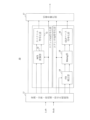
- FIG. 1 shows an example of the configuration of an encoding system.
- FIG. 1 is a diagram showing an example of a detailed configuration of an encoding system.
- FIG. 1 is a diagram showing another example of a detailed configuration of an encoding system.
- FIG. 11 is a flow diagram showing an example of a calculation process of an amplitude adjustment coefficient.
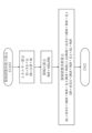
- FIG. 1 shows an example of an encoding process.
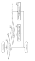
- FIG. 13 is a diagram showing an example of a coding mode determination process;
- FIG. 13 is a diagram showing another example of the encoding mode determination process.
- FIG. 1 is a flow diagram showing an example of a stereo encoding process.
- FIG. 13 is a diagram showing an example of pseudo code for ITD correction processing.
- ITD Inter-channel time difference
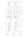
- FIG. 1 is a diagram showing an example of switching transition of coding modes in a coding system.
- FIG. 1 illustrates an example of a channel conversion transition in a coding system.
- FIG. 1 shows an example of the configuration of a decoding system.
- FIG. 1 is a diagram showing another example of a detailed configuration of an encoding system.
- FIG. 13 is a diagram showing another example of the encoding mode determination process.
- Patent document 1 discloses a highly efficient Modified Discrete Cosine Transform (MDCT) stereo encoding method that combines a Mid-Side (M/S) stereo method and a Left-Right (LR) stereo method. Also, for example, a method of switching between the M/S stereo method and the LR stereo method in transform encoding of a stereo signal is known (see, for example, patent documents 1 and 2).
- MDCT Modified Discrete Cosine Transform
- the MDCT coding (also called MDCT-based coding) shown in Patent Document 1 may not provide sufficient coding performance for audio signals at low bit rates.
- a "full mid-side coding mode (full M/S coding mode)" can be selected in which the M/S stereo method is set in all of the multiple subbands (also called frequency bands or spectral bands, for example) obtained by dividing the spectrum of the input stereo signal.
- the full mid-side coding mode when the full mid-side coding mode is selected, an MDCT-based coding method is applied, but depending on the bit rate, the use of Code Excited Prediction (CELP) coding (or called CELP-based coding) may improve the coding performance for the audio signal.
- CELP Code Excited Prediction
- the introduction of CELP coding can improve coding performance, but when coding audio signals using the M/S stereo system, the inter-channel time difference (ITD) is likely to affect coding performance. Therefore, when coding audio signals using the M/S stereo system, if the inter-channel time difference (ITD) is not zero, the coding performance of stereo signals using CELP coding may be degraded or insufficient.
- a method for improving the coding performance of coding audio signals at low bit rates is described.
- FIG. 1 is a diagram showing an example of the configuration of an encoding device (or called an “encoding system”) 10. As shown in FIG.
- the encoding device 10 may include, for example, a conversion/analysis/preprocessing/encoding control unit 11, an M/S conversion unit 12, a spectral encoding unit 13, an ITD correction unit 14, a mixing unit 15, a CELP-based encoding unit 16, and a switching multiplexing unit 17.
- the conversion/analysis/preprocessing/encoding control unit 11 may receive, for example, a stereo signal including an L channel (Left channel) signal and an R channel (Right channel) signal.
- the conversion/analysis/preprocessing/encoding control unit 11 may, for example, convert the L channel signal and the R channel signal into frequency domain signals and output the L channel signal and the R channel signal converted into the frequency domain to the M/S conversion unit 12.
- the conversion process in the conversion/analysis/preprocessing/encoding control unit 11 may be, for example, a process of converting a time domain signal into a frequency domain parameter (spectral parameter), such as a Fast Fourier Transform (FFT), a Discrete Fourier Transform (DFT) or an MDCT.
- FFT Fast Fourier Transform
- DFT Discrete Fourier Transform
- MDCT Discrete Fourier Transform
- the conversion/analysis/preprocessing/encoding control unit 11 may, for example, control the M/S conversion in the M/S conversion unit 12, and output information related to the M/S conversion (for example, referred to as "M/S conversion control information") to the M/S conversion unit 12.
- M/S conversion control information may include, for example, information regarding the presence or absence of LR-M/S conversion in the M/S conversion unit 12, or information regarding the subbands on which the LR-M/S conversion is performed.
- the M/S conversion control information is also output to the switching multiplexing unit 17.
- the conversion/analysis/preprocessing/encoding control unit 11 may, for example, output the L channel signal and the R channel signal in the time domain to the ITD correction unit 14.
- the conversion/analysis/preprocessing/encoding control unit 11 may, for example, perform control related to ITD correction and output control information related to ITD correction (for example, referred to as "ITD correction control information") to the ITD correction unit 14.
- the ITD correction control information may, for example, be information indicating an ITD correction value, or may be information for determining an ITD correction value in the ITD correction unit 14.
- the conversion/analysis/preprocessing/encoding control unit 11 may, for example, control mixing in the mixing unit 15 and output control information related to mixing (for example, referred to as "mixing control information") to the mixing unit 15.
- the mixing control information may include, for example, information related to parameters (an example of which will be described later) used for mixing in the mixing unit 15.
- the mixing control information is also output to the switching multiplexing unit 17.
- the conversion/analysis/preprocessing/encoding control unit 11 may also perform, for example, analysis processing to analyze the characteristics of the L channel signal and the R channel signal.
- the analysis processing may include, for example, Inter-channel Cross Correlation (ICC) analysis, Inter-channel Time Difference (ITD) analysis, Inter-channel Level Difference (ILD) analysis, or pitch analysis.
- ICC Inter-channel Cross Correlation
- ITD Inter-channel Time Difference
- ILD Inter-channel Level Difference
- pitch analysis or pitch analysis.
- the conversion/analysis/preprocessing/encoding control unit 11 may output, for example, information regarding the analysis results (for example, referred to as "analysis information") to the ITD correction unit 14 or other components.
- the conversion/analysis/preprocessing/encoding control unit 11 may also perform preprocessing such as pre-emphasis or auditory masking (or auditory weighting).
- the conversion/analysis/preprocessing/encoding control unit 11 may, for example, control switching of the encoding mode and output control information related to switching of the encoding mode (for example, referred to as "encoding mode information") to the switching multiplexing unit 17.
- the encoding mode information may include, for example, an encoding mode to be applied between encoding of a stereo signal in the frequency domain (for example, referred to as "stereo FD (Frequency Domain) encoding") and encoding of a stereo signal in the time domain (for example, referred to as "stereo TD (Time Domain) encoding"). As shown in FIG.
- the stereo FD encoding unit that performs the stereo FD encoding may include an M/S conversion unit 12 and a spectrum encoding unit 13 and the stereo TD encoding unit that performs the stereo TD encoding may include an ITD correction unit 14, a mixing unit 15, and a CELP-based encoding unit 16.
- the transform/analysis/preprocessing/encoding control unit 11 may include a first transform unit 101, an M/S determination unit 102, an ITD analysis unit 103, an ITD shift unit 104, a second transform unit 105, an FD/TD determination unit 106, and a control unit 107.
- the stereo FD encoding unit, stereo TD encoding unit, and switch multiplexing unit 17 are the same as those in FIG. 1.
- the first conversion unit 101 may receive, for example, a stereo signal including an L channel (left channel) signal and an R channel (right channel) signal.
- the first conversion unit 101 may convert, for example, each of the time domain L channel signal and R channel signal into a frequency domain signal, and output the L channel signal and R channel signal converted into the frequency domain to the stereo FD encoding unit and M/S determination unit 102.
- the time-frequency conversion process in the first conversion unit 101 may be, for example, a process of converting a time domain signal into a frequency domain parameter (spectral parameter), such as FFT, DFT, or MDCT, and is not limited to these.
- spectral parameter such as FFT, DFT, or MDCT
- the M/S determination unit 102 may receive, for example, a frequency domain stereo signal including an L channel signal and an R channel signal converted to the frequency domain, output from the first conversion unit 101.
- the M/S determination unit 102 estimates, for example, the number of bits required to encode the frequency domain stereo signal as an LR stereo signal and the number of bits required to encode the frequency domain stereo signal as an M/S stereo signal, and determines the stereo signal format that can be encoded with fewer bits, either the M/S stereo format or the LR stereo format. This determination may be performed for each frequency band, and a complete M/S encoding mode may be set when it is determined that all frequency bands are to be encoded using the M/S stereo format.
- the M/S determination unit 102 may output information on the determination result indicating whether the M/S stereo format or the LR stereo format is to be used, to the stereo FD encoding unit and the FD/TD determination unit 106, respectively.
- the method described in chapters 5.3.3.2.8.1.3 to 5.3.3.2.8.1.7 of Non-Patent Document 1 may be used, as disclosed in Patent Document 1.
- the ITD analysis unit 103 may receive, for example, a stereo signal including an L channel and an R channel.
- the ITD analysis unit 103 may calculate, for example, the inter-channel time difference (ITD) in the input stereo signal.
- the ITD analysis unit 103 may output information related to the calculated ITD (ITD information) to the stereo TD encoding unit and the ITD shift unit 104.
- the ITD shift unit 104 may receive, for example, a stereo signal including an L channel signal and an R channel signal.
- the ITD shift unit 104 may also receive ITD information output from the ITD analysis unit 103.
- the ITD shift unit 104 may use the ITD information input from the ITD analysis unit 103 to time shift the signal of one channel so that the time difference between the channels of the input stereo signal is eliminated. In general, the time shift is performed so that the other channel signal is aligned with the channel signal with a time delay, out of the L channel signal and the R channel signal in the time domain.
- the ITD shift unit 104 may output the stereo signal that has been subjected to the time shift processing to the second conversion unit 105.
- the second conversion unit 105 may, for example, convert the L channel signal and R channel signal after time shift processing (also called the stereo signal after time shift processing) into a frequency domain signal, and output the stereo signal after time shift processing converted into the frequency domain to the FD/TD determination unit 106.
- the conversion process in the second conversion unit 105 may be the same as the conversion process in the first conversion unit 101, or may be different.
- the FD/TD decision unit 106 may receive M/S decision information indicating whether to use the M/S stereo method or the LR stereo method from the M/S decision unit 102.
- the FD/TD decision unit 106 may also receive the stereo signal converted into the frequency domain and subjected to time shift processing from the second conversion unit 105.
- the FD/TD decision unit 106 may estimate the number of bits Bm required to encode the Mid channel signal and the number of bits "Bs" required to encode the Side channel signal when the stereo signal after time shift processing converted into the frequency domain is encoded as an M/S stereo signal, and may decide whether to perform FD stereo encoding or TD stereo encoding based on a numerical value calculated using Bm and Bs (for example, the value of Bm/(Bm+Bs)). Details of this decision will be described later.
- the FD/TD decision unit 106 may output encoding mode information indicating whether to select the FD stereo encoding mode or the TD stereo encoding mode to the control unit 107.
- the control unit 107 may receive, for example, encoding mode information indicating whether to select the FD stereo encoding mode or the TD stereo encoding mode from the FD/TD determination unit 106.
- the control unit 107 determines mixing control information based on the encoding mode information input from the FD/TD determination unit 106, for example, and outputs the mixing control information to the stereo TD encoding unit.
- the control unit 107 may change the encoding mode information from the FD encoding mode to the TD encoding mode, and output the final encoding mode information to the switching multiplexing unit 17.
- the input encoding mode information may be output as is to the switching multiplexing unit 17 as the final encoding mode information.
- FIG. 3 is a diagram showing another example of the configuration of the encoding device 10 including the conversion, analysis, preprocessing and encoding control unit 11 further including a voice/music determination unit 108 that determines whether the type of the input stereo signal is a voice signal, in contrast to the example of the configuration in FIG. 2 described above.
- the configuration other than the voice/music determination unit 108 is the same as in FIG. 2, so a description thereof will be omitted.
- the input to the voice/music determination unit 108 is not shown in FIG. 3, a stereo signal including an L channel (left channel) signal and an R channel (right channel) signal may be input, or an analysis result output by an analysis unit that inputs a stereo signal and performs some kind of analysis may be input.
- the voice/music determination unit 108 outputs information regarding whether the signal is a voice signal to the FD/TD determination unit 106.
- the FD/TD determination unit 106 uses the information input from the voice/music determination unit 108 to determine the encoding mode.
- the voice/music determination for example, the method disclosed in Patent Document 3 or Chapter 5.1.13.6 of Non-Patent Document 1 may be used.
- the speech/music determination unit 108 may be provided in the stereo TD encoding unit or the stereo FD encoding unit, in which case the past speech/music determination results may be input to the FD/TD determination unit 106.
- the M/S conversion unit 12 and the spectral encoding unit 13 may constitute a stereo FD encoding unit (e.g., corresponding to the second encoding unit) that performs stereo FD encoding.
- the M/S conversion unit 12 in FIG. 1 is not necessary when the result of the M/S conversion is output from the M/S determination unit 102 in FIG. 2.
- the M/S conversion unit 12 is included in the M/S determination unit 102, and in the stereo FD encoding unit, the stereo signal output from the M/S conversion unit 12 may be input to the spectral encoding unit 13 instead of the stereo signal output from the first conversion unit 101 in FIG. 2.
- the M/S conversion unit 12 receives, for example, the frequency domain L channel signal and R channel signal (e.g., spectral parameters) and M/S conversion control information from the conversion/analysis/preprocessing/encoding control unit 11.
- the M/S conversion unit 12 may perform LR-M/S conversion processing of the L channel spectral parameters and the R channel spectral parameters based on the M/S conversion control information.
- the M/S conversion unit 12 outputs, for example, the spectral parameters (2 channels) after the LR-M/S conversion processing to the spectral encoding unit 13.
- the M/S conversion unit 12 may perform LR-M/S conversion processing for each subband.
- the M/S conversion control information may include information indicating whether or not to perform LR-M/S conversion for each subband, and the M/S conversion unit 12 may perform LR-M/S conversion processing based on the M/S conversion control information.
- the M/S conversion control information may include information indicating whether or not to perform LR-M/S conversion in multiple subbands (e.g., some or all of the subbands), and the M/S conversion unit 12 may perform LR-M/S conversion processing based on the M/S conversion control information.
- the spectrum coding unit 13 for example, performs coding processing on the two-channel spectrum parameters input from the M/S conversion unit 12, and outputs the coding result (for example, called "stereo FD coding information") to the switching multiplexing unit 17.
- the coding processing performed by the spectrum coding unit 13 for example, the method shown in Chapter 5.3.3.2 of Non-Patent Document 1 may be used for the MDCT spectrum, as in Patent Document 1.
- the ITD correction unit 14, the mixing unit 15, and the CELP-based encoding unit 16 may constitute a stereo TD encoding unit (e.g., corresponding to the first encoding unit) that performs stereo TD encoding.
- the ITD correction unit 14 may receive, for example, the preprocessed time domain L channel signal and R channel signal, ITD correction control information, and analysis information from the conversion/analysis/preprocessing/encoding control unit 11.
- the ITD correction unit 14 may perform a correction process (e.g., a correction process that brings the absolute value of the ITD less than a threshold value) (e.g., a correction process that brings it closer to zero) (e.g., referred to as an ITD correction process) on the L channel signal and R channel signal based on the ITD correction control information.
- the ITD correction unit 14 may output the L channel signal and R channel signal after the ITD correction process to the mixing unit 15. An example of the ITD correction process in the ITD correction unit 14 will be described later.
- ITD correction processing is performed on the encoding side, but does not have to be performed on the decoding side (for example, restoration processing does not have to be performed on the decoding side).
- at least one of an upper limit and a lower limit may be set for the maximum number of shifts (for example, the number of samples) that can be corrected (for example, shifted).
- the angular resolution also called the perceived resolution of the direction
- the range of ITD correction may be set so that the angle of the arrival direction is within a width of about 30 degrees.
- the correctable range may be set to a range of up to ⁇ 3 samples.
- the range of ITD correction is not limited to ⁇ 3 samples and may be other values.
- the perceived resolution of the direction referred to when setting the range of ITD correction is not limited to 30 degrees.
- the ITD correction unit 14 may clip the ITD obtained by the ITD analysis at an upper or lower limit value, for example, if the ITD exceeds a set range.
- the encoding device 10 may also perform an ILD correction process to correct the ILD in the L channel signal and the R channel signal. For example, the encoding device 10 may adjust the amplitude of both channel signals so that the ILD between the L channel signal and the R channel signal after the ITD correction process is zero, i.e., the energy of both channel signals is equal. For example, the encoding device 10 may adjust the amplitude of both channel signals so that the energy of the L channel signal and the energy of the R channel signal have an average energy. When performing the amplitude adjustment, the encoding device 10 may perform the amplitude adjustment by gradually increasing the amount of amplitude adjustment from the start of the frame to avoid discontinuity between frames.
- the encoding device 10 may calculate an amplitude adjustment coefficient (e.g., a gain) and multiply each of the two channel signals after the ITD correction process by the calculated amplitude adjustment coefficient.
- an amplitude adjustment coefficient e.g., a gain
- the amplitude adjustment coefficient can be calculated, for example, as shown in FIG. 4.
- the procedure for calculating the amplitude adjustment coefficient includes an energy calculation step, an amplitude ratio calculation step, and an amplitude adjustment coefficient calculation step.
- the energy calculation step calculates the frame energy (EL and ER) of the L channel signal (L) after ITD correction processing and the R channel signal (R) after ITD correction processing, and outputs them to the amplitude ratio calculation step.
- the amplitude ratio calculation step calculates the square root of the ratio between EL and ER, and outputs it to the amplitude adjustment coefficient calculation step as the amplitude ratio between L and R (RLR).
- the amplitude ratio calculation step if the average energy, power, or amplitude of both channel signals does not exceed a predetermined threshold, the amplitude ratio may not be calculated and may be output as 1. This prevents amplitude adjustment processing from being performed on low-level signals, making it possible to skip unnecessary processing.
- the amplitude adjustment coefficient calculation step calculates the square root of the ratio of the average of the square of RLR and 1 (e.g., 0.5 ⁇ (RLR ⁇ RLR + 1)) to the square of RLR (e.g., RLR ⁇ RLR), and sets this as the amplitude adjustment coefficient (GL) for the L channel.
- the amplitude adjustment coefficient calculation step also calculates the amplitude adjustment coefficient (GR) for the R channel by multiplying GL by RLR.
- GL may be clipped to the upper threshold if it exceeds the upper threshold, or may be clipped to the lower threshold if it is below the lower threshold. In this way, by keeping the amplitude adjustment coefficient within a specific range, it is possible to prevent the amplitude change due to the amplitude adjustment from becoming too large.
- the amplitude adjustment coefficient may be gradually changed from the amplitude adjustment coefficient used in the immediately preceding frame to the amplitude adjustment coefficient calculated for the current frame, so that the amplitude-adjusted signal is smoothly connected between frames.
- the procedure for calculating the amplitude adjustment coefficient is not limited to the process shown in FIG. 4.
- the amplitude adjustment coefficient is not limited to the value obtained by the process shown in FIG. 4, but may be any value that is calculated so that the amplitudes (or energies) of both channel signals are equal.
- the encoding device 10 may perform processing to bring the ITD closer to zero (e.g., ITD correction processing) in addition to processing to bring the ILD closer to zero (e.g., ILD correction processing).
- ITD correction processing processing to bring the ILD closer to zero
- ILD correction processing processing to bring the ILD closer to zero
- the mixing unit 15 may receive, for example, the L channel signal and the R channel signal after ITD correction processing from the ITD correction unit 14, and may receive mixing control information from the conversion/analysis/preprocessing/encoding control unit 11.
- the mixing unit 15 performs mixing processing of the L channel signal and the R channel signal based on the mixing control information, for example, and outputs the two-channel signal after mixing processing to the CELP-based encoding unit 16. An example of the mixing processing in the mixing unit 15 will be described later.
- the CELP-based coding unit 16 may code each of the two-channel signals (e.g., M/S signals obtained by converting the input stereo signal after ITD correction) input from the mixing unit 15 using a CELP-based codec (e.g., multimode coding, multimode codec, or multimode mono codec) that has a configuration for switching between CELP coding and MDCT coding, such as the Enhanced Voice Services (EVS) codec (see non-patent document 1).
- the CELP-based coding unit 16 may output a signal (e.g., "stereo TD coding information") multiplexed with the coding results of each channel to the switching multiplexing unit 17.
- the switching multiplexing unit 17 may, for example, multiplex the information to be sent out from among the M/S conversion control information input from the conversion/analysis/preprocessing/encoding control unit 11, the mixing control information, the stereo FD encoding information input from the spectrum encoding unit 13, and the stereo TD encoding information input from the CELP-based encoding unit 16 based on the encoding control information input from the conversion/analysis/preprocessing/encoding control unit 11, and output the multiplexed information to a transmission path such as a communication channel, or a recording medium such as a storage medium.
- either the stereo FD encoding information or the stereo TD encoding information may be input to the switching multiplexing unit 17 based on the encoding control information.
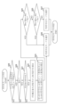
- FIG. 5 is a flowchart showing an example of a processing procedure of the encoding device 10.
- the conversion/analysis/preprocessing/encoding control unit 11 performs, for example, conversion processing, analysis processing, and preprocessing on the L channel signal and the R channel signal (S1).
- the encoding device 10 determines whether the target frame is a frame that uses stereo TD coding (S2). For example, the encoding device 10 may determine whether the conditions for applying stereo TD coding are met. Or, for example, the encoding device 10 may determine whether the conditions for applying stereo FD coding are met.
- the encoding device 10 may determine whether or not to use stereo TD encoding based on, for example, the results of an analysis of the inter-channel correlation (ICC) between the L channel and the R channel, or based on an LR/MS decision algorithm (for example, a method for determining M/S conversion control) used in stereo FD encoding. For example, the encoding device 10 may determine that the conditions for applying stereo TD encoding are met when the inter-channel correlation (ICC) is high (for example, when the ICC value is equal to or greater than a threshold), and may determine that the conditions for applying stereo TD encoding are not met when the inter-channel correlation (ICC) is low (for example, when the ICC value is less than a threshold).
- ICC inter-channel correlation
- ICC inter-channel correlation
- the encoding device 10 may analyze whether the type of the input stereo signal is an audio signal.
- the condition for applying stereo TD coding may be based on the type of the input stereo signal. For example, the encoding device 10 may determine that the condition for applying stereo TD coding is met if the type of the input stereo signal is an audio signal, and may determine that the condition for applying stereo TD coding is not met if the type of the input stereo signal is not an audio signal.
- the condition for applying stereo TD coding may be based on, for example, the inter-channel time difference (ITD) in the input stereo signal.
- the encoding device 10 may determine that the condition for applying stereo TD coding is met when the ITD value obtained from the ITD analysis is within a preset threshold range near 0, and may determine that the condition for applying stereo TD coding is not met when the ITD value is outside the threshold range.
- the preset range may be, for example, a range that is expanded to within about 50% of the range that can be corrected by the ITD correction process described above (for example, a range based on perceptual resolution).
- the preset range may be set so that when the ITD changes from inside to outside the specified range, or when the ITD changes from outside to inside the specified range, the determination result is changed after the state after the change has continued for a specified number of frames. This is intended to avoid a situation in which stereo FD encoding and stereo TD encoding frequently switch between frames when the input signal has an ITD that changes near the boundary of the ITD range.
- the condition for applying stereo TD encoding may be based on, for example, the bit rate for the input stereo signal.
- the encoding device 10 may determine that the condition for applying stereo TD encoding is met when the bit rate is equal to or lower than a threshold, and may determine that the condition for applying stereo TD encoding is not met when the bit rate is greater than the threshold.
- the conditions for applying stereo TD coding may be based on at least one of the above-mentioned ICC, LR/MS determination algorithm, type of input stereo signal, ITD, and bit rate.
- the condition for applying stereo TD encoding may be based on a numerical value calculated using, for example, the number of bits estimated to be required for encoding the Mid channel signal and the number of bits estimated to be required for encoding the Side channel signal.
- the FD/TD determination unit 106 in Figs. 2 and 3 may determine the encoding mode using, for example, the processing flow shown in Fig. 6 or 7.
- the FD/TD determination unit 106 checks whether the M/S determination result input from the M/S determination unit 102 is the complete M/S encoding mode (S21), and if it is not the complete M/S encoding mode (S21: NO), it selects the FD encoding mode (S26).
- the FD/TD decision unit 106 calculates an M/S stereo signal from the stereo signal converted to the frequency domain that is input from the second conversion unit 105 (S22). Note that in Figs. 2 and 3, the calculation of the M/S stereo signal is performed after conversion to the frequency domain, but it is also possible to calculate the M/S stereo signal in the time domain first, and then convert it to the frequency domain.
- the FD/TD determination unit 106 estimates the number of bits Bm required to encode the Mid channel signal of the M/S stereo signal, and the number of bits Bs required to encode the Side channel signal (S23).
- the method described in Patent Document 1 can be used.
- the FD/TD determination unit 106 determines whether the value of Bm/(Bm+Bs) exceeds the threshold Thi (or is equal to or greater than the threshold Thi) (S24), and if it exceeds Thi (or is equal to or greater than Thi) (S24: YES), selects the FD encoding mode (S26).
- Thi may be a value close to 1, for example, set to 0.90. If the value of Bm/(Bm+Bs) exceeds the threshold Thi or is equal to or greater than the threshold Thi, it means that most of the input signal is included on the Mid channel side, and it is a stereo signal close to dual mono. For such stereo signals, the Mid channel signal can be encoded with a sufficient number of bits, so the FD encoding mode is selected.
- the value of the threshold Thi is not limited to 0.90, and may be, for example, 0.85.
- the FD/TD determination unit 106 determines whether Bm/(Bm+Bs) is below the threshold Tlo (or is equal to or less than the threshold Tlo) (S25), and if it is below Tlo (or is equal to or less than Tlo) (S25: YES), selects the FD encoding mode (S26).
- Tlo may be a value of 0.5 or slightly above 0.5, and is set to 0.65, for example.
- the TD coding mode which has the aspect of time-domain waveform coding, is prone to degradation of stereo localization and subjective sound quality due to coding errors, so the FD coding mode is more advantageous. For this reason, the FD/TD decision unit 106 selects the FD coding mode.
- the value of the threshold Tlo is not limited to 0.65, and may be, for example, 0.60.
- the FD/TD decision unit 106 selects the TD coding mode (S27).
- S27 the TD coding mode
- the FD/TD decision unit 106 selects the TD coding mode, which can code the audio signal with high quality even with a smaller number of bits.
- FIG. 7 shows a processing flow in which a step (S28) of determining whether the type of the input signal is an audio signal is added as the first processing step to the determination procedure of FIG. 6. If the type of the input signal is determined to be an audio signal (S28: YES), the FD/TD determination unit 106 proceeds to a step (S21) of determining whether the mode is the complete M/S encoding mode. On the other hand, if the type of the input signal is determined to be not an audio signal (S28: NO), the FD/TD determination unit 106 determines that the FD encoding mode should be selected (S26).
- the FD/TD determination unit 106 may change the thresholds Thi and Tlo and proceed to the process of S21 without determining that the FD encoding mode is selected.
- at least one of the thresholds Thi and Tlo may be changed so that the difference between the thresholds Thi and Tlo becomes smaller (for example, so that the values approach each other). For example, if the initial value of Thi is 0.90 and the initial value of Tlo is 0.65, Thi may be changed to 0.68 and Tlo to 0.66.
- Thi 0.90 after 22 frames.
- the value by which Thi is increased each frame and the upper limit value may be determined.
- the value by which Tlo is decreased each frame and the lower limit value may be determined. In this way, even if the speech/music determination unit 108 exists only in the stereo TD encoding unit, the encoding device 10 can switch between stereo TD encoding and stereo FD encoding according to the input signal.
- the period (e.g., the number of frames) during which the interval between Thi and Tlo (e.g., at least one value of Thi and Tlo) is changed, and the amount of change are not limited to the above examples.
- the period during which the interval between Thi and Tlo is gradually changed may be equal (or periodic) or unequal (or non-periodic).
- the amount by which the interval between Thi and Tlo is changed for each specified period may be the same or different.
- the step of determining whether the type of input signal is an audio signal does not have to be the first step in the process flow of FIG. 7, and may be incorporated into the step (S21) of determining whether the mode is full M/S encoding mode (for example, determining whether the signal is an audio signal and in full M/S encoding mode).
- the determination of whether the type of input signal is an audio signal is performed, for example, by the audio/music determination unit 108 in FIG. 3, and information on the determination result is input to the FD/TD determination unit 106.
- the encoding device 10 determines that the TD encoding mode is to be applied, it converts the LR stereo signal into an M/S stereo signal, and encodes the Mid and Side signals using a CELP-based encoder. Note that in FIG. 6 and FIG. 7, a case has been described in which it is determined whether the value of Bm/(Bm+Bs) exceeds the threshold Tlo (or is equal to or greater than Tlo) and then whether it exceeds the threshold Thi (or is equal to or less than Thi), but the order may be reversed, or it may be determined at once that the value is within a certain numerical range.
- the TD encoding mode can be selected only when there is a definite advantage to performing CELP encoding, and encoding performance can be improved.
- the encoding device 10 determines that the frame uses stereo TD encoding (S2: YES), it performs stereo TD encoding processing (S3).
- S3 stereo TD encoding processing
- the encoding device 10 may determine that the stereo audio signal is converted from an LR stereo signal to an M/S stereo signal, and the Mid signal and Side signal are encoded using a CELP-based encoder (for example, the CELP-based encoding unit 16).
- the coding device 10 can improve the coding performance of the audio signal by performing CELP-based stereo TD coding when the conditions are met.
- the coding device 10 may apply CELP-based coding to the Mid signal and a coding method other than CELP-based coding to the Side signal.
- stereo FD coding processing is performed (S4).
- FIG. 8 is a flow diagram showing an example of a processing procedure for stereo TD encoding (for example, the processing of S3 shown in FIG. 5).
- the encoding device 10 performs an ITD correction process on the L channel signal and the R channel signal to correct the ITD (absolute value) to a threshold or less (S31).
- the encoding device 10 performs a mixing process (e.g., LR to M/S conversion process in the time domain) on the R channel signal and the L channel signal after ITD correction (S32).
- a mixing process e.g., LR to M/S conversion process in the time domain
- the encoding device 10 performs encoding processing for each channel, for example, on the two channel signals after the mixing processing (S33).
- the ITD correction process is performed, for example, after a frame to be coded is determined to be a frame to be coded using stereo TD coding (e.g., referred to as a "stereo TD coded frame").
- stereo TD coded frames can be classified into the following three types.
- the first stereo TD frame (hereinafter also referred to as the "first frame") after switching from a frame where stereo FD encoding processing is performed (for example, called a "stereo FD encoding frame").
- a frame followed by a stereo TD encoded frame (hereinafter also referred to as a "second frame")
- the second frame may be, for example, a frame whose preceding and following frames are not stereo FD frames.
- the last stereo TD encoded frame (hereinafter also referred to as the "third frame”)
- the third frame may be a frame that switches to a stereo FD encoded frame in the next frame.
- the method of ITD correction processing for each of these three types of frames may be different.
- an MDCT-based coding mode may be selected in the CELP-based coding unit 16, as described below.
- an ITD correction process may be performed to bring it closer to zero.
- the immediately preceding frame is a stereo TD encoded frame, and it is highly likely that ITD correction processing has already been applied.
- the encoding device 10 may perform correction processing, for example, to gradually delay (shift the waveform toward the future on the time axis) or gradually advance (shift the waveform toward the past on the time axis) the signal of one channel depending on the difference (change) between the ITD in the immediately preceding frame and the ITD in the current frame.
- the encoding device 10 does not need to perform ITD correction processing that causes a gradual change (for example, it may maintain the previous shift amount).
- the encoding device 10 may set an upper limit on the amount of ITD correction (e.g., the number of samples by which the signal of one channel is delayed) in order to suppress abrupt changes in the signal due to the correction process.
- the encoding device 10 may set (e.g., limit) the upper limit (e.g., maximum value) of the number of samples that can be corrected per frame to one sample. In this case, it takes two or more frames to perform ITD correction of more than one sample.
- the encoding mode since the encoding mode will switch to stereo FD encoding in the subsequent frame, it is advisable to perform an ITD correction process to restore the corrected ITD.
- the setting of an upper limit e.g., a restriction or limitation
- the encoding device 10 performs a process of gradually advancing (shifting in the past on the time axis) the channel that was delayed (shifted in the future direction on the time axis) by the ITD correction process to return it to its original position.
- the encoding device 10 may perform ITD correction to gradually shift the time signal within one sample in multiple stereo TD encoding frames (e.g., a section) other than the third frame that immediately precedes the frame in which stereo FD encoding is performed.
- stereo TD encoding frames e.g., a section
- FIG. 9 is a flow diagram showing an example of the processing procedure of the above-mentioned ITD correction process (e.g., the process of S31 shown in FIG. 8).
- the encoding device 10 determines, for example, whether the frame is the first frame at which to switch to stereo TD encoding (S311).
- encoding device 10 does not need to perform ITD correction processing (e.g., ends ITD correction processing). Note that, as described above, encoding device 10 may perform ITD correction processing on this frame. In this case, the processing of S311 does not need to be performed, and the first frame may be treated in the same way as the second frame.
- the coding device 10 determines, for example, whether the frame is the third frame at which coding will switch to stereo FD coding (S312).
- the encoding device 10 may perform an ITD correction process (S313).
- the encoding device 10 may perform a process to restore the ITD for the ITD-corrected channel (S314). This process ends the ITD correction process by ultimately outputting the input signal as is.
- Figure 10 is a diagram showing the process flow of the ITD correction process shown in Figure 9 using pseudo program code.
- the signal advance e.g., shifting towards the past on the time axis
- delay e.g., shifting towards the future on the time axis
- the signal advance may be performed with a resolution of less than one sample, for example to achieve a smooth change.
- This can be done using an interpolation filter that interpolates between samples.
- it can be implemented in a similar manner to the fractional delay long-term prediction filter used in the known CELP codec.
- Fig. 11 shows an example of a coefficient set for an interpolation filter (e.g., an FIR filter) that uses a total of 13 points, six samples before and after, to perform interpolation with 1/24 sample accuracy.
- the interpolation filter is equivalent to the impulse response of a delay filter that delays a signal with 1/24 sample accuracy, inverted on the time axis. Note that in Fig. 11, a filter with a coefficient set consisting of 0s and 1s is shown for convenience, but it does not need to be implemented (for example, since the input and output do not change or are merely shifted by one sample, it does not need to be applied as filter processing).
- FIG. 12 is a diagram showing an example of switching of the encoding mode over five frames in which the above-mentioned three types of stereo TD encoded frames and stereo FD encoded frames are switched. Time passes from the left end to the right end of Fig. 12, and the frames are separated by dashed lines.
- the leftmost frame is the second frame of the stereo TD encoded frames.
- the second frame from the left is the stereo TD encoded frame (third frame) immediately before switching to a stereo FD encoded frame.
- the third frame from the left is a stereo FD encoded frame.
- the fourth frame from the left is the stereo TD encoded frame (first frame) immediately after switching from a stereo FD encoded frame.
- the fifth frame from the left (rightmost frame), like the leftmost frame, is the second frame of the stereo TD encoded frames.
- the encoding device 10 may perform an M/S->LR transition mixing process (an example will be described later).
- an MDCT-based encoding mode of the same type as the encoding mode in stereo FD encoding may be set for encoding.
- the MDCT-based encoding mode may include, for example, an MDCT-based Transform coded excitation (TCX) mode in the EVS codec.
- the encoding device 10 may perform a mixing process of LR ⁇ M/S transition (an example will be described later).
- LR ⁇ M/S transition for example, an MDCT-based encoding mode of the same type as the encoding mode in stereo FD encoding may be set for encoding in order to make the connection with the immediately preceding stereo FD encoding frame seamless (or smooth).
- the encoding device 10 may perform MDCT-based encoding in the stereo TD encoding mode in frames adjacent to a frame in which the stereo FD encoding mode is applied, among a plurality of consecutive frames (e.g., a section) in which the stereo TD encoding mode is applied.
- the encoding device 10 may perform encoding based on an encoding mode in stereo FD encoding (e.g., an MDCT-based encoding mode) in at least one of an M/S->LR transition section in which stereo TD encoding switches to stereo FD encoding and an LR->M/S transition section in which stereo FD encoding switches to stereo TD encoding.
- an encoding mode in stereo FD encoding e.g., an MDCT-based encoding mode
- FIG. 13 is a diagram showing an example of mixing processing (encoding-side processing) and inverse mixing processing (decoding-side processing) corresponding to the switching transition between stereo TD encoding and stereo FD encoding shown in FIG. 12.
- Time progresses from the left end to the right end of FIG. 13, and frames are separated by dashed lines.
- the types of the five frames shown in FIG. 13 (for example, a stereo FD-encoded frame and any of the first to third frames of a stereo TD-encoded frame) are the same as the example shown in FIG. 12.
- the leftmost frame and the rightmost frame that correspond to the second frame of the consecutive stereo TD encoded frames may undergo general LR to M/S conversion processing.
- the channel conversion process (mixing process) is expressed, for example, by the following equation (1).
- Ln and Rn respectively represent the L channel signal and the R channel signal before conversion processing
- subscript n represents time (sample number)
- Mn and Sn respectively represent the M channel signal and the S channel signal after conversion processing.
- the second frame from the left which corresponds to the third frame corresponding to the M/S ⁇ LR transition section, may be subjected to channel conversion processing (mixing processing) expressed by the following equation (2).
- N indicates the frame length (or the transition section length).
- the transition section length N may be, for example, shorter or longer than one frame.
- the stereo signal gradually transitions from an M/S signal to an LR signal over time n.
- the fourth frame from the left which corresponds to the first frame corresponding to the LR ⁇ M/S transition section, may be subjected to channel conversion processing (mixing processing) expressed by the following equation (3).
- N indicates the frame length (or the transition section length).
- the transition section length N may be, for example, shorter or longer than one frame.
- the stereo signal gradually transitions from an LR signal to an M/S signal over time n.
- FIG. 14 is a diagram showing an example of the configuration of a decoding device (or a "decoding system") 20. As shown in FIG.
- the decoding device 20 may include, for example, a separation switching unit 21, a spectral decoding unit 22, an inverse M/S conversion unit 23, an inverse conversion unit 24, a CELP-based decoding unit 25, an inverse mixing unit 26, and a switching unit 27.
- the separation switching unit 21 receives multiplexed encoded information, for example, from a transmission path such as a communication channel or a recording medium such as a storage medium.
- the separation switching unit 21 may, for example, separate the encoded information into multiple pieces of control information and switch the output destination of the separated control information.
- the separation switching unit 21 may output the stereo FD encoding information (e.g., spectral encoding information) to the spectral decoding unit 22 and output the M/S conversion control information to the inverse M/S conversion unit 23.
- stereo FD encoding information e.g., spectral encoding information
- the separation switching unit 21 may output the stereo TD encoding information (e.g., the encoding information of the CELP-based encoding unit 16) to the CELP-based decoding unit 25 and output the mixing control information to the inverse mixing unit 26.
- the stereo TD encoding information e.g., the encoding information of the CELP-based encoding unit 16
- the separation switching unit 21 may also output information indicating, for example, whether stereo FD coding information or stereo TD coding information has been transmitted (or whether stereo FD coding or stereo TD coding has been applied) to the switching unit 27.
- the spectral decoding unit 22 and the inverse M/S transform unit 23 may constitute a stereo FD decoding unit that performs decoding of stereo encoded information in the frequency domain (for example, referred to as "stereo FD decoding").
- the spectrum decoding unit 22 for example, inputs the spectrum coding information output from the separation switching unit 21, decodes the two-channel spectrum information, and outputs it to the inverse M/S conversion unit 23.
- the inverse M/S transform unit 23 inputs the two-channel decoded spectrum output from the spectrum decoding unit 22 and the M/S transform control information output from the separation switching unit 21, performs an inverse M/S transform on the two-channel decoded spectrum based on the M/S transform control information, and outputs the LR stereo spectrum (e.g., MDCT spectrum) to the inverse transform unit 24.
- the LR stereo spectrum e.g., MDCT spectrum
- the inverse transform unit 24 inputs, for example, the LR stereo signal (MDCT spectrum) output from the inverse M/S transform unit 23, performs inverse transform (for example, Inverse MDCT (IMDCT)) processing, and outputs the LR stereo signal (time signal) to the switching unit 27.
- inverse transform for example, Inverse MDCT (IMDCT)
- IMDCT Inverse MDCT
- the CELP-based decoding unit 25 and the inverse mixing unit 26 may constitute a stereo TD decoding unit that performs decoding of stereo encoded information in the time domain (e.g., called "stereo TD decoding").
- the CELP-based decoding unit 25 inputs the coding information of the CELP-based coding unit 16 output from the separation switching unit 21, decodes the two-channel audio signal, and outputs it to the inverse mixing unit 26.
- the inverse mixing unit 26 receives, for example, the two-channel decoded audio signals output from the CELP-based decoding unit 25, and performs an inverse mixing process on the two-channel decoded audio signals based on the mixing control information output from the separation switching unit 21, reconstructs the LR stereo signals, and outputs them to the switching unit 27.
- the switching unit 27 for example, inputs information output from the separation switching unit 21, and depending on the information, inputs the decoded LR stereo signals from either the inverse conversion unit 24 or the inverse mixing unit 26, and outputs them as the final LR stereo signals (for example, an L channel signal and an R channel signal).
- the decoding device 20 does not need to perform processing corresponding to the ITD correction processing performed in stereo TD encoding (e.g., inverse correction processing to return the corrected ITD to its original state).
- FIG. 13 An example of the inverse mixing process corresponding to the switching transition between stereo TD decoding and stereo FD decoding is shown in FIG. 13.
- the leftmost frame and the rightmost frame corresponding to the second frame of the consecutive stereo TD encoded frames may be subjected to a general M/S ⁇ LR conversion process.
- the channel conversion process (inverse mixing process) is expressed by, for example, the following equation (4).
- the second frame from the left which corresponds to the third frame corresponding to the M/S ⁇ LR transition section, may be subjected to a channel conversion process (inverse mixing process) expressed by the following equation (5).
- the decoded stereo signal gradually transitions from an M/S signal to an LR signal as time n passes.
- the fourth frame from the left which corresponds to the first frame corresponding to the LR ⁇ M/S transition section, may be subjected to channel conversion processing (inverse mixing processing) expressed by the following equation (6).
- the decoded stereo signal gradually transitions from an LR signal to an M/S signal as time n passes.
- the second embodiment is different from the first embodiment in that it includes a means for determining whether or not at least a part of the main components of an input signal is outside the core band of CELP coding used in stereo TD coding, and the result of the determination is used to control switching of coding modes.
- the first embodiment is provided with a configuration in which stereo FD coding as disclosed in Patent Document 1 is switched to stereo TD coding using CELP-based coding when the following three conditions are satisfied: 1) Full M/S coding mode is determined (using M/S coding in the entire frequency band is determined to be more efficient than using LR coding) 2) The ratio of the number of bits required to encode the Mid channel to the number of bits required to encode both the Mid and Side channels is within a predetermined range. 3) The input stereo signal is determined to be a speech signal (the input stereo signal strongly exhibits the characteristics of a speech signal).
- bandwidth extension technology is sometimes used to code high-frequency band components in order to achieve high-quality sound at a low bit rate.
- Bandwidth Extension and Intelligent Gap Filling used in Non-Patent Document 1 efficiently code high-frequency band components using a model that uses low-frequency band components to generate high-frequency band signals.
- the low-frequency band is coded using core coding
- the high-frequency band is coded using bandwidth extension coding.
- the frequency band coded using core coding is referred to as the "core band”
- the frequency band coded using bandwidth extension coding is referred to as the "extended band.”
- band extension technology does not faithfully encode high-frequency band (extended band) components
- encoding errors are likely to occur in the high-frequency band components.
- the area in which the encoding errors occur is not the LR stereo signal area but the M/S stereo signal area or an area in the middle of the transition between the two areas, the encoding errors may be amplified by the conversion process to the LR stereo signal, resulting in artifacts that are audible problems.
- the encoding device when the encoding device uses CELP-based encoding using the band extension encoding for stereo TD encoding, it determines whether the extended band contains the main components of the input signal, and if so, performs encoding mode switching control to select stereo FD encoding rather than stereo TD encoding.
- FIG. 15 is a diagram showing another example of the configuration of the encoding device 10 including the conversion/analysis/preprocessing/encoding control unit 11 further including a main band determination unit 109 for determining whether or not the main component of the input stereo signal exists in the extension band, in contrast to the example of the configuration of FIG. 3 described in the first embodiment.
- the configuration other than the main band determination unit 109 is the same as that of FIG. 3, so the description is omitted.
- a stereo signal including an L channel (Left channel) signal and an R channel (Right channel) signal may be input, or an analysis result output by an analysis unit that inputs a stereo signal and performs some analysis may be input.
- the main band determination unit 109 outputs information regarding whether or not at least a part of the main component of the input signal exists in the extension band (of the CELP-based coding used in the stereo TD coding) to the FD/TD determination unit 106.
- the FD/TD determination unit 106 uses the information input from the main band determination unit 109 to determine the coding mode.
- the main band determination unit 109 divides an input signal that has been frequency transformed (e.g., MDCT transformed) into multiple bands, calculates the energy of each band, calculates the ratio of the sum of the band energies included in the extension band to the sum of the band energies included in the core band and the extension band, and determines whether or not the main component of the input signal is present in the extension band based on whether the calculated ratio exceeds a predetermined threshold.
- frequency transformed e.g., MDCT transformed
- Fig. 16 shows a process flow in which a step (S29) of determining whether or not the main component of the input signal is present in the extended band is added as the first processing step to the determination procedure of Fig. 7.
- the order of the three determination steps (S21, S28, S29) is not limited, but in the case of stereo FD coding as shown in Patent Document 1, the determination of whether or not it is complete M/S coding is always performed, so if step S21 is performed first, it is not necessary to perform step S28 or step S29 unnecessarily.
- the FD/TD decision unit 106 proceeds to a step of deciding whether the input signal is a speech signal (S28). On the other hand, if the main component of the input signal exists in the extension band (if the main component of the input signal does not fall within the core band of CELP-based coding, S29: NO), the FD/TD decision unit 106 decides to select the FD coding mode (S26).
- the step of determining whether the main component of the input signal is in the extended band does not have to be the first step in the processing flow of FIG. 16. For example, it may be after the step (S21) of determining whether the mode is complete M/S encoding.
- the three determination steps (S21, S28, S29) can be performed in any order, and the determination may be made based on the logical product of the three conditions (whether the mode is complete M/S encoding, the signal is a voice signal, and the main component is in the extended band).
- the determination of whether the main component of the input signal is in the extended band is performed, for example, by main band determination unit 109 in FIG. 15, and information on the determination result is input to FD/TD determination unit 106.
- the encoding device 10 determines that the TD encoding mode is to be applied, it converts the LR stereo signal into an M/S stereo signal for the stereo audio signal, and encodes the Mid and Side signals using a CELP-based encoder. Note that in FIG. 15, a case has been described in which it is determined whether the value of Bm/(Bm+Bs) exceeds the threshold Tlo (or is equal to or greater than Tlo) and then whether it exceeds the threshold Thi (or is equal to or less than Thi), but the order may be reversed, or it may be determined at once that the value is within a certain numerical range.
- the TD encoding mode can be selected only when there is a definite advantage to performing CELP encoding, and encoding performance can be improved.
- the condition for switching may be that the mode to be switched to has been selected (by the above-mentioned determination procedure) for a certain number of frames in the past.
- the coding device 10 holds the number of frames until the mode is switched as a counter, and decrements the counter by one when an coding mode different from that used in the immediately previous frame is selected, and increments the counter by one when the same mode as that used in the immediately previous frame is selected, and switches modes when the counter becomes 0 or less.
- the encoding device 10 since the FD coding mode is the default, the encoding device 10 initially sets the counter to an initial value (e.g., 20) assuming that the FD coding mode had been selected in the past. If the encoding device 10 determines that the first frame is the TD coding mode, it decrements the counter by 1 to make it 19. In this case, since the counter is not 0 or less, the encoding device 10 does not switch the coding mode even if the determination result is the TD coding mode, and performs coding using the FD coding mode. The encoding device 10 switches to the TD coding mode in a frame where the TD coding mode continues to be determined in subsequent frames and the counter becomes 0 or less.
- an initial value e.g. 20
- the reset value is the number of frames required to switch from TD coding to FD coding, and may be the same as when switching from FD coding to TD coding (20 in the previous example), or may be reduced (e.g., to 10) to prioritize FD coding.
- the number of frames required to switch to FD coding may also be changed depending on whether TD coding is likely to be selected for subsequent frames. For example, if the value of Bm/(Bm+Bs) when switching to TD coding is large (e.g., greater than 0.8), the coding device 10 may determine that there is a high possibility that TD coding will be selected for subsequent frames as well, and may reset the counter to a longer value (e.g., to 20); otherwise (the value of Bm/(Bm+Bs) is small (e.g., less than 0.8) but the TD coding mode is selected), the counter may be reset to a shorter value (e.g., to 10).
- the counter may be decremented by 2 (or more) instead of 1 in order to reduce the number of frames required to switch to the TD coding mode. In this case, the counter may be incremented by 1 if the same coding mode as that used in the previous frame is selected.
- the encoding device 10 determines whether to apply the stereo TD encoding mode or the stereo FD encoding mode based on a numerical value calculated using the number of bits (Bm) estimated to be required for encoding the Mid channel and the number of bits (Bs) required for encoding the Side channel.
- the encoding device 10 converts the stereo signal into an M/S signal and applies CELP encoding to the Mid channel signal (M signal), and when it is determined that the stereo FD encoding mode is to be applied, it performs spectral encoding on the stereo signal.
- M signal Mid channel signal
- the encoding device 10 may decide to apply a stereo TD encoding mode (e.g., CELP-based encoding).
- a numerical value e.g., Bm/(Bm+Bs)
- a second threshold e.g., Thi
- the encoding device 10 may decide to apply a stereo FD encoding mode.
- the numerical value e.g., Bm/(Bm+Bs)
- the first threshold e.g., Tlo
- the second threshold e.g., Thi
- the encoding device 10 can determine whether a stereo signal is advantageous for CELP-based encoding based on whether the ratio of the number of bits required to encode the Mid channel out of the number of bits required to encode the M/S stereo signal is within a predetermined range (for example, 65% to 85%). In addition, the encoding device 10 may determine whether a stereo signal is advantageous for CELP-based encoding when, for example, the stereo signal exhibits characteristics of a speech signal.
- the encoding device 10 can accurately determine cases in which the encoding performance for the speech signal can be improved by using CELP-based encoding rather than the MDCT-based encoding method. Therefore, according to this embodiment, the encoding device 10 can improve the encoding performance of the speech signal by using CELP encoding at a low bit rate.
- the encoding device 10 corrects the inter-channel time difference (ITD) between the L channel and R channel in the input stereo signal to a threshold value or less (for example, close to 0), and performs encoding on the M/S signal after correcting the ITD.
- ITD inter-channel time difference
- the ITD when encoding an audio signal using the M/S stereo method, the ITD can be set to near zero, suppressing the effect of the ITD on encoding performance and improving the encoding performance of a stereo signal using CELP encoding. Furthermore, in this embodiment, the ITD correction process is performed by encoding device 10 and not by decoding device 20. Therefore, information related to ITD correction does not need to be transmitted to decoding device 20, and an increase in the amount of encoding information or the amount of processing by decoding device 20 can be suppressed.
- the "full M/S encoding mode" is selected as an example when the input stereo signal is determined to be suitable for encoding using only the M/S stereo method, but this is not limiting.
- the decision to select the full M/S encoding mode may be determined based on whether the proportion of bands determined to use the M/S stereo method among multiple bands (subbands) in the frequency spectrum of the input stereo signal is equal to or greater than a threshold.
- the full M/S encoding mode may be selected when the proportion of bands determined to use the M/S stereo method is equal to or greater than a threshold.
- the decision to select the full M/S encoding mode may be determined based on whether it is determined that the M/S stereo method is to be used in all of the multiple bands of the frequency spectrum of the stereo signal converted to the frequency domain.
- the full M/S encoding mode may be selected when it is determined that the M/S stereo method is to be used in all of the multiple bands.
- parameters used in the above embodiment such as the number of frames, number of samples, resolution angle, and threshold value, are merely examples, and other values may be used.
- Each functional block used in the description of the above embodiment may be realized partially or entirely as an LSI, which is an integrated circuit, and each process described in the above embodiment may be controlled partially or entirely by one LSI or a combination of LSIs.
- the LSI may be composed of individual chips, or may be composed of one chip so as to include some or all of the functional blocks.
- the LSI may have data input and output.
- the LSI may be called an IC, a system LSI, a super LSI, or an ultra LSI.
- the method of integration is not limited to LSI, and may be realized by a dedicated circuit, a general-purpose processor, or a dedicated processor.
- FPGA field programmable gate array
- reconfigurable processor that can reconfigure the connections and settings of circuit cells inside the LSI may be used.
- the present disclosure may be realized as digital processing or analog processing.
- an integrated circuit technology that can replace LSI appears due to advances in semiconductor technology or other derived technologies, it is natural that this technology can be used to integrate functional blocks. The application of biotechnology, etc. is also a possibility.
- the present disclosure may be implemented in any type of apparatus, device, or system (collectively referred to as a communications apparatus) having communications capabilities.
- the communications apparatus may include a radio transceiver and processing/control circuitry.
- the radio transceiver may include a receiver and a transmitter, or both as functions.
- the radio transceiver (transmitter and receiver) may include an RF (Radio Frequency) module and one or more antennas.
- the RF module may include an amplifier, an RF modulator/demodulator, or the like.
- Non-limiting examples of communication devices include telephones (e.g., cell phones, smartphones, etc.), tablets, personal computers (PCs) (e.g., laptops, desktops, notebooks, etc.), cameras (e.g., digital still/video cameras), digital players (e.g., digital audio/video players, etc.), wearable devices (e.g., wearable cameras, smartwatches, tracking devices, etc.), game consoles, digital book readers, telehealth/telemedicine devices, communication-enabled vehicles or mobile transport (e.g., cars, planes, ships, etc.), and combinations of the above-mentioned devices.
- telephones e.g., cell phones, smartphones, etc.
- tablets personal computers (PCs) (e.g., laptops, desktops, notebooks, etc.)
- cameras e.g., digital still/video cameras
- digital players e.g., digital audio/video players, etc.
- wearable devices e.g., wearable cameras, smartwatches, tracking
- Communication devices are not limited to portable or mobile devices, but also include any type of equipment, device, or system that is non-portable or fixed, such as smart home devices (home appliances, lighting equipment, smart meters or measuring devices, control panels, etc.), vending machines, and any other "things” that may exist on an IoT (Internet of Things) network.
- smart home devices home appliances, lighting equipment, smart meters or measuring devices, control panels, etc.
- vending machines and any other “things” that may exist on an IoT (Internet of Things) network.
- IoT Internet of Things
- Communications include data communication via cellular systems, wireless LAN systems, communication satellite systems, etc., as well as data communication via combinations of these.
- the communication apparatus also includes devices such as controllers and sensors that are connected or coupled to a communication device that performs the communication functions described in this disclosure.
- a communication device that performs the communication functions described in this disclosure.
- controllers and sensors that generate control signals and data signals used by the communication device to perform the communication functions of the communication apparatus.
- communication equipment includes infrastructure facilities, such as base stations, access points, and any other equipment, devices, or systems that communicate with or control the various non-limiting devices listed above.
- the encoding device includes a control unit that, when an input stereo signal is determined to be suitable for encoding using a mid-side stereo method, determines whether to apply a first encoding mode or a second encoding mode based on a numerical value calculated using the number of bits estimated to be required for encoding the mid channel and the number of bits estimated to be required for encoding the side channel; a first encoding unit that applies Code-Excited-Linear-Prediction (CELP) encoding to the mid channel signal when it is determined to apply the first encoding mode; and a second encoding unit that performs spectral encoding on the stereo signal when it is determined to apply the second encoding mode.
- CELP Code-Excited-Linear-Prediction
- control unit determines to apply the first encoding mode when the numerical value is greater than or equal to a first threshold and less than or equal to a second threshold, and determines to apply the second encoding mode when the numerical value is less than the first threshold or greater than the second threshold.
- the first coding mode is multi-mode coding that includes the CELP coding.
- control unit determines whether the stereo signal is an audio signal, and if the stereo signal is determined to be an audio signal and the numerical value is greater than or equal to a first threshold and less than or equal to a second threshold, decides to apply the first encoding mode.
- the input stereo signal is determined to be a signal suitable for encoding using the mid-side stereo method when it is determined that the mid-side stereo method is to be used in all of the multiple bands of the frequency spectrum of the stereo signal transformed into the frequency domain.
- a correction unit is further provided that performs a correction process to bring the inter-channel time difference between the left channel and the right channel in the input stereo signal closer to zero, and the first encoding unit performs CELP encoding on the mid-side signal obtained by converting the stereo signal after correcting the inter-channel time difference.
- the range of correction for the inter-channel time difference is based on the angular resolution for reproducing the audio signal.
- control unit performs Modified Discrete Cosine Transform (MDCT)-based encoding of the first encoding mode in a section adjacent to a section to which the second encoding mode is applied, among a plurality of consecutive sections to which the first encoding mode is applied.
- MDCT Modified Discrete Cosine Transform
- an encoding device determines whether to apply a first encoding mode or a second encoding mode based on a numerical value calculated using the number of bits estimated to be required for encoding the mid channel and the number of bits estimated to be required for encoding the side channel, and when it is determined to apply the first encoding mode, it applies Code-Excited-Linear-Prediction (CELP) encoding to the mid channel signal, and when it is determined to apply the second encoding mode, it performs spectral encoding on the stereo signal.
- CELP Code-Excited-Linear-Prediction
- An embodiment of the present disclosure is useful for encoding systems, etc.
- Encoding device 11 Transformation, analysis, preprocessing and encoding control unit 12 M/S transformation unit 13 Spectral coding unit 14 ITD correction unit 15 Mixing unit 16 CELP-based coding unit 17 Switching and multiplexing unit 20 Decoding device 21 Separation and switching unit 22 Spectral decoding unit 23 Inverse M/S transformation unit 24 Inverse transformation unit 25 CELP-based decoding unit 26 Inverse mixing unit 27 Switching unit 101 First transformation unit 102 M/S determination unit 103 ITD analysis unit 104 ITD shift unit 105 Second transformation unit 106 FD/TD determination unit 107 Control unit 108 Speech/music determination unit 109 Main band determination unit
Landscapes
- Engineering & Computer Science (AREA)
- Physics & Mathematics (AREA)
- Signal Processing (AREA)
- Acoustics & Sound (AREA)
- Multimedia (AREA)
- Computational Linguistics (AREA)
- Health & Medical Sciences (AREA)
- Audiology, Speech & Language Pathology (AREA)
- Human Computer Interaction (AREA)
- Mathematical Physics (AREA)
- Spectroscopy & Molecular Physics (AREA)
- Compression, Expansion, Code Conversion, And Decoders (AREA)
Abstract
Description
[符号化システムの構成例]
図1は、符号化装置(又は、「符号化システム」と呼ぶ)10の構成例を示す図である。
図5は、符号化装置10の処理手順の例を示すフロー図である。
図8は、ステレオTD符号化(例えば、図5に示すS3の処理)の処理手順の一例を示すフロー図である。
ITD補正処理は、例えば、符号化対象のフレームがステレオTD符号化を行うフレーム(例えば、「ステレオTD符号化フレーム」と呼ぶ)と判断された後に行われる。このとき、ステレオTD符号化フレームは、以下の3種類に分類可能である。
(3)最後のステレオTD符号化フレーム(以下、「第3フレーム」とも呼ぶ)。第3フレームは、次のフレームにおいてステレオFD符号化フレームに切り替わるフレームでよい。
図12は、一例として、上述した3種類のステレオTD符号化フレームとステレオFD符号化フレームとが切り替わる5フレームに亘る符号化モードの切り替えの様子を示す図である。図12の左端から右端に向かって時間が経過し、フレームとフレームとの間を破線で区切って示す。

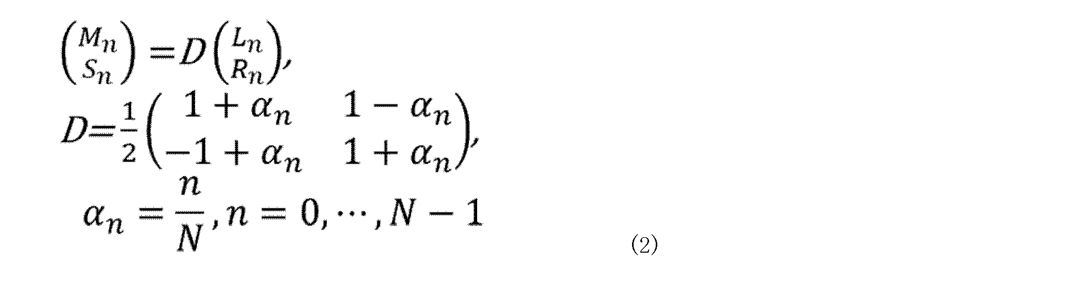
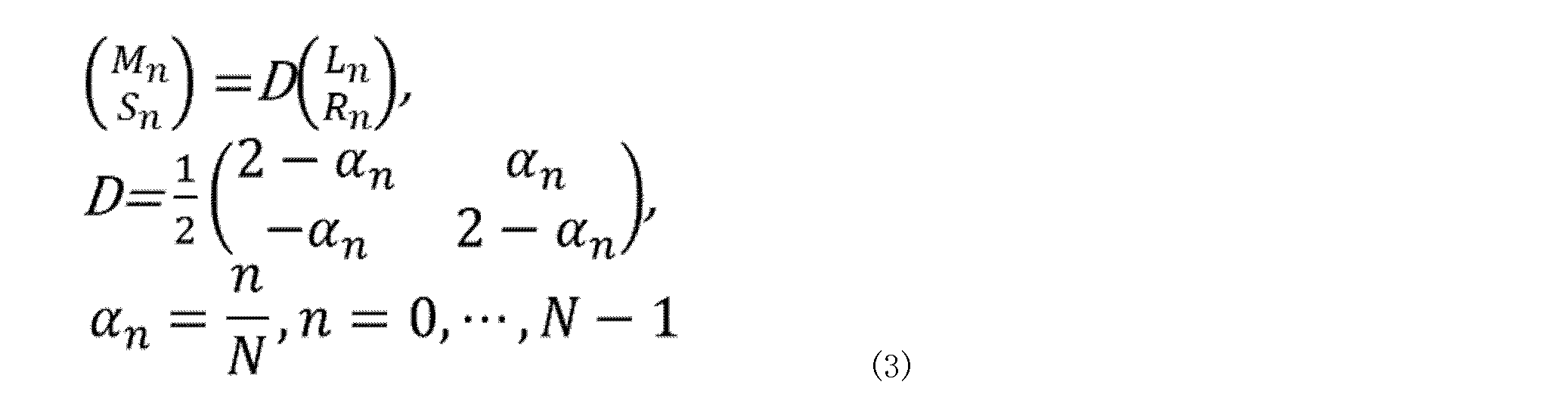
図14は、復号装置(又は、「復号システム」と呼ぶ)20の構成例を示す図である。

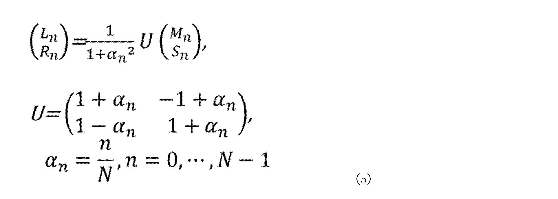

以下、本開示の第2の実施の形態について図面を参照して説明する。第2の実施の形態では、入力信号の主要成分の少なくとも一部が、ステレオTD符号化に用いられているCELP符号化のコア帯域外に存在するかどうかを判定する手段を備え、その結果を符号化モードの切替制御に用いる点において第1の実施の形態と異なる。
1)完全M/S符号化モードと判定される(全周波数帯域においてM/S符号化を用いた方がLR符号化を用いるよりも効率的であると判定される)
2)Midチャネルの符号化に必要とされるビット数の、Midチャネル及びSideチャネルの両チャネルの符号化に必要とされるビット数に対する割合が、所定の範囲内である
3)入力ステレオ信号が音声信号であると判断される(入力ステレオ信号が音声信号の特徴を強く示している)
図15は、第1の実施の形態で説明した図3の構成例に対して、入力ステレオ信号の主要成分が拡張帯域に存在するか否かを判定する、主要帯域判定部109をさらに備えた変換・分析・前処理・符号化制御部11を含む、符号化装置10の別の構成例を示す図である。主要帯域判定部109以外の構成は、図3と共通であるので、説明を省略する。図15において主要帯域判定部109への入力は図示していないが、Lチャンネル(Left channel)信号及びRチャンネル(Right channel)信号を含むステレオ信号が入力されてもよいし、ステレオ信号を入力して何らかの分析を行う分析部が出力する分析結果が入力されてもよい。何れの場合でも、主要帯域判定部109は、入力信号の主要成分の少なくとも一部が(ステレオTD符号化に用いられているCELPベース符号化の)拡張帯域に存在するか否かに関する情報をFD/TD判定部106へ出力する。FD/TD判定部106は、主要帯域判定部109から入力された情報を符号化モードの判定に用いる。主要帯域判定部109は、例えば、周波数変換(例えば、MDCT変換)された入力信号を複数のバンド(帯域)に分割し、各バンドエネルギーを算出し、コア帯域と拡張帯域に含まれるバンドエネルギーの総和に対する、拡張帯域に含まれるバンドエネルギーの総和の比率を算出し、算出された比率が所定の閾値を上回るかどうかで入力信号の主要成分が拡張帯域に存在するか否かを判定する。
図16は、図7の判定手順に、入力信号の主要成分が拡張帯域に存在するか否かを判定するステップ(S29)を最初の処理ステップとして加えた処理フローである。なお、3つの判定ステップ(S21、S28、S29)の順番は限定されないが、特許文献1に示されるようなステレオFD符号化の場合、完全M/S符号化かどうかの判定は常に実施されるので、ステップS21を最初に行えば無駄にステップS28やステップS29を行わなくて済む。
11 変換・分析・前処理・符号化制御部
12 M/S変換部
13 スペクトル符号化部
14 ITD補正部
15 ミキシング部
16 CELPベース符号化部
17 切替多重化部
20 復号装置
21 分離切替部
22 スペクトル復号部
23 逆M/S変換部
24 逆変換部
25 CELPベース復号部
26 逆ミキシング部
27 切替部
101 第1の変換部
102 M/S判定部
103 ITD分析部
104 ITDシフト部
105 第2の変換部
106 FD/TD判定部
107 制御部
108 音声/音楽判定部
109 主要帯域判定部
Claims (9)
- 入力されたステレオ信号がミッド―サイドステレオ方式を用いて符号化するのに適した信号であると判断される場合に、ミッドチャネルの符号化に必要と推定されるビット数とサイドチャネルの符号化に必要と推定されるビット数とを用いて計算される数値に基づいて、第1符号化モードと、第2符号化モードの何れを適用するかを決定する制御部と、
前記第1符号化モードを適用すると決定される場合、前記ミッドチャネルの信号にCode-Excited-Linear-Prediction(CELP)符号化を適用する第1符号化部と、
前記第2符号化モードを適用すると決定される場合、前記ステレオ信号に対して、スペクトル符号化を行う第2符号化部と、
を具備する符号化装置。 - 前記制御部は、
前記数値が第1の閾値以上かつ第2の閾値以下の場合に前記第1符号化モードを適用すると決定し、
前記数値が第1の閾値未満または第2の閾値を超える場合に前記第2符号化モードを適用すると決定する、
請求項1に記載の符号化装置。 - 前記第1符号化モードは、前記CELP符号化を含むマルチモード符号化である、
請求項2記載の符号化装置。 - 前記制御部は、前記ステレオ信号が音声信号であるか否かを判定し、
前記ステレオ信号が音声信号であると判定され、前記数値が第1の閾値以上かつ第2の閾値以下である場合に、前記第1符号化モードを適用すると決定する、
請求項1に記載の符号化装置。 - 前記入力されたステレオ信号が前記ミッド―サイドステレオ方式を用いて符号化するのに適した信号であると判断される場合とは、周波数領域に変換された前記ステレオ信号の周波数スペクトルの複数の帯域の全てにおいて、前記ミッド―サイドステレオ方式を用いると判断された場合である、
請求項1に記載の符号化装置。 - 前記入力されたステレオ信号における左チャンネルと右チャンネルとのチャンネル間時間差を0に近づける補正処理を行う補正部、を更に具備し、
前記第1符号化部は、前記チャンネル間時間差を補正した後の前記ステレオ信号を変換して得られる前記ミッド―サイド信号に対してCELP符号化を行う、
請求項1に記載の符号化装置。 - 前記チャンネル間時間差に対する補正の範囲は、音声信号を再現するための角度の分解能に基づく、
請求項6に記載の符号化装置。 - 前記制御部は、前記第1符号化モードを適用する連続した複数の区間のうち、前記第2符号化モードを適用する区間と隣り合う区間において前記第1符号化モードのModified Discrete Cosine Transform(MDCT)ベースの符号化を行う、
請求項6に記載の符号化装置。 - 符号化装置は、
入力されたステレオ信号がミッド―サイドステレオ方式を用いて符号化するのに適した信号であると判断される場合に、ミッドチャネルの符号化に必要と推定されるビット数とサイドチャネルの符号化に必要と推定されるビット数とを用いて計算される数値に基づいて、第1符号化モードと、第2符号化モードの何れを適用するかを決定し、
前記第1符号化モードを適用すると決定される場合、前記ミッドチャネルの信号にCode-Excited-Linear-Prediction(CELP)符号化を適用し、
前記第2符号化モードを適用すると決定される場合、前記ステレオ信号に対して、スペクトル符号化を行う、
符号化方法。
Priority Applications (2)
| Application Number | Priority Date | Filing Date | Title |
|---|---|---|---|
| JP2024576205A JPWO2024166647A1 (ja) | 2023-02-08 | 2024-01-19 | |
| US19/150,065 US20260045263A1 (en) | 2023-02-08 | 2024-01-19 | Encoding device and encoding method |
Applications Claiming Priority (4)
| Application Number | Priority Date | Filing Date | Title |
|---|---|---|---|
| JP2023017778 | 2023-02-08 | ||
| JP2023-017778 | 2023-02-08 | ||
| JP2023-064797 | 2023-04-12 | ||
| JP2023064797 | 2023-04-12 |
Publications (1)
| Publication Number | Publication Date |
|---|---|
| WO2024166647A1 true WO2024166647A1 (ja) | 2024-08-15 |
Family
ID=92262346
Family Applications (1)
| Application Number | Title | Priority Date | Filing Date |
|---|---|---|---|
| PCT/JP2024/001505 Ceased WO2024166647A1 (ja) | 2023-02-08 | 2024-01-19 | 符号化装置、及び、符号化方法 |
Country Status (3)
| Country | Link |
|---|---|
| US (1) | US20260045263A1 (ja) |
| JP (1) | JPWO2024166647A1 (ja) |
| WO (1) | WO2024166647A1 (ja) |
Citations (1)
| Publication number | Priority date | Publication date | Assignee | Title |
|---|---|---|---|---|
| JP2021119383A (ja) * | 2016-01-22 | 2021-08-12 | フラウンホッファー−ゲゼルシャフト ツァ フェルダールング デァ アンゲヴァンテン フォアシュンク エー.ファオ | 改良されたミッド/サイド決定を持つ包括的なildを持つmdct m/sステレオのための装置および方法 |
-
2024
- 2024-01-19 JP JP2024576205A patent/JPWO2024166647A1/ja active Pending
- 2024-01-19 US US19/150,065 patent/US20260045263A1/en active Pending
- 2024-01-19 WO PCT/JP2024/001505 patent/WO2024166647A1/ja not_active Ceased
Patent Citations (1)
| Publication number | Priority date | Publication date | Assignee | Title |
|---|---|---|---|---|
| JP2021119383A (ja) * | 2016-01-22 | 2021-08-12 | フラウンホッファー−ゲゼルシャフト ツァ フェルダールング デァ アンゲヴァンテン フォアシュンク エー.ファオ | 改良されたミッド/サイド決定を持つ包括的なildを持つmdct m/sステレオのための装置および方法 |
Also Published As
| Publication number | Publication date |
|---|---|
| JPWO2024166647A1 (ja) | 2024-08-15 |
| US20260045263A1 (en) | 2026-02-12 |
Similar Documents
| Publication | Publication Date | Title |
|---|---|---|
| EP1916652B1 (en) | Audio encoder, audio encoding method, and associated computer program | |
| CN101496098B (zh) | 用于以与音频信号相关联的帧修改窗口的系统及方法 | |
| JP4934427B2 (ja) | 音声信号復号化装置及び音声信号符号化装置 | |
| AU2014283180B2 (en) | Method and apparatus for obtaining spectrum coefficients for a replacement frame of an audio signal, audio decoder, audio receiver and system for transmitting audio signals | |
| KR101340233B1 (ko) | 스테레오 부호화 장치, 스테레오 복호 장치 및 스테레오부호화 방법 | |
| RU2495503C2 (ru) | Устройство кодирования звука, устройство декодирования звука, устройство кодирования и декодирования звука и система проведения телеконференций | |
| JP2021140170A (ja) | 無相関化信号の寄与の残差信号ベースの調整を用いたマルチチャンネルオーディオデコーダ、マルチチャンネルオーディオエンコーダ、方法およびコンピュータプログラム | |
| EP2693430B1 (en) | Encoding apparatus and method, and program | |
| JP4498677B2 (ja) | 複数チャネル信号の符号化及び復号化 | |
| US12394423B2 (en) | Time-domain stereo encoding and decoding method and related product | |
| US20080140428A1 (en) | Method and apparatus to encode and/or decode by applying adaptive window size | |
| US20230352034A1 (en) | Encoding and decoding methods, and encoding and decoding apparatuses for stereo signal | |
| WO2009081567A1 (ja) | ステレオ信号変換装置、ステレオ信号逆変換装置およびこれらの方法 | |
| CN109804430B (zh) | 参数音频解码 | |
| JP2008519306A (ja) | 信号の組のエンコード及びデコード | |
| CN102272830B (zh) | 音响信号解码装置及平衡调整方法 | |
| KR20190067825A (ko) | 다수의 오디오 신호들의 디코딩 | |
| JP2021525391A (ja) | ダウンミックス信号及び残差信号を計算するための方法及び装置 | |
| CN110249385B (zh) | 多信道解码 | |
| JP7743444B2 (ja) | 信号処理装置、及び、信号処理方法 | |
| US20260045263A1 (en) | Encoding device and encoding method | |
| WO2023153228A1 (ja) | 符号化装置、及び、符号化方法 | |
| JP2020531912A (ja) | ステレオ信号符号化の間に信号を再構成する方法及び機器 | |
| JP2003223193A (ja) | 変換符号化されたデータの復号方法及び変換符号化されたデータの復号装置 | |
| HK40007489B (en) | Multi channel decoding |
Legal Events
| Date | Code | Title | Description |
|---|---|---|---|
| 121 | Ep: the epo has been informed by wipo that ep was designated in this application |
Ref document number: 24753093 Country of ref document: EP Kind code of ref document: A1 |
|
| ENP | Entry into the national phase |
Ref document number: 2024576205 Country of ref document: JP Kind code of ref document: A |
|
| WWE | Wipo information: entry into national phase |
Ref document number: 2024576205 Country of ref document: JP |
|
| NENP | Non-entry into the national phase |
Ref country code: DE |
|
| 122 | Ep: pct application non-entry in european phase |
Ref document number: 24753093 Country of ref document: EP Kind code of ref document: A1 |