WO2024166640A1 - 作業車両 - Google Patents
作業車両 Download PDFInfo
- Publication number
- WO2024166640A1 WO2024166640A1 PCT/JP2024/001334 JP2024001334W WO2024166640A1 WO 2024166640 A1 WO2024166640 A1 WO 2024166640A1 JP 2024001334 W JP2024001334 W JP 2024001334W WO 2024166640 A1 WO2024166640 A1 WO 2024166640A1
- Authority
- WO
- WIPO (PCT)
- Prior art keywords
- brake
- auto
- running wheels
- work vehicle
- condition
- Prior art date
- Legal status (The legal status is an assumption and is not a legal conclusion. Google has not performed a legal analysis and makes no representation as to the accuracy of the status listed.)
- Ceased
Links
Images


Classifications
-
- B—PERFORMING OPERATIONS; TRANSPORTING
- B60—VEHICLES IN GENERAL
- B60T—VEHICLE BRAKE CONTROL SYSTEMS OR PARTS THEREOF; BRAKE CONTROL SYSTEMS OR PARTS THEREOF, IN GENERAL; ARRANGEMENT OF BRAKING ELEMENTS ON VEHICLES IN GENERAL; PORTABLE DEVICES FOR PREVENTING UNWANTED MOVEMENT OF VEHICLES; VEHICLE MODIFICATIONS TO FACILITATE COOLING OF BRAKES
- B60T7/00—Brake-action initiating means
- B60T7/12—Brake-action initiating means for automatic initiation; for initiation not subject to will of driver or passenger
- B60T7/14—Brake-action initiating means for automatic initiation; for initiation not subject to will of driver or passenger operated upon collapse of driver
-
- B—PERFORMING OPERATIONS; TRANSPORTING
- B60—VEHICLES IN GENERAL
- B60T—VEHICLE BRAKE CONTROL SYSTEMS OR PARTS THEREOF; BRAKE CONTROL SYSTEMS OR PARTS THEREOF, IN GENERAL; ARRANGEMENT OF BRAKING ELEMENTS ON VEHICLES IN GENERAL; PORTABLE DEVICES FOR PREVENTING UNWANTED MOVEMENT OF VEHICLES; VEHICLE MODIFICATIONS TO FACILITATE COOLING OF BRAKES
- B60T13/00—Transmitting braking action from initiating means to ultimate brake actuator with power assistance or drive; Brake systems incorporating such transmitting means, e.g. air-pressure brake systems
- B60T13/10—Transmitting braking action from initiating means to ultimate brake actuator with power assistance or drive; Brake systems incorporating such transmitting means, e.g. air-pressure brake systems with fluid assistance, drive, or release
- B60T13/66—Electrical control in fluid-pressure brake systems
- B60T13/662—Electrical control in fluid-pressure brake systems characterised by specified functions of the control system components
-
- B—PERFORMING OPERATIONS; TRANSPORTING
- B60—VEHICLES IN GENERAL
- B60T—VEHICLE BRAKE CONTROL SYSTEMS OR PARTS THEREOF; BRAKE CONTROL SYSTEMS OR PARTS THEREOF, IN GENERAL; ARRANGEMENT OF BRAKING ELEMENTS ON VEHICLES IN GENERAL; PORTABLE DEVICES FOR PREVENTING UNWANTED MOVEMENT OF VEHICLES; VEHICLE MODIFICATIONS TO FACILITATE COOLING OF BRAKES
- B60T13/00—Transmitting braking action from initiating means to ultimate brake actuator with power assistance or drive; Brake systems incorporating such transmitting means, e.g. air-pressure brake systems
- B60T13/74—Transmitting braking action from initiating means to ultimate brake actuator with power assistance or drive; Brake systems incorporating such transmitting means, e.g. air-pressure brake systems with electrical assistance or drive
- B60T13/746—Transmitting braking action from initiating means to ultimate brake actuator with power assistance or drive; Brake systems incorporating such transmitting means, e.g. air-pressure brake systems with electrical assistance or drive and mechanical transmission of the braking action
-
- B—PERFORMING OPERATIONS; TRANSPORTING
- B60—VEHICLES IN GENERAL
- B60T—VEHICLE BRAKE CONTROL SYSTEMS OR PARTS THEREOF; BRAKE CONTROL SYSTEMS OR PARTS THEREOF, IN GENERAL; ARRANGEMENT OF BRAKING ELEMENTS ON VEHICLES IN GENERAL; PORTABLE DEVICES FOR PREVENTING UNWANTED MOVEMENT OF VEHICLES; VEHICLE MODIFICATIONS TO FACILITATE COOLING OF BRAKES
- B60T7/00—Brake-action initiating means
- B60T7/02—Brake-action initiating means for personal initiation
- B60T7/04—Brake-action initiating means for personal initiation foot actuated
- B60T7/042—Brake-action initiating means for personal initiation foot actuated by electrical means, e.g. using travel or force sensors
-
- B—PERFORMING OPERATIONS; TRANSPORTING
- B60—VEHICLES IN GENERAL
- B60T—VEHICLE BRAKE CONTROL SYSTEMS OR PARTS THEREOF; BRAKE CONTROL SYSTEMS OR PARTS THEREOF, IN GENERAL; ARRANGEMENT OF BRAKING ELEMENTS ON VEHICLES IN GENERAL; PORTABLE DEVICES FOR PREVENTING UNWANTED MOVEMENT OF VEHICLES; VEHICLE MODIFICATIONS TO FACILITATE COOLING OF BRAKES
- B60T2220/00—Monitoring, detecting driver behaviour; Signalling thereof; Counteracting thereof
- B60T2220/06—Adjustment of accelerator pedal reaction forces
-
- B—PERFORMING OPERATIONS; TRANSPORTING
- B60—VEHICLES IN GENERAL
- B60T—VEHICLE BRAKE CONTROL SYSTEMS OR PARTS THEREOF; BRAKE CONTROL SYSTEMS OR PARTS THEREOF, IN GENERAL; ARRANGEMENT OF BRAKING ELEMENTS ON VEHICLES IN GENERAL; PORTABLE DEVICES FOR PREVENTING UNWANTED MOVEMENT OF VEHICLES; VEHICLE MODIFICATIONS TO FACILITATE COOLING OF BRAKES
- B60T2240/00—Monitoring, detecting wheel/tyre behaviour; counteracting thereof
Definitions
- the present invention relates to a work vehicle that performs tasks such as mowing the lawn.
- Patent Document 1 there are known work vehicles equipped with an auto-parking function that applies a braking force to the wheels and applies the brakes to hold the vehicle in place, regardless of whether the worker operates the brake pedal.
- Patent Document 2 there is known a technology that has an auto-parking function that applies a braking force to the wheels by controlling an electric actuator, and automatically releases the brake hold state when certain conditions are met.
- the present invention aims to provide a work vehicle that can solve these problems and improve safety by applying the brakes and holding the vehicle in place at the appropriate time using the auto-parking function.
- the first invention provides: A work vehicle equipped with running wheels and a work implement, A brake mechanism capable of braking the running wheels by operating an electric actuator, and a control device for controlling the operation of the electric actuator,
- the control device is configured to control the electric actuator to enter an auto brake state in which the running wheels are kept braked when an auto brake application condition is satisfied, When an auto brake release condition is satisfied, the braking of the running wheels in the auto brake state is released,
- a seating detection sensor is provided to detect a seating position in the pilot's seat and transmit the detection result to the control device.
- the automatic brake application condition includes a condition that the seating detection sensor changes from a detection state to a non-detection state
- the present invention provides a work vehicle characterized in that the auto brake release condition is configured to include a condition that a seating detection sensor is in a detection state.
- the above invention improves safety by controlling whether the automatic brake is on or off depending on the seating position of the worker. It also prevents the worker from forgetting to apply the brake when leaving the seat, and prevents the work vehicle from rolling downhill if the worker leaves the seat on a slope.
- the second invention is the above-mentioned first invention
- the control device is characterized in that when the seating detection sensor is in a non-detection state for a certain period of time, it is configured to stop the driving motor that rotates the running wheels and the work machine motor that drives the work machine, and then enter the auto brake state.
- the above invention automatically stops the travel motor and the work machine motor, allowing for a safer transition to the auto brake state.
- the third invention is A work vehicle equipped with running wheels and a work implement, A brake mechanism capable of braking the running wheels by operating an electric actuator, and a control device for controlling the operation of the electric actuator,
- the control device is configured to, when an auto-brake application condition is satisfied, enter an auto-brake state in which the running wheels are kept braked by controlling the electric actuator, When an auto brake release condition is satisfied, the braking of the running wheels in the auto brake state is released,
- the work vehicle is characterized in that the auto brake application condition is that the accelerator pedal is released for a certain period of time.
- a fourth aspect of the present invention is the third aspect of the present invention,
- the control device is further connected to a key switch that enables driving of a driving motor that rotates the running wheels, a running wheel rotation speed detection sensor that detects the rotation speed of the running wheels, and an accelerator pedal sensor that detects the depression amount of an accelerator pedal, and is configured to be able to transmit various information;
- the present invention provides a work vehicle characterized in that the auto brake application conditions are that the key switch is in an operating position capable of driving the driving motor, the running wheel rotation speed detection sensor is in a state in which it is not detecting the rotation speed of the running wheels, and the accelerator pedal has been released for a certain period of time.
- the brakes are automatically applied and the vehicle is put into a hold state when the work vehicle is stopped, regardless of the operator's operation, thereby improving safety.
- the fifth invention is A work vehicle equipped with running wheels and a work implement, A brake mechanism capable of braking the running wheels by operating an electric actuator, and a control device for controlling the operation of the electric actuator, the control device is configured to, when an auto-brake application condition is satisfied, establish an auto-brake state in which the running wheels are kept braked by controlling the electric cylinder, When an auto brake release condition is satisfied, the braking of the running wheels in the auto brake state is released,
- the present invention provides a work vehicle characterized in that the autobrake release condition is configured to be a condition that an accelerator pedal is depressed to a level equal to or greater than a dead zone.
- a sixth aspect of the present invention is the fifth aspect of the present invention,
- the control device is further connected to a key switch that drives a driving motor that rotates the driving wheels and an accelerator pedal sensor that detects an amount of depression of an accelerator pedal, and is configured to be able to transmit various information;
- a work vehicle characterized in that the auto brake release condition is configured to be such that the key switch is in an operating position capable of driving the driving motor and the accelerator pedal is depressed beyond the dead zone.
- the auto brake state can be automatically released without the operator's operation, and brake drag due to forgetting to release the brake can be prevented.
- the seventh invention is A work vehicle equipped with running wheels and a work implement, A brake mechanism capable of braking the running wheels by operating an electric actuator, and a control device for controlling the operation of the electric actuator,
- the control device is configured to control the electric actuator to enter an auto brake state in which the running wheels are kept braked when an auto brake application condition is satisfied, When an auto brake release condition is satisfied, the braking of the running wheels in the auto brake state is released,
- an automatic brake application condition is that a brake pedal is depressed for a certain period of time.
- the eighth aspect of the present invention is the seventh aspect of the present invention,
- an automatic brake application condition is that the work vehicle is in a stopped state, the automatic brake is in a released state, and the brake pedal is depressed for a certain period of time.
- the brakes can be automatically put into a hold state by operating the brake pedal, so that convenience can be improved by a quick and simple operation.
- a ninth invention provides a work vehicle according to any one of the first to eighth inventions, characterized in that the work vehicle is equipped with an on-board charger and the absence of a charging signal from the on-board charger is set as a condition for releasing the auto brake.
- the above invention is suitable for improving safety.
- the present invention provides a work vehicle that can improve safety by applying the brakes and holding the vehicle in place at the appropriate time using the auto-parking function.
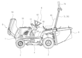
- FIG. 1 is a left side view of a work vehicle.
- FIG. 2 is a left side view of the work vehicle with the bonnet cover in an open position.
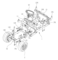
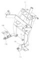
- FIG. 3 is a perspective view of a main portion of the work vehicle with a part cut away.
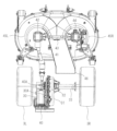
- FIG. 4 is a rear view of the work vehicle.
- FIG. 5 is a plan view of the rear wheels and the main parts of the working machine.
- FIG. 6 is a left side view of the rear wheel and a main portion of the working machine.
- FIG. 7 is a left side view of the electric motor for the rear wheels and the electric motor for the working machine.
- FIG. 8 is a perspective view of the main parts around the steering wheel.
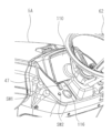
- FIG. 9 is a perspective view of the vehicle body.
- FIG. 10 is a perspective view of the steering post.
- FIG. 10 is a perspective view of the steering post.
- FIG. 11 is a left side view of a main portion of a brake mechanism that controls braking of the running wheels.
- FIG. 12 is a plan view of the main part of a brake mechanism that controls braking of the running wheels.
- FIG. 13 is a perspective view of the main parts around the brake mechanism.
- FIG. 14 is a control block diagram of a controller serving as a control device.
- FIG. 15 is a table showing the automatic brake application conditions of the controller.
- FIG. 16 is a table showing the autobrake release conditions of the controller.
- FIG. 17 is a flowchart showing the control of the controller in the charging mode.
- a pair of left and right front wheels 2 are provided at the front of a traveling body 1 of a working vehicle such as a riding lawnmower, a pair of left and right rear wheels 3 are provided at the rear of the traveling body 1, and a working machine 4 for cutting grass or the like is provided between the front wheels 2 and the rear wheels 3 on the underside of the traveling body 1.
- a bonnet section 5 is provided at the front of the upper side of the traveling body 1, a control section 6 on which an operator rides is provided behind the bonnet section 5, a safety frame (ROPS) 7 for protecting the operator is provided behind the control section 6, and a grass collection container 8 for storing grass cut by the work machine 4 is provided below the safety frame 7.
- ROPS safety frame
- the bonnet section 5 is provided with a battery 50 that stores electricity to be supplied to the travel motor 30 that drives the rear wheels 3, which are the running wheels, and the work machine motor 40 that drives the work machine 4, and the battery 50 is covered by a bonnet cover 5A.
- the bonnet cover 5A is supported by a support shaft (not shown) that extends in the left-right direction and is provided at the front of the traveling body 1. This makes it possible to effectively utilize the space formed in the bonnet section 5 and also suppresses differences in the weight balance in the fore-and-aft direction of the work vehicle.
- a cockpit 60 is provided at the rear of the control section 6, and a steering wheel 62 is provided in front of the cockpit 60.
- the steering wheel 62 is supported on the upper part of a steering shaft 63 that extends in the vertical direction, and the steering shaft 63 is supported by the steering post 11.
- a cleaner lever 65 for operating a cleaner (not shown) that forcibly transports grass clippings remaining in a chute 46 (see FIG. 4) that transports grass clippings cut by the work machine 4 to the grass collection container 8, and a storage case (not shown) for storing a charging cable used when charging the battery 50 is provided behind the cleaner lever 65.
- the work vehicle can be moved to a nearby warehouse or the like without moving the work vehicle to a charging station, and the battery 50 can be charged by connecting a household outlet provided in the warehouse or the like to an on-board charger 80 (hereinafter sometimes referred to as OBC 80) that is a so-called OBC (On Board Charger) (see FIG. 14).
- OBC 80 On Board Charger
- the input voltage of the on-board charger 80 is configured to correspond to an AC voltage of 100 to 240 V.
- a lift lever 66 for raising and lowering the work machine 4 is provided on the right fender 64R of the operator's seat 60.
- a brake pedal 68 is provided to the left of the steering post 11 on the floor 67 of the control unit 6, and forward and reverse accelerator pedals 69 (see Figure 7) are provided to the right.
- an electrical component 61 (hereinafter referred to as the BMS control device 61) that manages the battery management system (BMS) and controls the battery 50. This allows the space formed below the cockpit 60 to be used effectively.
- a seating detection sensor (seat switch) SW3 that can detect the load on the cockpit 60 and thereby detect when an operator is seated.
- the safety frame 7 is formed from a left support portion 7L that extends in the vertical direction, a right support portion 7R that extends in the vertical direction, and an inverted U-shaped connecting portion 7A that connects the upper portions of the left support portion 7L and the right support portion 7R.
- a detachable drink holder 90 is attached to the safety frame 7. In this way, by being able to arrange the drink holder 90 on the safety frame 7, it is convenient because a drink can be held to the side of the cockpit 60.
- a traction motor 30 which is an electric motor such as a synchronous motor or induction motor operated with a three-phase AC voltage waveform that drives the rear wheels 3, is provided below the BMS control device 61.
- the output shaft 30A formed to extend in the left-right direction of the traction motor 30 is connected to the upper part of a gear box 31 that reduces the speed of the output rotation transmitted from the output shaft 30A to increase the output torque or reverse the direction of rotation.
- the traction motor 30 is provided in a position offset toward the left rear wheel 3L from the center in the left-right direction.
- the output rotation that has been accelerated or decelerated by the gear box 31 is transmitted to a drive shaft 33 extending in the left-right direction via a differential gear 32 that is provided at the bottom of the gear box 31 and is formed by a differential gear or the like.
- the output rotation transmitted to the drive shaft 33 is transmitted to the left rear wheel 3L and the right rear wheel 3R that are supported at both ends of the drive shaft 33.
- a work machine motor 40 which is a motor such as a synchronous motor or induction motor operated with a three-phase AC voltage waveform that drives the work machine 4.
- the output shaft 40A of the work machine motor 40 extends in the fore-and-aft direction and is connected to the rear of a universal joint 41 that also extends in the fore-and-aft direction.
- the output shaft 40A is provided above the drive shaft 33 and perpendicular to the drive shaft 33. This allows the space formed below the travel motor 30 to be effectively utilized.
- the transmission path between the work machine motor 40 and the work machine 4 can be shortened, so the output rotation of the work machine motor 40 can be efficiently transmitted to the work machine 4.
- the work machine motor 40 is provided in a position offset toward the left rear wheel 3L from the center in the left-right direction.
- the front part of the universal joint 41 is connected to a gear box 42, which reduces the speed of the output rotation transmitted from the universal joint 41 to increase the output torque.
- the output rotation transmitted to the gear box 42 is transmitted to a left cutting blade (not shown) provided in the left discharge passage 45L of the work machine 4 via an output shaft formed by extending in the vertical direction of the gear box 42.
- a connecting member 43 extending in the left-right direction is connected to the right part of the gearbox 42, and the right part of the connecting member 43 is connected to the gearbox 44.
- the output rotation transmitted to the gearbox 44 is transmitted to a right cutting blade (not shown) provided in the right discharge passage 45R of the work machine 4 via an output shaft formed by extending in the up-down direction of the gearbox 44.
- the output rotation speeds of the output shafts of gearbox 42 and gearbox 44 are the same, but the directions of rotation are opposite; that is, in a plan view, the output shaft of gearbox 42 rotates clockwise, and the output shaft of gearbox 44 rotates counterclockwise.
- the rotation speed of the driving motor 30 can be increased or decreased by using the throttle lever 47 (see Figure 8), which is a power setting device provided on the left side of the steering wheel 62.
- the throttle lever 47 When the throttle lever 47 is in the neutral position, the output rotation of the driving motor 30 becomes zero.
- the throttle lever 47 is moved from the neutral position to the forward tilt position, the output rotation of the driving motor 30 is increased or decreased according to the magnitude of the tilt angle of the forward tilt position.
- the speed change lever is moved from the neutral position to the rearward tilt position, the output rotation of the driving motor 30 is increased or decreased according to the magnitude of the tilt angle of the rearward tilt position, and the rotation direction of the output rotation of the driving motor 30 is reversed.
- the discharge outlets of the left discharge passage 45L and the right discharge passage 45R are connected to the inlet of the chute 46 that transports the cut grass, etc. to the grass collection container 8.
- the discharge outlet of the chute 46 is connected to the inlet of the grass collection container 8.
- the front of the chute 46 is provided to the right of the universal joint 41, the rear of the chute 46 is provided to the right of the gear box 31, and in rear view, the chute 46 and grass collection container 8 are provided between the gear box 31 and the right rear wheel 3R.
- the upper wall of the chute 46 When viewed from the side, the upper wall of the chute 46 is formed with an upward slope toward the rear, and the rear of the chute 46 is provided extending downward below the BMS control device 61. This makes the rear of the chute 46 larger, making it possible to prevent grass and other objects from clogging the inside of the chute 46.
- FIG. 8 is a perspective view of the main parts around the steering wheel 62.
- a liquid crystal display device 110 capable of displaying various information is provided in front of the steering wheel 62.
- a key switch SW1 and a charge switch SW2 are provided to the left of the steering wheel 62.
- the vehicle body 1 is formed from a vehicle body main body 10 that supports the front wheels 2 and rear wheels 3, and a steering post 11 that supports the steering shaft 63.
- the vehicle body 10 is formed with a left front-rear frame 10L and a right front-rear frame 10R that extend in the fore-aft direction, and the lower part of the steering post 11 is formed with a left connecting part 11L and a right connecting part 11R that extend forward.
- the left connecting part 11L is fixed to the left front and rear frame 10L by fastening means such as bolts
- the right connecting part 11R is fixed to the right front and rear frame 10R by fastening means such as bolts, and they are integrated to form the traveling vehicle body 1.
- a left support member 12L is provided at the front of the left front-rear frame 10L, and the connecting portion of the left support member 12L is formed with an upward incline to the left.
- a right support member 12R is provided at the front of the right front-rear frame 10R, and the connecting portion of the right support member 12R is formed with an upward incline to the right.
- the left support member 12L and the right support member 12R are formed from channel steel.
- a left support member 13L is provided in front of the left connecting part 11L, and the connecting part of the left support member 13L is formed with an upward incline to the left.
- a right support member 13R is provided in front of the right connecting part 11R, and the connecting part of the right support member 12R is formed with an upward incline to the right.
- the left support member 13L and the right support member 13R are formed from channel steel.
- the lower part of the steering post 11 is formed with a protrusion 14 that protrudes forward at a predetermined distance in the left-right direction, and a buffer member 15 made of a rubber material or the like is provided at the tip of the protrusion 14.
- the left upper and lower frame 20L extends upward from the rear of the left front and rear frame 10L
- the right upper and lower frame 20R extends upward from the rear of the right front and rear frame 10R
- the upper parts of the left upper and lower frame 20L and the right upper and lower frame 20R are connected to the left and right frame 21 that extends in the left and right direction.
- a left connecting part 22L is provided on the left part of the left-right frame 21, which supports the lower part of the left support part 7L of the safety frame 7, and a right connecting part 22R is provided on the right part of the left-right frame 21, which supports the lower part of the right support part 7R of the safety frame 7.
- Fig. 11 is a left side view of the main part of a brake mechanism BK that controls braking of the running wheels (rear wheels 3)
- Fig. 12 is a plan view of the main part of the same
- Fig. 13 is a perspective view of the main part around the brake mechanism BK. 11 and 12, the brake 70, which applies a brake to the rotation of the rear wheel 3 caused by the output from the gear box 31, is connected to a forward/rearward movement rod 71 that is configured to be able to move forward and backward in response to the operation of the brake pedal 68.
- the brake 70 is configured to be switched between operation and non-operation in response to the pulling operation of the forward/rearward movement rod 71 moving forward and backward.
- an electric cylinder 72 is connected to this forward/reverse rod 71, and when the electric cylinder 71 expands and contracts, the forward/reverse rod 71 advances and retreats forward and backward, regardless of the operation of the brake pedal 68.
- the expansion and contraction of this electric cylinder 72 is controlled by a controller 77 (see FIG. 14), which is a control device.
- the brake pedal 68 rotates counterclockwise on the page about a support shaft 68A extending in the left-right direction, moving the forward/reverse rod 71 forward.
- the brake 70 is actuated, and the rear wheel 3 is braked. In other words, the brake 70 is applied.
- the controller 77 controls the electric cylinder 72 to contract (contracted state)
- the forward/reverse rod 71 is moved forward. This activates the brake 70 and brakes the rear wheel 3.
- the electric cylinder 71 is maintained in a contracted state, making it possible to achieve a hold state with the brake 70 applied.
- the controller 77 controls the electric cylinder 71 to expand (extended state)
- the forward/reverse rod 71 is moved rearward. This releases the operation of the brake 70.
- the rear wheel 3 is released from braking and the hold state is released.
- the rear of the electric cylinder 72 is connected to the forward/reverse rod 71 via a connecting member 73 extending in the left/right direction.
- the rear of the electric cylinder 72 is rotatably fixed to a cylindrical pin 73A formed on the left part of the connecting member 73.
- the front part of the piston side of the electric cylinder 72 is connected to a fixed member 77 erected on the upper surface of the traveling body 1 via a cylindrical pin 74C extending in the left-right direction of the attachment/detachment device 74.
- the front part of the electric cylinder 72 is fixed to the pin 74C so as to be freely rotatable.
- the attachment/detachment device 74 is made up of a support plate 74A erected on the top surface of the traveling body 1, a roughly U-shaped (case-like with three sides) support body 74B extending leftward from the left surface of the support plate 74A, a pin 74C extending left and right inside the support body 74B, and a handle 74D attached to the left of the pin 74C.
- the handle 74D By operating the handle 74D, the electric cylinder 72 can be attached and detached to the traveling body 1.
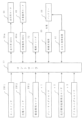
- FIG. 14 is a control block diagram of the controller 77 which is a control device.
- the controller 77 is a so-called VCU (Vehicle Control Unit), and includes an electronic control device ECU (Electronic Control Unit) to enable various controls.
- VCU Vehicle Control Unit
- ECU Electronic Control Unit
- the input side of the controller 77 is connected to a key switch SW1, a charging switch SW2, a seating detection sensor SW3, a brake pedal sensor s1, a running wheel rotation speed detection sensor s2, and an accelerator pedal sensor s3, and the controller 77 is able to acquire information detected by these sensors.
- the controller 77 is also connected to the traveling MDU (30 m), the work machine MDU (40 m), the electric cylinder 72, the on-board charger 80, and the BMS control device 61, and is capable of sending and receiving various information to and from these connected devices.
- the key switch SW1 can be rotated to one of three operating positions: OFF, ACC, or ON.
- the controller 77 is supplied with the current required to maintain the minimum functionality.
- the information processing device such as the CPU of the controller 77 maintains operation and is configured to determine the operating position of the key switch SW1 and perform the minimum necessary processing.
- the driving motor 30 and the work machine motor 40 are not supplied with the power required to drive them.
- the controller 77 When the key switch SW1 is in the ACC position, the controller 77 receives the power required for normal operation, and the LCD display device 110 and other devices are activated. On the other hand, the driving motor 30 and the work machine motor 40 are not receiving the power required for driving, so even if the accelerator pedal 69 is depressed, for example, the rear wheels 3 do not rotate and the work vehicle does not start moving.
- the driving motor 30 and the work equipment motor 40 are supplied with the power necessary for driving, and the rear wheels 3 and the work equipment 4 of the work vehicle are in a state in which they can be driven, making it possible for the vehicle to be driven for work.
- the charging switch SW2 is configured as a momentary switch that can be turned on and off, and when it is in the on state, charging of the battery 50 is possible from an external power source.
- the controller 77 executes the charging mode described below.
- the controller 77 can also obtain information on whether the driver is seated in the driver's seat 60 using the seating detection sensor SW3, the amount of depression of the brake pedal 68 using the brake pedal sensor s1, the rotation speed of the rear wheels 3 (the running wheels) using the running wheel rotation speed detection sensor s2, and the amount of depression of the accelerator pedal 69 using the accelerator pedal sensor s3. These sensors are provided in appropriate positions on the work vehicle.
- the driving MDU (30m) is an inverter control device, and is equipped with an inverter function that controls the rotation speed of the driving motor 30, and a simple CPU (relay circuit for the inverter) that controls this.
- MDU is an abbreviation for motor drive unit.
- the driving MDU (40m) controls the on/off of the driving motor 30 by controlling the inverter rotation speed, and also functions to output an activation signal for the simple brake of the driving motor 30 when the inverter rotation is turned off. Also, the power to the simple CPU of the inverter of the driving MDU (30m) is turned on and off by turning on and off the MDU signal relay.
- the work machine MDU (40m) is an inverter control device, just like the traveling MDU (30m), and is equipped with an inverter function that controls the rotation speed of the work machine motor 40 and a simple CPU (relay circuit for the inverter) that controls this.
- the work machine MDU (40m) controls the on/off of the work machine motor 40 by controlling the inverter rotation speed, and also functions to output an activation signal for the simple brake of the work machine motor 40 when the inverter rotation is turned off. Also, the power to the simple CPU of the inverter of the work machine MDU (40m) is turned on and off by turning on and off the MDU signal relay.
- the BMS control device 61 is a control device that performs the function of controlling the battery 50, and in particular, controls the power supply from the battery 50 by controlling the on/off of a relay in a battery control circuit (not shown).
- the controller 77 is configured to be able to control the extension and retraction of the electric cylinder 72 by sending a contraction signal to the electric cylinder 72 to command it to contract and an extension signal to command it to extend, and is also able to obtain a feedback signal that indicates the extension and retraction state of the electric cylinder 72.
- the controller 77 configured as described above has an auto-parking function that controls the extension and retraction of the electric cylinder 72 under predetermined conditions to automatically brake or release the brake on the rear wheels 3, which are the traveling wheels.
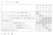
- FIG. 15 is a table showing the automatic brake application conditions of the controller 77.
- the controller 77 controls the extension of the electric cylinder 72 and sets the conditions shown in a list in FIG. 15 as conditions for automatically braking the rear wheels 3 (hereinafter referred to as "auto brake application conditions"). That is, the work vehicle is configured to automatically apply the brakes and enter a hold state (auto brake state) when any of conditions A to E shown in FIG. 15 is satisfied. At this time, the brake pedal 68 is fixed in the depressed position. In addition, when the auto brake state is activated, the liquid crystal display device 110 notifies the user by means of lighting an icon or the like.
- Condition A When the key switch SW1 is turned off (to the OFF position), the work vehicle is in a stopped state (that is, the running wheel rotation speed detection sensor s2 is not detecting the rotation of the running wheels. Alternatively, the vehicle may be considered stopped when the detection value is 10 rpm or less.) With this configuration, when the power to the work vehicle is turned off (that is, the key switch SW1 is turned off), the running wheels are automatically braked, which prevents the driver from forgetting to apply the brakes when parking and improves safety.
- Condition C The conditions are that the key switch SW1 is in the ON position or ACC position, the work vehicle is stopped, the auto brake is released, and the brake pedal 68 is depressed for a certain period of time (e.g., one second). With this configuration, the brakes can be automatically put into a hold state by operating the brake pedal 68, improving convenience through quick and simple operation. Note that if the key switch SW1 is configured not to have an ACC position, the condition can be that the key switch SW1 is in the ON position instead of the ACC position.
- Condition D The conditions are that the key switch SW1 is in the ON position or ACC position, the work vehicle is stopped, the auto brake is released, and the accelerator pedal 69 has been released for a certain period of time (e.g., 1 second). With this configuration, if the accelerator pedal 69 is released for a certain period of time without the operation of the worker, the brakes are automatically applied and put into a hold state when the work vehicle is stopped, improving safety. Note that if the key switch SW1 is configured not to have an ACC position, the condition can be that the key switch SW1 is in the ON position instead of the ACC position.
- Condition E The conditions are that the key switch SW1 is in the ON position or the ACC position, the work vehicle is stopped, the auto brake is released, and the work vehicle is in an abnormal stop state (a state in which an abnormality is detected by an abnormality detection sensor, not shown). With this configuration, the brakes are automatically applied and the vehicle is put into a hold state in the event of an abnormality, improving safety. Note that if the key switch SW1 is configured not to have an ACC position, the condition can be that the key switch SW1 is in the ON position instead of the ACC position.
- the controller 77 can be configured to automatically apply the automatic brake when the operator leaves the driver's seat 60, that is, when the seating detection sensor SW3 goes from a detection state to a non-detection state. This prevents the operator from forgetting to apply the brake when the operator leaves the seat, and also prevents the work vehicle from rolling down even if the operator leaves the seat on a slope, thereby improving safety.
- the controller 77 detects the operator's leaving the seat by the seating detection sensor SW3, if the operator has been away from the seat for a certain period of time (for example, several consecutive seconds), it is more preferable from the viewpoint of safety to stop the traveling motor 30 and the working machine motor 40 and to apply the automatic brake at the timing when the traveling motor 30 stops.
- the safety can be further improved by configuring the working machine motor 40 not to restart unless the PTO switch (not shown) is returned to OFF and then turned ON again.
- FIG. 16 is a table showing the automatic brake release conditions of the controller 77.
- the auto brake release condition refers to a condition for automatically releasing the auto brake state, and when any of the conditions F to K shown in Figure 16 is satisfied, the controller 77 of the work vehicle controls the contraction of the electric cylinder 72 to release the braking of the rear wheel 3, which is the running wheel.
- Condition F The conditions are that the key switch SW1 is in the ON position or the ACC position, there is no charging signal (a signal indicating that charging is in progress) from the in-vehicle charger 80, the seat detection sensor SW3 detects a seat, the vehicle is in the auto brake state, and the accelerator pedal 69 is depressed beyond the dead zone.
- the auto brake state can be automatically released without the operator's operation, and dragging of the brake due to forgetting to release the brake can be prevented.
- safety can be improved by not releasing the brake when there is a charging signal from the in-vehicle charger 80. This is because it is dangerous to drive with the charging cord plugged in.
- the condition is that the seat detection sensor SW3 detects a seat
- safety can be further improved by allowing the release when the operator is in the seat.
- the accelerator pedal 69 is configured to include a forward pedal and a reverse pedal, it is preferable that the condition be that either pedal depression is equal to or greater than the dead zone.
- the key switch SW1 is configured not to have an ACC position, the condition can be that the key switch SW1 is in the ON position instead of the ACC position.
- FIG. 17 is a flowchart showing the control of the controller 77 in the charging mode. As shown in FIG. 17, the control of the controller 77 in the charging mode is configured as follows.
- the charging mode is started by pressing the charging switch SW2. This improves safety because charging will not start unless the switch is pressed.
- the charging switch SW2 is a momentary switch, and the charging mode course can be selected by how the switch is pressed. The specified time in the figure is, for example, three seconds. If the charging switch SW3 is pressed while the power to the work machine 4 is OFF, a charging mode flag is set in the controller 77, and the charging mode is maintained even if the charging switch SW2 is not continuously pressed. During charging mode, a charging switch lamp (not shown) is lit so that the operator can distinguish. If the charging switch SW2 is pressed during charging mode, the charging mode flag is turned off and the charging mode is terminated.
- the charging mode has a full charge course and a supplementary charge course, and the selected course is determined by the pressing time of the charging switch SW2.
- the supplementary charge course is configured so that the battery 50 is not fully charged, but is only charged up to a specified battery remaining capacity. In other words, once the battery is charged to a specified remaining capacity, the charging mode flag is cleared and the charging mode is terminated. This prevents deterioration of the battery 50.
- the full charge course once the battery 50 is fully charged, the charging mode flag is cleared and the charging mode is terminated.
- a buzzer or other means is sounded to notify the operator so that the supplementary charge course can be distinguished from the full charge course.
Landscapes
- Engineering & Computer Science (AREA)
- Transportation (AREA)
- Mechanical Engineering (AREA)
- Electric Propulsion And Braking For Vehicles (AREA)
- Braking Systems And Boosters (AREA)
- Regulating Braking Force (AREA)
Priority Applications (3)
| Application Number | Priority Date | Filing Date | Title |
|---|---|---|---|
| EP24753086.8A EP4663492A1 (en) | 2023-02-06 | 2024-01-18 | Work vehicle |
| CN202480008432.9A CN120569316A (zh) | 2023-02-06 | 2024-01-18 | 作业车辆 |
| US19/290,919 US20250360896A1 (en) | 2023-02-06 | 2025-08-05 | Work vehicle |
Applications Claiming Priority (2)
| Application Number | Priority Date | Filing Date | Title |
|---|---|---|---|
| JP2023015937A JP2024111430A (ja) | 2023-02-06 | 2023-02-06 | 作業車両 |
| JP2023-015937 | 2023-02-06 |
Related Child Applications (1)
| Application Number | Title | Priority Date | Filing Date |
|---|---|---|---|
| US19/290,919 Continuation US20250360896A1 (en) | 2023-02-06 | 2025-08-05 | Work vehicle |
Publications (1)
| Publication Number | Publication Date |
|---|---|
| WO2024166640A1 true WO2024166640A1 (ja) | 2024-08-15 |
Family
ID=92262348
Family Applications (1)
| Application Number | Title | Priority Date | Filing Date |
|---|---|---|---|
| PCT/JP2024/001334 Ceased WO2024166640A1 (ja) | 2023-02-06 | 2024-01-18 | 作業車両 |
Country Status (5)
| Country | Link |
|---|---|
| US (1) | US20250360896A1 (https=) |
| EP (1) | EP4663492A1 (https=) |
| JP (1) | JP2024111430A (https=) |
| CN (1) | CN120569316A (https=) |
| WO (1) | WO2024166640A1 (https=) |
Families Citing this family (1)
| Publication number | Priority date | Publication date | Assignee | Title |
|---|---|---|---|---|
| WO2026048260A1 (ja) * | 2024-08-29 | 2026-03-05 | 株式会社デンソー | 制御装置、農業機械、建設機械、制御方法、及び制御プログラム |
Citations (6)
| Publication number | Priority date | Publication date | Assignee | Title |
|---|---|---|---|---|
| US6135230A (en) * | 1998-10-09 | 2000-10-24 | Caterpillar S.A.R.L. | Interlock control system for a work machine |
| JP2010179872A (ja) * | 2009-02-09 | 2010-08-19 | Mazda Motor Corp | 車両の走行制御装置 |
| JP2012162192A (ja) * | 2011-02-08 | 2012-08-30 | Honda Motor Co Ltd | 電動パーキングブレーキ装置 |
| WO2018025290A1 (ja) | 2016-08-02 | 2018-02-08 | マツダ株式会社 | 車両の制御装置 |
| JP2019123307A (ja) * | 2018-01-15 | 2019-07-25 | 三菱自動車工業株式会社 | ブレーキシステム |
| JP2021102978A (ja) | 2019-12-25 | 2021-07-15 | 井関農機株式会社 | 作業車両 |
-
2023
- 2023-02-06 JP JP2023015937A patent/JP2024111430A/ja active Pending
-
2024
- 2024-01-18 EP EP24753086.8A patent/EP4663492A1/en active Pending
- 2024-01-18 CN CN202480008432.9A patent/CN120569316A/zh active Pending
- 2024-01-18 WO PCT/JP2024/001334 patent/WO2024166640A1/ja not_active Ceased
-
2025
- 2025-08-05 US US19/290,919 patent/US20250360896A1/en active Pending
Patent Citations (6)
| Publication number | Priority date | Publication date | Assignee | Title |
|---|---|---|---|---|
| US6135230A (en) * | 1998-10-09 | 2000-10-24 | Caterpillar S.A.R.L. | Interlock control system for a work machine |
| JP2010179872A (ja) * | 2009-02-09 | 2010-08-19 | Mazda Motor Corp | 車両の走行制御装置 |
| JP2012162192A (ja) * | 2011-02-08 | 2012-08-30 | Honda Motor Co Ltd | 電動パーキングブレーキ装置 |
| WO2018025290A1 (ja) | 2016-08-02 | 2018-02-08 | マツダ株式会社 | 車両の制御装置 |
| JP2019123307A (ja) * | 2018-01-15 | 2019-07-25 | 三菱自動車工業株式会社 | ブレーキシステム |
| JP2021102978A (ja) | 2019-12-25 | 2021-07-15 | 井関農機株式会社 | 作業車両 |
Also Published As
| Publication number | Publication date |
|---|---|
| JP2024111430A (ja) | 2024-08-19 |
| EP4663492A1 (en) | 2025-12-17 |
| US20250360896A1 (en) | 2025-11-27 |
| CN120569316A (zh) | 2025-08-29 |
Similar Documents
| Publication | Publication Date | Title |
|---|---|---|
| EP2110295B1 (en) | Electric ground working vehicle | |
| JP7065747B2 (ja) | 草刈機 | |
| US8657041B2 (en) | Control system for a lawnmower vehicle having a plurality of electric motors | |
| JP7694643B2 (ja) | 作業車両 | |
| JP5836033B2 (ja) | トラクタの作業動力取り出し構造 | |
| JPH09202221A (ja) | 車両のブレーキ制御装置 | |
| JP2021049828A (ja) | 作業車 | |
| EP4426576A1 (en) | Vehicle controller, vehicle including a vehicle controller, and method of operating a vehicle | |
| US20250360896A1 (en) | Work vehicle | |
| CN104254455A (zh) | 用于多用途运载车的前部动力输出装置 | |
| JP2004350475A (ja) | 作業車両の伝動装置 | |
| JP2013126383A (ja) | 草刈機 | |
| JP2024111430A5 (https=) | ||
| JP5776221B2 (ja) | 作業車両 | |
| JP6628616B2 (ja) | プラグインハイブリッド作業車 | |
| JP2025159145A (ja) | 作業車両 | |
| JP6735698B2 (ja) | 作業車 | |
| JP2022092241A (ja) | 作業機械、作業機械の制御装置、および作業機械の制御方法 | |
| JP2015104936A (ja) | トラクタ | |
| JP5708005B2 (ja) | 作業車両 | |
| TWI822660B (zh) | 用於兩輪車輛的停車輔助系統以及其的控制方法 | |
| JP2023178907A (ja) | 電動作業車両の制御システム | |
| JP2009083612A (ja) | 作業車 | |
| JP7235629B2 (ja) | 作業車 | |
| US20240016081A1 (en) | Control system for work vehicle |
Legal Events
| Date | Code | Title | Description |
|---|---|---|---|
| 121 | Ep: the epo has been informed by wipo that ep was designated in this application |
Ref document number: 24753086 Country of ref document: EP Kind code of ref document: A1 |
|
| WWE | Wipo information: entry into national phase |
Ref document number: 202480008432.9 Country of ref document: CN |
|
| WWP | Wipo information: published in national office |
Ref document number: 202480008432.9 Country of ref document: CN |
|
| NENP | Non-entry into the national phase |
Ref country code: DE |
|
| WWP | Wipo information: published in national office |
Ref document number: 2024753086 Country of ref document: EP |