WO2024166455A1 - ライン設計装置、ライン設計プログラムおよびライン設計方法 - Google Patents
ライン設計装置、ライン設計プログラムおよびライン設計方法 Download PDFInfo
- Publication number
- WO2024166455A1 WO2024166455A1 PCT/JP2023/039013 JP2023039013W WO2024166455A1 WO 2024166455 A1 WO2024166455 A1 WO 2024166455A1 JP 2023039013 W JP2023039013 W JP 2023039013W WO 2024166455 A1 WO2024166455 A1 WO 2024166455A1
- Authority
- WO
- WIPO (PCT)
- Prior art keywords
- information
- production
- environmental load
- amount
- line
- Prior art date
- Legal status (The legal status is an assumption and is not a legal conclusion. Google has not performed a legal analysis and makes no representation as to the accuracy of the status listed.)
- Ceased
Links
Images









Classifications
-
- G—PHYSICS
- G05—CONTROLLING; REGULATING
- G05B—CONTROL OR REGULATING SYSTEMS IN GENERAL; FUNCTIONAL ELEMENTS OF SUCH SYSTEMS; MONITORING OR TESTING ARRANGEMENTS FOR SUCH SYSTEMS OR ELEMENTS
- G05B19/00—Program-control systems
- G05B19/02—Program-control systems electric
- G05B19/418—Total factory control, i.e. centrally controlling a plurality of machines, e.g. direct or distributed numerical control [DNC], flexible manufacturing systems [FMS], integrated manufacturing systems [IMS] or computer integrated manufacturing [CIM]
-
- G—PHYSICS
- G06—COMPUTING OR CALCULATING; COUNTING
- G06Q—INFORMATION AND COMMUNICATION TECHNOLOGY [ICT] SPECIALLY ADAPTED FOR ADMINISTRATIVE, COMMERCIAL, FINANCIAL, MANAGERIAL OR SUPERVISORY PURPOSES; SYSTEMS OR METHODS SPECIALLY ADAPTED FOR ADMINISTRATIVE, COMMERCIAL, FINANCIAL, MANAGERIAL OR SUPERVISORY PURPOSES, NOT OTHERWISE PROVIDED FOR
- G06Q10/00—Administration; Management
- G06Q10/06—Resources, workflows, human or project management; Enterprise or organisation planning; Enterprise or organisation modelling
- G06Q10/063—Operations research, analysis or management
-
- G—PHYSICS
- G06—COMPUTING OR CALCULATING; COUNTING
- G06Q—INFORMATION AND COMMUNICATION TECHNOLOGY [ICT] SPECIALLY ADAPTED FOR ADMINISTRATIVE, COMMERCIAL, FINANCIAL, MANAGERIAL OR SUPERVISORY PURPOSES; SYSTEMS OR METHODS SPECIALLY ADAPTED FOR ADMINISTRATIVE, COMMERCIAL, FINANCIAL, MANAGERIAL OR SUPERVISORY PURPOSES, NOT OTHERWISE PROVIDED FOR
- G06Q50/00—Information and communication technology [ICT] specially adapted for implementation of business processes of specific business sectors, e.g. utilities or tourism
- G06Q50/04—Manufacturing
Definitions
- the present invention relates to a line design device, a line design program, and a line design method.
- the present invention claims priority to Japanese Patent Application No. 2023-015774 filed on February 6, 2023, and the contents of that application are incorporated by reference into this application in designated countries where incorporation by reference to literature is permitted.
- the introduction of a production line that constitutes the manufacturing process of a product involves phases such as inquiries, design, hardware production, software creation, installation testing, and delivery. Of these, in the design phase, productivity design (identification of process types and processes to be handed over to external organizations), line configuration (identification and allocation of production resources), and basic production plans (specific operations taking into account operating hours) must be finalized.
- Patent Document 1 states that the production line simulation device includes: a production management data storage unit that stores production management data in which input material data on materials input to a process and output material data on materials output from a process are recorded for each process required from the start to the end of the production of a product; a parameter storage unit that stores equipment parameters including information on the production capacity of the machines used in each process or the work in each process, and logistics equipment parameters including information on the performance of logistics equipment that transports materials between each process; a layout sheet storage unit that stores a layout sheet that defines the physical positional relationship between each process; a layer storage unit that stores a layer that defines the transport route of the logistics equipment between each process; a calculation unit that calculates the operating time and standby time of the equipment and the logistics equipment when producing a product by referring to the production management data, the equipment parameters, and the logistics equipment parameters in a production line consisting of multiple processes defined by the layout sheet and the layer; and an emission calculation unit that calculates the amount of carbon dioxide emitted by the equipment and the logistics equipment while producing a product by
- Patent Document 1 predicts carbon dioxide emissions by calculating equipment operating times based on the equipment layout when designing a production line, and calculates the predicted amount of carbon dioxide emissions from the entire factory, but does not have the functionality to reduce carbon dioxide emissions.
- the objective of this invention is to achieve a reduction in greenhouse gas emissions when designing a production line.
- the present application includes multiple means for solving at least some of the above problems, examples of which are as follows:
- One aspect of the present invention is a line design device comprising: a storage unit that stores production volume information including information on the timing and amount of a product to be produced; and production resource candidate specification information including specification information of resource candidates to be used in the production of the product; a production plan calculation unit that calculates production plan information for the product using the resource candidates so as to satisfy the production volume information; an environmental load evaluation unit that evaluates the environmental load associated with the production of the product using the production plan information; and an output unit that outputs line configuration information using the resource candidates according to the environmental load.
- the present invention provides technology that enables reductions in greenhouse gas emissions when designing production lines.
- FIG. 1 illustrates an example of a configuration of a line design device.
- FIG. 13 is a diagram illustrating an example of a data structure of production volume information.
- 13 is a diagram illustrating an example of a data structure of outsourcing candidate specification information.
- 11 is a diagram illustrating an example of a data structure of production resource candidate specification information.
- FIG. 11 is a diagram illustrating an example of a data structure of power supply form specification information.
- FIG. 4 is a diagram illustrating an example of a data structure of process information.
- FIG. 13 is a diagram illustrating an example of a data structure of in-house production/outsourcing information.
- 11 is a diagram illustrating an example of a data structure of line configuration information.
- FIG. 2 is a diagram illustrating an example of a data structure of production plan information.
- FIG. 1 illustrates an example of a configuration of a line design device.
- FIG. 13 is a diagram illustrating an example of a data structure of production volume information.
- 13 is a
- FIG. 13 is a diagram illustrating an example of a flowchart of a production line process.
- FIG. 13 is a diagram illustrating an example of a flowchart of a line design plan calculation process.
- FIG. 13 is a diagram illustrating an example of a flowchart of a productivity design plan generation process.
- FIG. 13 is a diagram illustrating an example of a flowchart of a line configuration plan generation process.
- FIG. 13 is a diagram illustrating an example of a flowchart of a production plan generation process.
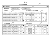
- FIG. 13 is a diagram showing an example of a line design result screen.
- FIG. 13 is a diagram showing an example of a Pareto solution display screen.
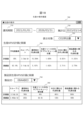
- FIG. 13 is a diagram showing an example of a production KPI display screen.
- the terms “input unit”, “output unit”, “display unit” and “interface device” may refer to one or more interface devices.
- the one or more interface devices may be at least one of the following: One or more I/O (Input/Output) interface devices.
- the I/O (Input/Output) interface devices are interface devices to at least one of the I/O devices and a remote display computer.
- the I/O interface device to the display computer may be a communications interface device.
- the at least one I/O device may be a user interface device, for example, either an input device such as a keyboard and a pointing device, or an output device such as a display device.
- One or more communication interface devices may be any communication interface devices.
- the one or more communication interface devices may be one or more homogeneous communication interface devices (e.g., one or more NICs (Network Interface Cards)) or two or more heterogeneous communication interface devices (e.g., a NIC and an HBA (Host Bus Adapter)).
- NICs Network Interface Cards
- HBA Home Bus Adapter
- memory refers to one or more memory devices, which are an example of one or more storage devices, and may typically be a primary storage device. At least one memory device in the memory may be a volatile memory device or a non-volatile memory device.
- a “persistent storage device” may be one or more persistent storage devices, which are an example of one or more storage devices.
- a persistent storage device may typically be a non-volatile storage device (e.g., an auxiliary storage device), and specifically may be, for example, a hard disk drive (HDD), a solid state drive (SSD), a non-volatile memory express (NVME) drive, or a storage class memory (SCM).
- HDD hard disk drive
- SSD solid state drive
- NVME non-volatile memory express
- SCM storage class memory
- a “storage unit” or a “storage device” may refer to either a memory or a persistent storage device, or both.
- a "processing unit” or a “processor” may be one or more processor devices.
- At least one processor device may typically be a microprocessor device such as a CPU (Central Processing Unit), but may also be other types of processor devices such as a GPU (Graphics Processing Unit).
- At least one processor device may be single-core or multi-core.
- At least one processor device may be a processor core.
- At least one processor device may be a broad processor device such as a circuit that is a collection of gate arrays written in a hardware description language that performs some or all of the processing (e.g., an FPGA (Field-Programmable Gate Array), a CPLD (Complex Programmable Logic Device), or an ASIC (Application Specific Integrated Circuit)).
- FPGA Field-Programmable Gate Array
- CPLD Complex Programmable Logic Device
- ASIC Application Specific Integrated Circuit
- yyy unit functions are sometimes described using the expression "yyy unit", but the functions may be realized by one or more computer programs being executed by a processor, or by one or more hardware circuits (e.g., FPGAs or ASICs), or by a combination of these.
- a function When a function is realized by a program being executed by a processor, the function may be at least a part of the processor, since the specified processing is performed using a storage device and/or an interface device, etc., as appropriate. Processing described with a function as the subject may be processing performed by a processor or a device having the processor.
- a program may be installed from a program source.
- the program source may be, for example, a program distribution computer or a computer-readable recording medium (e.g., a non-transitory recording medium).
- the description of each function is an example, and multiple functions may be combined into one function, or one function may be divided into multiple functions.
- processing may be explained using a "program” or a “processing unit” as the subject, but processing explained using a program as the subject may also be processing performed by a processor or a device having that processor.
- two or more programs may be realized as one program, and one program may be realized as two or more programs.
- information that produces an output for an input may be described using expressions such as "xxx information", but the information may be any type of data structure, or may be a neural network that generates an output for an input, or a trained model such as a genetic algorithm or random forest.
- the data structure of each piece of information is an example, and one data structure may be divided into two or more data structures, or all or part of two or more data structures may be one data structure.
- a “system” may be a system made up of one or more physical computers, or may be a system (e.g., a cloud computing system) realized on a group of physical computing resources (e.g., a cloud infrastructure).
- the line design device When the line design device "displays" the display information, it may mean displaying the display information on a display device possessed by the computer, or the computer may send the display information to a display computer (in the latter case, the display information is displayed by the display computer).
- Example 1 In this example, it is assumed that the line configuration is designed when starting up a new production line, and the line design device 100 supports both the productivity design that is the premise for the design of the line configuration and the production plan that is the premise for the line configuration. Specifically, the line design device 100 integrates each design stage and each design to optimize greenhouse gas emissions and throughput.
- Main equipment is equipment that performs work that creates added value.
- main equipment includes machine tools, injection molding machines, inspection equipment, etc.
- Setup equipment is equipment that performs setup work that does not create added value, such as the attachment and detachment of workpieces to and from main equipment, and the transport of workpieces between main equipment.
- setup equipment includes industrial robots, gantry loaders, and unmanned guided vehicles with robotic arms.
- Peripheral equipment is equipment that is required for main equipment or setup equipment to perform work.
- peripheral equipment includes material stockers, conveyors, floor running rails, overhead running rails, etc.
- one or more processes are defined to complete the production of one product. All processes are assigned to one main equipment, and multiple processes may be assigned to one main equipment.
- FIG. 1 is a diagram showing an example of the configuration of a line design device.
- the line design device 100 is provided at the manufacturing site (area) or in a facility outside the manufacturing site.
- the line design device 100 is capable of communicating with an external device 200 that can be treated as a group of devices according to the usage environment, such as a display computer, which is communicatively connected via a network N.
- the network N may be, for example, a LAN (Local Area Network), a WAN (Wide Area Network), a VPN (Virtual Private Network), a communication network that uses general public lines such as the Internet in part or in whole, a mobile phone communication network, or a combination of these.
- the network N may also be a wireless communication network such as Wi-Fi (registered trademark) or 5G (Generation).
- the line design device 100 has a processing unit 110, a storage unit 120, an input unit 140, an output unit 150, and a communication unit 160.
- the input unit 140 is displayed and operated on a screen, for example, and receives input information operated and entered using a keyboard or mouse.
- the output unit 150 is a type of processing unit that performs presentation processing on the information to be displayed on the output screen, outputs the information to the screen, and also performs screen control for operational inputs on the screen, such as scrolling, sorting, and highlighting.
- the communication unit 160 communicates with a group of devices corresponding to the usage environment, such as a display computer, that are communicatively connected via the network N.
- the memory unit 120 includes product design information 121, production volume information 122, outsourcing candidate specification information 123, production resource candidate specification information 124, power supply form specification information 125, process information 126, in-house production/outsourcing information 127, line configuration information 128, production plan information 129, and production performance information 130.
- Product design information 121 is information that identifies the parts that make up the product to be produced.
- Product design information 121 is, for example, a BOM (Bill of Materials) and various modeling data.
- Production quantity information 122 is information that includes information on the timing and amount of the product to be produced.
- Outsourcing candidate specification information 123 is information that includes candidates for external organizations that will be responsible for part of the manufacturing process and their environmental assessments.
- the production resource candidate specification information 124 is information that includes specification information of the resource candidate used in the production of a product.
- the resource candidate specification information includes the introduction cost of the resource candidate, the greenhouse gas emissions generated when the resource is introduced (manufacturing, relocating, etc.), and the greenhouse gas emissions generated when the resource is in operation.
- the power supply form specification information 125 is information that specifies the type of energy source for each time period and the environmental load associated with power consumption.
- the product design information 121, production volume information 122, outsourcing candidate specification information 123, production resource candidate specification information 124, and power supply form specification information 125 are mainly used as input information.
- Process information 126 is information in which a process type (information that specifies the type of work performed in a process, such as cutting, forging, welding, assembly, etc.) is assigned to each process.
- In-house production/outsourcing information 127 is information in which a part of a manufacturing process, for example each process, is assigned as to whether or not an external organization (e.g., a processing company) will be asked to take charge of the process (sometimes referred to as "outsourcing"), and, if outsourcing, the external organization in charge is assigned.
- Line configuration information 128 is information that assigns resource candidates to take charge of a process when outsourcing is not performed (sometimes called "in-house production").
- Production plan information 129 is information that assigns resource candidates or external outsourced organizations to take charge of each production process of a product, and identifies the operation dates and times.
- Production performance information 130 is information that records the actual operation of the production line in accordance with the production plan information.
- FIG. 2 is a diagram showing an example of the data structure of production volume information.
- a monthly production volume 122b is associated with each product ID 122a that identifies a product.
- FIG. 3 is a diagram showing an example of the data structure of outsourcing candidate specification information.
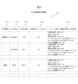
- the outsourcing candidate specification information 123 a process type 123a, a subcontractor ID 123b, a subcontractor name 123c, a production capacity (lead time) 123d, and a greenhouse gas emission amount per 10 tons of work 123e are stored in association with each other.
- the process type 123a is information that specifies the type of work performed in a process, such as cutting, forging, welding, assembly, etc.
- the outsourcer ID 123b and the outsourcer name 123c are information that identifies the external organization to which the outsourcer is to be provided and the name of that organization.
- the production capacity (lead time) 123d is information that indicates the production capacity of the external organization to which the outsourcer is to be provided using the lead time.
- the greenhouse gas emissions per 10 t (tons) of work 123e is information that identifies the amount of greenhouse gases emitted in the production of the external organization to which the outsourcer is to be provided.
- the greenhouse gas emission amount 123e per 10 t (tons) of work includes the amount of greenhouse gas emitted during the movement, installation, processing, and movement of products to and from subcontractors, for each type of greenhouse gas.
- the greenhouse gas includes various gases that are considered to have a greenhouse effect, and representative ones include carbon dioxide (CO 2 ), methane (CH 4 ), nitrous oxide (N 2 O), hydrofluorocarbons (HFCs), perfluorocarbons (PFCs), and sulfur hexafluoride (SF 6 ), but is not limited to these, and does not necessarily have to include these and may be any of them, or the greenhouse effect may be converted to any of the gases.
- FIG. 4 is a diagram showing an example of the data structure of production resource candidate specification information.
- equipment major classification 124a process type 124b
- equipment name 124c equipment name 124c
- purchase price 124d power consumption 124e
- supply chain discharge amount 124f supply chain discharge amount
- the equipment major classification 124a is information that identifies the equipment classification of the production resource.
- the process type 124b is information that identifies the type of work or role performed in the process, such as cutting, forging, welding, assembly, machine setup, and material storage.
- the equipment name 124c is information that identifies the resource candidate.
- the purchase price 124d is information that identifies the monetary cost associated with purchasing the resource candidate.
- the power consumption 124e is information that identifies the amount of power consumed when the resource candidate is operated.
- the supply chain emissions 124f is information that identifies the amount of greenhouse gases emitted by each type of greenhouse gas during the manufacture, transportation, installation, and other introduction and disposal of the resource candidate.
- the types of greenhouse gases are the same as those in the outsourcing candidate specification information 123.
- FIG. 5 is a diagram showing an example of the data structure of the power supply form specification information.
- the power supply form specification information 125 stores, for each time period 125a, the type of power 125b, the amount of greenhouse gas emissions per unit 125c, and the unit price 125d in association with each other.
- Time zone 125a is information that specifies a time zone that is set without overlap.
- Power type 125b is information that specifies the type of power in the time zone specified by time zone 125a.
- the type of power is the type of energy source that generates the power.
- Types of energy sources include, for example, fossil energy such as “thermal power” and renewable energy such as “solar power.”
- renewable energies include, for example, “solar power,” “wind power,” “hydropower,” “wave/tidal power,” “flowing water/tides,” “geothermal power,” “solar heat,” “heat in the atmosphere and other heat present in nature,” and “biomass (organic matter derived from plants and animals that can be used as an energy source).”
- renewable energy can refer to all energy that originates from solar, geophysical, or biological sources and is replenished by nature at a rate faster than it can be utilized.
- Greenhouse gas emissions per unit 125c and unit price 125d are information that respectively identifies the amount of greenhouse gases emitted per unit of a given amount of electricity used and the electricity fee.
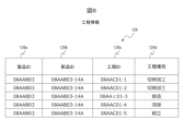
- FIG. 6 is a diagram showing an example of the data structure of process information.
- Process information 126 includes a product ID 126a, a part ID 126b, a process ID 126c, and a process type 126d.
- Product ID 126a is information that identifies the product.
- Part ID 126b is information that identifies the part that constitutes the product.
- Process ID 126c is information that identifies the processing process for the part.
- Process type 126d is information that identifies the type of work (cutting, forging, welding, assembly, etc.) that is adopted (assigned) to the process identified by process ID 126c. For example, for a process that can be created by either cutting or forging, the result of the decision on which to adopt is stored in process type 126d.
- FIG. 7 is a diagram showing an example of the data structure of in-house production/outsourcing information.
- In-house production/outsourcing information 127 includes product ID 127a, part ID 127b, process ID 127c, resource ID 127d, in-house production/outsourcing 127e, and outsourcing destination 127f.
- Product ID 127a is information that identifies the product.
- Part ID 127b is information that identifies the parts that make up the product.
- Process ID 127c is information that identifies the processing process for the parts.
- Resource ID 127d is information that identifies a resource candidate that will be in charge of the process identified by process ID 127c.
- In-house production/outsourcing 127e is information that is the result of a decision as to whether or not to outsource the process identified by process ID 127c.
- Outsourcing destination 127f is information that identifies the external organization to which the product is to be outsourced when in-house production/outsourcing 127e includes information to the effect of outsourcing.
- FIG. 8 is a diagram showing an example of the data structure of line configuration information.
- Line configuration information 128 is information that indicates the design results of a line.
- Line configuration information 128 includes at least the identification of the resources that make up the line and the process for which the resources are responsible. Specifically, line configuration information 128 includes product ID 128a, part ID 128b, process ID 128c, and resource ID 128d.
- Product ID 128a is information that identifies a product.
- Part ID 128b is information that identifies a part that makes up a product.
- Process ID 128c is information that identifies the processing process for the part.
- Resource ID 128d is information that identifies the resource in charge of the process identified by process ID 128c.
- the production plan information 129 includes a product ID 129a, a part ID 129b, a process ID 129c, a resource ID 129d, a date and time 129e, a start time 129f, an end time 129g, a power type 129h, and a CO2 emission prediction 129j.
- the product ID 129a is information that identifies a product.
- the part ID 129b is information that identifies a part that constitutes the product.
- the process ID 129c is information that identifies a processing process for the part.
- the resource ID 129d is information that identifies a resource that is in charge of the process identified by the process ID 129c.
- the date and time 129e is information specifying the date and time to carry out the process specified by the process ID 129c.
- the start time 129f and the end time 129g are information specifying the start time and end time of the process specified by the process ID 129c.
- the power type 129h is information specifying the energy source of the power used in the process specified by the process ID 129c.
- the CO2 emission prediction 129j is information specifying the amount of greenhouse gas emissions predicted to be emitted in the process specified by the process ID 129c (in FIG. 9 , CO2 is shown as an example of the greenhouse gas, but this is not limited to this, and some or all of other greenhouse gases may be included, or the amount converted to CO2 may be included).
- the processing unit 110 includes a process sequence calculation unit 111, a manufacturing method calculation unit 112, an in-house production/outsourcing selection unit 113, a line configuration calculation unit 114, a production plan calculation unit 115, an iterative improvement unit 116, an environmental load assessment unit 117, a KPI (Key Performance Indicator) display unit 118, and a main control unit 119.
- the process sequence calculation unit 111 is an existing technology that reads the product design information 121 and calculates the processes and their sequence.
- the manufacturing method calculation unit 112 selects the method for each manufacturing process based on the environmental load.
- the in-house production/outsourcing selection unit 113 selects the construction method for each manufacturing process based on the environmental load calculated by the environmental load assessment unit 117 and determines whether to outsource the manufacturing process to an external organization.
- the line configuration calculation unit 114 outputs line configuration information that uses resource candidates from the production resource candidate specification information 124 according to the environmental load amount.
- the production plan calculation unit 115 calculates the product production plan information 129 using the resource candidates in the production resource candidate specification information 124 so as to satisfy the production quantity information 122.
- the production plan calculation unit 115 calculates the production plan information 129 so as to reduce the environmental load (e.g., greenhouse gas emissions).
- the production plan calculation unit 115 also calculates the production plan information 129 by prioritizing the use of renewable energy sources. In particular, the production plan calculation unit 115 calculates the production plan information 129 by prioritizing the use of electricity generated by sunlight as a renewable energy source.
- the iterative improvement unit 116 continually changes the production plan information 129 and the line configuration information 128 until at least the improvement rate of the environmental load amount converges.
- the environmental load assessment unit 117 assesses the environmental load associated with the production of the product using the production plan information 129 calculated by the production plan calculation unit 115. Specifically, the environmental load assessment unit 117 identifies an energy source according to the operating time zone of the resource candidates included in the production plan information 129, and calculates the environmental load. In particular, the environmental load assessment unit 117 may calculate the amount of greenhouse gas (e.g., carbon dioxide including the equivalent) emissions associated with the production of the product, and calculate this as the environmental load of the manufacturing process.
- greenhouse gas e.g., carbon dioxide including the equivalent
- the environmental load assessment unit 117 also calculates the environmental load using outsourcing candidate specification information 123, product design information 121, and candidate manufacturing process information including candidate manufacturing processes for the product. Specifically, the environmental load assessment unit 117 calculates the amount of greenhouse gas emissions for each candidate manufacturing process, and calculates the amount of greenhouse gas emissions when the manufacturing process is outsourced to an external organization using the candidate outsourcing specification information 123, and calculates this as the environmental load of the manufacturing process. The environmental load assessment unit 117 also collects the operation records of candidate resources to be installed in the production line installed based on the line configuration information 128, calculates the actual amount of environmental load, and calculates the environmental load and the actual amount of environmental load for each product.
- the KPI display unit 118 generates a screen that displays the forecast and actual results of KPIs, such as planned values, actual values, design proposals, and environmental loads, calculated by various processes related to production line design. For example, the KPI display unit 118 generates screens such as a line design result screen, a Pareto solution display screen, and a production KPI display screen, which will be described later, and displays them on the output unit 150.
- KPIs such as planned values, actual values, design proposals, and environmental loads
- the main control unit 119 performs the process of calculating the line design proposal.
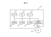
- FIG. 10 is a diagram showing an example of the hardware configuration of a line design device.
- the line design device 100 can be realized as a general computer 300 equipped with a processor 301, memory 302, storage 303 such as a hard disk drive (HDD), a storage medium read/write device 305 that reads or writes information to a portable storage medium 304 such as a CD (Compact Disk) or a DVD (Digital Versatile Disk), an input device 306 such as a keyboard, mouse, or barcode reader, an output device 307 such as a display, and a communication device 308 that communicates with other computers via a communication network such as the Internet, or as a network system equipped with a plurality of such computers 300.
- a communication network such as the Internet, or as a network system equipped with a plurality of such computers 300.
- the process sequence calculation unit 111, the manufacturing method calculation unit 112, the in-house production/outsourcing selection unit 113, the line configuration calculation unit 114, the production plan calculation unit 115, the iterative improvement unit 116, the environmental load assessment unit 117, the KPI display unit 118, and the main control unit 119 can be realized by loading a specific program stored in the storage 303 into the memory 302 and executing it with the processor 301, the input unit 140 and the output unit 150 can be realized by the processor 301 using the input device 306 and the output device 307, and the memory unit 120 can be realized by the processor 301 using the memory 302 or the storage 303.
- This specific program may be downloaded to storage 303 from storage medium 304 via storage medium read/write device 305, or from a network via communication device 308, and then loaded onto memory 302 and executed by processor 301.
- the predetermined program may also be loaded directly onto memory 302 from storage medium 304 via storage medium read/write device 305, or from a network via communication device 308, and executed by processor 301.
- Communication unit 160 can be realized by processor 301, memory 302, and communication device 308.
- the line design device 100 may be a wearable computer that can be worn by a worker, such as a headset, goggles, glasses, or an intercom.
- FIG. 11 is a diagram showing an example of the flow of production line processing.
- Production line processing includes not only the design of the production line configuration but also processing related to the formulation of a production plan. Production line processing starts when a start command is received from a user via an interface device.
- the main control unit 119 performs a line design proposal calculation process (step S001). Details will be described later, but the line design proposal calculation process is a process in which the product design information 121 is used to perform productivity design, line configuration design, and production planning, and optimization.
- the main control unit 119 determines whether or not the time for creating a production plan has arrived (step S002). Specifically, the main control unit 119 acquires date and time information and determines whether or not a specific time for creating a production plan has arrived (e.g., the weekend, the end of the month, etc.). If the time for creating a production plan has not arrived ("No" in step S002), the main control unit 119 advances control to step S004.
- a specific time for creating a production plan e.g., the weekend, the end of the month, etc.
- step S003 the production plan creation process is a process that uses the line configuration information 128 to create a production plan that is a Pareto optimal solution for environmental load, cost, and throughput.
- the environmental load assessment unit 117 acquires the production results (step S004). Specifically, the environmental load assessment unit 117 collects the operation results (e.g., power consumption) for resource candidates to be installed in the production line that is set up based on the line configuration information 128, calculates the environmental load results, and calculates the environmental load and the environmental load results for each product. The calculated production results are stored in the production result information 130.
- the operation results e.g., power consumption
- the KPI display unit 118 displays the forecast and actual results of the KPIs (step S005). Specifically, the KPI display unit 118 generates a screen that displays the forecast and actual results of KPIs such as planned values, actual values, design proposals, and environmental loads calculated by various processes related to the production line design. For example, the KPI display unit 118 generates screens such as a line design result screen, a Pareto solution display screen, and a production KPI display screen, which will be described later, and displays them on the output unit 150.
- step S006 determines whether the end of the line operation has arrived. Specifically, the main control unit 119 acquires date and time information and determines whether the specified end of the line operation has arrived. If the end of the line operation has not arrived ("No" in step S006), the main control unit 119 returns control to step S002.
- step S006 If the end of line operation has arrived (Yes in step S006), the main control unit 119 ends the production line processing.
- the above is an example of the flow of production line processing.
- the line is designed, and when the planning period arrives, a production plan is created and the forecast and actual results of KPIs are displayed.
- FIG. 12 is a diagram showing an example of a flowchart for the line design plan calculation process.
- the line design plan calculation process starts in step S001 of the production line process.
- the process sequence calculation unit 111 calculates the process sequence (step S101). Specifically, the process sequence calculation unit 111 reads the product design information 121, analyzes the geometric constraint relationships of the product's components using a predetermined algorithm, and calculates the process sequence.
- the manufacturing method calculation unit 112 and the in-house production/outsourcing selection unit 113 perform a productivity design plan generation process (step S102). Details will be described later, but the productivity design plan generation process is a process that identifies in-house production/outsourcing for each process using the process sequence of the product, etc.
- the line configuration calculation unit 114 performs a line configuration plan generation process (step S103). Details will be described later, but the line configuration plan generation process is a process that uses the product design information 121 and the process sequence of the product, etc., to identify production resources (line configuration information 128) for each process to be produced in-house so as to achieve a Pareto optimal solution for environmental load, cost, and throughput.
- the production plan calculation unit 115 performs a production plan proposal generation process (step S104).
- the production plan proposal generation process is a process for creating a production plan that is a Pareto optimal solution for environmental load, cost, and throughput using the line configuration information 128, as will be described in detail later.
- the iterative improvement unit 116 evaluates the productivity design plan, line configuration plan, and production plan (step S105). Specifically, the iterative improvement unit 116 calculates the cost, throughput, and environmental load for the productivity design plan, line configuration plan, and production plan output in steps S102 to S104.
- the iterative improvement unit 116 updates the optimal plan (step S106). Specifically, the iterative improvement unit 116 updates the productivity plan, line configuration plan, and production plan output in steps S102 to S104 as provisional optimal plans.
- the iterative improvement unit 116 determines whether the improvement rate of the KPI of the updated optimal plan has not converged (step S107). Specifically, the iterative improvement unit 116 determines that the improvement rate of the KPI of the updated optimal plan has not converged if it is equal to or greater than a predetermined threshold (e.g., 0.1%). If the improvement rate of the KPI of the updated optimal plan has not converged (if "Yes" in step S107), the iterative improvement unit 116 returns control to step S103 and re-executes some of the processes with some changes to the resources used.
- a predetermined threshold e.g., 0.15%
- the iterative improvement unit 116 causes the output unit 150 to output the cost, throughput, and environmental load for the optimal line configuration plan and production plan (step S108).
- the above is an example of the flow of the line design proposal calculation process.
- the line design proposal calculation process allows you to perform productivity design, line configuration design, and production planning, and then optimize the process.
- FIG. 13 is a diagram showing an example of a flowchart of the productivity design plan generation process.
- the productivity design plan generation process starts in step S102 of the line design plan calculation process.
- the manufacturing method calculation unit 112 acquires the process sequence of the product (step S201). Specifically, the manufacturing method calculation unit 112 acquires the process sequence of the product calculated in step S101 of the line design proposal calculation process.
- the manufacturing method calculation unit 112 evaluates the greenhouse gas emissions, manufacturing costs, and throughput when the process is carried out based on the candidate manufacturing process information for each process (step S202). Specifically, the manufacturing method calculation unit 112 accepts candidate manufacturing process information for each process via the input unit 140, and estimates the greenhouse gas emissions, manufacturing costs, and throughput for the accepted process. At that time, the manufacturing method calculation unit 112 also accepts input of the target parts and the estimated work time required for that method for each process, and calculates the greenhouse gas emissions, manufacturing costs, and throughput according to the estimated work time.
- the in-house production/outsourcing selection unit 113 uses the manufacturing process candidate information and the outsourcing candidate specification information 123 to evaluate the greenhouse gas emissions, manufacturing costs, and throughput of the outsourcing partner for each process (step S203). Specifically, the in-house production/outsourcing selection unit 113 estimates the greenhouse gas emissions, manufacturing costs, and throughput in the case of outsourcing for each outsourcing partner that can handle the process according to the process type.
- the in-house production/outsourcing selection unit 113 determines in-house production/outsourcing using a multi-objective mathematical optimization method so as to optimize greenhouse gas emissions, manufacturing costs, and throughput (step S204). Specifically, the in-house production/outsourcing selection unit 113 determines in-house production/outsourcing using a multi-objective mathematical optimization method so as to minimize greenhouse gas emissions and manufacturing costs and maximize throughput. In this case, the in-house production/outsourcing selection unit 113 determines in-house production/outsourcing so as to achieve a minimum value using, as the objective function, a composite function obtained by applying predetermined weights to a derived function of greenhouse gas emissions, a derived function of manufacturing costs, and a derived function of throughput with the sign reversed.
- the productivity design plan generation process makes it possible to determine whether to in-house produce or outsource a process in order to optimize greenhouse gas emissions, manufacturing costs, and throughput.
- FIG. 14 is a diagram showing an example of a flowchart of the line configuration plan generation process.
- the line configuration plan generation process starts in step S103 of the line design plan calculation process.
- the line configuration calculation unit 114 uses the production resource candidate specification information 124 and the process sequence to extract a set Rsp of production resources that can realize each process p of the product s (step S301).
- the line configuration calculation unit 114 obtains a taboo list, which is a combination of production resources generated during the search process for the production line processing (step S302).
- the line configuration calculation unit 114 selects the best production resource from the set Rsp of production resources by excluding the combinations of production resources in the taboo list (step S303).
- the line configuration calculation unit 114 uses a multi-objective mathematical optimization method that minimizes the resource cost of the line configuration, the power consumption per unit time of the process, and the supply chain greenhouse gas emissions as evaluation indices.
- the line configuration calculation unit 114 may also randomly change any of the in-house processes to outsourcing and select the best production resource. In this case, the line configuration calculation unit 114 may apply heuristic rules so as not to select an outsourcer in a distant location.
- the line configuration calculation unit 114 adds the non-optimal combination of production resources to the taboo list (step S304).
- the above is an example of the flow of the line configuration plan generation process.
- the line configuration plan generation process makes it possible to determine the production resources for in-house processes so as to optimize resource costs, electricity consumption of the process, and greenhouse gas emissions.
- FIG. 15 is a diagram showing an example of a flowchart of the production plan generation process.
- the production plan generation process begins in step S104 of the line design plan calculation process and in step S003 of the production line processing.
- the production plan generation process can be executed not only when the production line is designed, but also in the operation phase after the production line starts operating.
- production plans can be continuously drawn up to achieve a high production volume and low power consumption from fossil energy sources, thereby contributing to the sustainability of society.
- the production plan calculation unit 115 obtains the work time Trsp for the process determined by the line configuration (production resource r, product s, process p) (step S401).
- the production plan calculation unit 115 uses the work time Trsp to estimate the power consumption Wersp according to the power supply source e (power type) during the work time period (step S402).
- the production plan calculation unit 115 selects the work date and time for production resource r to carry out process p using a multi-objective mathematical optimization method that maximizes the number of products produced, maximizes the amount of electricity consumption derived from renewable energy (for example, “photovoltaic power,” “wind power,” “hydropower,” “wave power/tidal power,” “running water/tides,” “geothermal power,” “solar heat,” “heat in the atmosphere and other heat existing in nature,” “biomass,” etc.), and minimizes the amount of electricity consumption derived from fossil energy (step S403).
- the production plan calculation unit 115 reflects the selected work date and time in the production plan information 129.
- the above is an example of the flow of the production plan generation process.
- the production plan generation process makes it possible to determine a production plan that will produce a high number of units and consume less electricity from fossil energy sources.
- the production plan generation process makes it possible to create a production plan that prioritizes time periods when electricity with a low environmental impact, such as solar power generation, is used.
- FIG. 16 is a diagram showing an example of a line design result screen.
- the line design result screen 500 is an example of a screen displayed in step S108 of the line design proposal calculation process.
- the line design result screen 500 includes an operation period display area 510, a process information display area 520, an in-house/outsourced production (subcontracting) determination and subcontractor information display area 530, a line configuration information display area 540, and a production plan information display area 550.
- the process information display area 520 displays information from the process information 126. In other words, the process type is displayed for each process.
- In-house/outsourced (subcontracted) determination and subcontractor information display area 530 displays information from in-house/outsourced information 127. In other words, whether each process is in-house or outsourced, and if outsourced, the subcontractor, are displayed.
- the line configuration information display area 540 displays information from the line configuration information 128. In other words, it displays the resources used for each process.
- the production plan information display area 550 information from the production plan information 129 is displayed. That is, the resources used for each process, the start time and end time of the process, the type of electricity, and the amount of greenhouse gas emissions are displayed.
- FIG. 17 is a diagram showing an example of a Pareto solution display screen.
- the Pareto solution display screen 600 is an example of a screen displayed in step S108 of the line design plan calculation process.
- the Pareto solution display screen 600 includes a display target KPI specification reception area 610 and a KPI Pareto solution display area 620.
- the display target KPI specification reception area 610 accepts the specification of the axis of the graph to be displayed in the KPI Pareto solution display area 620.
- KPI Pareto solution display area 620 a graph is drawn using the axes accepted in the display target KPI specification acceptance area 610. This graph is plotted for each line design proposal, and the Pareto optimal solution and the candidate solutions are displayed in a distinguishable manner.
- FIG. 18 is a diagram showing an example of a production KPI display screen.
- the production KPI display screen 700 is an example of a screen displayed in step S005 of the production line processing.
- the production KPI display screen 700 includes an operation period display area 710, an aggregation date display area 720, a display target greenhouse gas specification reception area 730, a production KPI plan and results display area 740 for the entire line, a product specification reception area 750, and a product-specific production KPI plan and results display area 760.
- the display target greenhouse gas specification reception area 730 receives the specification of the type of greenhouse gas to be displayed as a production KPI.
- the area 740 displaying the planned and actual production KPIs for the entire line displays the planned and actual production KPIs for the entire line.
- Production KPIs include, for example, average operating rate, throughput, greenhouse gas emissions during operation, supply chain emissions of production resources (greenhouse gas emissions when resources are introduced), greenhouse gas emissions at subcontractors, greenhouse gas emissions related to parts procurement, etc.
- the product specification reception area 750 accepts the specification of the product to be displayed as a production KPI.
- the planned and actual production KPI display area 760 for each product displays the planned and actual production KPI values for each product received in the product designation reception area 750.
- the line design can be performed taking into account greenhouse gas emissions.
- the optimal process and line design proposal can be derived in a short time by taking into account the production plan, and the reduction of greenhouse gas emissions can be achieved by considering the entire operation cycle when designing the production line.
- the present invention is not limited to the above-described embodiments, but includes various modified examples.
- the above-described embodiments have been described in detail to clearly explain the present invention, and are not necessarily limited to those having all of the configurations described. It is also possible to replace part of the configuration of one embodiment with the configuration of another embodiment, and it is also possible to add the configuration of another embodiment to the configuration of one embodiment. It is also possible to add, delete, or replace part of the configuration of each embodiment with other configurations.
- the above-mentioned configurations, functions, processing units, processing means, etc. may be realized in part or in whole in hardware, for example by designing them as integrated circuits. Furthermore, the above-mentioned configurations, functions, etc. may be realized in software by a processor interpreting and executing a program that realizes each function. Information on the programs, tables, files, etc. that realize each function can be stored in a memory, a recording device such as a hard disk or SSD, or a recording medium such as an IC card, SD card, or DVD.
- control lines and information lines shown are those considered necessary for the explanation, and do not necessarily show all control lines and information lines on the product. In reality, it can be assumed that almost all components are interconnected.
Landscapes
- Engineering & Computer Science (AREA)
- Business, Economics & Management (AREA)
- Human Resources & Organizations (AREA)
- Economics (AREA)
- Physics & Mathematics (AREA)
- General Physics & Mathematics (AREA)
- Strategic Management (AREA)
- Quality & Reliability (AREA)
- Manufacturing & Machinery (AREA)
- Theoretical Computer Science (AREA)
- General Business, Economics & Management (AREA)
- Entrepreneurship & Innovation (AREA)
- Marketing (AREA)
- Tourism & Hospitality (AREA)
- Automation & Control Theory (AREA)
- Primary Health Care (AREA)
- General Health & Medical Sciences (AREA)
- Health & Medical Sciences (AREA)
- Development Economics (AREA)
- Educational Administration (AREA)
- General Engineering & Computer Science (AREA)
- Game Theory and Decision Science (AREA)
- Operations Research (AREA)
- Management, Administration, Business Operations System, And Electronic Commerce (AREA)
- General Factory Administration (AREA)
Abstract
生産ラインの設計時に温室効果ガス排出量の削減を実現させる。 ライン設計装置であって、製品を生産すべき時期および量の情報を含む生産物量情報と、製品の生産に用いるリソース候補の仕様情報を含む生産リソース候補仕様情報と、を記憶する記憶部と、生産物量情報を満たすように、リソース候補を用いて製品の生産計画情報を算出する生産計画算出部と、生産計画情報を用いて製品の生産に係る環境負荷量を評価する環境負荷評価部と、環境負荷量に応じて、リソース候補を用いるライン構成情報を出力する出力部と、を備える。
Description
本発明は、ライン設計装置、ライン設計プログラムおよびライン設計方法に関する。本発明は2023年2月6日に出願された日本国特許の出願番号2023-015774の優先権を主張し、文献の参照による織り込みが認められる指定国については、その出願に記載された内容は参照により本出願に織り込まれる。
製品の製造プロセスを構成する生産ラインの導入には、引合、設計、ハードウェア製作、ソフトウェア作成、据付テスト、納入等のフェーズがある。このうち、設計フェーズでは生産性設計(工程種別、外部組織への移譲工程の特定)、ライン構成(生産リソースの特定と配置)、基本的な生産計画(稼働時間を考慮した具体的な運用)等を確定しなければならない。
また、近年では、地球温暖化防止の観点からカーボンニュートラルの実現に向け、製造プロセスの構成および実施においても、環境負荷の低減が要請されている。そのため、環境負荷に対して配慮がなされた生産ラインが導入されることが望ましい。
特許文献1には、「製品の生産開始から終了までに要する工程毎に、工程に投入する素材に関する投入素材データと工程から排出される素材に関する排出素材データとが記録された生産管理データを保持する生産管理データ保持部と、各工程で使用される機械または各工程における作業の生産能力に関する情報を含む装備パラメータと、各工程間で素材を搬送する物流装備の性能に関する情報を含む物流装備パラメータとを保持するパラメータ保持部と、各工程間の物理的な位置関係が定義されたレイアウトシートを保持するレイアウトシート保持部と、各工程間での前記物流装備の搬送ルートが定義されたレイヤを保持するレイヤ保持部と、前記レイアウトシートと前記レイヤによって定義された複数の工程からなる生産ラインにおいて、前記生産管理データ、前記装備パラメータおよび前記物流装備パラメータを参照して、製品を生産するときの前記装備と前記物流装備の稼働時間と待機時間を算出する演算部と、予め設定された単位時間当たりの二酸化炭素排出量と前記稼働時間および前記待機時間とを掛け合わせることで、製品を生産する間に前記装備および前記物流装備によって排出される二酸化炭素量を算出する排出量算出部と、を備えることを特徴とする生産ラインシミュレーション装置」と記載されている。
上述の特許文献1に記載の技術では、生産ライン設計時において、設備レイアウトをベースとして設備の稼働時間を求めて二酸化炭素排出量を予測し、工場全体から排出される二酸化炭素排出量予測を算出する一方で、二酸化炭素排出量を削減するための機能は有していない。
本発明の目的は、生産ラインの設計時に温室効果ガス排出量の削減を実現させることを目的とする。
本願は、上記課題の少なくとも一部を解決する手段を複数含んでいるが、その例を挙げるならば、以下のとおりである。
本発明の一態様は、ライン設計装置であって、製品を生産すべき時期および量の情報を含む生産物量情報と、前記製品の生産に用いるリソース候補の仕様情報を含む生産リソース候補仕様情報と、を記憶する記憶部と、前記生産物量情報を満たすように、前記リソース候補を用いて前記製品の生産計画情報を算出する生産計画算出部と、前記生産計画情報を用いて前記製品の生産に係る環境負荷量を評価する環境負荷評価部と、前記環境負荷量に応じて、前記リソース候補を用いるライン構成情報を出力する出力部と、を備えることを特徴とする。
本発明によれば、生産ラインの設計時に温室効果ガス排出量の削減を実現させる技術を提供することができる。
上記した以外の課題、構成及び効果は、以下の実施形態の説明により明らかにされる。
以下の実施形態においては便宜上その必要があるときは、複数のセクションまたは実施の形態に分割して説明するが、特に明示した場合を除き、それらはお互いに無関係なものではなく、一方は他方の一部または全部の変形例、詳細、補足説明等の関係にある。
また、以下の実施形態において、要素の数等(個数、数値、量、範囲等を含む)に言及する場合、特に明示した場合および原理的に明らかに特定の数に限定される場合等を除き、その特定の数に限定されるものではなく、特定の数以上でも以下でもよい。
さらに、以下の実施形態において、その構成要素(要素ステップ等も含む)は、特に明示した場合および原理的に明らかに必須であると考えられる場合等を除き、必ずしも必須のものではないことは言うまでもない。
同様に、以下の実施形態において、構成要素等の形状、位置関係等に言及するときは特に明示した場合および原理的に明らかにそうではないと考えられる場合等を除き、実質的にその形状等に近似または類似するもの等を含むものとする。このことは、上記数値および範囲についても同様である。
また、実施形態を説明するための全図において、同一の部材には原則として同一の符号を付し、その繰り返しの説明は省略する。ただし、同一の部材であっても環境変更等により変更前の部材と称呼を共有すると混乱を生ぜしめるおそれが高い場合、別の異なる符号や名称を付すことがある。以下、本発明の各実施形態について図面を用いて説明する。
以下の説明では、「入力部」、「出力部」、「表示部」、「インターフェース装置」は、一つ以上のインターフェースデバイスでよい。当該一つ以上のインターフェースデバイスは、下記のうちの少なくとも一つでよい。
・一つ以上のI/O(Input/Output)インターフェースデバイス。I/O(Input/Output)インターフェースデバイスは、I/Oデバイスと遠隔の表示用計算機とのうちの少なくとも一つに対するインターフェースデバイスである。表示用計算機に対するI/Oインターフェースデバイスは、通信インターフェースデバイスでよい。少なくとも一つのI/Oデバイスは、ユーザインターフェースデバイス、例えば、キーボード及びポインティングデバイスのような入力デバイスと、表示デバイスのような出力デバイスとのうちのいずれでもよい。
・一つ以上の通信インターフェースデバイス。一つ以上の通信インターフェースデバイスは、一つ以上の同種の通信インターフェースデバイス(例えば一つ以上のNIC(Network Interface Card))であってもよいし二つ以上の異種の通信インターフェースデバイス(例えばNICとHBA(Host Bus Adapter))であってもよい。
・一つ以上のI/O(Input/Output)インターフェースデバイス。I/O(Input/Output)インターフェースデバイスは、I/Oデバイスと遠隔の表示用計算機とのうちの少なくとも一つに対するインターフェースデバイスである。表示用計算機に対するI/Oインターフェースデバイスは、通信インターフェースデバイスでよい。少なくとも一つのI/Oデバイスは、ユーザインターフェースデバイス、例えば、キーボード及びポインティングデバイスのような入力デバイスと、表示デバイスのような出力デバイスとのうちのいずれでもよい。
・一つ以上の通信インターフェースデバイス。一つ以上の通信インターフェースデバイスは、一つ以上の同種の通信インターフェースデバイス(例えば一つ以上のNIC(Network Interface Card))であってもよいし二つ以上の異種の通信インターフェースデバイス(例えばNICとHBA(Host Bus Adapter))であってもよい。
また、以下の説明では、「メモリ」は、一つ以上の記憶デバイスの一例である一つ以上のメモリデバイスであり、典型的には主記憶デバイスでよい。メモリにおける少なくとも一つのメモリデバイスは、揮発性メモリデバイスであってもよいし不揮発性メモリデバイスであってもよい。
また、以下の説明では、「永続記憶装置」は、一つ以上の記憶デバイスの一例である一つ以上の永続記憶デバイスでよい。永続記憶デバイスは、典型的には、不揮発性の記憶デバイス(例えば補助記憶デバイス)でよく、具体的には、例えば、HDD(Hard Disk Drive)、SSD(Solid State Drive)、NVME(Non-Volatile Memory Express)ドライブ、又は、SCM(Storage Class Memory)でよい。
また、以下の説明では、「記憶部」または「記憶装置」は、メモリと永続記憶装置のうちメモリかまたは両方であればよい。
また、以下の説明では、「処理部」または「プロセッサ」は、一つ以上のプロセッサデバイスでよい。少なくとも一つのプロセッサデバイスは、典型的には、CPU(Central Processing Unit)のようなマイクロプロセッサデバイスでよいが、GPU(Graphics Processing Unit)のような他種のプロセッサデバイスでもよい。少なくとも一つのプロセッサデバイスは、シングルコアでもよいしマルチコアでもよい。少なくとも一つのプロセッサデバイスは、プロセッサコアでもよい。少なくとも一つのプロセッサデバイスは、処理の一部又は全部を行うハードウェア記述言語によるゲートアレイの集合体である回路(例えばFPGA(Field-Programmable Gate Array)、CPLD(Complex Programmable Logic Device)又はASIC(Application Specific Integrated Circuit))といった広義のプロセッサデバイスでもよい。
また、以下の説明では、「yyy部」の表現にて機能を説明することがあるが、機能は、一つ以上のコンピュータプログラムがプロセッサによって実行されることで実現されてもよいし、一つ以上のハードウェア回路(例えばFPGA又はASIC)によって実現されてもよいし、それらの組合せによって実現されてもよい。プログラムがプロセッサによって実行されることで機能が実現される場合、定められた処理が、適宜に記憶装置及び/又はインターフェース装置等を用いながら行われるため、機能はプロセッサの少なくとも一部とされてもよい。機能を主語として説明された処理は、プロセッサあるいはそのプロセッサを有する装置が行う処理としてもよい。プログラムは、プログラムソースからインストールされてもよい。プログラムソースは、例えば、プログラム配布計算機又は計算機が読み取り可能な記録媒体(例えば非一時的な記録媒体)であってもよい。各機能の説明は一例であり、複数の機能が一つの機能にまとめられたり、一つの機能が複数の機能に分割されたりしてもよい。
また、以下の説明では、「プログラム」や「処理部」を主語として処理を説明する場合があるが、プログラムを主語として説明された処理は、プロセッサあるいはそのプロセッサを有する装置が行う処理としてもよい。また、二つ以上のプログラムが一つのプログラムとして実現されてもよいし、一つのプログラムが二つ以上のプログラムとして実現されてもよい。
また、以下の説明では、「xxx情報」といった表現にて、入力に対して出力が得られる情報を説明することがあるが、当該情報は、どのような構造のデータ構造でもよいし、入力に対する出力を発生するニューラルネットワーク、遺伝的アルゴリズムやランダムフォレストに代表されるような学習済モデルでもよい。また、以下の説明において、各情報のデータ構造は一例であり、一つのデータ構造は、二つ以上のデータ構造に分割されてもよいし、二つ以上のデータ構造の全部又は一部が一つのデータ構造であってもよい。
また、以下の説明では、「システム」は、一つ以上の物理的な計算機で構成されたシステムでもよいし、物理的な計算リソース群(例えば、クラウド基盤)上に実現されたシステム(例えば、クラウドコンピューティングシステム)でもよい。ライン設計装置が表示用情報を「表示する」ことは、計算機が有する表示デバイスに表示用情報を表示することであってもよいし、計算機が表示用計算機に表示用情報を送信することであってもよい(後者の場合は表示用計算機によって表示用情報が表示される)。
[実施例1]本実施例では、生産ラインを新たに立ち上げる際にライン構成を設計する場合を想定し、ライン設計装置100は、ライン構成の設計前提となる生産性設計と、ライン構成を前提とする生産計画とについても併せて支援する。具体的には、ライン設計装置100は、各設計段階および各設計を統合して温室効果ガスの排出およびスループットを最適化する。
主設備とは、付加価値を生む作業を実行する設備である。例えば、主設備には、工作機械、成型射出成型機、検査装置等が含まれる。段取り設備とは、主設備へのワーク着脱作業や主設備間のワーク搬送作業などの付加価値を生まない段取り作業を実行する設備である。例えば、段取り設備には、産業用ロボット、ガントリローダ、ロボットアーム付き無人搬送車等が含まれる。周辺設備とは、主設備または段取り設備が作業を実行するために必要となる設備である。例えば、周辺設備には、素材ストッカ、コンベヤ、床面走行レール、天井走行レール等が含まれる。
生産対象の製品は、1製品を生産完了するために1つ以上の工程が定義されているものとする。すべての工程はいずれかの主設備に割り付けられ、1つの主設備に複数の工程を割り付けてもよいものとする。
図1は、ライン設計装置の構成の例を示す図である。ライン設計装置100は、製造現場(エリア)あるいは製造現場外の施設に設けられる。ライン設計装置100は、ネットワークNを介して通信可能に接続された表示用計算機等の利用環境に応じた装置群として扱うことができる外部装置200と通信可能とする。
ネットワークNは、例えば、LAN(Local Area Network)、WAN(Wide Area Network)、VPN(Virtual Private Network)、インターネット等の一般公衆回線を一部または全部に用いた通信網、携帯電話通信網等、のいずれかまたはこれらを複合したネットワークである。なお、ネットワークNは、Wi-Fi(登録商標)や5G(Generation)等の無線による通信網であってもよい。
ライン設計装置100は、処理部110と、記憶部120と、入力部140と、出力部150と、通信部160とを有する。入力部140は、例えば画面上で表示および操作され、キーボードあるいはマウスにて操作され入力された入力情報を受け取る。出力部150は、出力画面に表示する情報に対してプレゼンテーション処理を行って画面出力を行い、またスクロールやソート、ハイライト表示等、画面上の操作入力に対する画面制御を行う処理部の一種である。
通信部160は、ネットワークNを介して通信可能に接続された表示用計算機等の利用環境に応じた装置群と通信を行う。
記憶部120には、製品設計情報121と、生産物量情報122と、外注候補仕様情報123と、生産リソース候補仕様情報124と、電力供給形態仕様情報125と、工程情報126と、内作・外注情報127と、ライン構成情報128と、生産計画情報129と、生産実績情報130と、が含まれる。
製品設計情報121は、生産する製品を構成する部品を特定する情報である。製品設計情報121は、例えば、BOM(Bill Of Material)や各種モデリングデータ等である。生産物量情報122は、製品を生産すべき時期および量の情報を含む情報である。外注候補仕様情報123は、製造工程の一部を担う外部組織の候補およびその環境評価を含む情報である。
生産リソース候補仕様情報124は、製品の生産に用いるリソース候補の仕様情報を含む情報である。リソース候補の仕様情報には、該リソース候補の導入費用と、該リソースの導入時(リソースの製造、移設等)に発生する温室効果ガス排出量と、該リソースの稼働時に発生する温室効果ガス排出量と、を含む。電力供給形態仕様情報125は、時刻帯毎のエネルギー源の種類と、電力消費に伴う環境負荷量を特定する情報である。製品設計情報121と、生産物量情報122と、外注候補仕様情報123と、生産リソース候補仕様情報124と、電力供給形態仕様情報125とは、主に入力情報として用いられる。
工程情報126は、工程ごとに工程種別(切削加工、鍛造、溶接、組立等、工程で行われる作業の種類を特定する情報)が割り付けられた情報である。内作・外注情報127は、製造工程の一部、例えば工程ごとに、外部組織(例えば、加工業者等)に工程の担当を依頼する(「外注」と称呼することもある)か否か、および外注の場合には担当する外部組織が割り付けられた情報である。
ライン構成情報128は、外注を行わない場合(「内作」と称呼することもある)、工程を担うリソース候補が割り付けられた情報である。生産計画情報129は、製品の生産工程ごとに工程を担当するリソース候補あるいは外注先の外部組織が割り付けられ、その稼働日時を特定する情報である。生産実績情報130は、生産計画情報に従って生産ラインを実際に稼働させた実績を記録した情報である。
図2は、生産物量情報のデータ構造の例を示す図である。生産物量情報122では、製品を特定する製品ID122aごとに、月別生産物量122bが対応付けられる。
図3は、外注候補仕様情報のデータ構造の例を示す図である。外注候補仕様情報123には、工程種別123aと、外注先ID123bと、外注先名称123cと、生産能力(リードタイム)123dと、ワーク10t(トン)あたり温室効果ガス排出量123eと、が対応付けて格納される。工程種別123aは、切削加工、鍛造、溶接、組立等、工程で行われる作業の種類を特定する情報である。
外注先ID123bおよび外注先名称123cは、外注先となる外部組織を特定する情報およびその組織の名称である。生産能力(リードタイム)123dは、外注先となる外部組織の生産能力をリードタイムを用いて示す情報である。ワーク10t(トン)あたり温室効果ガス排出量123eは、外注先となる外部組織の生産において排出される温室効果ガスの量を特定する情報である。
なお、ワーク10t(トン)あたり温室効果ガス排出量123eには、外注先への製品等の移動、設置、加工、外注先からの製品の移動等において排出される温室効果ガスの量が、温室効果ガスの種類ごとに含まれる。ここで、温室効果ガスは、各種の温室効果のあるとされる気体を包含するが、代表的なものとしては、二酸化炭素(CO2)、メタン(CH4)、亜酸化窒素(N2O)、ハイドロフルオロカーボン類(HFCs)、パーフルオロカーボン類(PFCs)、六フッ化硫黄(SF6)が含まれるが、これらに限定されるものではなく、またこれらを必ずしも含む必要はなくいずれかであってもよいし、温室効果をいずれかの気体に換算したものであってもよい。
図4は、生産リソース候補仕様情報のデータ構造の例を示す図である。生産リソース候補仕様情報124には、設備大分類124aと、工程種別124bと、設備名124cと、購入価格124dと、電力消費量124eと、サプライチェーン排出量124fと、が対応付けて格納される。
設備大分類124aは、生産リソースの設備上の分類を特定する情報である。工程種別124bは、切削加工、鍛造、溶接、組立、加工機の段取り、素材保管等、工程で行われる作業や役割の種類を特定する情報である。設備名124cは、リソース候補を特定する情報である。購入価格124dは、リソース候補の購入に係る金銭的コストを特定する情報である。電力消費量124eは、リソース候補を稼働させると消費する電力消費量を特定する情報である。サプライチェーン排出量124fは、リソース候補の製造時、移動時、設置時等、導入および処分において排出する温室効果ガスの量を温室効果ガスの種類ごとに特定する情報である。温室効果ガスの種類については、外注候補仕様情報123と同様である。
図5は、電力供給形態仕様情報のデータ構造の例を示す図である。電力供給形態仕様情報125には、時刻帯125a毎に電力種類125bと、単位あたり温室効果ガス排出量125cと、単価125dと、が対応付けて格納される。
時刻帯125aは、重複なく設定された時刻帯を特定する情報である。電力種類125bは、時刻帯125aにより特定される時刻帯における電力の種類を特定する情報である。電力の種類とは、電力を発生させている元となるエネルギー源の種類である。エネルギー源の種類には、例えば、「火力」等の化石エネルギーや、「太陽光」等の再生可能エネルギーを含む。
その他、再生可能エネルギーには、例えば、「太陽光」、「風力」、「水力」、「波力・潮力」、「流水・潮汐」、「地熱」、「太陽熱」、「大気中の熱その他の自然界に存する熱」、「バイオマス(動植物に由来する有機物であってエネルギー源として利用することができるもの)」等を含む。その他、再生可能エネルギーは、広義には太陽・地球物理学的・生物学的な源に由来し、利用する以上の速度で自然界によって補充されるエネルギー全般を指すものであってもよい。
単位あたり温室効果ガス排出量125cおよび単価125dは、それぞれ所定の使用電力の単位ごとに排出される温室効果ガスの量および電気料金を特定する情報である。
図6は、工程情報のデータ構造の例を示す図である。工程情報126には、製品ID126aと、部品ID126bと、工程ID126cと、工程種別126dと、が含まれる。製品ID126aは、製品を特定する情報である。部品ID126bは、製品を構成する部品を特定する情報である。工程ID126cは、部品に対する加工工程を特定する情報である。工程種別126dは、工程ID126cにより特定される工程に採用された(割り付けられた)作業の種類(切削加工、鍛造、溶接、組立等)を特定する情報である。例えば、切削加工でも、鍛造でも作成可能な工程について、いずれを採用するか決定された結果が工程種別126dに格納される。
図7は、内作・外注情報のデータ構造の例を示す図である。内作・外注情報127には、製品ID127aと、部品ID127bと、工程ID127cと、リソースID127dと、内作/外注127eと、外注先127fと、が含まれる。製品ID127aは、製品を特定する情報である。部品ID127bは、製品を構成する部品を特定する情報である。工程ID127cは、部品に対する加工工程を特定する情報である。リソースID127dは、工程ID127cにより特定される工程を担当するリソース候補を特定する情報である。内作/外注127eは、工程ID127cにより特定される工程を外注するか否かを決定された結果の情報である。外注先127fは、内作/外注127eに外注する旨の情報が含まれる場合に、外注先の外部組織を特定する情報である。
図8は、ライン構成情報のデータ構造の例を示す図である。ライン構成情報128は、ラインの設計結果を示す情報である。ライン構成情報128には、少なくともラインを構成するリソースの特定と、該リソースの担当工程と、が含まれる。具体的には、ライン構成情報128には、製品ID128aと、部品ID128bと、工程ID128cと、リソースID128dと、が含まれる。
製品ID128aは、製品を特定する情報である。部品ID128bは、製品を構成する部品を特定する情報である。工程ID128cは、部品に対する加工工程を特定する情報である。リソースID128dは、工程ID128cにより特定される工程を担当するリソースを特定する情報である。
図9は、生産計画情報のデータ構造の例を示す図である。生産計画情報129には、製品ID129aと、部品ID129bと、工程ID129cと、リソースID129dと、日時129eと、着手時間129fと、終了時間129gと、電力種類129hと、CO2排出量予測129jと、が含まれる。製品ID129aは、製品を特定する情報である。部品ID129bは、製品を構成する部品を特定する情報である。工程ID129cは、部品に対する加工工程を特定する情報である。リソースID129dは、工程ID129cにより特定される工程を担当するリソースを特定する情報である。
日時129eは、工程ID129cにより特定される工程を実施する日時を特定する情報である。着手時間129fと終了時間129gとは、工程ID129cにより特定される工程の開始時刻と終了時刻を特定する情報である。電力種類129hは、工程ID129cにより特定される工程にて用いられる電力のエネルギー源を特定する情報である。CO2排出量予測129jは、工程ID129cにより特定される工程にて排出されると予測される温室効果ガスの排出量を特定する情報である(図9では、温室効果ガスとしてCO2の例が示されているが、これに限られず、他の温室効果ガスのいくつかあるいはすべてが含まれていてもよいし、CO2に換算された量が含まれていてもよい)。
図1の説明に戻る。処理部110には、工程順序算出部111と、製造工法算出部112と、内作外注選定部113と、ライン構成算出部114と、生産計画算出部115と、反復改善部116と、環境負荷評価部117と、KPI(Key Performance Indicator)表示部118と、主制御部119と、が含まれる。
工程順序算出部111は、製品設計情報121を読み込んで、工程とその順序を算出する既存技術である。
製造工法算出部112は、環境負荷量に応じて各製造工程の工法の選定を行う。
内作外注選定部113は、環境負荷評価部117が算出した環境負荷量に応じて各製造工程の工法の選定と該製造工程の外部組織への依頼の判定を行う。
ライン構成算出部114は、環境負荷量に応じて、生産リソース候補仕様情報124のリソース候補を用いるライン構成情報を出力する。
生産計画算出部115は、生産物量情報122を満たすように、生産リソース候補仕様情報124のリソース候補を用いて、製品の生産計画情報129を算出する。なお、生産計画算出部115は、環境負荷量(例えば、温室効果ガスの排出量)がより少なくなるよう生産計画情報129を算出する。また、生産計画算出部115は、再生可能エネルギー源の利用を優先して生産計画情報129を算出する。とくに、生産計画算出部115は、再生可能エネルギー源として太陽光を用いる電力の利用を優先して生産計画情報129を算出する。
反復改善部116は、少なくとも環境負荷量の改善率が収束するまで、生産計画情報129と、ライン構成情報128とを随時変更する。
環境負荷評価部117は、生産計画算出部115が算出した生産計画情報129を用いて、製品の生産に係る環境負荷量を評価する。具体的には、環境負荷評価部117は、生産計画情報129に含まれるリソース候補の稼働時刻帯に応じてエネルギー源を特定し、環境負荷量を算出する。特に、環境負荷評価部117は、製品の生産に係る温室効果ガス(例えば、換算を含む二酸化炭素)の排出量を算出し、製造工程の環境負荷量として算出するようにしてもよい。
また、環境負荷評価部117は、外注候補仕様情報123と、製品設計情報121と、製品の製造工程の候補を含む製造工程候補情報と、を用いて環境負荷量を算出する。具体的には、環境負荷評価部117は、製造工程の候補ごとに温室効果ガスの排出量を算出し、外注候補仕様情報123を用いて該製造工程を外部組織へ依頼する場合の温室効果ガスの排出量を算出し、製造工程の環境負荷量として算出する。また、環境負荷評価部117は、ライン構成情報128に基づいて設置される生産ラインに設けられるリソース候補について稼働実績を収集し、環境負荷量の実績を算出し、製品ごとに環境負荷量と該環境負荷量の該実績とを算出する。
KPI表示部118は、生産ライン設計に関する各種処理により算出された計画値、実績値、設計案、環境負荷等のKPIの予実について、表示する画面を生成する。例えば、KPI表示部118は、後述するライン設計結果画面、パレート解表示画面、生産KPI表示画面等の画面を生成し、出力部150に表示させる。
主制御部119は、ライン設計案算出処理を行う。
図10は、ライン設計装置のハードウェア構成の例を示す図である。ライン設計装置100は、プロセッサ301と、メモリ302と、ハードディスク装置(Hard Disk Drive:HDD)などのストレージ303と、CD(Compact Disk)やDVD(Digital Versatile Disk)などの可搬性を有する記憶媒体304に対して情報を読み取るあるいは書き込む記憶媒体読み書き装置305と、キーボードやマウス、バーコードリーダなどの入力装置306と、ディスプレイなどの出力装置307と、インターネットなどの通信ネットワークを介して他のコンピュータと通信する通信装置308とを備えた一般的なコンピュータ300、あるいはこのコンピュータ300を複数備えたネットワークシステムで実現できる。
例えば、工程順序算出部111と、製造工法算出部112と、内作外注選定部113と、ライン構成算出部114と、生産計画算出部115と、反復改善部116と、環境負荷評価部117と、KPI表示部118と、主制御部119とは、ストレージ303に記憶されている所定のプログラムをメモリ302にロードしてプロセッサ301で実行することで実現可能であり、入力部140および出力部150は、プロセッサ301が入力装置306および出力装置307を利用することで実現可能であり、記憶部120は、プロセッサ301がメモリ302またはストレージ303を利用することにより実現可能である。
この所定のプログラムは、記憶媒体読み書き装置305を介して記憶媒体304から、あるいは、通信装置308を介してネットワークから、ストレージ303にダウンロードされ、それから、メモリ302上にロードされてプロセッサ301により実行されるようにしてもよい。
また、この所定のプログラムは、記憶媒体読み書き装置305を介して記憶媒体304から、あるいは、通信装置308を介してネットワークから、メモリ302上に直接ロードされ、プロセッサ301により実行されるようにしてもよい。通信部160は、プロセッサ301と、メモリ302と、通信装置308により実現可能である。
なお、これに限られず、ライン設計装置100は、例えばヘッドセットやゴーグル、眼鏡、インカム等の、作業者が身に着けられるウェアラブルコンピュータであってもよい。
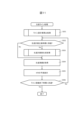
図11は、生産ライン処理のフローの例を示す図である。生産ライン処理は、生産ライン構成の設計のみならず、生産計画の立案に関する処理も含む。生産ライン処理は、インターフェース装置を介してユーザにより開始指示を受け付けると開始される。
まず、主制御部119は、ライン設計案算出処理を行う(ステップS001)。詳細については後述するが、ライン設計案算出処理は、製品設計情報121を用いて生産性設計、ライン構成の設計、生産計画の立案を行い、最適化を行う処理である。
そして、主制御部119は、生産計画の立案時期に到達したか否か判定する(ステップS002)。具体的には、主制御部119は、日時情報を取得し、所定の生産計画立案時期(例えば、週末、月末等)に到達したか否かを判定する。生産計画の立案時期に到達しない場合(ステップS002にて「No」の場合)には、主制御部119は、制御をステップS004へ進める。
生産計画の立案時期に到達している場合(ステップS002にて「Yes」の場合)には、主制御部119は、生産計画案生成処理を行う(ステップS003)。詳細については後述するが、生産計画案生成処理は、ライン構成情報128を用いて、環境負荷と、コストと、スループットのパレート最適解となる生産計画の立案を行う処理である。
そして、環境負荷評価部117は、生産実績を取得する(ステップS004)。具体的には、環境負荷評価部117は、ライン構成情報128に基づいて設置される生産ラインに設けられるリソース候補について稼働実績(例えば、消費電力)を収集し、環境負荷量の実績を算出し、製品ごとに環境負荷量と該環境負荷量の該実績とを算出する。算出した生産実績は、生産実績情報130に格納される。
そして、KPI表示部118は、KPIの予実を表示する(ステップS005)。具体的には、KPI表示部118は、生産ライン設計に関する各種処理により算出された計画値、実績値、設計案、環境負荷等のKPIの予実について、表示する画面を生成する。例えば、KPI表示部118は、後述するライン設計結果画面、パレート解表示画面、生産KPI表示画面等の画面を生成し、出力部150に表示させる。
そして、主制御部119は、ライン稼働終了時期に到達したか否かを判定する(ステップS006)。具体的には、主制御部119は、日時情報を取得し、所定のライン稼働終了時期に到達したか否かを判定する。ライン稼働終了時期に到達しない場合(ステップS006にて「No」の場合)には、主制御部119は、制御をステップS002へ戻す。
ライン稼働終了時期に到達している場合(ステップS006にて「Yes」の場合)には、主制御部119は、生産ライン処理を終了させる。
以上が、生産ライン処理のフローの例である。生産ライン処理によれば、ライン設計を行い、立案時期が到来すると生産計画を立案し、KPIの予実を表示することができる。
図12は、ライン設計案算出処理のフローチャートの例を示す図である。ライン設計案算出処理は生産ライン処理のステップS001において開始される。
まず、工程順序算出部111は、工程順序を算出する(ステップS101)。具体的には、工程順序算出部111は、製品設計情報121を読み込んで製品の構成部品の幾何拘束関係を所定のアルゴリズムで解析し、工程順序を算出する。
そして、製造工法算出部112および内作外注選定部113は、生産性設計案生成処理を行う(ステップS102)。詳細については後述するが、生産性設計案生成処理は、製品の工程順序等を用いて、工程ごとに内作・外注を特定する処理である。
そして、ライン構成算出部114は、ライン構成案生成処理を行う(ステップS103)。詳細については後述するが、ライン構成案生成処理は、製品設計情報121および製品の工程順序等を用いて、環境負荷と、コストと、スループットのパレート最適解となるように内作する工程ごとに生産リソース(ライン構成情報128)を特定する処理である。
そして、生産計画算出部115は、生産計画案生成処理を行う(ステップS104)。生産ライン処理のステップS003と同様、詳細については後述するが、生産計画案生成処理は、ライン構成情報128を用いて環境負荷と、コストと、スループットのパレート最適解となる生産計画の立案を行う処理である。
そして、反復改善部116は、生産性計画案、ライン構成案、生産計画案を評価する(ステップS105)。具体的には、反復改善部116は、ステップS102~S104において出力された生産性設計案、ライン構成案、生産計画案について、コスト、スループット、環境負荷量を算出する。
そして、反復改善部116は、最適案を更新する(ステップS106)。具体的には、反復改善部116は、ステップS102~S104において出力された生産性計画案、ライン構成案、生産計画案を仮の最適案として更新する。
そして、反復改善部116は、更新した最適案のKPIの改善率が未収束か否か判定する(ステップS107)。具体的には、反復改善部116は、更新した最適案のKPIの改善率が所定の閾値(例えば、0.1%)以上の場合には、未収束であると判定する。更新した最適案のKPIの改善率が未収束である場合(ステップS107にて「Yes」の場合)には、反復改善部116は、制御をステップS103に戻し、一部の工程について使用するリソースを一部変更させて再実施させる。
更新した最適案のKPIの改善率が収束した場合(ステップS107にて「No」の場合)には、反復改善部116は、最適案のライン構成案と生産計画についてコスト、スループット、環境負荷を出力部150に出力させる(ステップS108)。
以上が、ライン設計案算出処理のフローの例である。ライン設計案算出処理によれば、生産性設計、ライン構成の設計、生産計画の立案を行い、最適化を行うことができる。
図13は、生産性設計案生成処理のフローチャートの例を示す図である。生産性設計案生成処理は、ライン設計案算出処理のステップS102において開始される。
まず、製造工法算出部112は、製品の工程順序を取得する(ステップS201)。具体的には、製造工法算出部112は、ライン設計案算出処理のステップS101にて算出された製品の工程順序を取得する。
そして、製造工法算出部112は、各工程の製造工程候補情報から工程実施の際の温室効果ガス排出量と製造コスト、スループットを評価する(ステップS202)。具体的には、製造工法算出部112は、工程ごとに製造工程候補情報を入力部140を介して受け付け、受け付けた工程に応じた温室効果ガスの排出量と、製造コストと、スループットとを概算する。なお、その際、製造工法算出部112は、工程ごとに対象の部品とその工法により必要な概算作業時間も入力を受け付けることで、概算作業時間に応じて温室効果ガスの排出量と、製造コストと、スループットと、を算出する。
そして、内作外注選定部113は、製造工程候補情報と外注候補仕様情報123とを用いて、工程ごとに外注先の温室効果ガス排出量と製造コスト、スループットを評価する(ステップS203)。具体的には、内作外注選定部113は、工程種類に応じて担当可能な外注先ごとに、外注した場合の温室効果ガスの排出量と、製造コストと、スループットとを概算する。
そして、内作外注選定部113は、温室効果ガス排出量と、製造コストと、スループットとが最良になるよう多目的数理最適化手法により内作外注を決定する(ステップS204)。具体的には、内作外注選定部113は、温室効果ガス排出量と、製造コストとが最小化し、スループットが最大になるよう多目的数理最適化手法により内作外注を決定する。その際、内作外注選定部113は、温室効果ガス排出量の導出関数と、製造コストの導出関数と、符号を反転したスループットの導出関数とのそれぞれに所定の重みづけを行った合成関数を目的関数として、極小値をとるように内作外注を決定する。
以上が、生産性設計案生成処理のフローの例である。生産性設計案生成処理によれば、温室効果ガス排出量と、製造コストと、スループットとが最良になるよう工程の内作外注を決定することができる。
図14は、ライン構成案生成処理のフローチャートの例を示す図である。ライン構成案生成処理は、ライン設計案算出処理のステップS103において開始される。
まず、ライン構成算出部114は、生産リソース候補仕様情報124と工程順序とを用いて、製品sの工程pごとに、工程を実現可能な生産リソースの集合Rspを抽出する(ステップS301)。
そして、ライン構成算出部114は、生産ライン処理の探索過程で生成した生産リソースの組み合わせであるタブーリストを取得する(ステップS302)。
そして、ライン構成算出部114は、タブーリストの生産リソースの組み合わせを除外して生産リソースの集合Rspから最良の生産リソースを選定する(ステップS303)。最良の生産リソースを選定する際、ライン構成算出部114は、評価指標として、ライン構成のリソースコストと、工程の単位時間当たりの電力消費量と、サプライチェーン温室効果ガス排出量と、が最小となる多目的数理最適化手法を用いる。また、ライン構成算出部114は、内作する工程のいずれかについて、ランダムに外注に変更して最良の生産リソースを選定するようにしてもよい。その際、ヒューリスティックなルールを適用して、ライン構成算出部114は、遠いロケーションの外注先を選ばないようにしてもよい。
そして、ライン構成算出部114は、最良とならなかった生産リソースの組み合わせをタブーリストに追加する(ステップS304)。
以上が、ライン構成案生成処理のフローの例である。ライン構成案生成処理によれば、リソースコストと、工程の電力消費量と、温室効果ガス排出量とが最良になるよう内作工程の生産リソースを決定することができる。
図15は、生産計画案生成処理のフローチャートの例を示す図である。生産計画案生成処理は、ライン設計案算出処理のステップS104と、生産ライン処理のステップS003と、において開始される。すなわち、生産計画案生成処理は、生産ラインの設計時においてのみならず、生産ラインの稼働開始後の運用フェーズにおいても、実行可能である。生産計画案生成処理を運用フェーズにおいても継続して実行することで、生産台数が高く、かつ化石エネルギー源の電力消費量が少なくなるよう生産計画を継続的に立案し、社会の持続可能性に貢献することができる。
まず、生産計画算出部115は、ライン構成により決定した工程について、作業時間Trspを取得する(生産リソースr、製品s、工程p)(ステップS401)。
そして、生産計画算出部115は、作業時間Trspを用いて、作業時刻帯の電力供給源e(電力種類)に応じた電力消費量Werspを見積もる(ステップS402)。
そして、生産計画算出部115は、製品の生産台数を最大化し、かつ、再生可能エネルギー(例えば、「太陽光」、「風力」、「水力」、「波力・潮力」、「流水・潮汐」、「地熱」、「太陽熱」、「大気中の熱その他の自然界に存する熱」、「バイオマス」等)の由来の電力消費量を最大化し、かつ、化石エネルギー由来の電力消費量を最小化する多目的数理最適化手法を用いて、生産リソースrが工程pを実施する作業日時を選定する(ステップS403)。生産計画算出部115は、選定された作業日時を生産計画情報129に反映する。
以上が、生産計画案生成処理のフローの例である。生産計画案生成処理によれば、生産台数が高く、かつ化石エネルギー源の電力消費量が少なくなるよう生産計画を決定することができる。つまり、生産計画案生成処理によれば、太陽光発電等の環境負荷の低い電力を用いる時間帯を優先させて生産計画を立案できる。
図16は、ライン設計結果画面の例を示す図である。ライン設計結果画面500は、ライン設計案算出処理のステップS108において表示される画面の例である。ライン設計結果画面500には、運用期間表示領域510と、工程情報表示領域520と、内作/外作(外注)判定および外注先情報表示領域530と、ライン構成情報表示領域540と、生産計画情報表示領域550と、が含まれる。
工程情報表示領域520には、工程情報126の情報が表示される。すなわち、工程ごとに、工程種別が表示される。
内作/外作(外注)判定および外注先情報表示領域530には、内作・外注情報127の情報が表示される。すなわち、工程ごとに内作・外注の別と、外注の場合には外注先と、が表示される。
ライン構成情報表示領域540には、ライン構成情報128の情報が表示される。すなわち、工程ごとに使用するリソースが表示される。
生産計画情報表示領域550には、生産計画情報129の情報が表示される。すなわち、工程ごとに使用するリソースと、工程の開始時刻と、終了時刻と、電力の種類と、温室効果ガスの排出量と、が表示される。
図17は、パレート解表示画面の例を示す図である。パレート解表示画面600は、ライン設計案算出処理のステップS108において表示される画面の例である。パレート解表示画面600には、表示対象KPI指定受付領域610と、KPIパレート解表示領域620と、が含まれる。
表示対象KPI指定受付領域610は、KPIパレート解表示領域620に表示させるグラフの軸の指定を受け付ける。
KPIパレート解表示領域620は、表示対象KPI指定受付領域610において受け付けた軸でグラフが描画される。このグラフは、ライン設計案ごとにプロットされ、パレート最適解と、候補解と、が区別可能に表示される。
図18は、生産KPI表示画面の例を示す図である。生産KPI表示画面700は、生産ライン処理のステップS005において表示される画面の例である。生産KPI表示画面700には、運用期間表示領域710と、集計日表示領域720と、表示対象温室効果ガス指定受付領域730と、ライン全体の生産KPIの計画と実績表示領域740と、製品指定受付領域750と、製品別生産KPIの計画と実績表示領域760と、が含まれる。
表示対象温室効果ガス指定受付領域730は、生産KPIとして表示する温室効果ガスの種類の指定を受け付ける。
ライン全体の生産KPIの計画と実績表示領域740は、対象のライン全体での生産KPIの計画値と実績値とが対比して表示される。生産KPIには、例えば、平均稼働率、スループット、運用時の温暖化ガス排出量、生産リソースのサプライチェーン排出量(リソース導入時の温室効果ガスの排出量)、外注先での温室効果ガスの排出量、部品調達に関わる温室効果ガスの排出量等が含まれる。
製品指定受付領域750は、生産KPIとして表示する製品の指定を受け付ける。
製品別生産KPIの計画と実績表示領域760は、製品指定受付領域750において受け付けた製品単位の生産KPIの計画値と実績値とが対比して表示される。
以上が、本発明に係る実施例1を適用したライン設計装置である。本発明に係る実施例1の形態によれば、温室効果ガスの排出量を考慮してライン設計を行うことができる。また、生産計画も考慮に入れて最適な工程・ライン設計案を短時間で導出することができ、生産ラインの設計時に運用サイクル全体を視野に入れて温室効果ガス排出量の削減を実現させることができる。
なお、本発明は上記した実施例に限定されるものではなく、様々な変形例が含まれる。例えば、上記した実施例は本発明を分かりやすく説明するために詳細に説明したものであり、必ずしも説明した全ての構成を備えるものに限定されるものではない。また、ある実施例の構成の一部を他の実施例の構成に置き換えることが可能であり、また、ある実施例の構成に他の実施例の構成を加えることも可能である。また、各実施例の構成の一部について、他の構成の追加・削除・置換をすることが可能である。
また、上記の各構成、機能、処理部、処理手段等は、それらの一部又は全部を、例えば集積回路で設計する等によりハードウェアで実現してもよい。また、上記の各構成、機能等は、プロセッサがそれぞれの機能を実現するプログラムを解釈し、実行することによりソフトウェアで実現してもよい。各機能を実現するプログラム、テーブル、ファイル等の情報は、メモリや、ハードディスク、SSD等の記録装置、または、ICカード、SDカード、DVD等の記録媒体に置くことができる。
また、制御線や情報線は説明上必要と考えられるものを示しており、製品上必ずしも全ての制御線や情報線を示しているとは限らない。実際には殆ど全ての構成が相互に接続されていると考えてもよい。
100:ライン設計装置、110:処理部、111:工程順序算出部、112:製造工法算出部、113:内作外注選定部、114:ライン構成算出部、115:生産計画算出部、116:反復改善部、117:環境負荷評価部、118:KPI表示部、119:主制御部、120:記憶部、121:製品設計情報、122:生産物量情報、123:外注候補仕様情報、124:生産リソース候補仕様情報、125:電力供給形態仕様情報、126:工程情報、127:内作・外注情報、128:ライン構成情報、129:生産計画情報、130:生産実績情報、140:入力部、150:出力部、160:通信部。
Claims (14)
- 製品を生産すべき時期および量の情報を含む生産物量情報と、
前記製品の生産に用いるリソース候補の仕様情報を含む生産リソース候補仕様情報と、を記憶する記憶部と、
前記生産物量情報を満たすように、前記リソース候補を用いて前記製品の生産計画情報を算出する生産計画算出部と、
前記生産計画情報を用いて前記製品の生産に係る環境負荷量を評価する環境負荷評価部と、
前記環境負荷量に応じて、前記リソース候補を用いるライン構成情報を出力する出力部と、
を備えることを特徴とするライン設計装置。 - 請求項1に記載のライン設計装置であって、
前記記憶部には、製造工程の一部を担う外部組織の候補およびその環境評価を含む外注候補仕様情報と、前記製品の部品構成を含む製品設計情報と、を記憶し、
前記製品の製造工程の候補を含む製造工程候補情報を受け付ける入力部を備え、
前記環境負荷評価部は、前記外注候補仕様情報と、前記製品設計情報と、前記製造工程候補情報と、を用いて前記環境負荷量を算出し、
該環境負荷量に応じて各製造工程の工法の選定と該製造工程の前記外部組織への依頼の判定を行う内作外注選定部を備え、
前記出力部は、選定された前記工法と前記外部組織への依頼の判定結果を出力する、
ことを特徴とするライン設計装置。 - 請求項1に記載のライン設計装置であって、
前記記憶部には、時刻帯毎の電力消費に伴う前記環境負荷量を特定する電力供給形態仕様情報が含まれ、
前記環境負荷評価部は、前記生産計画情報に含まれる前記リソース候補の稼働時刻帯に応じて前記環境負荷量を算出し、
前記生産計画算出部は、前記環境負荷量がより少なくなるよう前記生産計画情報を算出する、
ことを特徴とするライン設計装置。 - 請求項1に記載のライン設計装置であって、
前記記憶部は、製造工程の一部を担う外部組織の候補およびその環境評価を含む外注候補仕様情報を記憶し、
前記製品の製造工程の候補を含む製造工程候補情報を受け付ける入力部を備え、
前記環境負荷評価部は、前記製造工程の候補ごとに温室効果ガスの排出量を算出し、前記外注候補仕様情報を用いて該製造工程を外部組織へ依頼する場合の前記温室効果ガスの排出量を算出し、前記製造工程の前記環境負荷量として算出し、
該環境負荷量に応じて各製造工程の工法の選定と該製造工程の前記外部組織への依頼の判定を行う内作外注選定部を備え、
前記出力部は、選定された前記工法と前記外部組織への依頼の判定結果を出力する、
ことを特徴とするライン設計装置。 - 請求項1に記載のライン設計装置であって、
前記生産リソース候補仕様情報には、前記リソース候補の仕様情報として、該リソース候補の導入費用と、該リソースの導入時に発生する温室効果ガス排出量と、該リソースの稼働時に発生する温室効果ガス排出量と、が含まれ、
前記環境負荷評価部は、前記製品の製造工程の候補ごとに前記リソース候補の仕様情報を用いて算出する温室効果ガス排出量を前記製造工程の前記環境負荷量として算出し、
該環境負荷量に応じて各製造工程の前記リソース候補の選定を行うライン構成算出部を備え、
前記出力部は、選定された前記リソース候補を出力する、
ことを特徴とするライン設計装置。 - 請求項1に記載のライン設計装置であって、
前記記憶部には、時刻帯毎のエネルギー源の種類を特定する電力供給形態仕様情報が含まれ、
前記環境負荷評価部は、前記生産計画情報に含まれる前記リソース候補の稼働時刻帯に応じて前記エネルギー源を特定して温室効果ガス排出量を算出し、
前記生産計画算出部は、前記温室効果ガス排出量がより少なくなるよう前記生産計画情報を算出する、
ことを特徴とするライン設計装置。 - 請求項6に記載のライン設計装置であって、
前記エネルギー源の種類には、少なくとも太陽光を含む再生可能エネルギー源と、少なくとも火力を含む化石エネルギー源と、が少なくとも含まれ、
前記生産計画算出部は、前記再生可能エネルギー源の利用を優先して前記生産計画情報を算出する、
ことを特徴とするライン設計装置。 - 請求項7に記載のライン設計装置であって、
前記生産計画算出部は、前記再生可能エネルギー源として太陽光を用いる電力の利用を優先して前記生産計画情報を算出する、
ことを特徴とするライン設計装置。 - 請求項1に記載のライン設計装置であって、
少なくとも前記環境負荷量の改善率が収束するまで、前記生産計画情報と、ライン構成情報とを随時変更する反復改善部、
を備えることを特徴とするライン設計装置。 - 請求項1に記載のライン設計装置であって、
前記環境負荷評価部は、前記ライン構成情報に基づいて設置される生産ラインに設けられる前記リソース候補について稼働実績を収集し、前記環境負荷量の実績を算出する、
ことを特徴とするライン設計装置。 - 請求項1に記載のライン設計装置であって、
前記環境負荷評価部は、前記ライン構成情報に基づいて設置される生産ラインに設けられる前記リソース候補について稼働実績を収集し、前記環境負荷量の実績を算出し、前記製品ごとに前記環境負荷量と該環境負荷量の該実績とを算出し、
前記出力部は、前記環境負荷量と該環境負荷量の該実績とを表示する、
ことを特徴とするライン設計装置。 - 請求項1に記載のライン設計装置であって、
前記環境負荷評価部は、前記生産計画情報を用いて前記製品の生産に係る二酸化炭素の排出量を算出し、前記製品の製造工程の前記環境負荷量として算出する、
ことを特徴とするライン設計装置。 - 情報処理装置に生産ラインの設計を行わせるライン設計プログラムであって、
前記情報処理装置は、記憶装置と、プロセッサと、を備え、
前記記憶装置に、製品を生産すべき時期および量の情報を含む生産物量情報と、前記製品の生産に用いるリソース候補の仕様情報を含む生産リソース候補仕様情報と、を記憶させ、
前記プロセッサを、
前記生産物量情報を満たすように、前記リソース候補を用いて前記製品の生産計画情報を算出する生産計画算出部と、
前記生産計画情報を用いて前記製品の生産に係る環境負荷量を評価する環境負荷評価部と、
前記環境負荷量に応じて、前記リソース候補を用いるライン構成情報を出力する出力部、
として動作させることを特徴とするライン設計プログラム。 - 情報処理装置を用いて生産ラインの設計を行うライン設計方法であって、
前記情報処理装置は、
製品を生産すべき時期および量の情報を含む生産物量情報と、前記製品の生産に用いるリソース候補の仕様情報を含む生産リソース候補仕様情報と、を記憶する記憶部と、処理部と、を備え、
前記処理部は、
前記生産物量情報を満たすように、前記リソース候補を用いて前記製品の生産計画情報を算出する生産計画算出手順と、
前記生産計画情報を用いて前記製品の生産に係る環境負荷量を評価する環境負荷評価手順と、
前記環境負荷量に応じて、前記リソース候補を用いるライン構成情報を出力する出力手順、
を実施することを特徴とするライン設計方法。
Applications Claiming Priority (2)
| Application Number | Priority Date | Filing Date | Title |
|---|---|---|---|
| JP2023-015774 | 2023-02-06 | ||
| JP2023015774A JP2024111348A (ja) | 2023-02-06 | 2023-02-06 | ライン設計装置、ライン設計プログラムおよびライン設計方法 |
Publications (1)
| Publication Number | Publication Date |
|---|---|
| WO2024166455A1 true WO2024166455A1 (ja) | 2024-08-15 |
Family
ID=92262816
Family Applications (1)
| Application Number | Title | Priority Date | Filing Date |
|---|---|---|---|
| PCT/JP2023/039013 Ceased WO2024166455A1 (ja) | 2023-02-06 | 2023-10-30 | ライン設計装置、ライン設計プログラムおよびライン設計方法 |
Country Status (2)
| Country | Link |
|---|---|
| JP (1) | JP2024111348A (ja) |
| WO (1) | WO2024166455A1 (ja) |
Citations (5)
| Publication number | Priority date | Publication date | Assignee | Title |
|---|---|---|---|---|
| JP2011175463A (ja) * | 2010-02-24 | 2011-09-08 | Hitachi Ltd | 生産計画決定支援方法および装置 |
| JP2016136328A (ja) * | 2015-01-23 | 2016-07-28 | 株式会社日立製作所 | 環境負荷評価装置、及び環境負荷評価方法 |
| US20190354641A1 (en) * | 2018-05-21 | 2019-11-21 | Arizona Board Of Regents On Behalf Of The University Of Arizona | Systems and methods for simulation-based resource and layout optimization |
| JP2022131505A (ja) * | 2021-02-26 | 2022-09-07 | 株式会社日立製作所 | 生産ライン設計装置、生産ライン設計システムおよび生産ライン設計方法 |
| JP2023015847A (ja) * | 2021-07-20 | 2023-02-01 | トヨタ自動車株式会社 | 情報処理装置、情報処理方法、及びプログラム |
-
2023
- 2023-02-06 JP JP2023015774A patent/JP2024111348A/ja active Pending
- 2023-10-30 WO PCT/JP2023/039013 patent/WO2024166455A1/ja not_active Ceased
Patent Citations (5)
| Publication number | Priority date | Publication date | Assignee | Title |
|---|---|---|---|---|
| JP2011175463A (ja) * | 2010-02-24 | 2011-09-08 | Hitachi Ltd | 生産計画決定支援方法および装置 |
| JP2016136328A (ja) * | 2015-01-23 | 2016-07-28 | 株式会社日立製作所 | 環境負荷評価装置、及び環境負荷評価方法 |
| US20190354641A1 (en) * | 2018-05-21 | 2019-11-21 | Arizona Board Of Regents On Behalf Of The University Of Arizona | Systems and methods for simulation-based resource and layout optimization |
| JP2022131505A (ja) * | 2021-02-26 | 2022-09-07 | 株式会社日立製作所 | 生産ライン設計装置、生産ライン設計システムおよび生産ライン設計方法 |
| JP2023015847A (ja) * | 2021-07-20 | 2023-02-01 | トヨタ自動車株式会社 | 情報処理装置、情報処理方法、及びプログラム |
Also Published As
| Publication number | Publication date |
|---|---|
| JP2024111348A (ja) | 2024-08-19 |
Similar Documents
| Publication | Publication Date | Title |
|---|---|---|
| Abbasi et al. | BIM-based combination of takt time and discrete event simulation for implementing just in time in construction scheduling under constraints | |
| KR102184182B1 (ko) | Super Tree 기반의 Project/Task 지능 목표관리 방법 및 플랫폼 | |
| Talbot | Resource-constrained project scheduling with time-resource tradeoffs: The nonpreemptive case | |
| Dietmair et al. | A generic energy consumption model for decision making and energy efficiency optimisation in manufacturing | |
| Zeng et al. | BIM-enabled Kanban system in construction logistics for real-time demand reporting and pull replenishment | |
| Hemmati Far et al. | A fuzzy bi-objective flexible cell scheduling optimization model under green and energy-efficient strategy using Pareto-based algorithms: SATPSPGA, SANRGA, and NSGA-II | |
| Stoughton et al. | Direct construction of optimal generation mix | |
| Kmiecik | Creating a genetic algorithm for third-party logistics’ warehouse delivery scheduling via a large language model | |
| Sonmez et al. | Activity uncrashing heuristic with noncritical activity rescheduling method for the discrete time-cost trade-off problem | |
| WO2023005395A1 (zh) | 工业规划的方法、装置、设备、存储介质和程序产品 | |
| Liu et al. | Aggregate production planning for shipbuilding with variation-inventory trade-offs | |
| Zohrehvandi et al. | A fuzzy project buffer management algorithm: a case study in the construction of a renewable project | |
| Zheng et al. | Block spatial scheduling modelling and application in shipbuilding | |
| Ren et al. | A multi-criteria decision support model for adopting energy efficiency technologies in the iron and steel industry | |
| Wang et al. | Resilience factors and mechanisms in the coal power supply chain: A quantitative analysis using fuzzy DEMATEL, ISM, and ANP methods | |
| Guo et al. | Dynamic pricing models in e-commerce: Exploring machine learning techniques to balance profitability and customer satisfaction | |
| Afrin et al. | Towards green automated production line with rotary transfer and turrets: a multi-objective approach using a binary scatter tabu search procedure | |
| WO2024166455A1 (ja) | ライン設計装置、ライン設計プログラムおよびライン設計方法 | |
| CN115630794A (zh) | 一种煤层气井维修智能巡检调度方法 | |
| Zhang et al. | Hybrid particle swarm optimization algorithms for cost-oriented robotic assembly line balancing problems | |
| Zaporozhets et al. | Software and Information Complex for Modeling Integrated Multi-node and Autonomous Electric and Heat Supply Systems | |
| Zhang et al. | An integrated optimization method for multi-load AGVs and FJSP production scheduling based on DDQN-MCTS hybrid algorithm | |
| CN119578701A (zh) | 电工装备碳足迹确定方法、装置、电子设备及存储介质 | |
| Alismail | Chance constraints optimal planning strategy of energy storage systems and Tie-Lines under wind power uncertainties to improve the reliability | |
| AU2010314809B2 (en) | System and method for business decision-making |
Legal Events
| Date | Code | Title | Description |
|---|---|---|---|
| 121 | Ep: the epo has been informed by wipo that ep was designated in this application |
Ref document number: 23921278 Country of ref document: EP Kind code of ref document: A1 |
|
| NENP | Non-entry into the national phase |
Ref country code: DE |
|
| 122 | Ep: pct application non-entry in european phase |
Ref document number: 23921278 Country of ref document: EP Kind code of ref document: A1 |