WO2024166398A1 - 制御装置、制御方法および制御プログラム - Google Patents
制御装置、制御方法および制御プログラム Download PDFInfo
- Publication number
- WO2024166398A1 WO2024166398A1 PCT/JP2023/004661 JP2023004661W WO2024166398A1 WO 2024166398 A1 WO2024166398 A1 WO 2024166398A1 JP 2023004661 W JP2023004661 W JP 2023004661W WO 2024166398 A1 WO2024166398 A1 WO 2024166398A1
- Authority
- WO
- WIPO (PCT)
- Prior art keywords
- flow
- priority
- route
- priority packets
- new
- Prior art date
- Legal status (The legal status is an assumption and is not a legal conclusion. Google has not performed a legal analysis and makes no representation as to the accuracy of the status listed.)
- Ceased
Links
Images





Classifications
-
- H—ELECTRICITY
- H04—ELECTRIC COMMUNICATION TECHNIQUE
- H04L—TRANSMISSION OF DIGITAL INFORMATION, e.g. TELEGRAPHIC COMMUNICATION
- H04L45/00—Routing or path finding of packets in data switching networks
- H04L45/30—Routing of multiclass traffic
-
- H—ELECTRICITY
- H04—ELECTRIC COMMUNICATION TECHNIQUE
- H04L—TRANSMISSION OF DIGITAL INFORMATION, e.g. TELEGRAPHIC COMMUNICATION
- H04L45/00—Routing or path finding of packets in data switching networks
- H04L45/42—Centralised routing
-
- H—ELECTRICITY
- H04—ELECTRIC COMMUNICATION TECHNIQUE
- H04L—TRANSMISSION OF DIGITAL INFORMATION, e.g. TELEGRAPHIC COMMUNICATION
- H04L47/00—Traffic control in data switching networks
- H04L47/10—Flow control; Congestion control
- H04L47/24—Traffic characterised by specific attributes, e.g. priority or QoS
Definitions
- the present invention relates to a control device, a control method, and a control program.
- Priority packets that require real-time performance such as for controlling a robot in a remote location, are transferred with priority over other non-priority packets that do not require real-time performance in order to guarantee communication delays and delay fluctuations (jitter).
- QoS Quality of Service
- TAS Time Aware Shaper
- non-priority flows may not be able to increase the number of flows that can be accommodated in a network, including flows of non-priority packets (non-priority flows).
- non-priority flows For example, when using TAS, the timing at which each transfer device blocks a non-priority gate can be synchronized, but no control is implemented over the communication path or transmission timing of the priority traffic that flows. Therefore, there is a possibility that a concentration of priority packets will arrive at a specific time, causing the priority packet queue to overflow, or that priority packets will arrive at various times, causing non-priority gates to continue to be blocked, significantly impacting the non-priority packets.
- Network slice users can reduce slice usage fees by minimizing the network resources they use, but they will need control to ensure that fewer resources can accommodate the number of priority flows.
- a priority flow although it is best effort, needs to occupy resources to secure bandwidth to meet strict delay fluctuation requirements, and it may not be possible to change the route. For this reason, for example, it may be possible to increase the amount of resources available to a non-priority flow by reducing the resources occupied by the priority flow, but with conventional technology, it was sometimes impossible to increase the amount of resources available to a non-priority flow unless the resources occupied by the priority flow could be reduced.
- the present invention was made in consideration of the above-mentioned problems, and aims to increase the number of flows, including non-priority flows, that can be accommodated in a network.
- the control device is characterized by having an acquisition unit that acquires topology information indicating the connection form of the network and information on the forwarding delay of each forwarding device that forwards priority packets and non-priority packets, a determination unit that, when a new priority packet flow is added, determines at least one of the path and transmission timing of the new priority packet flow and the path of the non-priority packet flow based on the topology information and the forwarding delay information of each forwarding device acquired by the acquisition unit, and, when a new non-priority packet flow is added, determines the path of the new non-priority packet flow and the path of the non-priority packet flow based on the topology information and the forwarding delay information of each forwarding device acquired by the acquisition unit, and a setting unit that sets the path and transmission timing of the new priority packet flow and the path of the non-priority packet flow determined by the determination unit, or the path of the new non-priority packet flow and the path of the non-
- the present invention makes it possible to increase the number of flows that can be accommodated in a network, including non-priority flows.
- FIG. 1 is a diagram illustrating an example of the configuration of a control system according to the first embodiment.
- FIG. 2 is a diagram illustrating an example of the configuration of the control device according to the first embodiment.
- FIG. 3 illustrates an example of a flow addition procedure according to the first embodiment.
- FIG. 4 illustrates an example of a flow addition procedure according to the first embodiment.
- FIG. 5 is a diagram illustrating an example of adding a flow according to the first embodiment.
- FIG. 6 is a diagram illustrating an example of adding a flow according to the first embodiment.
- FIG. 7 is a flowchart illustrating an example of a flow addition according to the first embodiment.
- FIG. 8 is a flowchart illustrating an example of a flow addition according to the first embodiment.
- FIG. 1 is a diagram illustrating an example of the configuration of a control system according to the first embodiment.
- FIG. 2 is a diagram illustrating an example of the configuration of the control device according to the first embodiment.
- FIG. 3 illustrates an
- FIG. 9 is a diagram illustrating an example of the configuration of a control system according to the second embodiment.
- FIG. 10 is a diagram illustrating an example of the configuration of the control device according to the second embodiment.
- FIG. 11 illustrates an example of a flow deletion procedure according to the second embodiment.
- FIG. 12 illustrates an example of a flow deletion procedure according to the second embodiment.
- FIG. 13 is a diagram illustrating an example of flow deletion according to the second embodiment.
- FIG. 14 is a diagram illustrating an example of flow deletion according to the second embodiment.
- FIG. 15 is a flowchart illustrating an example of flow deletion according to the second embodiment.
- FIG. 16 is a flowchart illustrating an example of flow deletion according to the second embodiment.
- FIG. 17 is a diagram illustrating a computer that executes a control program according to the embodiment.
- First Embodiment A first embodiment will be described below.
- a case will be described in which, when a new priority flow is added, a new priority flow and a non-priority flow are optimized, and, when a new non-priority flow is added, all non-priority flows are optimized.
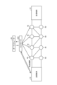
- Fig. 1 is a diagram illustrating an example of the configuration of the control system 1 according to the first embodiment.
- the system illustrated in Fig. 1 includes a transmitting terminal 10, a controller (control device) 200, an orchestrator 30, and a transfer device 40.
- the control system 1 may be realized by a plurality of devices.
- each component of the control system 1 may be allocated to the plurality of devices in any manner.
- the transmitting terminal 10 makes a request to the controller 200 to add a new flow of priority packets (new priority flow) or a new flow of non-priority packets (new non-priority flow).
- the transmitting terminal 10 also transmits a request to add a new flow in accordance with the transmission timing setting received from the controller 200.
- the controller 200 performs calculations in response to the request to add a new flow from the transmitting terminal 10. If the result of the calculation shows that there are insufficient network resources (resources), the controller 200 requests the orchestrator 30 to add resources.
- the controller 200 also sets flow control for the transmitting terminal 10 or the transfer device 40. Details of the controller 200 will be described later.
- the orchestrator 30 is an external device that manages slices.
- the orchestrator 30 adds resources in response to a resource addition request from the controller 200.
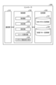
- Fig. 2 is a diagram showing an example of the configuration of the controller 200 according to the first embodiment.
- the controller 200 includes a communication unit 210, a control unit 220, and a storage unit 230. Each of these units may be held in a distributed manner in a plurality of devices. The processing of each of these units will be described below.
- the communication unit 210 is realized by a NIC (Network Interface Card) or the like, and enables communication between the control unit 220 and external devices via telecommunication lines such as a LAN (Local Area Network) or the Internet.
- the communication unit 210 enables communication between the control unit 220 and the transfer device 40 or external devices.
- the storage unit 230 is realized by a semiconductor memory element such as a random access memory (RAM) or a flash memory, or a storage device such as a hard disk or an optical disk.
- the storage unit 230 has a network topology storage unit 231 and an accommodation flow storage unit 232.
- the NW topology storage unit 231 stores topology information, which is configuration information of the network, as well as information on the delay time, maximum flow rate, and minimum open time of non-priority gates of each transfer device 40.
- the accommodated flow storage unit 232 stores information on the target delay time, source node, and destination node of flows that have already been accommodated. Note that the above content is an example, and the items stored in the NW topology storage unit 231 and the accommodated flow storage unit 232 are not limited to those listed here.
- the control unit 220 is realized using a CPU (Central Processing Unit), NP (Network Processor), FPGA (Field Programmable Gate Array), etc., and executes processing programs stored in memory. As a result, the control unit 220 functions as an acquisition unit 221, a determination unit 222, a setting unit 223, a resource request unit 224, and a topology update reception unit 225. Note that each of these functional units may be implemented in different hardware.
- the control unit 220 may also include other functional units.
- the acquisition unit 221 acquires topology information indicating the connection form of the network and information on the forwarding delay of each forwarding device that forwards priority packets and non-priority packets.
- the acquisition unit 221 may further acquire information on the minimum opening time of the non-priority gate in each forwarding device.
- the acquisition unit 221 acquires topology information indicating the connection form of the network, the forwarding delay of the forwarding device 40, the maximum flow rate, and the minimum opening time of the non-priority gate from the NW topology storage unit 231.
- the acquisition unit 221 also acquires the target delay time of the accommodated flow and information on the source node and destination node from the accommodated flow storage unit 232.
- the acquisition unit 221 acquires information on the source node, destination node, and target delay time of the new flow from the transmitting terminal 10.
- the acquisition unit 221 may also acquire information on the bandwidth of each link between each forwarding device 40.
- the determination unit 222 determines the path and transmission timing of the flow based on the topology information acquired by the acquisition unit 221 and the information on the forwarding delay of each transfer device 40. Specifically, when a new priority flow is added, the determination unit 222 determines at least one of the path and transmission timing of the new priority flow and the path of the non-priority flow based on the topology information acquired by the acquisition unit 221 and the information on the forwarding delay of each transfer device 40. In addition, when a new non-priority flow is added, the determination unit 222 determines the path of the new non-priority flow and the path of the non-priority flow based on the topology information acquired by the acquisition unit 221 and the information on the forwarding delay of each transfer device 40.
- the determination unit 222 determines the path and transmission timing of a new priority flow when a new priority flow is added.
- the determination unit 222 may determine the path and transmission timing of a new priority flow such that the delay time until the new priority flow is transmitted from the source node to the destination node is within a target delay time preset for each new priority flow and the time that the non-priority gate is open is equal to or longer than the minimum opening time set for the non-priority gate.
- the determination unit 222 determines at least one of the path and transmission timing of the new priority flow based on the information stored in the storage unit 230 and the information notified from the transmitting terminal 10.
- the transmission timing refers to the timing at which the transfer device 40 transfers the new priority flow.
- the transmission timing is not limited to the above example, and may be the timing at which the transmitting terminal 10 transmits the new priority flow.
- the determination unit 222 determines the route and transmission timing of the new priority flow based on topology information indicating the network connection form held by the NW topology storage unit 231, information on the transfer delay of the transfer device 40 and the minimum opening time of the non-priority gate, and information on the source node, destination node, and target delay time of the new priority flow notified from the transmitting terminal 10, so that the delay time until the new priority flow is transferred from the source node to the destination node is within the target time of the new priority flow and the same transfer device 40 is not transferred more than its capacity in the same period.
- the decision unit 222 may use the optimal solution that is the result of the calculation by the linear programming problem solver to calculate the route and transmission timing of the new priority flow.
- the decision unit 222 formulates a linear programming problem using the following objective function (i) or the like based on topology information, information on the transfer delay of the transfer device 40 and the minimum opening time of the non-priority gate, and information on the source node, destination node, and target delay time of the new priority flow notified from the transmitting terminal 10, and passes it to the linear programming problem solver and accepts the return of the variable results.
- the objective function (i) of the linear programming problem is set to, for example, minimize the blocking time of non-priority gates at the node, minimize priority packets that do not satisfy QoS, and minimize the blocking time of non-priority gates at the node in all time slots, as shown in the following formula (1).
- K represents the set of all priority packets.
- T represents the set of all time slots.
- V represents the set of all network nodes.
- close v represents a binary variable to which 1 is assigned if the non-priority gate of node v is closed in time slot t.
- ⁇ represents a sufficiently small value for the first term.
- pBlock k represents a binary variable to which 1 is assigned if priority flow k does not satisfy QoS (Quality of Service).
- ⁇ represents a sufficiently small value for the second term.
- close v,t represents a binary variable to which 1 is assigned if the non-priority gate of node v is closed in time slot t.
- the pre-held parameters are the topology, the forwarding delay of each forwarding device 40, the maximum flow rate of each link between each forwarding device 40, and the minimum opening time of the non-priority gate at each node.
- the determination unit 222 determines the route and transmission timing of the new priority flow by obtaining a real solution using the target delay time information, which is a parameter of the existing priority flow that has already been accommodated, the departure node and arrival node as constants, and the route and transmission timing of the additional priority flow as variables.
- the determination unit 222 may determine the route of the non-priority flow based on the bandwidth information acquired by the acquisition unit 221.
- the decision unit 222 may use the optimal solution that is the result of the calculation by the linear programming problem solver to calculate the route of the non-priority flow.
- the decision unit 222 formulates a linear programming problem using the following objective function (ii) or the like based on topology information, information on the forwarding delay of the forwarding device 40, information on the source node, destination node, and target delay time of the new priority flow notified from the transmitting terminal 10, and information on the bandwidth of each link between each forwarding device 40, passes the problem to the linear programming problem solver, and accepts the return of the variable results.
- the objective function (ii) of the linear programming problem is set to, for example, minimize non-priority packets that do not satisfy the QoS and minimize the maximum bandwidth of each link between each transfer device 40, as shown in the following formula (2).
- K represents the set of all priority packets.
- E represents the set of all links.
- bBlock k represents a binary variable that is set to 1 if non-priority flow K does not satisfy the QoS.
- ⁇ represents a sufficiently small value for the first term.
- Bandwidth i,j represents the bandwidth used on the link from node i to node j.
- the pre-held parameters are the topology, the forwarding delay of each forwarding device 40, the maximum flow rate of each link between each forwarding device 40, and the accommodation status of each priority flow.
- the determination unit 222 determines the route of the non-priority flow by obtaining a real solution using the target delay time information, which is the parameter of all non-priority flows, and the departure node and arrival node as variables.
- the above example describes the specific process of determining the routes of non-priority flows by the determination unit 222 when a new priority flow is added, and therefore the non-priority flow does not include the new non-priority flow.
- the determination unit 222 determines the routes of all non-priority flows in the same manner as when a new priority flow is added, except that the determination unit 222 determines the routes of all non-priority flows including the new non-priority flow in addition to the existing non-priority flows that have already been accommodated.
- the determination unit 222 determines the routes of the non-priority flows in the same manner as the above example, except that the determination unit 222 determines the routes of all non-priority flows including the new non-priority flow in addition to the routes of the existing non-priority flows.
- the setting unit 223 sets the path and transmission timing of the flow determined by the determination unit 222 to the transfer device 40 or the transmitting terminal 10. Specifically, the setting unit 223 sets at least one of the path and transmission timing of the new priority flow determined by the determination unit 222 and the path of the non-priority flow, or the path of the new non-priority flow and the path of the non-priority flow to the transfer device 40 or the transmitting terminal 10. Furthermore, when the transmission timing of the new priority flow is determined by the determination unit 222, the setting unit 223 sets the timing of transferring the flow of the transfer device 40 as the transmission timing determined by the determination unit 222. Furthermore, the setting unit 223 sets the timing of transmitting the flow of the transmitting terminal 10 as the transmission timing determined by the determination unit 222.
- the resource request unit 224 requests an increase in the bandwidth of the link between each transfer device 40 whose flow rate exceeds the maximum flow rate of each transfer device 40.
- the resource request unit 224 may request additional resources from an external device.
- an external device to which the resource request unit 224 requests additional resources is the orchestrator 30.
- the resource request unit 224 requests an external device to add resources necessary to determine the flow path and transmission timing such that the delay time until the flow is transmitted from the source node to the destination node is within a target delay time preset for each flow, and the time that a non-priority gate is open is equal to or longer than the minimum open time set for the non-priority gate.
- the topology update reception unit 225 receives updates to topology information indicating the connection form of the network and stores it in the NW topology storage unit 231. For example, when a new priority flow or a new non-priority flow is added and the connection form of the network is changed, the topology update reception unit 225 receives notification of the topology update and stores the new topology information by storing it in the NW topology storage unit 231.
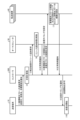
- Fig. 3 and Fig. 4 are diagrams showing an example of a flow addition procedure by the control system 1 according to the first embodiment.
- the control system 1 of this embodiment includes a transmitting terminal 10, a controller 200, an orchestrator 30, and a forwarding device 40.
- the transmitting terminal 10 requests the controller 200 to add a new priority flow (1).
- the transmitting terminal 10 notifies the controller 200 of information on the source node, destination node, and target delay of the new priority flow to be added.
- the controller 200 determines the route and transmission timing of the new priority flow and the route of the non-priority flow based on the source node, destination node, target delay information, topology information, and forwarding delay information of the forwarding device 40 of the new priority flow notified by the transmitting terminal 10 (2). If the controller 200 cannot determine the route and transmission timing of the new priority flow or the route of the non-priority flow, it determines that there are insufficient resources and requests the orchestrator 30 to add a minimum number of resources, such as pre-specified links (3).
- the orchestrator 30 which has received a request from the controller 200 to add the minimum number of resources, performs the resource addition process (4). After that, the orchestrator 30 notifies the controller 200 that the resource addition process has been successfully performed (5).
- the controller 200 then sets the determined path and transmission timing of the new priority flow and the path of the non-priority flow in the transfer device 40 (6). As a result, the path and transmission timing of the new priority flow and the path of the non-priority flow are set in the transfer device 40 (7).
- the transfer device 40 notifies the controller 200 that the path and transmission timing of the new priority flow and the path of the non-priority flow have been set successfully (8).
- the controller 200 sets the transmission timing of the new priority flow in the transmitting terminal 10 and permits it to start transmitting (9). Then, the transmitting terminal 10 starts transmitting the new priority flow (10).
- the controller 200 determines both the path and the transmission timing of the new priority flow, but it is sufficient to determine at least one of the path and the transmission timing of the new priority flow.
- the controller 200 may determine only one of the path and the transmission timing of the new priority flow, i.e., the path or the transmission timing of the new priority flow. In either case, it is possible to increase the number of flows that can be accommodated in the network.
- the control system 1 of this embodiment includes a transmitting terminal 10, a controller 200, an orchestrator 30, and a forwarding device 40.
- the transmitting terminal 10 requests the controller 200 to add a new non-priority flow (11). In this case, the transmitting terminal 10 notifies the controller 200 of information on the source node, destination node, and target delay of the new non-priority flow that is requested to be added.
- the controller 200 determines the route of the new non-priority flow and the route of the non-priority flow (routes of all non-priority flows) based on the source node, destination node, and target delay information of the new non-priority flow notified by the transmitting terminal 10, topology information, and forwarding delay information of the forwarding device 40 (12).
- controller 200 If the controller 200 cannot determine the route of the new non-priority flow and the route of the non-priority flow, it determines that there is a resource shortage, and requests the orchestrator 30 to add a minimum amount of resources, such as pre-specified links (13).
- the orchestrator 30 which has received a request from the controller 200 to add the minimum number of resources, performs the resource addition process (14). After that, the orchestrator 30 notifies the controller 200 that the resource addition process has been successfully performed (15).
- the controller 200 then sets the determined new non-priority flow path and non-priority flow path in the transfer device 40 (16). As a result, the new non-priority flow path and non-priority flow path are set in the transfer device 40 (17). Next, the transfer device 40 notifies the controller 200 that the new non-priority flow path and non-priority flow path have been set successfully (18). Next, the controller 200 permits the transmitting terminal 10 to start transmission (19). Then, the transmitting terminal 10 starts transmitting the new non-priority flow (20).
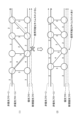
- FIG. 5 and Fig. 6 are diagrams showing an example of flow addition by the control system 1 according to the first embodiment.
- FIG. 5 (1) shows a flow for which no route is set
- FIG. 5 (1) shows non-priority flows (i) and (ii), a priority flow, a new priority flow, and the delay time for each link between each transfer device 40.
- FIG. 5 (2) shows a flow controlled by route setting.
- the controller 200 performs flow control, sets routes for the new priority flow and non-priority flows (i) and (ii), and modifies the routes of the non-priority flows (i) and (ii) by rearranging them. In this way, the controller 200 eliminates overlap between the route for the non-priority flow (ii), the route for the priority flow, and the route for the new priority flow.
- the controller 200 performs optimization calculation (i) to calculate the route and transmission timing of a new priority flow that ensures the minimum opening time of each non-priority gate and minimizes the blocking time of the non-priority gate while avoiding congestion.
- the controller 200 performs optimization calculation (ii) to calculate the route of the non-priority flow that minimizes the number of non-priority packets that do not satisfy the QoS and minimizes the maximum bandwidth of each link between each transfer device 40.
- the controller 200 sets the route of the new priority flow obtained by the optimization calculation (i) for the forwarding device 40, thereby forwarding the new priority flow from the source node to the destination node within the target delay time. In this way, the controller 200 ensures the minimum opening time of the non-priority gates by reducing the load on the forwarding device 40, and maximizes the flow forwarding efficiency.
- the controller 200 avoids congestion that occurs when the total amount of colliding traffic exceeds the maximum flow rate of the forwarding device 40. In addition, this causes the controller 200 to increase the number of flows, including non-priority flows, that can be accommodated in the network.
- FIG. 6 (1) shows a flow for which no route is set
- FIG. 6 (1) shows a non-priority flow, a new non-priority flow, priority flows (i) and (ii), and the delay time for each link between each transfer device 40.
- FIG. 6 (2) shows a flow controlled by route setting.
- the controller 200 performs flow control, sets routes for the non-priority flow and the new non-priority flow, and modifies the routes of the non-priority flows (i) and (ii) by rearranging them. In this way, the controller 200 eliminates overlap between the route of the new non-priority flow, the route of the priority flow (i), and the route of the priority flow (ii).
- the controller 200 performs an optimization calculation (ii) to calculate a route for a non-priority flow that minimizes non-priority packets that do not satisfy the QoS and minimizes the maximum bandwidth of each link between each transfer device 40.
- the controller 200 sets the route for the non-priority flow obtained by the optimization calculation (ii) for the transfer device 40, thereby avoiding congestion that occurs when the total amount of colliding traffic exceeds the maximum flow rate of the transfer device 40. This also causes the controller 200 to increase the number of flows, including non-priority flows, that can be accommodated in the network.
- Flowchart A flow of flow control (flow addition) by path setting of the controller 200 according to the first embodiment when a new flow is added will be described with reference to Fig. 7 and Fig. 8.
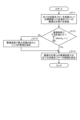
- Fig. 7 and Fig. 8 are flowcharts showing an example of the flow of flow addition according to the first embodiment.
- the decision unit 222 of the controller 200 performs optimization calculation (i) with the existing flow as a constant and the added priority flow as a variable (step S101). Specifically, the decision unit 222 performs optimization calculation (i) with the path and transmission timing of the existing flow as constants and the path and transmission timing of the added priority flow as variables, to minimize the blocking time of non-priority gates while ensuring the minimum opening time of each non-priority gate and avoiding congestion.
- the resource request unit 224 of the controller 200 determines whether the optimal variable satisfies the following formula (3) based on the result of the calculation by the decision unit 222 (step S102).
- the optimal variable does not satisfy the following formula (3) (step S102 "No"), it means that there is a resource shortage.
- the optimal variable satisfies the following formula (3) (step S102 "Yes"), it means that there is no resource shortage.
- the resource request unit 224 determines that the optimal variables do not satisfy the following formula (3) (step S102 "No"), it requests the addition of bandwidth to the transfer device 40 whose flow rate exceeds the maximum flow rate with the optimal variables (step S103).
- the resource request unit 224 requests an increase in the bandwidth of the link between each transfer device 40 whose flow rate exceeds the maximum flow rate of each transfer device 40.
- step S102 If the optimization variables satisfy the above formula (3) (step S102 "Yes"), or after completing the processing of step S103, the decision unit 222 performs optimization calculation (ii) for the non-priority flows with objective function (ii) using all non-priority flows as variables (step S104). Specifically, the decision unit 222 performs optimization calculation (ii) for calculating the route of the non-priority flows that minimizes non-priority packets that do not satisfy QoS and minimizes the maximum bandwidth of each link between each transfer device 40 using all non-priority flows as variables.
- the resource request unit 224 determines whether the optimal variables satisfy the following formula (4) based on the calculation results by the determination unit 222 (step S105). Here, if the optimal variables do not satisfy the following formula (4) (step S105 "No"), this means that there is a resource shortage. On the other hand, if the optimal variables satisfy the following formula (4) (step S105 "Yes”), this means that there is no resource shortage.
- the resource request unit 224 determines that the optimal variables do not satisfy the following formula (4) (step S105 "No"), it requests the addition of bandwidth to the transfer device 40 whose flow rate exceeds the maximum flow rate with the optimal variables (step S106).
- the resource request unit 224 requests an increase in the bandwidth of the link between each transfer device 40 whose flow rate exceeds the maximum flow rate of each transfer device 40.
- step S105 the setting unit 223 sets the route and transmission timing of the new priority flow and the route of the non-priority flow determined by the decision unit 222. Specifically, the setting unit 223 sets the route and transmission timing of the new priority flow with the optimal variables of the optimization calculation (i) and the route of the non-priority flow with the optimal variables of the optimization calculation (ii) for the transfer device 40 or the sending terminal 10, and transfers the flow (step S107).
- the decision unit 222 performs an optimization calculation (ii) of the non-priority flow with the objective function (ii) using the new non-priority flow and existing non-priority flows (all non-priority flows) as variables (step S111). Specifically, the decision unit 222 performs an optimization calculation (ii) that uses all non-priority flows as variables to minimize non-priority packets that do not satisfy the QoS and calculates a route for the non-priority flow that minimizes the maximum bandwidth of each link between each transfer device 40.
- the resource request unit 224 determines whether the optimal variables satisfy the above formula (4) as a result of the calculation by the determination unit 222 (step S112). If the resource request unit 224 determines that the optimal variables do not satisfy the following formula (4) (step S112 "No"), the resource request unit 224 requests the addition of bandwidth to the transfer device 40 whose optimal variables exceed the maximum flow rate (step S113). In other words, when the route of a non-priority flow is determined by the determination unit 222, if the non-priority packets do not satisfy the QoS, the resource request unit 224 requests an increase in the bandwidth of the link between each transfer device 40 whose flow rate exceeds the maximum flow rate of each transfer device 40.
- step S112 If the optimal variables satisfy the above formula (4) (step S112 "Yes"), or if the processing of step S112 is completed, the setting unit 223 sets the route of the new non-priority flow and the route of the non-priority flow determined by the determination unit 222. Specifically, the setting unit 223 sets routes for all non-priority flows for the optimal variables of the optimization calculation (ii) for the transfer device 40 or the sending terminal 10, and transfers the flows (step S114).
- the controller 200 includes an acquisition unit 221, a determination unit 222, and a setting unit 223.
- the acquisition unit 221 acquires topology information indicating the connection form of the network and information on the transfer delay of each transfer device 40 that transfers the priority packet and the non-priority packet.
- the determination unit 222 determines at least one of the path and transmission timing of the new priority packet flow and the path of the non-priority packet flow based on the topology information acquired by the acquisition unit 221 and the information on the transfer delay of each transfer device 40.
- the determination unit 222 determines the path of the new non-priority packet flow and the path of the non-priority packet flow based on the topology information acquired by the acquisition unit 221 and the information on the transfer delay of each transfer device 40.
- the setting unit 223 sets at least one of the flow path and transmission timing of new priority packets and the flow path of non-priority packets, or the flow path of new non-priority packets and the flow path of non-priority packets, determined by the determination unit 222, to the transfer device 40 or the transmitting terminal 10.
- the controller 200 can increase the number of flows, including non-priority flows, that can be accommodated in the network based on the acquired information. Specifically, when a new priority flow is added, the controller 200 uses the collected information to set at least one of the route and transmission timing of the new priority flow, and the route of the non-priority flow, for the transmitting terminal 10 or the transfer device 40. Also, when a new non-priority flow is added, the controller 200 uses the collected information to set routes for all non-priority flows for the transmitting terminal 10 or the transfer device 40.
- the controller 200 optimizes not only the new priority flow but also the non-priority flows, thereby increasing the number of flows, including non-priority flows, that can be accommodated in the network.
- the controller 200 when a new priority flow or a new non-priority flow is added, the controller 200 according to the first embodiment can suppress the addition of resources by optimizing and accommodating not only the new priority flow but also the non-priority flow.
- the resource request unit 224 requests an increase in the bandwidth of the link between the transfer devices 40, the link having a flow rate that exceeds the maximum flow rate of each transfer device 40. This allows the controller 200 according to the first embodiment to avoid congestion caused by a lack of resources.
- the acquisition unit 221 further acquires bandwidth information of each link between each transfer device 40, and the determination unit 222 determines the path of the flow of non-priority packets based further on the bandwidth information acquired by the acquisition unit 221. This allows the controller 200 according to the first embodiment to determine a path of the non-priority flow that reduces the bandwidth of each link between each transfer device 40.
- Fig. 9 is a diagram showing an example of the configuration of a control system 1X according to the second embodiment.
- the control system 1X according to the second embodiment has a controller 200X instead of the controller 200 in the control system 1 according to the first embodiment of Fig. 1.
- Fig. 10 is a diagram showing an example of the configuration of the controller 200X according to the second embodiment.
- the controller 200 has a control unit 220X instead of the control unit 220 compared to the controller 200 in Fig. 2.
- the control unit 220X has a determination unit 222X and a setting unit 223X instead of the determination unit 222 and the setting unit 223 compared to the control unit 220 in Fig. 2.
- the determination unit 222X When a priority flow is deleted, the determination unit 222X further determines a route for a non-priority flow based on the topology information acquired by the acquisition unit 221 and the information on the forwarding delay of each transfer device 40. Similarly, when a non-priority flow is deleted, the determination unit 222X further determines a route for a non-priority flow based on the topology information acquired by the acquisition unit 221 and the information on the forwarding delay of each transfer device 40.
- the determination unit 222X determines the path of the non-priority flow when a priority flow or non-priority flow is deleted. For example, when the acquisition unit 221 has acquired bandwidth information of each link between each transfer device 40, the determination unit 222X may determine the path of the non-priority flow based on the bandwidth information acquired by the acquisition unit 221.
- the determination unit 222X may use the objective function (ii) expressed by the above formula (2) to calculate the path of the non-priority flow by utilizing the optimal solution that is the result of the calculation by the linear programming problem solver, as in the first embodiment. In this case, the determination unit 222X determines the path of the non-priority flow by obtaining a real solution using the same pre-held parameters and variables as in the first embodiment.
- the determination unit 222X may determine the route for the flow of non-priority packets only when at least one of the bandwidths of each link indicated by the bandwidth information acquired by the acquisition unit 221 is reduced.
- the setting unit 223X sets the path of the flow of non-priority packets determined by the determination unit 222X to the transfer device 40 or the transmitting terminal 10.
- FIGS. 11 and 12 are diagrams showing an example of a flow deletion procedure according to the second embodiment.
- control system 1X of this embodiment includes a controller 200X instead of the controller 200, as compared to the control system 1 of FIG. 3 and FIG. 4.
- the transmitting terminal 10 requests the controller 200X to delete the accommodated priority flow (21). In this case, the transmitting terminal 10 notifies the controller 200X of the source node and destination node of the deletion priority flow that is requested to be deleted.
- the controller 200X determines the route of the non-priority flow based on the source node and destination node of the deletion priority flow notified by the transmitting terminal 10, topology information, and information on the forwarding delay of the forwarding device 40 (22).
- the controller 200X requests the orchestrator 30 to delete the released resource (23).
- the orchestrator 30 which has received the resource deletion request from the controller 200X, executes the resource deletion process (24). After that, the orchestrator 30 notifies the controller 200X that the resource deletion process has been successfully executed (25).
- the controller 200X then sets the determined non-priority flow path for the transfer device 40, and cancels the setting of the deletion priority flow path (26). As a result, the non-priority flow path is set in the transfer device 40, and the deletion priority flow path setting is cancelled (27). Next, the transfer device 40 notifies the controller 200X that the non-priority flow path has been set successfully, and the deletion priority flow path setting has been cancelled (28). Next, the controller 200X notifies the sending terminal 10 that the non-priority flow path has been set successfully, and the deletion priority flow path setting has been cancelled (29).
- control system 1X of this embodiment includes a controller 200X instead of the controller 200 in the control system 1 of FIG. 3 and FIG. 4.
- the transmitting terminal 10 requests the controller 200X to delete the non-priority flow that is already accommodated (31). In this case, the transmitting terminal 10 notifies the controller 200X of the source node and destination node of the non-priority flow to be deleted.
- the controller 200X determines the route of the non-priority flow based on the source node and destination node of the non-priority flow to be deleted notified by the transmitting terminal 10, topology information, and information on the forwarding delay of the forwarding device 40 (32).
- the controller 200X requests the orchestrator 30 to delete the released resource (33).
- the orchestrator 30 which has received the resource deletion request from the controller 200X, performs the resource deletion process (34). After that, the orchestrator 30 notifies the controller 200X that the resource deletion process has been successfully performed (35).
- the controller 200X then sets the determined non-priority flow path for the transfer device 40 and cancels the path setting for the deleted non-priority flow (36). As a result, the non-priority flow path is set in the transfer device 40 and the path setting for the deleted non-priority flow is cancelled (37). Next, the transfer device 40 notifies the controller 200X that the non-priority flow path has been set successfully and the path setting for the deleted non-priority flow has been cancelled (38). Next, the controller 200X notifies the transmitting terminal 10 that the non-priority flow path has been set successfully and the path setting for the deleted non-priority flow has been cancelled (39).
- FIG. 13(1) shows a flow for which no route is set, and shows non-priority flows (i) and (ii), a priority flow to be deleted for which deletion has been requested, and the delay time for each link between each transfer device 40.
- the route for non-priority flow (i) and the route for non-priority flow (ii) are not the same, and some of the routes do not overlap. Therefore, in some of these routes, there are resources that are used by non-priority flow (i) and non-priority flow (ii).
- FIG. 13(2) shows a flow controlled by path setting.
- the controller 200X performs flow control, sets paths for the non-priority flows (i) and (ii), and modifies them by rearranging the paths for the non-priority flows (i) and (ii) so as to maximize resources.
- the controller 200X releases from use the link that is one of the resources in the arrow portion of FIG. 13(2) among the links included in the path of the non-priority flow (ii), while avoiding congestion between the path of the non-priority flow (i) and the path of the non-priority flow (ii). In this way, the controller 200X minimizes the amount of resources being used.
- the controller 200X performs optimization calculation (ii) to calculate a route for a non-priority flow that minimizes non-priority packets that do not satisfy the QoS and minimizes the maximum bandwidth of each link between each transfer device 40.
- the controller 200X then sets the route for the non-priority flow obtained by optimization calculation (ii) to the transfer device 40, thereby minimizing the amount of resources being used while avoiding congestion.
- FIG. 14 (1) shows a flow for which no route is set
- FIG. 14 (1) shows the non-priority flow, the deleted non-priority flow that is requesting deletion, and the delay time for each link between each transfer device 40.
- the route of the non-priority flow and the route of the deleted non-priority flow are not the same, and some routes do not overlap. Therefore, in some of these routes, there are resources that are used by the non-priority flow and the deleted non-priority flow, respectively.
- FIG. 14 (2) shows a flow controlled by route setting.
- the controller 200X implements flow control, sets routes for non-priority flows, and modifies them by rearranging the routes for non-priority flows so as to maximize resources.
- the controller 200X avoids congestion between the routes for non-priority flows and the routes for priority flows, and releases from use the links included in the routes for non-priority flows, which are one of the resources in the arrowed portion of FIG. 14 (2). In this way, the controller 200X minimizes the amount of resources being used.
- the controller 200X performs optimization calculation (ii) to calculate a route for a non-priority flow that minimizes non-priority packets that do not satisfy the QoS and minimizes the maximum bandwidth of each link between each transfer device 40.
- the controller 200X then sets the route for the non-priority flow obtained by optimization calculation (ii) to the transfer device 40, thereby minimizing the amount of resources being used while avoiding congestion.
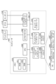
- the decision unit 222X performs an optimization calculation (ii) of the non-priority flow with objective function (ii) using the priority flow to be deleted and existing non-priority flows (all non-priority flows) as variables (step S201). Specifically, the decision unit 222X performs an optimization calculation (ii) of the non-priority flow with variables of all non-priority flows to minimize non-priority packets that do not satisfy QoS and to calculate a route for the non-priority flow that minimizes the maximum bandwidth of each link between each transfer device 40.
- the determination unit 222X determines whether or not there is a link whose bandwidth usage has decreased as a result of the calculation (step S202). When the determination unit 222X determines that there is a link whose bandwidth usage has decreased (step S202 "Yes"), it determines a route for the non-priority flow with the optimal variables of the optimization calculation (ii). In addition, the setting unit 223X sets the route for the non-priority flow with the optimal variables of the optimization calculation (ii) determined by the determination unit 222X to the transfer device 40 or the transmitting terminal 10 and transfers the flow (step S203).
- the determination unit 222X determines that there is no link whose bandwidth usage has decreased (step S202 "No"), it ends the process without determining the route for the non-priority flow with the optimal variables of the optimization calculation (ii) and rearranging it. In this way, the determination unit 222X may determine the route for the flow of non-priority packets only when at least one of the bandwidths of each link indicated by the bandwidth information acquired by the acquisition unit 221 is reduced.
- the determination unit 222X determines a route for the flow of non-priority packets based on the topology information acquired by the acquisition unit 221 and information on the forwarding delay of each forwarding device 40.
- the setting unit 223X sets the route for the flow of non-priority packets determined by the determination unit 222X to the forwarding device 40 or the transmitting terminal 10.
- the controller 200X can determine a route for non-priority flows that require large resources, and relocate the non-priority flows to that route, thereby reducing the amount of resources being used and freeing up those resources.
- TSN Time-Sensitive Networking
- the determination unit 222X determines a path for the flow of non-priority packets based on the topology information acquired by the acquisition unit 221 and information on the forwarding delay of each forwarding device 40.
- the setting unit 223X sets the path for the flow of non-priority packets determined by the determination unit 222X to the forwarding device 40 or the transmitting terminal 10.
- the controller 200X can determine a route for a non-priority flow that requires large resources, and relocate the non-priority flow to that route, thereby reducing the amount of resources being used and freeing up those resources.
- users of a TSN network rent a network dedicated to them from a network operator, they can reduce operating costs by reducing the amount of resources being used.
- the determination unit 222X determines the path for the flow of non-priority packets only when at least one of the bandwidths of the links indicated by the bandwidth information acquired by the acquisition unit 221 is reduced. As a result, the controller 200X determines the path for the flow of non-priority packets when the bandwidth of a link, which is one of the resources, is reduced, and therefore it is possible to reliably reduce the amount of resources being used.
- ⁇ program ⁇ It is also possible to create a program in which the processes executed by the controller 200 and the controller 200X described in the above embodiment are written in a language executable by a computer. In this case, the same effects as those of the above embodiment can be obtained by the computer executing the program. Furthermore, such a program may be recorded on a computer-readable recording medium, and the program recorded on the recording medium may be read and executed by a computer to realize the same processes as those of the above embodiment.
- FIG. 17 is a diagram showing an example of a computer that executes a program.
- the computer 1000 has, for example, a memory 1010, a CPU 1020, a hard disk drive interface 1030, a disk drive interface 1040, a serial port interface 1050, a video adapter 1060, and a network interface 1070. Each of these components is connected by a bus 1080.
- the memory 1010 includes a ROM (Read Only Memory) 1011 and a RAM 1012.
- the ROM 1011 stores a boot program such as a BIOS (Basic Input Output System).
- BIOS Basic Input Output System
- the hard disk drive interface 1030 is connected to a hard disk drive 1090.
- the disk drive interface 1040 is connected to a disk drive 1041.
- a removable storage medium such as a magnetic disk or optical disk is inserted into the disk drive 1041.
- the serial port interface 1050 is connected to, for example, a mouse 1110 and a keyboard 1120.
- the video adapter 1060 is connected to, for example, a display 1130.
- the hard disk drive 1090 stores, for example, an OS 1091, an application program 1092, a program module 1093, and program data 1094.
- Each table described in the above embodiment is stored, for example, in the hard disk drive 1090 or memory 1010.
- the control program is stored in the hard disk drive 1090, for example, as a program module in which instructions to be executed by the computer 1000 are written. Specifically, a program module 1093 in which each process executed by the controller 2000 described in the above embodiment is written is stored in the hard disk drive 1090.
- data used for information processing by the control program is stored as program data, for example, in the hard disk drive 1090.
- the CPU 1020 reads the program module 1093 and program data 1094 stored in the hard disk drive 1090 into the RAM 1012 as necessary, and executes each of the above procedures.
- the program module 1093 and program data 1094 related to the control program are not limited to being stored in the hard disk drive 1090, but may be stored in a removable storage medium, for example, and read by the CPU 1020 via the disk drive 1041 or the like.
- the program module 1093 and program data 1094 related to the control program may be stored in another computer connected via a network such as a LAN (Local Area Network) or a WAN (Wide Area Network), and read by the CPU 1020 via the network interface 1070.
- Control system 10 Transmission terminal 200, 200X Controller (control device) 210 Communication unit 220, 220X Control unit 221 Acquisition unit 222, 222X Determination unit 223, 223X Setting unit 224 Resource request unit 225 Topology update reception unit 230 Storage unit 231 NW topology storage unit 232 Accommodated flow storage unit 30 Orchestrator 40 Transfer device
Landscapes
- Engineering & Computer Science (AREA)
- Computer Networks & Wireless Communication (AREA)
- Signal Processing (AREA)
- Data Exchanges In Wide-Area Networks (AREA)
Abstract
Description
以下、第一の実施形態について説明する。第一の実施形態では、新規優先フローが追加される場合に、新規優先フローおよび非優先フローを最適化し、新規非優先フローが追加される場合に、全ての非優先フローを最適化する場合について説明する。
まず、図1を用いて、制御システム1の構成について説明する。図1は、第一の実施形態に係る制御システム1の構成の一例を表す図である。図1に示すシステムは、送信端末10と、コントローラ(制御装置)200と、オーケストレータ30と、転送装置40とを有する。なお、制御システム1は、複数の装置により実現されてもよい。また、制御システム1が複数の装置によって実現される場合には、制御システム1が有する各構成要素は、複数の装置にどのように振り分けられてもよい。
次に、図2を用いて、コントローラ200の構成について説明する。図2は、第一の実施形態に係るコントローラ200の構成の一例を示す図である。図2が示すように、コントローラ200は、通信部210と、制御部220と、記憶部230とを備える。これらの各部は、複数の装置が分散して保持してもよい。以下にこれら各部の処理を説明する。


次に、図3および図4を用いて、制御システム1による新規フローが追加された場合におけるフローの転送までの手順(フロー追加手順)を説明する。図3および図4は、第一の実施形態に係る制御システム1によるフロー追加手順の一例を示す図である。
次に、図5および図6を用いて、新規フローが追加された場合における経路設定によるフロー制御(フロー追加)の一例について説明する。図5および図6は、第一の実施形態に係る制御システム1によるフロー追加の一例を示す図である。
図7および図8を用いて新規フローが追加された場合における第一の実施形態に係るコントローラ200の経路設定によるフロー制御(フロー追加)の流れを説明する。図7および図8は第一の実施形態に係るフロー追加の流れの一例を示すフローチャートである。


上述の通り、第一の実施形態に係るコントローラ200は、取得部221と、決定部222と、設定部223とを有する。取得部221は、ネットワークの接続形態を示すトポロジ情報と、優先パケットおよび非優先パケットの転送を行う各転送装置40の転送遅延の情報とを取得する。決定部222は、新規優先パケットのフローが追加される場合に、取得部221により取得されたトポロジ情報と各転送装置40の転送遅延の情報とに基づいて、新規優先パケットのフローの経路および送信タイミングの少なくとも一方ならびに非優先パケットのフローの経路を決定する。また、決定部222は、新規非優先パケットのフローが追加される場合に、取得部221により取得されたトポロジ情報と各転送装置40の転送遅延の情報とに基づいて、新規非優先パケットのフローの経路および非優先パケットのフローの経路を決定する。設定部223は、決定部222により決定された新規優先パケットのフローの経路および送信タイミングの少なくとも一方ならびに非優先パケットのフローの経路、または、新規非優先パケットのフローの経路および非優先パケットのフローの経路を転送装置40または送信端末10に対して設定する。
以下、第二の実施形態について説明する。第二の実施形態では、優先フローや非優先フローが削除される場合に、非優先フローを最適化する場合について説明する。
まず、図9を用いて、第二の実施形態に係る制御システム1Xの構成について説明する。図9は、第二の実施形態に係る制御システム1Xの構成の一例を表す図である。図9に示すように、第二の実施形態に係る制御システム1Xは、図1の第一の実施形態に係る制御システム1と比較して、コントローラ200に代えてコントローラ200Xを有する。
次に、図10を用いて、コントローラ200Xの構成について説明する。図10は、第二の実施形態に係るコントローラ200Xの構成の一例を示す図である。図10が示すように、コントローラ200は、図2のコントローラ200と比較して、制御部220に代えて制御部220Xを有する。制御部220Xは、図2の制御部220と比較して、決定部222および設定部223に代えて決定部222Xおよび設定部223Xを有する。
次に、図11および12を用いて、第二の実施形態に係る制御システム1Xによる削除されたフローの転送までの手順(フローの削除手順)について説明する。図11および12は、第二の実施形態に係るフローの削除手順の一例を示す図である。
図13および14を用いて、フローが削除される場合の第二の実施形態に係る制御システム1Xの経路設定による経路設定によるフロー制御(フロー削除)の一例について説明する。図13および14は、第二の実施形態に係るフロー削除の一例を示す図である。
図15および16を用いて、フローが削除される場合の第二の実施形態に係るコントローラ200Xの経路設定によるフロー制御(フロー削除)の流れを説明する。図15および16は、第二の実施形態に係るフロー削除の流れの一例を示すフローチャートである。
上述の通り、第二の実施形態に係るコントローラ200Xにおいて、優先パケットのフローが削除される場合に、決定部222Xは、取得部221により取得されたトポロジ情報と各転送装置40の転送遅延の情報とに基づいて、非優先パケットのフローの経路を決定する。また、設定部223Xは、決定部222Xにより決定された非優先パケットのフローの経路を転送装置40または送信端末10に対して設定する。
上記実施形態において説明したコントローラ200およびコントローラ200Xが実行する処理をコンピュータが実行可能な言語で記述したプログラムを作成することもできる。この場合、コンピュータがプログラムを実行することにより、上記実施形態と同様の効果を得ることができる。さらに、かかるプログラムをコンピュータ読み取り可能な記録媒体に記録して、この記録媒体に記録されたプログラムをコンピュータに読み込ませて実行することにより上記実施形態と同様の処理を実現してもよい。
10 送信端末
200、200X コントローラ(制御装置)
210 通信部
220、220X 制御部
221 取得部
222、222X 決定部
223、223X 設定部
224 リソース要求部
225 トポロジ更新受付部
230 記憶部
231 NWトポロジ記憶部
232 収容フロー記憶部
30 オーケストレータ
40 転送装置
Claims (8)
- ネットワークの接続形態を示すトポロジ情報と、優先パケットおよび非優先パケットの転送を行う各転送装置の転送遅延の情報とを取得する取得部と、
新規優先パケットのフローが追加される場合に、前記取得部により取得されたトポロジ情報と各転送装置の転送遅延の情報とに基づいて、前記新規優先パケットのフローの経路および送信タイミングの少なくとも一方ならびに前記非優先パケットのフローの経路を決定し、新規非優先パケットのフローが追加される場合に、前記取得部により取得されたトポロジ情報と各転送装置の転送遅延の情報とに基づいて、前記新規非優先パケットのフローの経路および前記非優先パケットのフローの経路を決定する決定部と、
前記決定部により決定された前記新規優先パケットのフローの経路および送信タイミングの少なくとも一方ならびに前記非優先パケットのフローの経路、または、前記新規非優先パケットのフローの経路および前記非優先パケットのフローの経路を前記転送装置または送信端末に対して設定する設定部と
を有することを特徴とする制御装置。 - 前記優先パケットのフローが削除される場合に、前記決定部は、前記取得部により取得されたトポロジ情報と各転送装置の転送遅延の情報とに基づいて、前記非優先パケットのフローの経路を決定し、
前記設定部は、前記決定部により決定された前記非優先パケットのフローの経路を前記転送装置または前記送信端末に対して設定することを特徴とする請求項1に記載の制御装置。 - 前記非優先パケットのフローが削除される場合に、前記決定部は、前記取得部により取得されたトポロジ情報と各転送装置の転送遅延の情報とに基づいて、前記非優先パケットのフローの経路を決定し、
前記設定部は、前記決定部により決定された前記非優先パケットのフローの経路を前記転送装置または前記送信端末に対して設定することを特徴とする請求項1または2に記載の制御装置。 - 前記決定部により前記非優先パケットのフローの経路が決定された場合に、前記非優先パケットがQоS(Quality of Service)を満たさなければ、前記各転送装置間の各リンクのうち、前記各転送装置の最大流量を超える流量のリンクの帯域を増加させることを要求するリソース要求部をさらに有することを特徴とする請求項1に記載の制御装置。
- 前記取得部は、前記各転送装置間の各リンクの帯域の情報をさらに取得し、
前記決定部は、前記取得部により取得された前記帯域の情報にさらに基づいて、前記非優先パケットのフローの経路を決定することを特徴とする請求項1に記載の制御装置。 - 前記決定部は、前記取得部により取得された前記帯域の情報によって示される前記各リンクの帯域の少なくとも1つが減少する場合のみ、前記非優先パケットのフローの経路を決定することを特徴とする請求項5に記載の制御装置。
- ネットワークの接続形態を示すトポロジ情報と、優先パケットおよび非優先パケットの転送を行う各転送装置の転送遅延の情報とを取得する取得工程と、
新規優先パケットのフローが追加される場合に、前記取得工程により取得されたトポロジ情報と各転送装置の転送遅延の情報とに基づいて、前記新規優先パケットのフローの経路および送信タイミングの少なくとも一方ならびに前記非優先パケットのフローの経路を決定し、新規非優先パケットのフローが追加される場合に、前記取得工程により取得されたトポロジ情報と各転送装置の転送遅延の情報とに基づいて、前記新規非優先パケットのフローの経路および前記非優先パケットのフローの経路を決定する決定工程と、
前記決定工程により決定された前記新規優先パケットのフローの経路および送信タイミングの少なくとも一方ならびに前記非優先パケットのフローの経路、または、前記新規非優先パケットのフローの経路および前記非優先パケットのフローの経路を前記転送装置または送信端末に対して設定する設定工程と
を含むことを特徴とする制御方法。 - ネットワークの接続形態を示すトポロジ情報と、優先パケットおよび非優先パケットの転送を行う各転送装置の転送遅延の情報とを取得する取得ステップと、
新規優先パケットのフローが追加される場合に、前記取得ステップにより取得されたトポロジ情報と各転送装置の転送遅延の情報とに基づいて、前記新規優先パケットのフローの経路および送信タイミングの少なくとも一方ならびに前記非優先パケットのフローの経路を決定し、新規非優先パケットのフローが追加される場合に、前記取得ステップにより取得されたトポロジ情報と各転送装置の転送遅延の情報とに基づいて、前記新規非優先パケットのフローの経路および前記非優先パケットのフローの経路を決定する決定ステップと、
前記決定ステップにより決定された前記新規優先パケットのフローの経路および送信タイミングの少なくとも一方ならびに前記非優先パケットのフローの経路、または、前記新規非優先パケットのフローの経路および前記非優先パケットのフローの経路を前記転送装置または送信端末に対して設定する設定ステップと
をコンピュータに実行させることを特徴とする制御プログラム。
Priority Applications (2)
| Application Number | Priority Date | Filing Date | Title |
|---|---|---|---|
| PCT/JP2023/004661 WO2024166398A1 (ja) | 2023-02-10 | 2023-02-10 | 制御装置、制御方法および制御プログラム |
| JP2024576080A JPWO2024166398A1 (ja) | 2023-02-10 | 2023-02-10 |
Applications Claiming Priority (1)
| Application Number | Priority Date | Filing Date | Title |
|---|---|---|---|
| PCT/JP2023/004661 WO2024166398A1 (ja) | 2023-02-10 | 2023-02-10 | 制御装置、制御方法および制御プログラム |
Publications (1)
| Publication Number | Publication Date |
|---|---|
| WO2024166398A1 true WO2024166398A1 (ja) | 2024-08-15 |
Family
ID=92262779
Family Applications (1)
| Application Number | Title | Priority Date | Filing Date |
|---|---|---|---|
| PCT/JP2023/004661 Ceased WO2024166398A1 (ja) | 2023-02-10 | 2023-02-10 | 制御装置、制御方法および制御プログラム |
Country Status (2)
| Country | Link |
|---|---|
| JP (1) | JPWO2024166398A1 (ja) |
| WO (1) | WO2024166398A1 (ja) |
Citations (1)
| Publication number | Priority date | Publication date | Assignee | Title |
|---|---|---|---|---|
| JP2012253549A (ja) * | 2011-06-02 | 2012-12-20 | Nippon Telegr & Teleph Corp <Ntt> | マルチキャスト配信システム、帯域管理サーバ、および、マルチキャスト配信方法 |
-
2023
- 2023-02-10 JP JP2024576080A patent/JPWO2024166398A1/ja active Pending
- 2023-02-10 WO PCT/JP2023/004661 patent/WO2024166398A1/ja not_active Ceased
Patent Citations (1)
| Publication number | Priority date | Publication date | Assignee | Title |
|---|---|---|---|---|
| JP2012253549A (ja) * | 2011-06-02 | 2012-12-20 | Nippon Telegr & Teleph Corp <Ntt> | マルチキャスト配信システム、帯域管理サーバ、および、マルチキャスト配信方法 |
Non-Patent Citations (2)
| Title |
|---|
| AOKI, YOSHIKI ET AL.: "Method of accommodating priority flow in TSN for efficiency of network slice resources", IEICE TECHNICAL REPORT, vol. 122, no. 5 (NS2022-6), 8 April 2022 (2022-04-08), JP , pages 31 - 36, XP009556797, ISSN: 2432-6380 * |
| SHIBATA, NAOTAKA ET AL.: "Rerouting Technique of Low-priority traffic in Layer-2 Network for Multi-service Accommodation with Time Aware Shaper", IEICE TECHNICAL REPORT, vol. 120, no. 107 (CS2020-18), 9 July 2020 (2020-07-09), JP , pages 17 - 22, XP009556798, ISSN: 2432-6380 * |
Also Published As
| Publication number | Publication date |
|---|---|
| JPWO2024166398A1 (ja) | 2024-08-15 |
Similar Documents
| Publication | Publication Date | Title |
|---|---|---|
| JP7433479B2 (ja) | パケット転送方法、装置及び電子デバイス | |
| KR102693696B1 (ko) | 서비스 레벨 조절 방법, 장치, 디바이스, 및 시스템, 그리고 저장 매체 | |
| EP4152703A1 (en) | Network control method and device | |
| US8689049B2 (en) | Corrective actions based on probabilities | |
| CN107454017B (zh) | 一种云数据中心网络中混合数据流协同调度方法 | |
| CN118295937A (zh) | 用于网络接口卡的细粒度业务整形分流 | |
| US10536385B2 (en) | Output rates for virtual output queses | |
| US20230246966A1 (en) | Flexible load balancing on multipath networks | |
| WO2017096756A1 (en) | Method and apparatus for remote buffer status maintenance | |
| CN117714381B (zh) | Sdn数据中心网络下具有流感知的公平拥塞控制方法及设备 | |
| EP3485618B1 (en) | Device and method for managing end-to-end connections | |
| Qian et al. | A linux real-time packet scheduler for reliable static sdn routing | |
| EP3186927B1 (en) | Improved network utilization in policy-based networks | |
| CN120090974B (zh) | 基于数据与信用耦合的数据中心网络拥塞控制方法和装置 | |
| JP7687525B2 (ja) | 制御装置、制御方法および制御プログラム | |
| Liebeherr et al. | Buffer management and scheduling for enhanced differentiated services | |
| Samiayya et al. | An efficient congestion control in multimedia streaming using adaptive BRR and fuzzy butterfly optimization | |
| US11695644B2 (en) | Communication management apparatus and communication management method | |
| Hussain et al. | A lightweight fairness-driven AQM for regulating bandwidth utilization in best-effort routers | |
| CN119561911A (zh) | 保护大象流的主动拥塞控制方法和装置 | |
| WO2025148679A1 (zh) | 信用包重利用方法及设备 | |
| JP4977677B2 (ja) | エッジノードおよび帯域制御方法 | |
| Munir et al. | Scheduling network reservations with a flexible and reliable QoS mechanism in grids | |
| Kithinji et al. | A Survey of Packets Scheduling Congestion Control Algorithms in Internet Protocol Storage Area Networks | |
| JP2001230815A (ja) | パケット交換網における通信パケット長制御方式及びパケットスイッチ |
Legal Events
| Date | Code | Title | Description |
|---|---|---|---|
| 121 | Ep: the epo has been informed by wipo that ep was designated in this application |
Ref document number: 23921226 Country of ref document: EP Kind code of ref document: A1 |
|
| ENP | Entry into the national phase |
Ref document number: 2024576080 Country of ref document: JP Kind code of ref document: A |
|
| WWE | Wipo information: entry into national phase |
Ref document number: 2024576080 Country of ref document: JP |
|
| NENP | Non-entry into the national phase |
Ref country code: DE |
|
| 122 | Ep: pct application non-entry in european phase |
Ref document number: 23921226 Country of ref document: EP Kind code of ref document: A1 |