WO2024166279A1 - 電池収容装置、および電子機器 - Google Patents
電池収容装置、および電子機器 Download PDFInfo
- Publication number
- WO2024166279A1 WO2024166279A1 PCT/JP2023/004299 JP2023004299W WO2024166279A1 WO 2024166279 A1 WO2024166279 A1 WO 2024166279A1 JP 2023004299 W JP2023004299 W JP 2023004299W WO 2024166279 A1 WO2024166279 A1 WO 2024166279A1
- Authority
- WO
- WIPO (PCT)
- Prior art keywords
- positive electrode
- battery
- negative electrode
- terminal
- battery accommodating
- Prior art date
- Legal status (The legal status is an assumption and is not a legal conclusion. Google has not performed a legal analysis and makes no representation as to the accuracy of the status listed.)
- Ceased
Links
Images


Classifications
-
- H—ELECTRICITY
- H01—ELECTRIC ELEMENTS
- H01M—PROCESSES OR MEANS, e.g. BATTERIES, FOR THE DIRECT CONVERSION OF CHEMICAL ENERGY INTO ELECTRICAL ENERGY
- H01M50/00—Constructional details or processes of manufacture of the non-active parts of electrochemical cells other than fuel cells, e.g. hybrid cells
- H01M50/20—Mountings; Secondary casings or frames; Racks, modules or packs; Suspension devices; Shock absorbers; Transport or carrying devices; Holders
- H01M50/204—Racks, modules or packs for multiple batteries or multiple cells
- H01M50/207—Racks, modules or packs for multiple batteries or multiple cells characterised by their shape
- H01M50/213—Racks, modules or packs for multiple batteries or multiple cells characterised by their shape adapted for cells having curved cross-section, e.g. round or elliptic
-
- H—ELECTRICITY
- H01—ELECTRIC ELEMENTS
- H01M—PROCESSES OR MEANS, e.g. BATTERIES, FOR THE DIRECT CONVERSION OF CHEMICAL ENERGY INTO ELECTRICAL ENERGY
- H01M50/00—Constructional details or processes of manufacture of the non-active parts of electrochemical cells other than fuel cells, e.g. hybrid cells
- H01M50/50—Current conducting connections for cells or batteries
- H01M50/502—Interconnectors for connecting terminals of adjacent batteries; Interconnectors for connecting cells outside a battery casing
- H01M50/503—Interconnectors for connecting terminals of adjacent batteries; Interconnectors for connecting cells outside a battery casing characterised by the shape of the interconnectors
-
- H—ELECTRICITY
- H01—ELECTRIC ELEMENTS
- H01M—PROCESSES OR MEANS, e.g. BATTERIES, FOR THE DIRECT CONVERSION OF CHEMICAL ENERGY INTO ELECTRICAL ENERGY
- H01M50/00—Constructional details or processes of manufacture of the non-active parts of electrochemical cells other than fuel cells, e.g. hybrid cells
- H01M50/50—Current conducting connections for cells or batteries
- H01M50/502—Interconnectors for connecting terminals of adjacent batteries; Interconnectors for connecting cells outside a battery casing
- H01M50/509—Interconnectors for connecting terminals of adjacent batteries; Interconnectors for connecting cells outside a battery casing characterised by the type of connection, e.g. mixed connections
- H01M50/51—Connection only in series
-
- H—ELECTRICITY
- H01—ELECTRIC ELEMENTS
- H01M—PROCESSES OR MEANS, e.g. BATTERIES, FOR THE DIRECT CONVERSION OF CHEMICAL ENERGY INTO ELECTRICAL ENERGY
- H01M50/00—Constructional details or processes of manufacture of the non-active parts of electrochemical cells other than fuel cells, e.g. hybrid cells
- H01M50/50—Current conducting connections for cells or batteries
- H01M50/502—Interconnectors for connecting terminals of adjacent batteries; Interconnectors for connecting cells outside a battery casing
- H01M50/514—Methods for interconnecting adjacent batteries or cells
- H01M50/517—Methods for interconnecting adjacent batteries or cells by fixing means, e.g. screws, rivets or bolts
-
- H—ELECTRICITY
- H01—ELECTRIC ELEMENTS
- H01M—PROCESSES OR MEANS, e.g. BATTERIES, FOR THE DIRECT CONVERSION OF CHEMICAL ENERGY INTO ELECTRICAL ENERGY
- H01M50/00—Constructional details or processes of manufacture of the non-active parts of electrochemical cells other than fuel cells, e.g. hybrid cells
- H01M50/50—Current conducting connections for cells or batteries
- H01M50/572—Means for preventing undesired use or discharge
- H01M50/584—Means for preventing undesired use or discharge for preventing incorrect connections inside or outside the batteries
- H01M50/588—Means for preventing undesired use or discharge for preventing incorrect connections inside or outside the batteries outside the batteries, e.g. incorrect connections of terminals or busbars
-
- H—ELECTRICITY
- H01—ELECTRIC ELEMENTS
- H01M—PROCESSES OR MEANS, e.g. BATTERIES, FOR THE DIRECT CONVERSION OF CHEMICAL ENERGY INTO ELECTRICAL ENERGY
- H01M50/00—Constructional details or processes of manufacture of the non-active parts of electrochemical cells other than fuel cells, e.g. hybrid cells
- H01M50/50—Current conducting connections for cells or batteries
- H01M50/572—Means for preventing undesired use or discharge
- H01M50/584—Means for preventing undesired use or discharge for preventing incorrect connections inside or outside the batteries
- H01M50/59—Means for preventing undesired use or discharge for preventing incorrect connections inside or outside the batteries characterised by the protection means
- H01M50/597—Protection against reversal of polarity
-
- Y—GENERAL TAGGING OF NEW TECHNOLOGICAL DEVELOPMENTS; GENERAL TAGGING OF CROSS-SECTIONAL TECHNOLOGIES SPANNING OVER SEVERAL SECTIONS OF THE IPC; TECHNICAL SUBJECTS COVERED BY FORMER USPC CROSS-REFERENCE ART COLLECTIONS [XRACs] AND DIGESTS
- Y02—TECHNOLOGIES OR APPLICATIONS FOR MITIGATION OR ADAPTATION AGAINST CLIMATE CHANGE
- Y02E—REDUCTION OF GREENHOUSE GAS [GHG] EMISSIONS, RELATED TO ENERGY GENERATION, TRANSMISSION OR DISTRIBUTION
- Y02E60/00—Enabling technologies; Technologies with a potential or indirect contribution to GHG emissions mitigation
- Y02E60/10—Energy storage using batteries
Definitions
- This disclosure relates to a battery housing device and an electronic device.
- a battery storage device that connects multiple batteries in series by directly contacting the negative electrode of one battery with the positive electrode of a battery located next to the battery (see, for example, Patent Document 1).
- one of the objectives of the present disclosure is to provide a battery housing device having a structure that can prevent a battery from being housed upside down, and an electronic device equipped with such a battery housing device.
- One aspect of the battery accommodating device is a battery accommodating device capable of accommodating a plurality of batteries, each of which has a protruding positive electrode portion and a planar negative electrode portion provided on the opposite side of the positive electrode portion, the battery accommodating device comprising: a plurality of battery accommodating sections that open to a first side in a first direction and are capable of accommodating the plurality of batteries, a connection terminal capable of electrically connecting a pair of the batteries, and a terminal holding section that holds the connection terminal, the plurality of battery accommodating sections including at least a pair of battery accommodating sections aligned in a second direction intersecting the first direction, the terminal holding section being formed between the pair of battery accommodating sections in the second direction, the connection terminal having a positive terminal portion that can come into contact with the positive electrode portion of the battery accommodated in one of the pair of battery accommodating sections, and a negative terminal portion that can come into contact with the negative electrode portion of the battery accommodated in the other of the pair of battery accommodating sections, the negative terminal portion being in the form of a coil spring that
- One embodiment of an electronic device includes the battery accommodating device described above and an electronic component electrically connected to the battery accommodating device.
- the present disclosure makes it possible to prevent batteries from being placed in the battery accommodating device in the wrong direction.
- FIG. 1 is a perspective view showing an electronic device according to an embodiment.
- 1 is an exploded perspective view showing an electronic device according to an embodiment.
- FIG. 2 is a perspective view showing a battery accommodating device according to the embodiment, illustrating a state in which a plurality of batteries are accommodated.
- FIG. 2 is a perspective view showing the battery accommodating device according to the embodiment, illustrating a state in which a plurality of batteries are not accommodated.
- 4 is a perspective view showing a first terminal holding portion and a connection terminal in the embodiment.
- FIG. FIG. 2 is a diagram showing a first terminal holding portion and a connection terminal in an embodiment as viewed from above, illustrating a state in which a battery is housed in a pair of first battery housing portions arranged on either side of the first terminal holding portion.
- FIG. 2 is a diagram showing a first terminal holding portion and a connection terminal in an embodiment as viewed from above, illustrating a state in which no battery is housed in a pair of first battery housing portions arranged on either side of the first terminal holding portion.
- FIG. 2 is a perspective view showing a first terminal holding portion in the embodiment. 4 is a top view of the first terminal holding portion in the embodiment.
- FIG. FIG. 2 is a perspective view showing a connection terminal in the embodiment.
- 11 is a perspective view showing a connection terminal in the embodiment, the connection terminal being viewed from an angle different from that in FIG. 10 .
- 11A and 11B are diagrams illustrating a case where a battery is inserted in an incorrect orientation into a battery accommodating device according to an embodiment.
- the drawings also show the X-axis, Y-axis, and Z-axis as appropriate.
- the direction along the X-axis is called the "front-rear direction X”
- the direction along the Y-axis is called the “left-right direction Y”
- the direction along the Z-axis is called the "up-down direction Z”.
- the front-rear direction X, left-right direction Y, and up-down direction Z are mutually perpendicular directions.
- the side of the up-down direction Z toward which the Z-axis arrow points (+Z side) is the upper side
- the opposite side of the up-down direction Z to the side toward which the Z-axis arrow points (-Z side) is the lower side.
- the side of the front-rear direction X toward which the X-axis arrow points (+X side) is the front side
- the opposite side of the front-rear direction X to the side toward which the X-axis arrow points (-X side) is the rear side.
- the side of the left-right direction Y toward which the Y-axis arrow points (+Y side) is the left side
- the opposite side of the left-right direction Y to the side toward which the Y-axis arrow points (-Y side) is the right side.
- the terms up-down, front-back, and left-right are simply names used to describe the relative positional relationships of the various parts, and the actual positional relationships may be other than those indicated by these names.
- the up-down direction Z corresponds to the "first direction”
- the left-right direction Y corresponds to the "second direction”
- the front-back direction X corresponds to the "third direction”.
- the upper side corresponds to the "first side” of the first direction
- the lower side corresponds to the "second side" of the first direction.
- FIG. 1 is a perspective view showing electronic device 100 in this embodiment.
- FIG. 2 is an exploded perspective view showing electronic device 100 in this embodiment.
- Electronic device 100 shown in FIGS. 1 and 2 may be any type of electronic device, and may be, for example, a remote controller for operating a home appliance such as an air conditioner, or an electronic device for checking the operation of devices installed in an air conditioner.
- electronic device 100 has a generally rectangular parallelepiped shape extending in the left-right direction Y.
- electronic device 100 When viewed in the up-down direction Z, electronic device 100 has a generally rectangular shape that is long in the left-right direction Y, with a pair of sides extending in the front-back direction X and a pair of sides extending in the left-right direction Y.
- the dimension of electronic device 100 in the up-down direction Z is smaller than the dimension of electronic device 100 in the front-back direction X.
- the electronic device 100 includes a case 10, an electronic component 20, and a battery accommodating device 30.
- the case 10 accommodates the electronic component 20 and the battery accommodating device 30 inside.
- the case 10 is made of, for example, resin.
- the case 10 has a box-shaped case body 11 that opens to the top, and a lid body 12 fixed to the top of the case body 11.
- the case body 11 has a bottom wall portion 11a located on the bottom side, and a peripheral wall portion 11b that protrudes to the top from the outer periphery of the bottom wall portion 11a.
- the bottom wall portion 11a has a plate surface facing the vertical direction Z and is a substantially rectangular plate that is long in the left-right direction Y.
- the lid body 12 closes the upper opening of the case body 11.
- the lid body 12 is removably fixed to the case body 11 by four bolts.
- the electronic component 20 is a printed wiring board whose plate surface faces the vertical direction Z.
- the electronic component 20 is housed inside the case 10 on the left side (+Y side) and rear side (-X side).
- the battery accommodating device 30 is a device capable of accommodating multiple batteries 80. Power is supplied to the electronic component 20 by the multiple batteries 80 accommodated in the battery accommodating device 30.
- the battery accommodating device 30 accommodates multiple batteries 80 with the multiple batteries 80 connected in series. In this embodiment, the battery accommodating device 30 accommodates six batteries 80.
- the battery 80 is a dry cell.
- the battery 80 is, for example, an AA dry cell.
- the battery 80 may be a dry cell other than an AA dry cell.
- the battery 80 has a positive electrode portion 81, a negative electrode portion 82, and a battery body portion 83.
- the battery body portion 83 is cylindrical and extends in one direction.
- the positive electrode portion 81 is formed at one end of the battery body portion 83.
- the positive electrode portion 81 protrudes from one end of the battery body portion 83 in the direction in which the battery body portion 83 extends.
- the positive electrode portion 81 is cylindrical and arranged coaxially with the battery body portion 83.
- the outer diameter of the positive electrode portion 81 is smaller than the outer diameter of the battery body portion 83.
- the negative electrode portion 82 is formed at the other end of the battery body portion 83.
- the negative electrode portion 82 is provided on the opposite side to the positive electrode portion 81.
- the negative electrode portion 82 is formed in a planar shape on the surface of the other end side of the battery body portion 83.
- Each battery 80 is accommodated in the battery accommodating device 30 in a position in which the battery main body 83 extends in the left-right direction Y.
- the multiple batteries 80 include three batteries 80 accommodated in a position in which the positive electrode portion 81 is located on the right side (-Y side) and the negative electrode portion 82 is located on the left side (+Y side), and three batteries 80 accommodated in a position in which the positive electrode portion 81 is located on the left side and the negative electrode portion 82 is located on the right side. Note that the following explanation of the batteries 80 will be given for the case in which the batteries 80 are accommodated in the battery accommodating device 30, unless otherwise specified.
- the battery accommodating device 30 is located in the front (+X side) part of the inside of the case 10.
- the battery accommodating device 30 is formed in the front part of the case main body 11.
- the battery accommodating device 30 extends in the left-right direction Y.
- the battery accommodating device 30 includes an accommodating main body portion 40, a connection terminal 50, a positive electrode member 61, a negative electrode member 62, and a connection member 63.
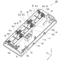
- FIG. 3 is a perspective view of the battery accommodating device 30, showing a state in which multiple batteries 80 are accommodated.
- FIG. 4 is a perspective view of the battery accommodating device 30, showing a state in which multiple batteries 80 are not accommodated.
- the accommodating main body 40 is integrally molded with the case body 11.
- the accommodating main body 40 is formed in the front (+X side) portion of the case body 11.
- the accommodating main body 40 is made of, for example, resin.
- the accommodating main body 40 has multiple battery accommodating sections 41 and a terminal holding section 70.
- the multiple battery storage sections 41 are each capable of storing multiple batteries 80.
- "batteries 80 are stored in the battery storage sections 41” means that the batteries 80 are held in the battery storage sections 41 with at least a portion of the batteries 80 positioned within the battery storage sections 41.
- a total of six battery accommodating sections 41 are provided, including three first battery accommodating sections 41a aligned in the left-right direction Y and three second battery accommodating sections 41b aligned in the left-right direction Y.
- the three second battery accommodating sections 41b are arranged adjacent to each other on the rear side (-X side) of the three first battery accommodating sections 41a.
- the first battery accommodating section 41a accommodates the battery 80 with the positive electrode section 81 located on the right side (-Y side) and the negative electrode section 82 located on the left side (+Y side).
- the second battery accommodating section 41b accommodates the battery 80 with the positive electrode section 81 located on the left side and the negative electrode section 82 located on the right side.
- the first battery accommodating section 41a and the second battery accommodating section 41b have substantially the same configuration, except that the orientation of the accommodated battery 80 is opposite.
- the first battery accommodating section 41a will be explained as a representative of the first battery accommodating section 41a and the second battery accommodating section 41b, and explanations of the second battery accommodating section 41b with similar configurations may be omitted.
- the first battery accommodating section 41a opens to the upper side in the vertical direction Z.
- the first battery accommodating section 41a is elongated in the horizontal direction Y and has a generally rectangular box shape that opens to the upper side.
- the first battery accommodating section 41a has a bottom wall section 42 located on the lower side, and a front wall section 43 and a rear wall section 44 that protrude upward from both edges of the bottom wall section 42 in the front-rear direction X.
- the bottom wall 42 is formed by a part of the bottom wall 11a of the case body 11.
- the bottom wall 42 has a generally rectangular shape that is long in the left-right direction Y.
- the front wall 43 protrudes upward from the front (+X side) edge of the bottom wall 42.
- the rear wall 44 protrudes upward from the rear (-X side) edge of the bottom wall 42.
- the front wall 43 of the first battery accommodating section 41a is formed by a part of the front portion of the peripheral wall 11b of the case body 11.
- the rear wall 44 of the first battery accommodating section 41a is shared with the front wall 43 of the second battery accommodating section 41b.
- the terminal holding portion 70 is formed between a pair of battery accommodating portions 41 aligned in the left-right direction Y.
- the terminal holding portion 70 includes a first terminal holding portion 70a formed between the first battery accommodating portions 41a aligned in the left-right direction Y, and a second terminal holding portion 70b formed between the second battery accommodating portions 41b aligned in the left-right direction Y.
- two first terminal holding portions 70a and two second terminal holding portions 70b are provided.
- Each first terminal holding portion 70a is disposed adjacent to the front side (+X side) of each second terminal holding portion 70b.
- the first terminal holding portion 70a and the second terminal holding portion 70b have the same structure, except that they are inverted relative to each other in the front-to-back direction X and the left-to-right direction Y.
- the first terminal holding portion 70a and the second terminal holding portion 70b each hold a connection terminal 50.
- the connection terminal 50 held by the first terminal holding portion 70a and the connection terminal 50 held by the second terminal holding portion 70b are each held by each terminal holding portion 70 in an orientation in which the orientations in the left-to-right direction Y are opposite to each other.
- the first terminal holding portion 70a will be described as a representative of the first terminal holding portion 70a and the second terminal holding portion 70b, and a description of the second terminal holding portion 70b may be omitted as it has a similar configuration except that it has an inverted structure in the front-back direction X and the left-right direction Y.
- FIG. 5 is a perspective view showing the first terminal holding portion 70a and the connection terminal 50.
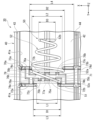
- FIG. 6 is a view of the first terminal holding portion 70a and the connection terminal 50 from above, showing a state in which a battery 80 is accommodated in a pair of first battery accommodating portions 41a arranged on either side of the first terminal holding portion 70a.
- FIG. 7 is a view of the first terminal holding portion 70a and the connection terminal 50 from above, showing a state in which a battery 80 is not accommodated in a pair of first battery accommodating portions 41a arranged on either side of the first terminal holding portion 70a.
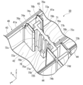
- FIG. 8 is a perspective view showing the first terminal holding portion 70a.
- FIG. 9 is a view of the first terminal holding portion 70a from above.
- the first terminal holding portion 70a holds the connection terminal 50.
- the connection terminal 50 is held by fitting a part of the connection terminal 50 from above into the first terminal holding portion 70a.
- the connection terminal 50 can be detached from the connection terminal 50 by being pulled upward.
- the first battery accommodating portion 41a located on the left side (+Y side) of the first terminal holding portion 70a corresponds to "one battery accommodating portion” of the pair of battery accommodating portions 41 aligned in the left-right direction Y.
- the first battery accommodating portion 41a located on the right side (-Y side) of the first terminal holding portion 70a corresponds to "the other battery accommodating portion” of the pair of battery accommodating portions 41 aligned in the left-right direction Y.
- the first battery accommodating portion 41a located on the left side of the first terminal holding portion 70a may be simply referred to as the "left first battery accommodating portion 41a,” and the first battery accommodating portion 41a located on the right side of the first terminal holding portion 70a may be simply referred to as the "right first battery accommodating portion 41a.”
- the first terminal holding portion 70a has a bottom wall portion 79, a partition portion 71, a pair of first walls 72a, 72b, a pair of second walls 73a, 73b, a pair of first connecting walls 74a, 74b, a second connecting wall portion 74c, and a third connecting wall portion 74d.
- the partition portion 71, the pair of first walls 72a, 72b, the pair of second walls 73a, 73b, the pair of first connecting walls 74a, 74b, the second connecting wall portion 74c, and the third connecting wall portion 74d protrude upward from the bottom wall portion 79.
- the bottom wall portion 79 is the lower wall portion of the walls constituting the first terminal holding portion 70a.
- the bottom wall portion 79 is formed by a part of the bottom wall portion 11a of the case body 11.
- the bottom wall portion 79 has a generally rectangular shape that is long in the front-rear direction X.
- the partition wall portion 71 protrudes upward from the center of the bottom wall portion 79 in the left-right direction Y.
- the partition wall portion 71 extends in the front-rear direction X.
- a gap is provided on each side of the partition wall portion 71 in the front-rear direction X.
- the partition wall portion 71 is located between the positive electrode terminal portion 51 (described later) and the negative electrode terminal portion 52 (described later) in the left-right direction Y.
- the pair of first walls 72a, 72b are located to the left (+Y side) of the partition wall 71.
- the pair of first walls 72a, 72b are arranged with a gap in the front-rear direction X.
- the upper ends of the pair of first walls 72a, 72b are located above the upper end of the partition wall 71.
- the pair of first walls 72a, 72b form a wall on the right side (-Y side) of the left first battery housing section 41a.
- the first wall 72a protrudes rearward (-X side) from the front wall 43 of the left first battery housing section 41a.
- the first wall 72b protrudes frontward (+X side) from the rear wall 44 of the left first battery housing section 41a.
- a first opening 72c is formed between the pair of first walls 72a, 72b in the front-rear direction X.
- the first opening 72c opens to the left (+Y side) and into the left first battery housing section 41a.
- the first opening 72c connects the inside of the left first battery housing section 41a to the inside of the positive electrode housing section 78a, which will be described later.
- the dimension L1 in the front-rear direction X of the first opening 72c is equal to or greater than the dimension in the front-rear direction X of the positive electrode portion 81 of the battery 80, i.e., the outer diameter D4. More specifically, the dimension L1 in the front-rear direction X of the first opening 72c is greater than the outer diameter D4 of the positive electrode portion 81.
- the dimension L1 in the front-rear direction X of the first opening 72c is smaller than the dimension in the front-rear direction X of the end of the battery 80 on the side (+Y side) where the negative electrode portion 82 is formed, i.e., the outer diameter D5.
- the outer diameter D5 is the outer diameter of the battery main body portion 83.
- the pair of second walls 73a, 73b are located to the right (-Y side) of the partition wall 71.
- the pair of second walls 73a, 73b are arranged with a gap in the front-rear direction X.
- the gap between the pair of second walls 73a, 73b in the front-rear direction X is larger than the gap between the pair of first walls 72a, 72b in the front-rear direction X.
- the second wall 73a is arranged to face the first wall 72a with a gap on the right side.
- the first wall 72a and the second wall 73a are arranged to sandwich the front (+X side) end of the partition wall 71 in the left-right direction Y.
- the second wall 73b is arranged to face the first wall 72b with a gap on the right side.
- the first wall 72b and the second wall 73b are arranged to sandwich the rear (-X side) end of the partition wall 71 in the left-right direction Y.
- the upper ends of the pair of second walls 73a, 73b are located above the upper end of the partition wall 71.
- the pair of second walls 73a, 73b form a wall on the left side (+Y side) of the right side (-Y side) of the first battery accommodating section 41a.
- the second wall 73a protrudes rearward (-X side) from the front wall 43 of the right side first battery accommodating section 41a.
- the second wall 73b protrudes frontward (+X side) from the rear wall 44 of the right side first battery accommodating section 41a.
- a second opening 73c is formed between the pair of second wall portions 73a, 73b in the front-rear direction X.
- the second opening 73c opens to the right side (-Y side) and opens into the right first battery housing portion 41a.
- the second opening 73c connects the inside of the right first battery housing portion 41a to the inside of the negative electrode housing portion 78b described later.
- the dimension L2 of the second opening 73c in the front-rear direction X is larger than the dimension L1 of the first opening 72c in the front-rear direction X.
- the second opening 73c is formed at a position overlapping with the first opening 72c in the left-right direction Y. In this embodiment, the entire first opening 72c overlaps with the second opening 73c in the left-right direction Y.
- the second opening 73c protrudes on both sides of the first opening 72c in the front-rear direction X.
- the pair of first connecting walls 74a, 74b protrude from the partition wall 71 to the left (+Y side).
- the first connecting wall 74a protrudes from the front portion (+X side portion) of the partition wall 71 to the left and is connected to the first wall 72a.
- the first connecting wall 74a is located forward (+X side) of the rear (-X side) end of the first wall 72a and rearward of the front end of the partition wall 71.
- the first connecting wall 74b protrudes from the rear end of the partition wall 71 to the left and is connected to the first wall 72b.
- the first connecting wall 74b is located rearward of the front end of the first wall 72b.
- the upper ends of the first connecting walls 74a, 74b are located at the same position in the vertical direction Z as the upper end of the partition wall 71.
- the second connecting wall portion 74c protrudes to the right side (-Y side) from the partition portion 71. More specifically, the second connecting wall portion 74c protrudes to the right side from the front (+X side) end of the partition portion 71 and is connected to the second wall portion 73a.
- the second connecting wall portion 74c is located forward of the rear (-X side) end of the second wall portion 73a.
- the upper end of the second connecting wall portion 74c is located at the same position in the vertical direction Z as the upper end of the partition portion 71.
- the third connection wall 74d protrudes upward from the rear end (-X side) of the bottom wall 79.
- the third connection wall 74d connects the rear wall 44 of the first battery accommodating portion 41a on the left side (+Y side) to the rear wall 44 of the first battery accommodating portion 41a on the right side (-Y side) in the left-right direction Y.
- the third connection wall 74d in the first terminal holding portion 70a is shared with the third connection wall 74d in the second terminal holding portion 70b adjacent to the rear side of the first terminal holding portion 70a.
- the third connection wall 74d is disposed opposite the rear side of the partition portion 71 with a gap therebetween.
- the upper end of the third connection wall 74d is disposed at the same position in the up-down direction Z as the upper end of the partition portion 71.
- the first terminal holding portion 70a has a positive electrode housing portion 78a that houses at least a portion of the positive electrode terminal portion 51 described later, and a negative electrode housing portion 78b that houses at least a portion of the negative electrode terminal portion 52 described later.
- the positive electrode housing portion 78a houses the entire positive electrode terminal portion 51.
- the negative electrode housing portion 78b houses only a portion of the negative electrode terminal portion 52.
- the positive electrode housing portion 78a is formed in the left portion (+Y side portion) of the first terminal holding portion 70a.
- the negative electrode housing portion 78b is formed in the right portion (-Y side portion) of the first terminal holding portion 70a.
- the positive electrode housing 78a is formed by the partition 71, a pair of first walls 72a, 72b, a pair of first connecting walls 74a, 74b, and a bottom wall 79.
- the interior of the positive electrode housing 78a is formed by an inner space surrounded by the partition 71, the pair of first walls 72a, 72b, the pair of first connecting walls 74a, 74b, and the bottom wall 79, and is open to the upper side.
- the positive electrode housing 78a has the first opening 72c described above.
- the interior of the positive electrode housing 78a is connected in the left-right direction Y to the interior of the first battery housing 41a on the left side (+Y side) via the first opening 72c.
- the negative electrode housing portion 78b is formed by the partition portion 71, the pair of second walls 73a, 73b, the second connecting wall portion 74c, the third connecting wall portion 74d, and the bottom wall portion 79.
- the interior of the negative electrode housing portion 78b is formed by an inner space surrounded by the partition portion 71, the pair of second walls 73a, 73b, the second connecting wall portion 74c, the third connecting wall portion 74d, and the bottom wall portion 79, and is open to the upper side.
- the negative electrode housing portion 78b has the second opening 73c described above.
- the interior of the negative electrode housing portion 78b is connected in the left-right direction Y to the interior of the first battery housing portion 41a on the right side (-Y side) via the second opening 73c.
- the dimension L3 in the front-rear direction X inside the positive electrode accommodating portion 78a and the dimension L4 in the front-rear direction X inside the negative electrode accommodating portion 78b are different from each other.
- the dimension L3 in the front-rear direction X inside the positive electrode accommodating portion 78a is the distance in the front-rear direction X between the first connecting wall portion 74a and the first connecting wall portion 74b.
- the dimension L4 in the front-rear direction X inside the negative electrode accommodating portion 78b is the distance in the front-rear direction X between the second connecting wall portion 74c and the third connecting wall portion 74d.
- the dimension L3 in the front-rear direction X inside the positive electrode accommodating portion 78a is smaller than the dimension L4 in the front-rear direction X inside the negative electrode accommodating portion 78b.
- the dimension L3 in the front-rear direction X inside the positive electrode accommodating portion 78a is larger than the dimension L1 in the front-rear direction X of the first opening 72c and smaller than the dimension L2 in the front-rear direction X of the second opening 73c.
- the dimension L4 in the front-to-rear direction X inside the negative electrode housing portion 78b is greater than the dimension L2 in the front-to-rear direction X of the second opening 73c.
- the first terminal holding portion 70a has first positive electrode support portions 75a, 75b and a second positive electrode support portion 77a. As shown in Figs. 6 and 7, the first positive electrode support portions 75a, 75b protrude in the left-right direction Y from the partition portion 71 toward the positive electrode terminal portion 51 described below. In this embodiment, the first positive electrode support portions 75a, 75b protrude from the partition portion 71 to the left (+Y side).
- the first positive electrode support portions 75a, 75b extend downward from the upper end of the partition wall portion 71 and connect to the bottom wall portion 79.
- the first positive electrode support portions 75a, 75b are located inside the positive electrode accommodating portion 78a, between the pair of first connecting walls 74a, 74b in the front-to-rear direction X.
- the first positive electrode support portions 75a, 75b are arranged at positions overlapping with the first opening 72c when viewed in the left-right direction Y.
- the first positive electrode support portions 75a, 75b are arranged facing the right side (-Y side) of the first opening 72c.
- the first positive electrode support portion 75a is disposed at a position overlapping with the center of the first opening 72c in the front-rear direction X when viewed in the left-right direction Y.
- the first positive electrode support portion 75b is provided in a pair, sandwiching the first positive electrode support portion 75a in the front-rear direction X.
- the dimension of each first positive electrode support portion 75b in the front-rear direction X is smaller than the dimension of the first positive electrode support portion 75a in the front-rear direction X.
- the second positive electrode support portion 77a protrudes to the left side (+Y side) from the lower end of the first positive electrode support portion 75a.
- the lower end of the second positive electrode support portion 77a is connected to the bottom wall portion 79.
- the second positive electrode support portion 77a is located within the positive electrode housing portion 78a. As shown in FIG. 7, the second positive electrode support portion 77a is disposed below the positive electrode terminal portion 51, which will be described later. In other words, the second positive electrode support portion 77a is disposed opposite the lower side of the positive electrode terminal portion 51.
- the first terminal holding portion 70a has first negative electrode support portions 76a, 76b and a second negative electrode support portion 77b.
- the first negative electrode support portions 76a, 76b protrude in the left-right direction Y from the partition portion 71 toward the negative electrode terminal portion 52 described below.
- the first negative electrode support portions 76a, 76b protrude to the right (-Y side) from the partition portion 71.
- the first negative electrode support parts 76a, 76b extend downward from the upper end of the partition wall part 71 and connect to the bottom wall part 79.
- the first negative electrode support parts 76a, 76b are located inside the negative electrode accommodating part 78b, between the second connecting wall part 74c and the third connecting wall part 74d in the front-rear direction X.
- the first negative electrode support parts 76a, 76b are arranged at a position overlapping with the second opening part 73c when viewed in the left-right direction Y.
- the first negative electrode support parts 76a, 76b are arranged facing the left side (+Y side) of the second opening part 73c.
- the first negative electrode support portion 76a is arranged at a position overlapping with the center of the second opening 73c in the front-rear direction X when viewed in the left-right direction Y.
- the first negative electrode support portion 76a is arranged at the same position as the first positive electrode support portion 75a in the front-rear direction X.
- the first negative electrode support portion 76a is arranged to sandwich the partition portion 71 in the left-right direction Y between it and the first positive electrode support portion 75a.
- a pair of first negative electrode support portions 76b are provided to sandwich the first negative electrode support portion 76a in the front-rear direction X.
- each first negative electrode support portion 76b in the front-rear direction X is smaller than the dimension of the first negative electrode support portion 76a in the front-rear direction X.
- the distance between the pair of first negative electrode support portions 76a, 76b in the front-rear direction X is larger than the distance between the pair of first positive electrode support portions 75a, 75b in the front-rear direction X.
- the distance in the front-rear direction X between the first negative electrode support part 76a and the first negative electrode support part 76b is greater than the distance in the front-rear direction X between the first positive electrode support part 75a and the first positive electrode support part 75b.
- the second negative electrode support part 77b protrudes to the right side (-Y side) from the lower end of the first negative electrode support part 76a.
- the lower end of the second negative electrode support part 77b is connected to the bottom wall part 79.
- the second negative electrode support part 77b is located inside the negative electrode accommodating part 78b.
- the second negative electrode support part 77b is disposed below the negative electrode terminal part 52, which will be described later. In other words, the second negative electrode support part 77b is disposed opposite the lower side of the negative electrode terminal part 52.
- connection terminal 50 is formed from a wire.
- the connection terminal 50 is made by shaping a single metal wire by bending or other processing.
- the cross-sectional shape of the wire constituting the connection terminal 50 is circular.
- the orientation of the connection terminal 50 in the left-right direction Y differs when it is held by the first terminal holding portion 70a and when it is held by the second terminal holding portion 70b.
- the connection terminal 50 the relative positional relationship and the like will be described for the connection terminal 50 held by the first terminal holding portion 70a.
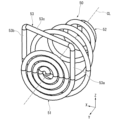
- FIG. 10 is a perspective view of the connection terminal 50.
- FIG. 11 is a perspective view of the connection terminal 50, from an angle different from that of FIG. 10.
- the connection terminal 50 has a positive electrode terminal portion 51, a negative electrode terminal portion 52, and a connecting portion 53.
- the positive electrode terminal portion 51 and the negative electrode terminal portion 52 face each other with a gap therebetween in the left-right direction Y.
- the positive electrode terminal portion 51 and the negative electrode terminal portion 52 are connected to each other by the connecting portion 53.
- the positive electrode terminal 51 is located to the left (+Y side) of the negative electrode terminal 52.
- the positive electrode terminal 51 is formed by winding a wire in a spiral shape.
- the wire forming the connection terminal 50 is wound in a spiral shape from one end in a direction in which the outer diameter increases, so that the positive electrode terminal 51 is formed into a roughly circular plate shape centered on an imaginary center line CL as a whole.
- the imaginary center line CL is an imaginary line that extends in the left-right direction Y.
- the positive electrode terminal 51 is inserted from above into the positive electrode housing 78a and held by the first terminal holder 70a.
- the dimension of the positive electrode terminal 51 in the front-rear direction X i.e., the outer diameter D1 of the positive electrode terminal 51, is approximately the same as the dimension L3 in the front-rear direction X inside the positive electrode housing 78a, and is slightly smaller than the dimension L3.
- the outer diameter D1 of the positive electrode terminal 51 is larger than the dimension L1 in the front-rear direction X of the first opening 72c. Both ends of the positive electrode terminal 51 in the front-rear direction X are respectively disposed between the pair of first walls 72a, 72b and the partition wall 71 in the left-right direction Y.
- the portion of the positive electrode terminal 51 other than both ends in the front-rear direction X is disposed facing the right side (-Y side) of the first opening 72c. As a result, the positive electrode terminal 51 is exposed through the first opening 72c into the first battery housing 41a on the left side (+Y side).
- the dimension of the positive electrode terminal portion 51 in the left-right direction Y is approximately the same as the distance in the left-right direction Y between the first positive electrode support portions 75a, 75b and the pair of first wall portions 72a, 72b, and is slightly smaller than that distance.
- the positive electrode terminal portion 51 may be in contact with one of the first positive electrode support portions 75a, 75b and the pair of first wall portions 72a, 72b, or may be arranged opposite both the first positive electrode support portions 75a, 75b and the pair of first wall portions 72a, 72b with a gap therebetween.
- the lower end portion at the center of the positive electrode terminal portion 51 in the front-rear direction X is arranged opposite the upper side of the second positive electrode support portion 77a with a gap therebetween.
- the positive electrode terminal portion 51 can come into contact with the positive electrode portion 81 of the battery 80 housed in the first battery housing portion 41a on the left side (+Y side). Specifically, when the battery 80 is housed in the first battery housing portion 41a on the left side, the positive electrode portion 81 is inserted into the first opening 72c, and the right side (-Y side) end of the positive electrode portion 81 comes into contact from the left side with the positive electrode terminal portion 51 housed in the positive electrode housing portion 78a. In other words, the positive electrode portion 81 comes into contact with the positive electrode terminal portion 51 in the positive electrode housing portion 78a by being passed through the first opening 72c.
- the negative electrode terminal portion 52 is in the form of a coil spring that is elastically deformable in the left-right direction Y.
- the negative electrode terminal portion 52 is formed by winding a wire in a spiral shape in which the outer diameter decreases with increasing distance from the positive electrode terminal portion 51 in the left-right direction Y.
- the outer diameter of the negative electrode terminal portion 52 decreases toward the right side (-Y side).
- the spirally extending negative electrode terminal portion 52 is disposed coaxially with the substantially disc-shaped positive electrode terminal portion 51.
- the negative electrode terminal portion 52 extends in a spiral shape centered on the imaginary center line CL. In this way, the shape of the positive electrode terminal portion 51 and the shape of the negative electrode terminal portion 52 are different from each other.
- the side of the negative terminal 52 closest to the positive terminal 51 i.e., the end on the left side (+Y side)
- the large diameter section 52a which has the largest outer diameter of the negative terminal 52.
- the outer diameter D2 of the large diameter section 52a is larger than the outer diameter D1 of the positive terminal 51.
- the side of the negative terminal 52 farthest from the positive terminal 51 i.e., the end on the right side (-Y side)
- the outer diameter D3 of the small diameter section 52b is smaller than the outer diameter D1 of the positive terminal 51.
- the negative terminal portion 52 is held by the first terminal holding portion 70a with the large diameter portion 52a inserted from above into the negative electrode housing portion 78b.
- the negative terminal portion 52 passes through the second opening 73c in the left-right direction Y.
- the right portion (-Y side portion) of the negative terminal portion 52 is located in the right-side first battery housing portion 41a.
- the negative terminal portion 52 passes through the second opening 73c and protrudes into the right-side first battery housing portion 41a.
- the negative terminal portion 52 is exposed in the right-side first battery housing portion 41a.
- the outer diameter D2 of the large diameter portion 52a accommodated in the negative electrode accommodation portion 78b is smaller than the dimension L4 in the front-rear direction X inside the negative electrode accommodation portion 78b and is larger than the dimension L2 in the front-rear direction X of the second opening 73c.
- the outer diameter D2 of the large diameter portion 52a is larger than the dimension L3 in the front-rear direction X inside the positive electrode accommodation portion 78a.
- the dimension L3 in the front-rear direction X inside the positive electrode accommodation portion 78a is smaller than the dimension (outer diameter D2) in the front-rear direction X of the portion of the negative electrode terminal portion 52 accommodated in the negative electrode accommodation portion 78b, i.e., the large diameter portion 52a.
- Both ends of the large diameter portion 52a in the front-rear direction X are respectively disposed between the pair of second walls 73a, 73b and the partition portion 71 in the left-right direction Y.
- the dimension of the large diameter portion 52a in the left-right direction Y is approximately the same as, and slightly smaller than, the distance in the left-right direction Y between the first negative electrode support portions 76a, 76b and the pair of second wall portions 73a, 73b.
- the large diameter portion 52a may be in contact with either the first negative electrode support portions 76a, 76b or the pair of second wall portions 73a, 73b, or may be disposed opposite both the first negative electrode support portions 76a, 76b and the pair of second wall portions 73a, 73b with a gap therebetween.
- the lower end portion at the center of the large diameter portion 52a in the front-rear direction X is disposed opposite the upper side of the second negative electrode support portion 77b with a gap therebetween.
- the negative terminal portion 52 can come into contact with the negative electrode portion 82 of the battery 80 housed in the first battery housing portion 41a on the right side. Specifically, when a battery 80 is housed in the first battery housing portion 41a on the right side (-Y side), the negative terminal portion 52 is pushed to the left side (+Y side) by the negative electrode portion 82 and undergoes compressive elastic deformation. The negative terminal portion 52 comes into contact with the negative electrode portion 82 in the elastically deformed state.
- the positive electrode portion 81 of the battery 80 housed in the first battery housing portion 41a on the left side comes into contact with the positive terminal portion 51
- the negative electrode portion 82 of the battery 80 housed in the first battery housing portion 41a on the right side comes into contact with the negative terminal portion 52, so that the connection terminal 50 electrically connects the pair of batteries 80 to each other.
- the connecting portion 53 connects the positive electrode terminal portion 51 and the negative electrode terminal portion 52.
- the connecting portion 53 has a first extension portion 53a, a second extension portion 53b, and a third extension portion 53c.
- the first extension portion 53a extends upward from the rear (-X side) end of the positive electrode terminal portion 51. In this embodiment, the first extension portion 53a extends upward from the outer end of the spirally formed positive electrode terminal portion 51.
- the second extension portion 53b extends upward from the front (+X side) end of the negative electrode terminal portion 52. In this embodiment, the second extension portion 53b extends upward from the left (+Y side) end of the spirally formed negative electrode terminal portion 52.
- the third extension portion 53c connects the upper end of the first extension portion 53a and the upper end of the second extension portion 53b. As shown in FIG. 6, the third extension portion 53c extends in a direction that is inclined in the left-right direction Y with respect to the front-rear direction X. The third extension portion 53c is located on the right side (-Y side) as it approaches the front side (+X side). The third extension portion 53c is disposed facing the upper side of the partition portion 71. In this embodiment, the third extension portion 53c is in contact with the upper end of the partition portion 71.
- the connection terminal 50 is supported from below by the first terminal holding portion 70a as the third extension portion 53c is supported from below by the partition portion 71.
- the positive electrode member 61 and the negative electrode member 62 are held at the left end of the housing body 40.
- the positive electrode member 61 has a positive electrode portion 61a and a connection portion 61b.
- the positive electrode portion 61a is held at the left end of the second battery housing portion 41b located at the leftmost side (+Y side).
- the positive electrode portion 61a can come into contact with the positive electrode portion 81 of the battery 80 housed in the second battery housing portion 41b located at the leftmost side.
- the shape of the positive electrode portion 61a is the same as the shape of the positive electrode terminal portion 51 of the connection terminal 50.
- the connection portion 61b extends from the positive electrode portion 61a and is electrically connected to the electronic component 20.
- the negative electrode member 62 has a negative electrode portion 62a and a connection portion 62b.
- the negative electrode portion 62a is held at the left end of the first battery housing portion 41a located on the leftmost side (+Y side).
- the negative electrode portion 62a can come into contact with the negative electrode portion 82 of the battery 80 housed in the first battery housing portion 41a located on the leftmost side.
- the shape of the negative electrode portion 62a is the same as the shape of the negative electrode terminal portion 52 of the connection terminal 50.
- the connection portion 62b extends from the negative electrode portion 62a and is electrically connected to the electronic component 20.
- the positive electrode member 61 and the negative electrode member 62 are electrically connected to the electronic component 20, so that the electronic component 20 is electrically connected to the battery housing device 30.
- the connection member 63 is held at the right end (-Y side) of the housing main body 40.
- the connection member 63 has a positive electrode portion 63a, a negative electrode portion 63b, and a connection portion 63c.
- the positive electrode portion 63a is held at the right end of the first battery housing portion 41a located at the rightmost position.
- the positive electrode portion 63a can contact the positive electrode portion 81 of the battery 80 housed in the first battery housing portion 41a located at the rightmost position.
- the shape of the positive electrode portion 63a is the same as the shape of the positive electrode terminal portion 51 of the connection terminal 50.
- the negative electrode portion 63b is held at the right end of the second battery housing portion 41b located at the rightmost position.
- the negative electrode portion 63b can contact the negative electrode portion 82 of the battery 80 housed in the second battery housing portion 41b located at the rightmost position.
- the shape of the negative electrode portion 63b is the same as the shape of the negative electrode terminal portion 52 of the connection terminal 50.
- the connection part 63c connects the positive electrode part 63a and the negative electrode part 63b.
- the three batteries 80 housed in the three first battery housing sections 41a arranged side by side in the left-right direction Y are connected in series by two connection terminals 50.
- the three batteries 80 housed in the three second battery housing sections 41b arranged side by side in the left-right direction Y are connected in series by two connection terminals 50.
- the positive electrode part 81 of the battery 80 housed in the first battery housing section 41a located on the rightmost side (-Y side) and the negative electrode part 82 of the battery 80 housed in the second battery housing section 41b located on the rightmost side are electrically connected via a connection member 63.
- the six batteries 80 housed in the six battery housing sections 41 are connected in series.
- the six batteries 80 connected in series are electrically connected to the electronic component 20 via the positive electrode member 61 and the negative electrode member 62. As a result, power is supplied from the six batteries 80 connected in series to the electronic component 20.
- the battery accommodating device 30 includes a plurality of battery accommodating sections 41 that open to the upper side in the vertical direction Z and can accommodate a plurality of batteries 80, a connection terminal 50 that can electrically connect a pair of batteries 80 to each other, and a terminal holding section 70 that holds the connection terminal 50.
- the plurality of battery accommodating sections 41 include at least a pair of battery accommodating sections 41 arranged in the left-right direction Y that intersects with the vertical direction Z.
- the terminal holding section 70 is formed between the pair of battery accommodating sections 41 in the left-right direction Y.
- the connection terminal 50 has a positive terminal section 51 that can come into contact with a positive electrode section 81 of a battery 80 accommodated in one of the pair of battery accommodating sections 41, and a negative terminal section 52 that can come into contact with a negative electrode section 82 of a battery 80 accommodated in the other of the pair of battery accommodating sections 41.
- the negative terminal section 52 is in the form of a coil spring that can be elastically deformed in the left-right direction Y.
- the shape of the positive terminal section 51 and the shape of the negative terminal section 52 are different from each other.
- connection terminals 50 having positive and negative terminal portions 51 and 52 that are different in shape an operator who stores multiple batteries 80 in the battery accommodating device 30 can easily recognize in which orientation the batteries 80 should be stored in each of a pair of battery accommodating portions 41 aligned in the left-right direction Y. This makes it possible to prevent the batteries 80 from being stored in the wrong orientation in the battery accommodating device 30. This makes it possible to prevent current from flowing in the wrong direction through the batteries 80, which would result in the batteries 80 being charged. This makes it possible to prevent pressure inside the batteries 80 from increasing, and to prevent problems such as leakage from occurring in the batteries 80.
- the terminal holder 70 has a positive electrode housing portion 78a that houses at least a part of the positive electrode terminal portion 51 therein, and a negative electrode housing portion 78b that houses at least a part of the negative electrode terminal portion 52 therein.
- the positive electrode housing portion 78a has a first opening 72c that opens into one battery housing portion 41.
- the negative electrode housing portion 78b has a second opening 73c that opens into the other battery housing portion 41.
- the positive electrode portion 81 contacts the positive electrode terminal portion 51 in the positive electrode housing portion 78a by being passed through the first opening 72c.
- the dimension L1 of the first opening 72c in the front-rear direction X that intersects both the up-down direction Z and the left-right direction Y is equal to or greater than the dimension of the positive electrode portion 81 in the front-rear direction X, i.e., the outer diameter D4, and is smaller than the dimension of the battery 80 in the front-rear direction X at the end where the negative electrode portion 82 is formed, i.e., the outer diameter D5.
- the negative electrode portion 82 of the battery 80 can be prevented from contacting the positive electrode terminal portion 51 of the connection terminal 50.
- the end of the battery 80 on the negative electrode portion 82 side hits the first wall portions 72a and 72b arranged on both sides of the first opening 72c in the front-rear direction X and cannot pass through the first opening 72c.
- the planar negative electrode portion 82 is not inserted into the positive electrode accommodating section 78a, and the battery 80 is not electrically connected to the connection terminal 50.
- the second battery accommodating section 41b Therefore, even if the battery 80 is mistakenly placed in the battery housing 41 upside down, no current flows through the electronic component 20, and no current flows in the direction that charges the battery 80 that is placed upside down. This makes it possible to more effectively prevent problems such as leakage from the battery 80.
- the dimension L3 in the front-rear direction X inside the positive electrode housing portion 78a and the dimension L4 in the front-rear direction X inside the negative electrode housing portion 78b are different from each other. Therefore, when the connection terminal 50 is held in the terminal holding portion 70, it is possible to prevent the positive electrode terminal portion 51 and the negative electrode terminal portion 52 from being respectively housed in the wrong housing portions. This makes it possible to prevent the connection terminal 50 from being held in the terminal holding portion 70 in the wrong orientation.
- the dimension L3 in the front-rear direction X inside the positive electrode housing portion 78a is smaller than the dimension L4 in the front-rear direction X inside the negative electrode housing portion 78b, and is smaller than the dimension in the front-rear direction X of the portion of the negative electrode terminal portion 52 that is housed in the negative electrode housing portion 78b, i.e., the outer diameter D2 of the large diameter portion 52a. Therefore, the large diameter portion 52a cannot be housed in the positive electrode housing portion 78a.
- the negative electrode terminal portion 52 cannot be housed in the positive electrode housing portion 78a, and the connection terminal 50 cannot be held in the terminal holding portion 70. Therefore, it is possible to more suitably prevent the connection terminal 50 from being held in the terminal holding portion 70 in the wrong orientation.
- the outer diameter D2 of the large diameter portion 52a can be made larger than the outer diameter D1 of the positive electrode terminal portion 51. Therefore, it is easier to elastically deform the coil spring-shaped negative electrode terminal portion 52 in the left-right direction Y compared to when the outer diameter D2 of the large diameter portion 52a is smaller than the outer diameter D1 of the positive electrode terminal portion 51.
- the negative terminal portion 52 passes through the second opening 73c and protrudes into the other battery accommodating portion 41, that is, into the first battery accommodating portion 41a on the right side in the above description. This makes it easier for an operator who installs the battery 80 in the battery accommodating device 30 to easily recognize the negative terminal portion 52. This further reduces the risk of accommodating the battery 80 in the battery accommodating device 30 in the reverse orientation.
- the terminal holding portion 70 has a partition portion 71 located between the positive electrode terminal portion 51 and the negative electrode terminal portion 52 in the left-right direction Y, first positive electrode support portions 75a, 75b protruding in the left-right direction Y from the partition portion 71 toward the positive electrode terminal portion 51, and first negative electrode support portions 76a, 76b protruding in the left-right direction Y from the partition portion 71 toward the negative electrode terminal portion 52. Therefore, when the positive electrode terminal portion 51 and the negative electrode terminal portion 52 are pressed in the left-right direction Y by the battery 80 contained in the battery accommodating portion 41, the positive electrode terminal portion 51 and the negative electrode terminal portion 52 can be suitably supported in the left-right direction Y by each support portion.
- the positive electrode terminal portion 51 and the negative electrode terminal portion 52 can be in suitable and stable contact with the positive electrode portion 81 and the negative electrode portion 82, respectively.
- the positive terminal portion 51 contacts the first positive support portions 75a, 75b.
- the negative electrode portion 82 contacts the negative terminal portion 52
- the large diameter portion 52a of the negative terminal portion 52 contacts the first negative support portions 76a, 76b.
- the terminal holding portion 70 has a second positive electrode support portion 77a arranged opposite the lower side of the positive electrode terminal portion 51 in the up-down direction Z, and a second negative electrode support portion 77b arranged opposite the lower side of the negative electrode terminal portion 52. Therefore, when a force is applied downward to the connection terminal 50 when the battery 80 is accommodated in the battery accommodating portion 41, the positive electrode terminal portion 51 and the negative electrode terminal portion 52 can be supported from below by the second positive electrode support portion 77a and the second negative electrode support portion 77b, respectively. This makes it possible to prevent the connection terminal 50 from shifting downward, and the battery 80 can be arranged in the battery accommodating portion 41 in a state where it is in suitable contact with each terminal portion of the connection terminal 50.
- connection terminal 50 is formed of wire.
- the positive electrode terminal portion 51 is formed by winding wire in a spiral shape.
- the negative electrode terminal portion 52 is formed by winding wire in a spiral shape in which the outer diameter decreases with increasing distance from the positive electrode terminal portion 51 in the left-right direction Y. Therefore, the positive electrode terminal portion 51 and the negative electrode terminal portion 52 can be suitably made to have different shapes, and the worker can more suitably recognize in which direction the battery 80 should be placed in the battery accommodating portion 41. Therefore, it is possible to more suitably prevent the battery 80 from being accommodated in the battery accommodating device 30 in the opposite direction.
- connection terminal may have any configuration as long as it has a positive electrode terminal portion and a negative electrode terminal portion and is held by the terminal holding portion.
- the positive electrode terminal portion may have any shape as long as it is different from the negative electrode terminal portion.
- the negative electrode terminal portion may have any shape as long as it is a coil spring and different from the positive electrode terminal portion.
- the terminal holding portion may have any configuration as long as it can hold the connection terminal.
- a wall portion may be formed connecting the rear end of the partition portion 71 and the second wall portion 73b.
- the negative electrode housing portion 78b is formed by the wall portion, the partition portion 71, the pair of second walls 73a and 73b, the second connection wall portion 74c, and the bottom wall portion 79.
- the terminal holding portion 70 can be easily made by resin molding using a mold.
- the number of connection terminals and the number of terminal holding portions are not particularly limited as long as they are one or more.
- the number of batteries housed in the battery housing device is not particularly limited.
- the battery housing device may be separate from the electronic device.
- the battery housing device and the electronic device are connected to each other by wiring, and power is supplied from the battery in the battery housing device to the electronic components of the electronic device.
Landscapes
- Chemical & Material Sciences (AREA)
- Chemical Kinetics & Catalysis (AREA)
- Electrochemistry (AREA)
- General Chemical & Material Sciences (AREA)
- Battery Mounting, Suspending (AREA)
Priority Applications (2)
| Application Number | Priority Date | Filing Date | Title |
|---|---|---|---|
| JP2024575975A JP7802216B2 (ja) | 2023-02-09 | 2023-02-09 | 電池収容装置、および電子機器 |
| PCT/JP2023/004299 WO2024166279A1 (ja) | 2023-02-09 | 2023-02-09 | 電池収容装置、および電子機器 |
Applications Claiming Priority (1)
| Application Number | Priority Date | Filing Date | Title |
|---|---|---|---|
| PCT/JP2023/004299 WO2024166279A1 (ja) | 2023-02-09 | 2023-02-09 | 電池収容装置、および電子機器 |
Publications (1)
| Publication Number | Publication Date |
|---|---|
| WO2024166279A1 true WO2024166279A1 (ja) | 2024-08-15 |
Family
ID=92262211
Family Applications (1)
| Application Number | Title | Priority Date | Filing Date |
|---|---|---|---|
| PCT/JP2023/004299 Ceased WO2024166279A1 (ja) | 2023-02-09 | 2023-02-09 | 電池収容装置、および電子機器 |
Country Status (2)
| Country | Link |
|---|---|
| JP (1) | JP7802216B2 (https=) |
| WO (1) | WO2024166279A1 (https=) |
Citations (5)
| Publication number | Priority date | Publication date | Assignee | Title |
|---|---|---|---|---|
| JPH11154497A (ja) * | 1997-11-21 | 1999-06-08 | Hosiden Corp | 電池接点及びその電池接点の取付け構造 |
| JP2001332236A (ja) * | 2000-05-25 | 2001-11-30 | Nec Shizuoka Ltd | 電池誤挿入防止構造 |
| JP2004259622A (ja) * | 2003-02-26 | 2004-09-16 | Matsushita Electric Ind Co Ltd | 電池ホルダー装置 |
| JP2014022085A (ja) * | 2012-07-13 | 2014-02-03 | Hioki Ee Corp | 電池収容装置 |
| JP2014165125A (ja) * | 2013-02-27 | 2014-09-08 | Hioki Ee Corp | 電子機器用筐体 |
Family Cites Families (2)
| Publication number | Priority date | Publication date | Assignee | Title |
|---|---|---|---|---|
| JP4940500B2 (ja) | 2001-01-31 | 2012-05-30 | ヤマハ株式会社 | 電池収納構造 |
| JP2005157730A (ja) | 2003-11-26 | 2005-06-16 | Matsushita Electric Ind Co Ltd | 折畳式電子機器 |
-
2023
- 2023-02-09 WO PCT/JP2023/004299 patent/WO2024166279A1/ja not_active Ceased
- 2023-02-09 JP JP2024575975A patent/JP7802216B2/ja active Active
Patent Citations (5)
| Publication number | Priority date | Publication date | Assignee | Title |
|---|---|---|---|---|
| JPH11154497A (ja) * | 1997-11-21 | 1999-06-08 | Hosiden Corp | 電池接点及びその電池接点の取付け構造 |
| JP2001332236A (ja) * | 2000-05-25 | 2001-11-30 | Nec Shizuoka Ltd | 電池誤挿入防止構造 |
| JP2004259622A (ja) * | 2003-02-26 | 2004-09-16 | Matsushita Electric Ind Co Ltd | 電池ホルダー装置 |
| JP2014022085A (ja) * | 2012-07-13 | 2014-02-03 | Hioki Ee Corp | 電池収容装置 |
| JP2014165125A (ja) * | 2013-02-27 | 2014-09-08 | Hioki Ee Corp | 電子機器用筐体 |
Also Published As
| Publication number | Publication date |
|---|---|
| JPWO2024166279A1 (https=) | 2024-08-15 |
| JP7802216B2 (ja) | 2026-01-19 |
Similar Documents
| Publication | Publication Date | Title |
|---|---|---|
| JP5139745B2 (ja) | 電源装置 | |
| JP7196950B2 (ja) | 蓄電装置 | |
| JP6260487B2 (ja) | 蓄電装置 | |
| EP2650946B1 (en) | Battery block and secondary battery module | |
| JP6236537B2 (ja) | 蓄電装置 | |
| US7843165B2 (en) | Charging apparatus | |
| CN108701784B (zh) | 电池组 | |
| US9755199B2 (en) | Energy storage apparatus | |
| JP7082101B2 (ja) | 電気接続箱 | |
| JP7259993B2 (ja) | 配線モジュール、および、蓄電モジュール | |
| CN104078627A (zh) | 蓄电装置 | |
| JP6571621B2 (ja) | 電池モジュール | |
| JP2014207150A (ja) | 電子部品の組付構造及び電子部品 | |
| WO2024166279A1 (ja) | 電池収容装置、および電子機器 | |
| JP2020517051A (ja) | コネクタが設けられたハウジングを含むバッテリモジュール | |
| JP2020035612A (ja) | 電池配線モジュール | |
| CN110875456B (zh) | 电池布线模块 | |
| CN110571398B (zh) | 保护装置 | |
| JP2013105545A (ja) | 電池ユニット | |
| CN110571370B (zh) | 保护装置 | |
| JP4872280B2 (ja) | 組電池、及び単位電池 | |
| JP7307721B2 (ja) | バッテリパック | |
| JP2020035614A (ja) | 電池配線モジュール | |
| CN120731537A (zh) | 蓄电装置 | |
| JP2019220430A (ja) | 蓄電装置 |
Legal Events
| Date | Code | Title | Description |
|---|---|---|---|
| 121 | Ep: the epo has been informed by wipo that ep was designated in this application |
Ref document number: 23921110 Country of ref document: EP Kind code of ref document: A1 |
|
| WWE | Wipo information: entry into national phase |
Ref document number: 2024575975 Country of ref document: JP |
|
| NENP | Non-entry into the national phase |
Ref country code: DE |
|
| 122 | Ep: pct application non-entry in european phase |
Ref document number: 23921110 Country of ref document: EP Kind code of ref document: A1 |