WO2024157367A1 - 情報処理装置、情報処理方法、及び情報処理プログラム - Google Patents
情報処理装置、情報処理方法、及び情報処理プログラム Download PDFInfo
- Publication number
- WO2024157367A1 WO2024157367A1 PCT/JP2023/002162 JP2023002162W WO2024157367A1 WO 2024157367 A1 WO2024157367 A1 WO 2024157367A1 JP 2023002162 W JP2023002162 W JP 2023002162W WO 2024157367 A1 WO2024157367 A1 WO 2024157367A1
- Authority
- WO
- WIPO (PCT)
- Prior art keywords
- information
- self
- unit
- mode
- generating
- Prior art date
- Legal status (The legal status is an assumption and is not a legal conclusion. Google has not performed a legal analysis and makes no representation as to the accuracy of the status listed.)
- Ceased
Links
Images







Classifications
-
- G—PHYSICS
- G06—COMPUTING OR CALCULATING; COUNTING
- G06T—IMAGE DATA PROCESSING OR GENERATION, IN GENERAL
- G06T17/00—Three-dimensional [3D] modelling for computer graphics
- G06T17/05—Geographic models
-
- G—PHYSICS
- G06—COMPUTING OR CALCULATING; COUNTING
- G06T—IMAGE DATA PROCESSING OR GENERATION, IN GENERAL
- G06T7/00—Image analysis
- G06T7/50—Depth or shape recovery
- G06T7/55—Depth or shape recovery from multiple images
- G06T7/579—Depth or shape recovery from multiple images from motion
-
- G—PHYSICS
- G06—COMPUTING OR CALCULATING; COUNTING
- G06T—IMAGE DATA PROCESSING OR GENERATION, IN GENERAL
- G06T17/00—Three-dimensional [3D] modelling for computer graphics
-
- G—PHYSICS
- G06—COMPUTING OR CALCULATING; COUNTING
- G06T—IMAGE DATA PROCESSING OR GENERATION, IN GENERAL
- G06T3/00—Geometric image transformations in the plane of the image
- G06T3/40—Scaling of whole images or parts thereof, e.g. expanding or contracting
- G06T3/4038—Image mosaicing, e.g. composing plane images from plane sub-images
-
- G—PHYSICS
- G06—COMPUTING OR CALCULATING; COUNTING
- G06T—IMAGE DATA PROCESSING OR GENERATION, IN GENERAL
- G06T7/00—Image analysis
- G06T7/70—Determining position or orientation of objects or cameras
- G06T7/73—Determining position or orientation of objects or cameras using feature-based methods
- G06T7/74—Determining position or orientation of objects or cameras using feature-based methods involving reference images or patches
-
- G—PHYSICS
- G08—SIGNALLING
- G08G—TRAFFIC CONTROL SYSTEMS
- G08G1/00—Traffic control systems for road vehicles
- G08G1/16—Anti-collision systems
-
- G—PHYSICS
- G06—COMPUTING OR CALCULATING; COUNTING
- G06T—IMAGE DATA PROCESSING OR GENERATION, IN GENERAL
- G06T2200/00—Indexing scheme for image data processing or generation, in general
- G06T2200/08—Indexing scheme for image data processing or generation, in general involving all processing steps from image acquisition to 3D model generation
-
- G—PHYSICS
- G06—COMPUTING OR CALCULATING; COUNTING
- G06T—IMAGE DATA PROCESSING OR GENERATION, IN GENERAL
- G06T2207/00—Indexing scheme for image analysis or image enhancement
- G06T2207/20—Special algorithmic details
- G06T2207/20212—Image combination
-
- G—PHYSICS
- G06—COMPUTING OR CALCULATING; COUNTING
- G06T—IMAGE DATA PROCESSING OR GENERATION, IN GENERAL
- G06T2207/00—Indexing scheme for image analysis or image enhancement
- G06T2207/30—Subject of image; Context of image processing
- G06T2207/30248—Vehicle exterior or interior
- G06T2207/30252—Vehicle exterior; Vicinity of vehicle
-
- G—PHYSICS
- G06—COMPUTING OR CALCULATING; COUNTING
- G06T—IMAGE DATA PROCESSING OR GENERATION, IN GENERAL
- G06T2210/00—Indexing scheme for image generation or computer graphics
- G06T2210/61—Scene description
Definitions
- the present invention relates to an information processing device, an information processing method, and an information processing program.
- SLAM Simultaneous Localization and Mapping
- sensor ranging To obtain position information around a moving object, generate an environmental map, and estimate the object's own position.
- odometry method that calculates the amount of movement of a moving object using information such as the amount of tire rotation and steering angle of the moving object.
- images from multiple cameras mounted on a moving object such as a car to generate an overhead image of the area around the moving object, and technologies that change the shape of the projection surface of the overhead image depending on the three-dimensional objects around the moving object.
- Environmental map generation and self-location estimation place a heavy processing load on the system. As a result, when generating an overhead image of the area around a moving object, the image may appear unnatural.
- the present invention aims to reduce the processing load compared to conventional techniques when, for example, generating an overhead image of the surroundings of a moving object using environmental map generation or self-location estimation.
- the information processing device disclosed in the present application includes a map information generating unit and a self-location generating unit.
- the map information generating unit selectively executes a first mode generation process in which map information including position information of objects around a moving body is generated at a first frequency to generate first self-location information indicating the self-location of the moving body, and a second mode generation process in which the map information is generated at a second frequency lower than the first frequency.
- the self-location generating unit uses the first self-location information and status information of the moving body to generate second self-location information, which is the position information of the moving body in the map information.
- the processing load when generating an environmental map or estimating a self-position to generate an overhead image of the surroundings of a moving object, for example, the processing load can be reduced compared to the conventional case.
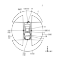
- FIG. 1 is a diagram illustrating an example of an overall configuration of an information processing system according to an embodiment.
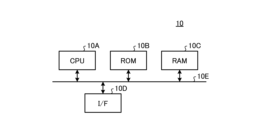
- FIG. 2 is a diagram illustrating an example of a hardware configuration of the information processing apparatus according to the embodiment.
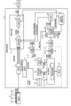
- FIG. 3 is a diagram illustrating an example of a functional configuration of the information processing device according to the embodiment.
- FIG. 4 is a schematic diagram illustrating an example of environment map information according to the embodiment.
- FIG. 5 is a schematic diagram illustrating an example of a functional configuration of the determination unit.
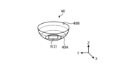
- FIG. 6 is a schematic diagram showing an example of the reference projection plane.
- FIG. 7 is an explanatory diagram of the asymptotic curve Q generated by the determination unit.
- FIG. 8 is a schematic diagram showing an example of a projection shape determined by the determination unit.
- FIG. 1 is a diagram illustrating an example of an overall configuration of an information processing system according to an embodiment.
- FIG. 2 is a diagram illustrating an example of a hardware configuration of the information processing apparatus according to the embodiment.
- FIG. 9 is a diagram for explaining the overhead image stabilization process.
- FIG. 10 is a diagram for explaining overhead image stabilization processing in a section in which the moving object is moving forward in the situation shown in FIG.
- FIG. 11 is a diagram for explaining overhead image stabilization processing in a section in which the moving object is moving forward in the situation shown in FIG.
- FIG. 12 is a diagram for explaining overhead image stabilization processing in a section in which the moving object is moving forward in the situation shown in FIG.
- FIG. 13 is a diagram for explaining the overhead image stabilization process when the moving object stops and the gear is changed from drive to reverse in the situation shown in FIG.
- FIG. 14 is a diagram for explaining the timing of switching from the generation process in the first mode to the generation process in the second mode in the overhead image stabilization process in the situation shown in FIG.
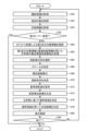
- FIG. 15 is a flowchart showing an example of the flow of overhead image stabilization processing according to the embodiment.
- FIG. 16 is a flowchart showing an example of the flow of the process of generating environment map information in the first mode until transition to the second mode.
- FIG. 17 is a flowchart showing an example of the flow of the overhead image generating process after transition from the first mode to the second mode.
- FIG. 18 is a diagram for explaining control of the frequency of the generation process of environment map information in the overhead image stabilization process according to the second embodiment.
- FIG. 19 is a diagram for explaining control of the frequency of the generation process of environment map information in the overhead image stabilization process according to the second embodiment.
- FIG. 16 is a flowchart showing an example of the flow of the process of generating environment map information in the first mode until transition to the second mode.
- FIG. 17 is a flowchart showing an example of the flow of the overhead image generating process after transition from the first mode to the second mode.
- FIG. 18 is a diagram for explaining control
- FIG. 20 is a diagram for explaining control of the frequency of the generation process of environment map information in the overhead image stabilization process according to the second embodiment.
- FIG. 21 is a diagram for explaining the timing of switching from the second mode generation process to the first mode generation process in the overhead image stabilization process in the situations shown in FIGS. 18, 19, and 20.
- FIG. 21 is a diagram for explaining the timing of switching from the second mode generation process to the first mode generation process in the overhead image stabilization process in the situations shown in FIGS. 18, 19, and 20.
- FIG. 1 is a diagram showing an example of the overall configuration of an information processing system 1 according to this embodiment.
- the information processing system 1 includes an information processing device 10, an image capturing unit 12, a detection unit 14, and a display unit 16.
- the information processing device 10, the image capturing unit 12, the detection unit 14, and the display unit 16 are connected to each other so as to be able to transmit and receive data or signals.
- the information processing device 10 the image capture unit 12, the detection unit 14, and the display unit 16 are described as being mounted on a moving object 2 as an example.
- the moving body 2 is an object that can move.
- the moving body 2 is, for example, a vehicle, a flyable object (a manned airplane, an unmanned airplane (e.g., a UAV (Unmanned Aerial Vehicle), a drone)), a robot, etc.
- the moving body 2 is, for example, a moving body that proceeds via a driving operation by a person, or a moving body that can proceed automatically (autonomous progression) without being driven by a person.
- a case where the moving body 2 is a vehicle is described as an example.
- Examples of vehicles include a two-wheeled vehicle, a three-wheeled vehicle, and a four-wheeled vehicle.
- a case where the vehicle is an autonomously progressing four-wheeled vehicle is described as an example.
- the information processing device 10 may be mounted on, for example, a stationary object.
- a stationary object is an object that is fixed to the ground.
- a stationary object is an object that cannot be moved or an object that is stationary relative to the ground. Examples of stationary objects include traffic lights, parked vehicles, and road signs.
- the information processing device 10 may also be mounted on a cloud server that executes processing on the cloud.
- the photographing unit 12 photographs the periphery of the moving object 2 and acquires photographed image data.
- the photographed image data will be simply referred to as a photographed image.
- the photographing unit 12 will be described assuming, for example, a digital camera capable of photographing video, such as a monocular fisheye camera with a viewing angle of approximately 195 degrees. Note that photographing refers to converting an image of a subject formed by an optical system such as a lens into an electrical signal.
- the photographing unit 12 outputs the photographed image to the information processing device 10.
- an example is described in which four imaging units 12, a front imaging unit 12A, a left imaging unit 12B, a right imaging unit 12C, and a rear imaging unit 12D, are mounted on the moving body 2.
- the multiple imaging units 12 (front imaging unit 12A, left imaging unit 12B, right imaging unit 12C, and rear imaging unit 12D) each capture a subject in a different direction in an imaging area E (front imaging area E1, left imaging area E2, right imaging area E3, and rear imaging area E4) to obtain a captured image.
- the imaging directions of the multiple imaging units 12 are different from each other.
- the imaging directions of the multiple imaging units 12 are adjusted in advance so that at least a portion of the imaging area E of the adjacent imaging units 12 overlaps.
- the imaging area E is shown in the size shown in FIG. 1 for convenience of explanation, but in reality it includes an area further away from the moving body 2.
- the four front imaging units 12A, left imaging unit 12B, right imaging unit 12C, and rear imaging unit 12D are merely examples, and there is no limit to the number of imaging units 12.
- the moving body 2 has a vertically long shape like a bus or truck, it is possible to place one imaging unit 12 at the front, rear, front of the right side, rear of the right side, front of the left side, and rear of the left side of the moving body 2, and use a total of six imaging units 12.
- the number and placement positions of the imaging units 12 can be set arbitrarily depending on the size and shape of the moving body 2.
- the detection unit 14 detects position information of each of a plurality of detection points around the moving body 2. In other words, the detection unit 14 detects position information of each of the detection points in the detection area F.
- a detection point refers to each of the points in real space that are individually observed by the detection unit 14.
- the detection points correspond to, for example, three-dimensional objects around the moving body 2.
- the detection unit 14 is an example of an external sensor.
- the detection unit 14 may be, for example, a 3D (three-dimensional) scanner, a 2D (two-dimensional) scanner, a distance sensor (millimeter wave radar, laser sensor), a sonar sensor that detects objects using sound waves, an ultrasonic sensor, etc.
- the laser sensor may be, for example, a three-dimensional LiDAR (laser imaging detection and ranging) sensor.
- the detection unit 14 may also be a device that uses a technology that measures distance from images captured by a stereo camera or a monocular camera, such as SfM (structure from motion) technology.
- Multiple image capture units 12 may also be used as the detection unit 14.
- One of the multiple image capture units 12 may also be used as the detection unit 14.
- the display unit 16 displays various information.
- the display unit 16 is, for example, an LCD (Liquid Crystal Display) or an organic EL (Electro-Luminescence) display.
- the information processing device 10 is communicatively connected to an electronic control unit (ECU: Electronic Control Unit) 3 mounted on the moving object 2.
- the ECU 3 is a unit that performs electronic control of the moving object 2.
- the information processing device 10 is capable of receiving CAN (Controller Area Network) data such as the speed and moving direction of the moving object 2 from the ECU 3.
- CAN Controller Area Network
- FIG. 2 is a diagram showing an example of the hardware configuration of the information processing device 10.
- the information processing device 10 includes a CPU (Central Processing Unit) 10A, a ROM (Read Only Memory) 10B, a RAM (Random Access Memory) 10C, and an I/F (InterFace) 10D, and is, for example, a computer.
- the CPU 10A, ROM 10B, RAM 10C, and I/F 10D are interconnected by a bus 10E, and have a hardware configuration that utilizes a normal computer.
- the CPU 10A is a calculation device that controls the information processing device 10.
- the CPU 10A corresponds to an example of a hardware processor.
- the ROM 10B stores programs and the like that realize various processes by the CPU 10A.
- the RAM 10C stores data necessary for various processes by the CPU 10A.
- the I/F 10D is an interface that connects to the imaging unit 12, the detection unit 14, the display unit 16, the ECU 3, etc., and transmits and receives data.
- the program (information processing program) for executing information processing executed by the information processing device 10 of this embodiment is provided by being pre-installed in ROM 10B or the like.
- the program executed by the information processing device 10 of this embodiment may be provided by being recorded on a recording medium in a format that can be installed on the information processing device 10 or in a format that can be executed.
- the recording medium is a medium that can be read by a computer.
- the recording medium is a CD (Compact Disc)-ROM, a flexible disk (FD), a CD-R (Recordable), a DVD (Digital Versatile Disk), a USB (Universal Serial Bus) memory, an SD (Secure Digital) card, etc.
- the information processing device 10 uses VSLAM processing to simultaneously estimate peripheral position information of the moving object 2 and self-position information of the moving object 2 from images captured by the image capture unit 12.
- the information processing device 10 stitches together multiple spatially adjacent captured images to generate and display a composite image (overhead image) overlooking the periphery of the moving object 2.
- at least one of the image capture units 12 is used as a detection unit 14, and the detection unit 14 processes the images acquired from the image capture unit 12.
- FIG. 3 is a diagram showing an example of the functional configuration of the information processing device 10. In addition to the information processing device 10, FIG. 3 also shows the image capture unit 12 and display unit 16 in order to clarify the data input/output relationship.
- the information processing device 10 includes an acquisition unit 20, a selection unit 21, an operation control unit 26, a VSLAM processing unit 24, a second memory unit 28, a determination unit 30, a transformation unit 32, a virtual viewpoint line of sight determination unit 34, and an image generation unit 37.
- Some or all of the above multiple units may be realized, for example, by having a processing device such as CPU 10A execute a program, i.e., by software. Also, some or all of the above multiple units may be realized by hardware such as an IC (Integrated Circuit), or by using a combination of software and hardware.
- the acquisition unit 20 acquires captured images from the image capture unit 12. That is, the acquisition unit 20 acquires captured images from each of the front image capture unit 12A, the left image capture unit 12B, the right image capture unit 12C, and the rear image capture unit 12D.
- the acquisition unit 20 outputs each captured image to the projection conversion unit 36 and the selection unit 21 each time the image is acquired.
- the selection unit 21 selects the detection area of the detection point. In this embodiment, the selection unit 21 selects the detection area by selecting at least one of the multiple imaging units 12 (imaging units 12A to 12D).
- the VSLAM processing unit 24 generates first information including position information of the surrounding three-dimensional objects of the moving body 2 and position information of the moving body 2 based on an image of the periphery of the moving body 2. That is, the VSLAM processing unit 24 receives the captured image from the selection unit 21, uses this to execute VSLAM processing to generate environmental map information, and outputs the generated environmental map information to the distance conversion unit 245.
- the VSLAM processing unit 24 also has a first mode generation process and a second mode generation process as operating modes for generating environmental map information.
- the first mode generation process is a mode in which map information including position information of objects around the moving body 2 is generated at a first frequency, and self-position information indicating the self-position of the moving body 2 is generated at a predetermined frequency.
- the second mode generation process is a mode in which map information is generated at a second frequency lower than the first frequency.
- frequency means the number of times the process is executed per unit time.
- the self-location information of the moving object 2 generated in the generation process of the first mode is called the first self-location information.
- This first self-location information is generated by VSLAM processing in the VSLAM processing unit 24.
- the self-location information of the moving object 2 generated in the self-location update unit 301 described below is called the second self-location information.
- This second self-location information is generated, for example, by odometry processing.
- the VSLAM processing unit 24 is an example of a map information generation unit.
- the VSLAM processing unit 24 includes a matching unit 240, a first memory unit 241, a self-position estimation unit 242, a three-dimensional restoration unit 243, and a correction unit 244.
- the matching unit 240 performs feature extraction processing and matching processing between multiple captured images (multiple captured images of different frames) captured at different times. In detail, the matching unit 240 performs feature extraction processing from these multiple captured images. The matching unit 240 performs matching processing for multiple captured images captured at different times, using the feature amounts between the multiple captured images to identify corresponding points between the multiple captured images. The matching unit 240 outputs the matching processing results to the first storage unit 241.
- the self-position estimation unit 242 uses the multiple matching points acquired by the matching unit 240 to estimate the self-position relative to the captured image as first self-position information by projective transformation or the like.
- the first self-position information includes information on the position (three-dimensional coordinates) and tilt (rotation) of the image capture unit 12.
- the self-position estimation unit 242 stores environmental map information 241A including the first self-position information as point cloud information in the first storage unit 241.
- the three-dimensional restoration unit 243 performs a perspective projection transformation process using the amount of movement (translation amount and rotation amount) of the first self-position information estimated by the self-position estimation unit 242, and determines the three-dimensional coordinates of the matching point (coordinates relative to the self-position).
- the three-dimensional restoration unit 243 stores the environment map information 241A, which includes the peripheral position information, which is the determined three-dimensional coordinates, as point cloud information, in the first storage unit 2431.
- new surrounding position information and new first self-position information are sequentially added to the environmental map information 241A as the moving object 2 on which the image capturing unit 12 is mounted moves.
- the first storage unit 241 stores various data such as environmental map information 241A.
- the first storage unit 241 is, for example, a semiconductor memory element such as a RAM or a flash memory, a hard disk, an optical disk, etc.
- the first storage unit 241 may be a storage device provided outside the information processing device 10.
- the first storage unit 241 may also be a storage medium.
- the storage medium may be a medium in which programs and various information are downloaded and stored or temporarily stored via a LAN (Local Area Network) or the Internet, etc.
- LAN Local Area Network
- the environmental map information 241A is information in which point cloud information, which is peripheral position information calculated by the three-dimensional restoration unit 243, and point cloud information, which is first self-position information calculated by the self-position estimation unit 242, are registered in a three-dimensional coordinate space with a predetermined position in real space as the origin (reference position).
- the predetermined position in real space may be determined based on, for example, preset conditions.
- the predetermined position used in the environmental map information 241A is the self-position of the moving body 2 when the information processing device 10 executes the information processing of this embodiment.
- the information processing device 10 may set the self-position of the moving body 2 when it is determined that the predetermined timing has been reached as the predetermined position.
- the information processing device 10 may determine that the predetermined timing has been reached when it is determined that the behavior of the moving body 2 has become behavior indicative of a parking scene.
- Behavior indicative of a parking scene due to reversing includes, for example, when the speed of the moving body 2 becomes equal to or lower than a predetermined speed, when the gear of the moving body 2 is put into reverse gear, when a signal indicating the start of parking is received by a user's operational instruction, etc. It should be noted that the predetermined timing is not limited to a parking scene.
- FIG. 4 is a schematic diagram of an example in which information on a specific height has been extracted from the environment map information 241A.
- the environment map information 241A is information in which point cloud information, which is the position information (peripheral position information) of each of the detection points P, and point cloud information, which is the self-position information of the self-position S of the moving object 2, are registered at corresponding coordinate positions in the three-dimensional coordinate space.
- FIG. 4 shows self-positions S1 to S3 as an example. The larger the value of the number following S, the closer the self-position S is to the current timing.
- the correction unit 244 corrects the surrounding position information and self-position information already registered in the environmental map information 241A using, for example, the least squares method, so that the sum of the difference in distance in three-dimensional space between previously calculated three-dimensional coordinates and newly calculated three-dimensional coordinates for points that have been matched multiple times between multiple frames is minimized. Note that the correction unit 244 may also correct the amount of movement (translation amount and rotation amount) of the self-position used in the process of calculating the self-position information and surrounding position information.
- the timing of the correction process by the correction unit 244 is not limited.
- the correction unit 244 may execute the above correction process at a predetermined timing.
- the predetermined timing may be determined based on a preset condition, for example. Note that in this embodiment, a case where the information processing device 10 is configured to include the correction unit 244 will be described as an example. However, the information processing device 10 may not be configured to include the correction unit 244.
- the distance conversion unit 245 converts the relative positional relationship between the self-position and the surrounding three-dimensional objects, which can be known from the environmental map information, into the absolute value of the distance from the self-position to the surrounding three-dimensional objects, generates detection point distance information of the surrounding three-dimensional objects, and outputs it to the determination unit 30.
- the detection point distance information is information obtained by offsetting the self-position to coordinates (0,0,0) and converting the measured distance (coordinates) to each of the multiple detection points P calculated, for example, into meters.
- the information on the self-position of the moving body 2 is included as the coordinates of the origin (0,0,0) in the detection point distance information.
- the distance conversion unit 245 uses, for example, status information such as the speed data of the moving object 2 included in the CAN data sent from the ECU 3 for distance conversion.
- status information such as the speed data of the moving object 2 included in the CAN data sent from the ECU 3 for distance conversion.
- the relative positional relationship between the self-position S and multiple detection points P can be known, but the absolute value of the distance is not calculated.
- the distance between the self-position S3 and the self-position S2 can be calculated based on the frame-to-frame period for calculating the self-position and the speed data during that period based on the status information.
- the distance conversion unit 245 uses the actual speed data of the moving object 2 included in the CAN data to convert the relative positional relationship between the self-position and the surrounding three-dimensional objects into the absolute value of the distance from the self-position to the surrounding three-dimensional objects.
- the status information included in the CAN data and the environmental map information output from the VSLAM processing unit 24 can be associated with each other using time information.
- the detection unit 14 acquires distance information of the detection point P, the distance conversion unit 245 may be omitted.
- the operation control unit 26 When the VSLAM processing unit 24 executes the generation process of the first mode, the operation control unit 26 generates first trigger information based on the status information of the moving object 2.
- the operation control unit 26 outputs the generated first trigger information to the VSLAM processing unit 24 and the self-position update unit 301 described later.
- the status information is information including at least one of the following: the speed data of the moving object 2 included in the CAN data sent from the ECU 3, gear information, the amount of rotation of the tires, the steering angle, an instruction from the user, and a trigger to start generating an overhead image.
- the first trigger information generated by the operation control unit 26 is information for transitioning the operation of the VSLAM processing unit 24 from the generation process of the first mode to the generation process of the second mode in order to reduce the frequency of generating environmental map information according to the status information of the moving object 2.
- the VSLAM processing unit 24 acquires the first trigger information from the operation control unit 26, it transitions the operation from the generation process of the first mode to the generation process of the second mode.
- the second storage unit 28 stores the environment map information including the self-position information of the moving object 2, which is sequentially output from the VSLAM processing unit 24 during the generation process of the first mode.
- the environment map information stored in the second storage unit 28 is referenced by the self-position update unit 301 of the determination unit 30 during the generation process of the second mode.
- the determination unit 30 determines the shape of the projection surface for projecting the image acquired by the image capture unit 12 mounted on the moving body 2 to generate an overhead image.
- the projection surface is a three-dimensional surface for projecting an image of the surroundings of the moving body 2 as an overhead image.
- the image of the surroundings of the moving body 2 is a captured image of the surroundings of the moving body 2, which is a captured image captured by each of the capturing units 12A to 12D.
- the projection shape of the projection surface is a three-dimensional (3D) shape that is virtually formed in a virtual space that corresponds to the real space.
- the determination of the projection shape of the projection surface executed by the determination unit 30 is referred to as a projection shape determination process.
- FIG. 5 is a schematic diagram showing an example of the functional configuration of the determination unit 30.
- the determination unit 30 includes a self-position update unit 301, a nearest neighbor identification unit 305, a reference projection surface shape selection unit 309, a scale determination unit 311, an asymptotic curve calculation unit 313, a shape determination unit 315, and a boundary region determination unit 317.
- the self-location update unit 301 reads out the environmental map information output from the VSLAM processing unit 24 and stored in the second storage unit 28, and outputs it to the nearest neighbor identification unit 305 in the subsequent stage.
- the self-location update unit 301 reads out the latest environmental map information stored in the second storage unit 28, and generates second self-location information by odometry processing using the first self-location information and state information contained in the latest environmental map information. The generation of this second self-location information is executed at a predetermined rate (frequency).
- the self-location update unit 301 registers the generated second self-location information in the retrieved environmental map information and outputs it to the nearest neighbor identification unit 305. Note that the self-location update unit 301 is an example of a self-location generation unit.
- the nearest neighbor identification unit 305 uses the specific height extraction map to divide the periphery of the self-position S of the moving body 2 into specific ranges (e.g., angular ranges), and for each range, identifies the detection point P closest to the moving body 2, or multiple detection points P in order of proximity to the moving body 2, and generates nearby point information.
- specific ranges e.g., angular ranges
- the nearest neighbor identification unit 305 identifies multiple detection points P for each range in order of proximity to the moving body 2 to generate nearby point information.
- the nearby point information is acquired as the positions of nearby points, for example, every 90 degrees, in four directions, forward, left, right, and backward of the moving body 2.
- the nearest neighbor identification unit 305 outputs the measurement distance of the detection point P identified for each range as nearby point information to the downstream reference projection surface shape selection unit 309, scale determination unit 311, asymptotic curve calculation unit 313, and boundary region determination unit 317.
- the reference projection surface shape selection unit 309 selects the shape of the reference projection surface.
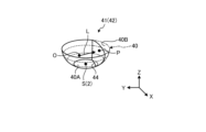
- FIG. 6 is a schematic diagram showing an example of a reference projection surface 40.
- the reference projection surface will be described with reference to FIG. 6.
- the reference projection surface 40 is, for example, a projection surface having a shape that serves as a reference when changing the shape of the projection surface.
- the shape of the reference projection surface 40 is, for example, bowl-shaped, cylindrical, etc. Note that FIG. 6 shows an example of a bowl-shaped reference projection surface 40.
- the bowl shape has a bottom surface 40A and a side wall surface 40B, one end of the side wall surface 40B is continuous with the bottom surface 40A, and the other end is open.
- the width of the horizontal cross section of the side wall surface 40B increases from the bottom surface 40A side toward the opening of the other end.
- the bottom surface 40A is, for example, circular.
- a circular shape includes a perfect circle shape and a circular shape other than a perfect circle shape, such as an ellipse shape.
- the horizontal cross section is an orthogonal plane perpendicular to the vertical direction (arrow Z direction).
- the orthogonal plane is a two-dimensional plane along the arrow X direction perpendicular to the arrow Z direction, and the arrow Y direction perpendicular to the arrow Z direction and the arrow X direction.
- the horizontal cross section and the orthogonal plane may be referred to as the XY plane below.
- the bottom surface 40A may be a shape other than a circle, such as an egg shape.
- the cylindrical shape is a shape consisting of a circular bottom surface 40A and a side wall surface 40B that is continuous with the bottom surface 40A.
- the side wall surface 40B that constitutes the cylindrical reference projection surface 40 is cylindrical with an opening at one end that is continuous with the bottom surface 40A and an opening at the other end.
- the side wall surface 40B that constitutes the cylindrical reference projection surface 40 has a shape in which the diameter in the XY plane is approximately constant from the bottom surface 40A side toward the opening side of the other end.
- the bottom surface 40A may be a shape other than a circle, such as an egg shape.
- the reference projection plane 40 is a three-dimensional model virtually formed in a virtual space with the bottom surface 40A being a surface that approximately coincides with the road surface below the moving body 2, and the center of the bottom surface 40A being the self-position S of the moving body 2.
- the reference projection surface shape selection unit 309 selects the shape of the reference projection surface 40 by reading one specific shape from multiple types of reference projection surfaces 40. For example, the reference projection surface shape selection unit 309 selects the shape of the reference projection surface 40 based on the positional relationship and distance between the self-position and surrounding three-dimensional objects. The shape of the reference projection surface 40 may also be selected based on an operational instruction from the user. The reference projection surface shape selection unit 309 outputs shape information of the determined reference projection surface 40 to the shape determination unit 315. In this embodiment, as described above, a form in which the reference projection surface shape selection unit 309 selects a bowl-shaped reference projection surface 40 is described as an example.
- the scale determination unit 311 determines the scale of the reference projection surface 40 of the shape selected by the reference projection surface shape selection unit 309. For example, the scale determination unit 311 makes a decision to reduce the scale when the distance from the self-position S to a nearby point is shorter than a predetermined distance.
- the scale determination unit 311 outputs scale information of the determined scale to the shape determination unit 315.
- the asymptotic curve calculation unit 313 calculates the asymptotic curve of the peripheral position information relative to the self-position based on the peripheral position information of the moving object 2 and the self-position information contained in the environmental map information.
- the asymptotic curve calculation unit 313 uses each of the distances from the self-position S to the closest detection point P for each range from the self-position S received from the nearest neighbor identification unit 305, and outputs the asymptotic curve information of the calculated asymptotic curve Q to the shape determination unit 315 and the virtual viewpoint line of sight determination unit 34.
- FIG. 7 is an explanatory diagram of the asymptotic curve Q generated by the determination unit 30.
- the asymptotic curve is the asymptotic curve of multiple detection points P in the environmental map information.
- FIG. 7 is an example showing the asymptotic curve Q in a projected image obtained by projecting a captured image onto a projection surface when the moving body 2 is viewed from above.
- the determination unit 30 has identified three detection points P in order of proximity to the self-position S of the moving body 2.
- the determination unit 30 generates the asymptotic curve Q of these three detection points P.
- the asymptotic curve calculation unit 313 may obtain a representative point located at the center of gravity of multiple detection points P for each specific range (e.g., angle range) of the reference projection plane 40, and calculate an asymptotic curve Q for the representative point for each of the multiple ranges. Then, the asymptotic curve calculation unit 313 outputs asymptotic curve information of the calculated asymptotic curve Q to the shape determination unit 315. The asymptotic curve calculation unit 313 may output asymptotic curve information of the calculated asymptotic curve Q to the virtual viewpoint line of sight determination unit 34.
- the shape determination unit 315 enlarges or reduces the reference projection surface 40, the shape of which is indicated by the shape information received from the reference projection surface shape selection unit 309, to the scale of the scale information received from the scale determination unit 311.
- the shape determination unit 315 determines, as the projection shape, the shape of the reference projection surface 40 after enlargement or reduction, which is deformed so that the shape conforms to the asymptotic curve information of the asymptotic curve Q received from the asymptotic curve calculation unit 313.
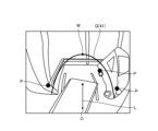
- FIG. 8 is a schematic diagram showing an example of the projection shape 41 determined by the determination unit 30.
- the shape determination unit 315 determines, as the projection shape 41, a shape obtained by deforming the reference projection plane 40 into a shape that passes through a detection point P that is closest to the self-position S of the moving object 2, which is the center of the bottom surface 40A of the reference projection plane 40.
- a shape that passes through the detection point P means that the deformed side wall surface 40B is a shape that passes through the detection point P.
- the self-position S is the self-position S calculated by the self-position estimation unit 242.
- the shape determination unit 315 identifies the detection point P that is closest to the self-position S among the multiple detection points P registered in the environmental map information.
- the shape determination unit 315 identifies the detection point P where the value of X2 + Y2 is the minimum as the detection point P that is closest to the self-position S.
- the shape determination unit 315 determines, as the projection shape 41, a shape obtained by deforming the side wall surface 40B of the reference projection plane 40 so that it passes through the detection point P.
- the shape determination unit 315 determines the deformed shape of the bottom surface 40A and a portion of the side wall surface 40B as the projected shape 41 so that when the reference projection surface 40 is deformed, a portion of the side wall surface 40B becomes a wall surface passing through the detection point P closest to the moving body 2.
- the projected shape 41 after deformation is, for example, a shape raised from the rising line 44 on the bottom surface 40A toward the center of the bottom surface 40A from the viewpoint (planar view) of the XY plane. "Raising” means, for example, bending or folding a portion of the side wall surface 40B and the bottom surface 40A toward the center of the bottom surface 40A so that the angle between the side wall surface 40B of the reference projection surface 40 and the bottom surface 40A becomes smaller. Note that in the raised shape, the rising line 44 may be located between the bottom surface 40A and the side wall surface 40B, and the bottom surface 40A may remain undeformed.
- the shape determination unit 315 determines to deform the specific area on the reference projection surface 40 so that it protrudes to a position that passes through the detection point P when viewed from the viewpoint (planar view) of the XY plane.
- the shape and range of the specific area may be determined based on predetermined criteria.
- the shape determination unit 315 determines to deform the reference projection surface 40 so that the distance from the self-position S increases continuously from the protruding specific area toward areas on the side wall surface 40B other than the specific area.
- the shape determination unit 315 is an example of a projection shape determination unit.
- the projection shape 41 it is preferable to determine the projection shape 41 so that the outer periphery of the cross section along the XY plane is curved.
- the outer periphery of the cross section of the projection shape 41 is, for example, circular, but may be a shape other than circular.
- the shape determination unit 315 may determine, as the projection shape 41, a shape obtained by deforming the reference projection plane 40 so that the shape is along an asymptotic curve.
- the shape determination unit 315 generates an asymptotic curve of a predetermined number of detection points P in a direction away from the detection point P closest to the self-position S of the moving body 2.
- the number of detection points P may be more than one.
- the number of detection points P is preferably three or more.
- the shape determination unit 315 generates an asymptotic curve of a plurality of detection points P located at a position away from the self-position S by a predetermined angle or more.
- the shape determination unit 315 may determine, as the projection shape 41, a shape obtained by deforming the reference projection plane 40 so that the shape is along the generated asymptotic curve Q in the asymptotic curve Q shown in FIG. 7.
- the shape determination unit 315 may divide the periphery of the self-position S of the moving body 2 into specific ranges, and for each range, identify the detection point P closest to the moving body 2, or multiple detection points P in order of proximity to the moving body 2. The shape determination unit 315 may then determine, as the projection shape 41, a shape obtained by deforming the reference projection surface 40 so that the shape passes through the detection points P identified for each range, or a shape that follows the asymptotic curve Q of the identified multiple detection points P.
- the shape determination unit 315 outputs the projection shape information of the determined projection shape 41 to the deformation unit 32.
- the deformation unit 32 deforms the projection plane based on the projection shape information received from the determination unit 30.
- the deformation of this reference projection plane is performed, for example, based on the detection point P closest to the moving body 2.
- the deformation unit 32 outputs the deformed projection plane information to the projection conversion unit 36.
- the deformation unit 32 deforms the reference projection surface into a shape that follows the asymptotic curve of a predetermined number of detection points P in order of proximity to the moving body 2, based on the projection shape information.
- the virtual viewpoint line of sight determination unit 34 determines virtual viewpoint line of sight information based on the self-position and the asymptotic curve information, and outputs it to the projection transformation unit 36.
- the virtual viewpoint line of sight determination unit 34 determines the line of sight direction to be a direction passing through the detection point P closest to the self-position S of the moving body 2 and perpendicular to the deformed projection plane. Also, for example, the virtual viewpoint line of sight determination unit 34 fixes the direction of the line of sight direction L, and determines the coordinates of the virtual viewpoint O as an arbitrary Z coordinate and an arbitrary XY coordinate in a direction away from the asymptotic curve Q toward the self-position S. In this case, the XY coordinates may be coordinates of a position farther away from the asymptotic curve Q than the self-position S.
- the virtual viewpoint line of sight determination unit 34 outputs the virtual viewpoint line of sight information indicating the virtual viewpoint O and the line of sight direction L to the projection transformation unit 36.
- the line of sight direction L may be a direction from the virtual viewpoint O toward the position of the apex W of the asymptotic curve Q.
- the image generation unit 37 uses the projection surface to generate an overhead image of the surroundings of the moving object 2. Specifically, the image generation unit 37 includes a projection conversion unit 36 and an image synthesis unit 38.
- the projection conversion unit 36 generates a projection image by projecting the captured image acquired from the image capture unit 12 onto the deformed projection surface based on the deformed projection surface information and the virtual viewpoint line of sight information.
- the projection conversion unit 36 converts the generated projection image into a virtual viewpoint image and outputs it to the image synthesis unit 38.
- the virtual viewpoint image is an image obtained by viewing the projection image in any direction from the virtual viewpoint.
- the projection image generation process by the projection transformation unit 36 will be described in detail with reference to FIG. 8.
- the projection transformation unit 36 projects the captured image onto the deformed projection surface 42.
- the projection transformation unit 36 then generates a virtual viewpoint image (not shown) which is an image of the captured image projected onto the deformed projection surface 42 viewed from an arbitrary virtual viewpoint O in the line of sight direction L.
- the position of the virtual viewpoint O may be set to, for example, the self-position S of the moving body 2 (used as the basis for the projection surface deformation process).
- the XY coordinate values of the virtual viewpoint O may be set to the XY coordinate values of the self-position of the moving body 2.
- the Z coordinate value (vertical position) of the virtual viewpoint O may be set to the Z coordinate value of the detection point P closest to the self-position of the moving body 2.
- the line of sight direction L may be determined based on, for example, a predetermined criterion.
- the line of sight direction L may be, for example, a direction from the virtual viewpoint O toward the detection point P that is closest to the self-position S of the moving body 2.
- the line of sight direction L may also be a direction that passes through the detection point P and is perpendicular to the deformed projection plane 42.
- the virtual viewpoint line of sight information indicating the virtual viewpoint O and the line of sight direction L is created by the virtual viewpoint line of sight determination unit 34.
- the image synthesis unit 38 generates a synthetic image by extracting part or all of the virtual viewpoint image. For example, the image synthesis unit 38 performs a process of stitching together multiple virtual viewpoint images (here, four virtual viewpoint images corresponding to the imaging units 12A to 12D) in the boundary area between the imaging units.
- multiple virtual viewpoint images here, four virtual viewpoint images corresponding to the imaging units 12A to 12D
- the image synthesis unit 38 outputs the generated synthetic image to the display unit 16.
- the synthetic image may be a bird's-eye view image with a virtual viewpoint O above the moving body 2, or may be an image in which the moving body 2 is displayed semi-transparently with a virtual viewpoint O inside the moving body 2.
- the overhead image stabilization process executed by the information processing device 10 according to the present embodiment will be described in detail.
- a high load such as overhead image display accompanied by deformation of the projection surface
- environmental map information generation which also has a high processing load
- the overhead image may become unstable, such as the displayed overhead image becoming unnatural.
- the overhead image stabilization process is a process for reducing the load of information processing by controlling the frequency of environmental map information generation according to the vehicle state of the moving body 2, and stabilizing the overhead image generation.
- an example is taken in which the acquisition of status information in which the gear of the moving body 2 has been changed from drive to reverse is used as a trigger to start the overhead image stabilization process.
- this is not limited to this example, and the start of the overhead image stabilization process may also be triggered by, for example, the acquisition of status information including instruction information for the overhead image stabilization process input by the user and overhead image generation start information.
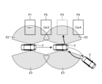
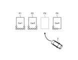
- FIG. 9 is a top view illustrating the overhead image stabilization process, showing an example of the movement path of the mobile body 2 and the surrounding conditions of the parking area P3 when the mobile body 2 is parked in the parking area P3.
- Car1 is in parking area P1
- Car2 is in parking area P2
- Car4 is in parking area P4.
- parking area P3, which is between parking area P2 and parking area P4, is vacant.
- the mobile body 2 proceeds from parking area P1 while looking at parking area P4 on the left, stops with the front of the vehicle facing to the right beyond parking area P4, and then shifts the gear from drive to reverse to reverse and parks in parking area P3.
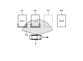
- FIG. 10, 11, and 12 are diagrams for explaining the overhead image stabilization process in the section where the moving body 2 is moving forward in the situation shown in FIG. 9.
- the moving body 2 proceeds from parking area P1 while looking at parking area P4 on the left, and until it stops beyond parking area P4 with the front of the vehicle facing right, the VSLAM processing unit 24 performs environment map information generation and self-position estimation using images captured in the left shooting area E2 by the generation process in the first mode. Therefore, in the section shown in FIG. 10, 11, and 12, environment map information including self-maintenance information is generated with the first frequency.
- the circles shown on the boundaries of Car in Figures 10, 11, and 12 indicate detection points detected in VSLAM processing.
- the diagonal-lined circles are examples of detection points detected in the current VSLAM processing
- the open circles are examples of detection points detected in past VSLAM processing.
- FIG. 13 is a diagram for explaining the overhead image stabilization process when the moving object 2 stops and changes gear from drive to reverse in the situation shown in FIG. 9.
- the operation control unit 26 obtains state information related to the gear change of the moving object 2 from the ECU 3, generates first trigger information based on the state information, and outputs it to the VSLAM processing unit 24 and the self-position update unit 301.
- the VSLAM processing unit 24 transitions the environment map information generation process from a first mode in which the process is executed at a first frequency to a second mode in which the process is executed at a second frequency lower than the first frequency. Thereafter, the VSLAM processing unit 24 executes the environment map information generation process according to the second mode.
- the second frequency can be set to any value lower than the first frequency.
- the setting value of the second frequency is set to "0", and an example is taken in which no new environment map information is generated in the generation process in the second mode.
- the setting value is a numerical value that determines the number of times the process is executed per unit time, and for example, when "0" is set, this means that the environment map information is generated 0 times per unit time, i.e., no environment map information is generated.
- the self-position updating unit 301 In response to the first trigger information acquired from the operation control unit 26, the self-position updating unit 301 reads, for example, the latest environmental map information (including the first self-position information) from the second storage unit 28.
- the self-position updating unit 301 also starts a self-position estimation process using the odometry method, using the status information acquired from the ECU 3 and the read environmental map information.
- the self-position updating unit 301 registers the second self-position information generated by the self-position estimation process in the environmental map information.
- the self-position updating unit 301 outputs the environmental map information in which the second self-position information is registered to the nearest neighbor identification unit 305 at the subsequent stage.
- the determination unit 30 executes a projection shape determination process using the environment map information generated in the first mode and stored in the second storage unit 28 and the second self-position information updated in real time.
- the image generation unit 37 generates an overhead image using the projection surface shape determined by the environment map information generated in the first mode and stored in the second storage unit 28 and the second self-position information updated in real time.
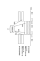
- FIG. 14 is a diagram for explaining the timing of switching from the first mode generation process to the second mode generation process in the overhead image stabilization process in the situation shown in FIG. 9 (i.e., switching between generating environmental map information and generating self-location information).
- the generation process of the first mode while the moving body 2 is moving forward, the generation process of the first mode generates the environment map information and the first self-position information at a first frequency.
- the generated environment map information and the first self-position information are stored sequentially in the second storage unit 28.
- the generation process of the first mode transitions to the generation process of the second mode.
- the moving body 2 moves toward the environment map information already generated by the generation process of the first mode due to reverse parking. Therefore, in the generation process of the second mode, the environment map information is not generated, and an overhead image is generated using the environment map information already generated by the generation process of the first mode and the second self-position information generated by the odometry method.
- the generation of the environmental map generation information can be stopped, which reduces the processing load.
- a natural overhead image can be stably generated and output.
- FIG. 15 is a flowchart showing an example of the flow of overhead image stabilization processing according to an embodiment. Note that the overhead image stabilization processing shown in FIG. 15 shows an example of overhead image stabilization processing executed in the situation shown in FIG. 9.
- the VSLAM processing unit 24 generates environmental map information by the generation process in the first mode in the section in which the moving body 2 advances (step S1).
- the VSLAM processing unit 24 generates first self-location information in the generation process of the first mode (step S2).
- the generated first self-location information is registered in the environmental map information generated in step S1.
- the VSLAM processing unit 24 outputs the environmental map information in which the first self-location information is registered to the second storage unit 28.
- the second storage unit 28 stores (updates) the environmental map information output from the VSLAM processing unit 24 (step S3). Note that the generation of the environmental map information by steps S1 to S3 is performed with a first frequency.
- the VSLAM processing unit 24 determines whether or not the first trigger information has been acquired from the operation control unit 26 (step S4). If the VSLAM processing unit 24 has not acquired the first trigger information from the operation control unit 26 (No in step S4), it repeats the processing of steps S1 to S3.
- the VSLAM processing unit 24 receives first trigger information from the operation control unit 26 (Yes in step S4), it stops generating environmental map information in the first mode and transitions the operation from the generation process in the first mode to the generation process in the second mode (step S5).
- the self-location update unit 301 acquires the latest environmental map information and the first self-location information from the second storage unit 28 (step S6).
- the self-location update unit 301 acquires the status information (step S7).
- the self-location update unit 301 executes odometry processing using the acquired environmental map information and state information to generate second self-location information (step S8).
- step S9 If the self-location update unit 301 has not received the second trigger information from the operation control unit 26 (No in step S9), it repeats the processes of steps S7 and S8. On the other hand, if the self-location update unit 301 has received the second trigger information from the operation control unit 26 (Yes in step S9), it stops the generation of environmental map information by the second mode generation process (step S9).
- the setting value of the second frequency is set to 0.
- the processes of steps S1, S2, S3, S5, and S6 are executed as periodic interrupt processes according to the second frequency.
- FIG. 16 is a flowchart showing an example of the flow of the process of generating environmental map information in the first mode until transition to the second mode.
- the acquisition unit 20 acquires the captured images for each direction (step S20).
- the operation control unit 26 acquires the specified content (step S22). The operation control unit 26 also acquires the status information (step S24).
- the operation control unit 26 determines whether or not to transition the operation of the VSLAM processing unit 24 from the first mode to the second mode based on the acquired state information (step S26).
- step S26 If the operation control unit 26 determines to transition from the first mode to the second mode (Yes in step S26), the operation control unit 26 generates first trigger information and outputs it to the VSLAM processing unit 24 and the self-position update unit 301.
- the decision unit 30 of the VSLAM processing unit 24 ends (stops) the generation process of the first mode in response to the first trigger information acquired from the operation control unit 26. Thereafter, the overhead image generation process (described later) after transition to the second mode shown in FIG. 17 is executed.
- the operation control unit 26 determines not to transition from the first mode to the second mode (No in step S26)
- the operation control unit 26 does not generate the first trigger information.
- the VSLAM processing unit 24 does not receive the first trigger information from the operation control unit 26, and the selection unit 21 of the VSLAM processing unit 24 selects the captured image as the detection area (step S28).
- the matching unit 240 extracts features and performs matching processing using the multiple captured images taken at different times and selected in step S28 and captured by the imaging unit 12 (step S30).
- the matching unit 240 also registers information on corresponding points between the multiple captured images taken at different times, identified by the matching processing, in the first storage unit 241.
- the self-position estimation unit 242 reads the matching points and the environmental map information 241A (peripheral position information and self-position information) from the first storage unit 241 (step S32). Using the multiple matching points acquired from the matching unit 240, the self-position estimation unit 242 estimates the self-position relative to the captured image by projective transformation or the like (step S34), and registers the calculated self-position information in the environmental map information 241A (step S36).
- the three-dimensional restoration unit 243 reads the environment map information 241A (peripheral position information and self-position information) (step S38).
- the three-dimensional restoration unit 243 performs a perspective projection transformation process using the amount of movement (translation amount and rotation amount) of the self-position estimated by the self-position estimation unit 242, determines the three-dimensional coordinates of the matching point (coordinates relative to the self-position), and registers them as peripheral position information in the environment map information 241A (step S40).
- the correction unit 244 reads the environment map information 241A (peripheral position information and self-position information) (step S42).
- the correction unit 244 corrects the peripheral position information and self-position information already registered in the environment map information 241A using, for example, the least squares method so that the sum of the distance differences in three-dimensional space between previously calculated three-dimensional coordinates and newly calculated three-dimensional coordinates for points that have been matched multiple times across multiple frames is minimized (step S44), and updates the environment map information 241A.
- the distance conversion unit 245 acquires status information, including the speed data (vehicle speed) of the moving body 2, contained in the CAN data received from the ECU 3 of the moving body 2 (step S46).
- the distance conversion unit 245 uses the speed data of the moving body 2 to convert the coordinate distance between the point groups contained in the environmental map information 241A into an absolute distance, for example in meters.
- the distance conversion unit 245 also offsets the origin of the environmental map information to the self-position S of the moving body 2 to generate detection point distance information indicating the distance from the moving body 2 to each of the multiple detection points P (step S48).
- the distance conversion unit 245 outputs the detection point distance information to the second storage unit 28 as first self-position information.
- the second storage unit 28 stores (updates) the environmental map information including the first self-position information output from the distance conversion unit 245 (step S50).
- FIG. 17 is a flowchart showing an example of the flow of the overhead image generation process after transitioning from the first mode to the second mode. Note that the processes from step S20 to step S26 are the same as those shown in FIG. 16, so the description thereof will be omitted.
- the self-location update unit 301 After the operation of the VSLAM processing unit 24 transitions to the generation process of the second mode, the self-location update unit 301 generates second self-location information by odometry processing (step S60). The self-location update unit 301 also outputs the environmental map information in which the generated second self-location information is registered to the nearest neighbor identification unit 305.
- the nearest neighbor identification unit 305 executes nearest object distance extraction processing for each direction using the environment map information including the first self-location information and the second self-location information (step S62). Specifically, the nearest neighbor identification unit 305 divides the surroundings of the self-location S of the moving body 2 into specific ranges, identifies the detection point P closest to the moving body 2 for each range, or multiple detection points P in order of closestness to the moving body 2, and extracts the distance to the nearest object. The nearest neighbor identification unit 305 outputs the measured distance d of the detection point P identified for each range (the measured distance between the moving body 2 and the nearest object) to the subsequent stage as nearby point information.
- the reference projection surface shape selection unit 309 selects the shape of the reference projection surface 40 based on the nearby point information (step S64), and outputs the shape information of the selected reference projection surface 40 to the shape determination unit 315.
- the scale determination unit 311 determines the scale of the reference projection surface 40 of the shape selected by the reference projection surface shape selection unit 309 (step S66), and outputs the scale information of the determined scale to the shape determination unit 315.
- the asymptotic curve calculation unit 313 calculates an asymptotic curve based on the neighboring point information input from the nearest neighbor identification unit 305 (step S68), and outputs the asymptotic curve information to the shape determination unit 315 and the virtual viewpoint line of sight determination unit 34.
- the shape determination unit 315 determines the projection shape, based on the scale information and the asymptotic curve information, how to deform the shape of the reference projection surface (step S70).
- the shape determination unit 315 outputs the projection shape information of the determined projection shape 41 to the deformation unit 32.
- the deformation unit 32 deforms the shape of the reference projection surface based on the projection shape information (step S72).
- the deformation unit 32 outputs the deformed projection surface information to the projection conversion unit 36.
- the virtual viewpoint line of sight determination unit 34 determines virtual viewpoint line of sight information based on the self-position and the asymptotic curve information (step S74).
- the virtual viewpoint line of sight determination unit 34 outputs the virtual viewpoint line of sight information indicating the virtual viewpoint O and the line of sight direction L to the projection transformation unit 36.
- the projection conversion unit 36 generates a projection image by projecting the captured image acquired from the image capture unit 12 onto the deformed projection surface based on the deformed projection surface information and the virtual viewpoint line of sight information.
- the projection conversion unit 36 converts (generates) the generated projection image into a virtual viewpoint image (step S76) and outputs it to the image synthesis unit 38.
- the boundary area determination unit 317 determines the boundary area based on the distance to the nearest object identified for each range. In other words, the boundary area determination unit 317 determines the boundary area as an overlapping area of spatially adjacent peripheral images based on the position of the object nearest to the moving body 2. The boundary area determination unit 317 outputs the determined boundary area to the image synthesis unit 38.
- the image synthesis unit 38 joins spatially adjacent virtual viewpoint images together using the boundary region to generate a synthetic image (step S78). Note that in the boundary region, spatially adjacent virtual viewpoint images can also be blended at a predetermined ratio.
- the display unit 16 displays the composite image as an overhead image (step S80).
- the information processing device 10 determines whether or not to end the information processing (step S82). For example, the information processing device 10 makes the determination in step S82 by determining whether or not a signal indicating that parking of the mobile object 2 has been completed has been received from the ECU 3. Also, for example, the information processing device 10 may make the determination in step S82 by determining whether or not an instruction to end the information processing has been received through an operational instruction by the user, etc.
- step S82 If a negative judgment is made in step S82 (No in step S82), the processes from step S20 to step S80 are repeatedly executed. On the other hand, if a positive judgment is made in step S82 (Yes in step S82), the overhead image generation process including the projection shape optimization process according to the embodiment is terminated.
- the information processing device 10 includes a VSLAM processing unit 24 as a map information generating unit, and a self-location updating unit 301 as a self-location generating unit.
- the VSLAM processing unit 24 selectively executes a first mode generation process in which map information including position information of objects around the moving body 2 is generated at a first frequency to generate first self-location information indicating the self-location of the moving body 2, and a second mode generation process in which map information is generated at a second frequency lower than the first frequency.
- the VSLAM processing unit 24 executes the first mode generation process while the moving body 2 is moving forward, and executes the second mode generation process while the moving body 2 is moving backward.
- the self-location updating unit 301 uses the first self-location information and state information of the moving body 2 to generate second self-location information, which is the position information of the moving body 2 in the map information.
- the VSLAM processing unit 24 executes the generation process in the first mode, for example, when the moving body 2 is moving forward, and executes the generation process in the second mode when the moving body 2 is moving backward, thereby relatively reducing the frequency of the map information generation process, which has a high processing load while moving backward and generates and displays an overhead image. As a result, a stable overhead image can be generated and displayed while moving backward.
- the VSLAM processing unit 24 of the information processing device 10 can set the second frequency to zero in the generation process in the second mode to stop the generation of map information. Therefore, the information processing device 10 can significantly reduce the processing load during reversing when generating and displaying an overhead image.
- the information processing device 10 further includes an operation control unit 26 that generates first trigger information based on the status information of the moving object 2.
- the VSLAM processing unit 24 transitions the operation from the first mode generation process to the second mode generation process in response to the first trigger information.
- the self-location update unit 301 starts generating second self-location information in response to the first trigger information.
- the status information of the moving object 2 can be at least one of the gear change information of the moving object 2, instruction information input by the user, and overhead image generation start information. Therefore, the information processing device 10 can relatively reduce the frequency of map information generation processing, which has a high processing load, at an appropriate timing according to the vehicle status of the moving object 2.
- the self-location update unit 301 of the information processing device 10 generates second self-location information using an odometry method using the state information of the moving body, starting from the first self-location information.
- the self-location update unit 301 calculates distance information to objects in the vicinity of the moving body 2 using the second self-location information and environmental map information. Therefore, the information processing device 10 can acquire self-location information using the odometry method, which has a relatively light processing load, without performing VSLAM processing, and can significantly reduce the processing load.
- the information processing device 10 further includes an image generation unit 37 as an image synthesis unit that starts generating an overhead image of the periphery of the moving object in response to the first trigger information.
- the image generation unit 37 deforms the projection surface of the overhead image based on the distance information. Therefore, since the overhead image generation starts after transitioning to the generation process of the second mode, the processing load can be significantly reduced without simultaneously generating the overhead image and performing VSLAM processing.
- the moving body 2 may stop moving backward, change gear from reverse to drive, and move forward again, for example, when the direction of the moving body 2 is not appropriate or when the planned parking position is changed.
- the overhead image stabilization process in such a case will be described.
- FIGS. 18, 19, and 20 are diagrams for explaining the control of the frequency of the generation process of environmental map information in the overhead image stabilization process according to the second embodiment.
- the moving body 2 proceeds from parking area P1 towards parking area P4, and once it approaches parking area P4, it stops with the front of the vehicle facing to the right.
- the moving body 2 then changes gear from drive to reverse, and moves backward towards parking area P3 as shown in FIG. 19.
- the moving body 2 stops moving backward, changes gear from reverse to drive, and moves forward again as shown in FIG. 20.
- the first mode generation process is executed, and when the moving body 2 changes gear from drive to reverse, the operation control unit 26 outputs first trigger information, and the operation of the VSLAM processing unit 24 transitions from the first mode generation process to the second mode generation process. Therefore, during reverse movement of the moving body 2 as shown in FIG. 19, overhead image generation according to overhead image stabilization process is executed.
- the operation control unit 26 Furthermore, at the timing when the moving object 2 stops reversing and changes gear from reverse to drive, the operation control unit 26 generates second trigger information based on the status information of the moving object 2.
- the operation control unit 26 outputs the generated second trigger information to the VSLAM processing unit 24 and the self-position update unit 301.
- the second trigger information generated by the operation control unit 26 is information for transitioning the operation of the VSLAM processing unit 24 from second mode generation processing to first mode generation processing in order to increase the frequency of environmental map information generation according to the status information of the moving object 2.
- VSLAM processing unit 24 acquires the second trigger information from the operation control unit 26, it transitions the operation from the second mode generation process to the first mode generation process. Also, when the self-location update unit 301 acquires the second trigger information from the operation control unit 26, it stops generating the second self-location information by the odometry process.
- FIG. 21 is a diagram for explaining the timing of switching from the second mode generation process to the first mode generation process in the overhead image stabilization process in the situations shown in FIGS. 18, 19, and 20.
- the environment map information and first self-position information are generated at a first frequency by the first mode generation process.
- the generation process transitions from the first mode generation process to the second mode generation process.
- the generation process transitions from the second mode generation process to the first mode generation process.
- new environment map information and first self-position information are generated by VSLAM processing at the first frequency.
- the VSLAM processing unit 24 may obtain the second self-location information estimated by the odometry processing of the self-location update unit 301 and treat it as the latest self-location when the generation processing of the first mode is resumed. It may also match the stored second self-location information with the first self-location information estimated when the generation processing of the first mode is newly performed.
- the information processing device 10 of the above embodiment and each modified example can be applied to various devices.
- the information processing device 10 of the above embodiment and each modified example can be applied to a surveillance camera system that processes images obtained from a surveillance camera, or an in-vehicle system that processes images of the surrounding environment outside the vehicle.
Landscapes
- Engineering & Computer Science (AREA)
- Physics & Mathematics (AREA)
- General Physics & Mathematics (AREA)
- Theoretical Computer Science (AREA)
- Geometry (AREA)
- Software Systems (AREA)
- Computer Vision & Pattern Recognition (AREA)
- Computer Graphics (AREA)
- Remote Sensing (AREA)
- Image Processing (AREA)
- Image Analysis (AREA)
Abstract
Description
以下、図3に示した決定部30の詳細な構成の一例を説明する。
次に、本実施形態に係る情報処理装置10が実行する俯瞰画像安定化処理について詳しく説明する。例えば投影面変形を伴う俯瞰画像表示等の負荷が大きい情報処理を実行する場合に、同じく処理負荷が大きい環境地図情報生成を通常の頻度で継続して実行した場合、表示される俯瞰画像が不自然になるなど、俯瞰画像が不安定になる可能性がある。俯瞰画像安定化処理とは、移動体2の車両状態に応じて環境地図情報生成の頻度を制御して情報処理の負荷を軽減し、俯瞰画像生成を安定化させるものである。
移動体2が駐車領域に駐車しようとして後退した後、例えば、移動体2の向きが適切でなかった場合や駐車予定位置を変更する等の理由により、後退を停止してリバースからドライブにギアチェンジし再度前進することがある。第2実施形態は、係る場合における俯瞰画像安定化処理について説明する。
上記各実施形態では、移動体2の状態情報に応じて、環境地図情報の生成頻度の異なる二種類のモード(第1モード、第2モード)の間で切り替える場合を例とした。これに対し、環境地図情報の生成頻度の異なる三種類以上のモードを設定し、移動体2の状態情報に応じて切り替えるようにしてもよい。また、各モードにおける環境地図情報の生成頻度は、任意の値に調整することも可能である。
12、12A~12D 撮影部
14 検出部
20 取得部
21 選択部
24 VSLAM処理部
26 動作制御部
28 第2記憶部
30 決定部
32 変形部
34 仮想視点視線決定部
36 投影変換部
37 画像生成部
38 画像合成部
240 マッチング部
241 第1記憶部
241A 環境地図情報
242 自己位置推定部
243 三次元復元部
244 補正部
301 自己位置更新部
305 最近傍特定部
309 基準投影面形状選択部
311 スケール決定部
313 漸近曲線算出部
315 形状決定部
Claims (11)
- 移動体の周辺の物体の位置情報を含む地図情報を第1の頻度で生成し前記移動体の自己位置を示す第1の自己位置情報を生成する第1モードの生成処理と、前記地図情報を前記第1の頻度より低い第2の頻度で生成する第2モードの生成処理と、を選択的に実行する地図情報生成部と、
前記地図情報生成部の前記第2モードの生成処理において、前記第1の自己位置情報及び前記移動体の状態情報を用いて、前記地図情報における前記移動体の位置情報である第2の自己位置情報を生成する自己位置生成部と、
を備えた情報処理装置。 - 前記地図情報生成部は、前記第2モードの生成処理において、前記地図情報の生成を停止する請求項1に記載の情報処理装置。
- 前記移動体の状態情報に基づいて第1トリガ情報を生成する動作制御部をさらに備え、
前記地図情報生成部は、前記第1トリガ情報に応答して前記第1モードの生成処理から前記第2モードの生成処理へ動作を遷移させ、
前記自己位置生成部は、前記第1トリガ情報に応答して前記第2の自己位置情報の生成を開始する、
請求項1に記載の情報処理装置。 - 前記移動体の状態情報は、前記移動体のギアチェンジ情報、ユーザから入力された指示情報、俯瞰画像生成開始情報のうちの少なくとも一つである、
請求項3に記載の情報処理装置。 - 前記自己位置生成部は、前記第2モードの生成処理において、前記第1の自己位置情報を起点とし前記移動体の状態情報を用いたオドメトリ法を用いて前記第2の自己位置情報を生成する、
請求項1に記載の情報処理装置。 - 前記自己位置生成部は、前記第2の自己位置情報と前記地図情報とを用いて、前記移動体と前記移動体の周辺の物体との距離情報を算出する、
請求項3に記載の情報処理装置。 - 前記第1トリガ情報に応答して前記移動体の周辺の俯瞰画像の生成を開始する画像合成部をさらに備える、
請求項6に記載の情報処理装置。 - 前記画像合成部は、前記距離情報に基づいて前記俯瞰画像の投影面を変形する、
請求項7に記載の情報処理装置。 - 前記地図情報生成部は、前記移動体の前進中において前記第1モードの生成処理を実行し、前記移動体の後退中において前記第2モードの生成処理を実行する、
請求項1に記載の情報処理装置。 - 移動体の周辺の物体の位置情報を含む地図情報を第1の頻度で生成し前記移動体の自己位置を示す第1の自己位置情報を生成する第1モードの生成処理と、前記地図情報を前記第1の頻度より低い第2の頻度で生成する第2モードの生成処理と、を選択的に実行し、
前記第2モードの生成処理において、前記第1の自己位置情報及び前記移動体の状態情報を用いて、前記地図情報における前記移動体の位置情報である第2の自己位置情報を生成すること、
を備えた情報処理方法。 - コンピュータに、
移動体の周辺の物体の位置情報を含む地図情報を第1の頻度で生成し前記移動体の自己位置を示す第1の自己位置情報を生成する第1モードの生成処理と、前記地図情報を前記第1の頻度より低い第2の頻度で生成する第2モードの生成処理と、を選択的に実行する地図情報生成機能と、
前記第2モードの生成処理において、前記第1の自己位置情報及び前記移動体の状態情報を用いて、前記地図情報における前記移動体の位置情報である第2の自己位置情報を生成する自己位置生成機能と、
を実現させる情報処理プログラム。
Priority Applications (4)
| Application Number | Priority Date | Filing Date | Title |
|---|---|---|---|
| PCT/JP2023/002162 WO2024157367A1 (ja) | 2023-01-24 | 2023-01-24 | 情報処理装置、情報処理方法、及び情報処理プログラム |
| CN202380092145.6A CN120615207A (zh) | 2023-01-24 | 2023-01-24 | 信息处理装置、信息处理方法、以及信息处理程序 |
| JP2024572578A JPWO2024157367A1 (ja) | 2023-01-24 | 2023-01-24 | |
| US19/264,345 US20250342660A1 (en) | 2023-01-24 | 2025-07-09 | Information processing device, information processing method, and computer program product |
Applications Claiming Priority (1)
| Application Number | Priority Date | Filing Date | Title |
|---|---|---|---|
| PCT/JP2023/002162 WO2024157367A1 (ja) | 2023-01-24 | 2023-01-24 | 情報処理装置、情報処理方法、及び情報処理プログラム |
Related Child Applications (1)
| Application Number | Title | Priority Date | Filing Date |
|---|---|---|---|
| US19/264,345 Continuation US20250342660A1 (en) | 2023-01-24 | 2025-07-09 | Information processing device, information processing method, and computer program product |
Publications (1)
| Publication Number | Publication Date |
|---|---|
| WO2024157367A1 true WO2024157367A1 (ja) | 2024-08-02 |
Family
ID=91969992
Family Applications (1)
| Application Number | Title | Priority Date | Filing Date |
|---|---|---|---|
| PCT/JP2023/002162 Ceased WO2024157367A1 (ja) | 2023-01-24 | 2023-01-24 | 情報処理装置、情報処理方法、及び情報処理プログラム |
Country Status (4)
| Country | Link |
|---|---|
| US (1) | US20250342660A1 (ja) |
| JP (1) | JPWO2024157367A1 (ja) |
| CN (1) | CN120615207A (ja) |
| WO (1) | WO2024157367A1 (ja) |
Citations (3)
| Publication number | Priority date | Publication date | Assignee | Title |
|---|---|---|---|---|
| JP2019016089A (ja) * | 2017-07-05 | 2019-01-31 | カシオ計算機株式会社 | 自律移動装置、自律移動方法及びプログラム |
| JP2019061603A (ja) * | 2017-09-28 | 2019-04-18 | ソニー株式会社 | 情報処理装置、移動装置、および方法、並びにプログラム |
| JP2021174424A (ja) * | 2020-04-30 | 2021-11-01 | トヨタ自動車株式会社 | 位置推定システム、及び位置推定方法 |
-
2023
- 2023-01-24 WO PCT/JP2023/002162 patent/WO2024157367A1/ja not_active Ceased
- 2023-01-24 CN CN202380092145.6A patent/CN120615207A/zh active Pending
- 2023-01-24 JP JP2024572578A patent/JPWO2024157367A1/ja active Pending
-
2025
- 2025-07-09 US US19/264,345 patent/US20250342660A1/en active Pending
Patent Citations (3)
| Publication number | Priority date | Publication date | Assignee | Title |
|---|---|---|---|---|
| JP2019016089A (ja) * | 2017-07-05 | 2019-01-31 | カシオ計算機株式会社 | 自律移動装置、自律移動方法及びプログラム |
| JP2019061603A (ja) * | 2017-09-28 | 2019-04-18 | ソニー株式会社 | 情報処理装置、移動装置、および方法、並びにプログラム |
| JP2021174424A (ja) * | 2020-04-30 | 2021-11-01 | トヨタ自動車株式会社 | 位置推定システム、及び位置推定方法 |
Also Published As
| Publication number | Publication date |
|---|---|
| CN120615207A (zh) | 2025-09-09 |
| JPWO2024157367A1 (ja) | 2024-08-02 |
| US20250342660A1 (en) | 2025-11-06 |
Similar Documents
| Publication | Publication Date | Title |
|---|---|---|
| CN114072840B (zh) | 自动驾驶的深度引导视频修复 | |
| US11433880B2 (en) | In-vehicle processing apparatus | |
| KR102275310B1 (ko) | 자동차 주변의 장애물 검출 방법 | |
| JP5182042B2 (ja) | 画像処理装置、画像処理方法及びコンピュータプログラム | |
| CN109360245A (zh) | 无人驾驶车辆多相机系统的外参数标定方法 | |
| JP7424390B2 (ja) | 画像処理装置、画像処理方法、および画像処理プログラム | |
| JP2022016908A (ja) | 俯瞰画像生成装置、俯瞰画像生成システム及び自動駐車装置 | |
| CN113808013A (zh) | 生成鸟瞰视点图像的方法及装置 | |
| WO2020196676A1 (ja) | 画像処理装置、車両制御装置、および方法、並びにプログラム | |
| KR101868549B1 (ko) | 어라운드뷰 생성방법과 이를 수행하는 장치 | |
| JP7779378B2 (ja) | 画像処理装置、画像処理方法、及び画像処理プログラム | |
| US20240098231A1 (en) | Image processing device, image processing method, and computer-readable medium | |
| WO2024157367A1 (ja) | 情報処理装置、情報処理方法、及び情報処理プログラム | |
| JP7779376B2 (ja) | 画像処理装置、画像処理方法、及び画像処理プログラム | |
| JP7673802B2 (ja) | 情報処理装置、情報処理方法、及び情報処理プログラム | |
| JP7761057B2 (ja) | 情報処理装置、情報処理方法、及び情報処理プログラム | |
| JP7622748B2 (ja) | 画像処理装置、画像処理方法、及び画像処理プログラム | |
| US20260024226A1 (en) | Information processing device, information processing method, and computer-readable medium |
Legal Events
| Date | Code | Title | Description |
|---|---|---|---|
| 121 | Ep: the epo has been informed by wipo that ep was designated in this application |
Ref document number: 23918334 Country of ref document: EP Kind code of ref document: A1 |
|
| WWE | Wipo information: entry into national phase |
Ref document number: 2024572578 Country of ref document: JP |
|
| WWE | Wipo information: entry into national phase |
Ref document number: 202380092145.6 Country of ref document: CN |
|
| NENP | Non-entry into the national phase |
Ref country code: DE |
|
| WWP | Wipo information: published in national office |
Ref document number: 202380092145.6 Country of ref document: CN |
|
| 122 | Ep: pct application non-entry in european phase |
Ref document number: 23918334 Country of ref document: EP Kind code of ref document: A1 |