WO2024157339A1 - リヤサスペンション装置 - Google Patents
リヤサスペンション装置 Download PDFInfo
- Publication number
- WO2024157339A1 WO2024157339A1 PCT/JP2023/002019 JP2023002019W WO2024157339A1 WO 2024157339 A1 WO2024157339 A1 WO 2024157339A1 JP 2023002019 W JP2023002019 W JP 2023002019W WO 2024157339 A1 WO2024157339 A1 WO 2024157339A1
- Authority
- WO
- WIPO (PCT)
- Prior art keywords
- link
- suspension device
- wheel steering
- lower link
- vehicle
- Prior art date
- Legal status (The legal status is an assumption and is not a legal conclusion. Google has not performed a legal analysis and makes no representation as to the accuracy of the status listed.)
- Ceased
Links
Images


Classifications
-
- B—PERFORMING OPERATIONS; TRANSPORTING
- B60—VEHICLES IN GENERAL
- B60G—VEHICLE SUSPENSION ARRANGEMENTS
- B60G3/00—Resilient suspensions for a single wheel
- B60G3/18—Resilient suspensions for a single wheel with two or more pivoted arms, e.g. parallelogram
- B60G3/20—Resilient suspensions for a single wheel with two or more pivoted arms, e.g. parallelogram all arms being rigid
-
- B—PERFORMING OPERATIONS; TRANSPORTING
- B60—VEHICLES IN GENERAL
- B60G—VEHICLE SUSPENSION ARRANGEMENTS
- B60G7/00—Pivoted suspension arms; Accessories thereof
- B60G7/008—Attaching arms to unsprung part of vehicle
-
- B—PERFORMING OPERATIONS; TRANSPORTING
- B62—LAND VEHICLES FOR TRAVELLING OTHERWISE THAN ON RAILS
- B62D—MOTOR VEHICLES; TRAILERS
- B62D5/00—Power-assisted or power-driven steering
- B62D5/04—Power-assisted or power-driven steering electrical, e.g. using an electric servo-motor connected to, or forming part of, the steering gear
- B62D5/0418—Electric motor acting on road wheel carriers
-
- B—PERFORMING OPERATIONS; TRANSPORTING
- B60—VEHICLES IN GENERAL
- B60G—VEHICLE SUSPENSION ARRANGEMENTS
- B60G2200/00—Indexing codes relating to suspension types
- B60G2200/10—Independent suspensions
- B60G2200/18—Multilink suspensions, e.g. elastokinematic arrangements
-
- B—PERFORMING OPERATIONS; TRANSPORTING
- B60—VEHICLES IN GENERAL
- B60G—VEHICLE SUSPENSION ARRANGEMENTS
- B60G2200/00—Indexing codes relating to suspension types
- B60G2200/40—Indexing codes relating to the wheels in the suspensions
- B60G2200/44—Indexing codes relating to the wheels in the suspensions steerable
-
- B—PERFORMING OPERATIONS; TRANSPORTING
- B60—VEHICLES IN GENERAL
- B60G—VEHICLE SUSPENSION ARRANGEMENTS
- B60G2204/00—Indexing codes related to suspensions per se or to auxiliary parts
- B60G2204/10—Mounting of suspension elements
- B60G2204/12—Mounting of springs or dampers
- B60G2204/124—Mounting of coil springs
- B60G2204/1244—Mounting of coil springs on a suspension arm
-
- B—PERFORMING OPERATIONS; TRANSPORTING
- B60—VEHICLES IN GENERAL
- B60G—VEHICLE SUSPENSION ARRANGEMENTS
- B60G2204/00—Indexing codes related to suspensions per se or to auxiliary parts
- B60G2204/10—Mounting of suspension elements
- B60G2204/12—Mounting of springs or dampers
- B60G2204/129—Damper mount on wheel suspension or knuckle
-
- B—PERFORMING OPERATIONS; TRANSPORTING
- B60—VEHICLES IN GENERAL
- B60G—VEHICLE SUSPENSION ARRANGEMENTS
- B60G2204/00—Indexing codes related to suspensions per se or to auxiliary parts
- B60G2204/10—Mounting of suspension elements
- B60G2204/14—Mounting of suspension arms
- B60G2204/148—Mounting of suspension arms on the unsprung part of the vehicle, e.g. wheel knuckle or rigid axle
-
- B—PERFORMING OPERATIONS; TRANSPORTING
- B60—VEHICLES IN GENERAL
- B60G—VEHICLE SUSPENSION ARRANGEMENTS
- B60G2204/00—Indexing codes related to suspensions per se or to auxiliary parts
- B60G2204/40—Auxiliary suspension parts; Adjustment of suspensions
- B60G2204/41—Elastic mounts, e.g. bushings
-
- B—PERFORMING OPERATIONS; TRANSPORTING
- B62—LAND VEHICLES FOR TRAVELLING OTHERWISE THAN ON RAILS
- B62D—MOTOR VEHICLES; TRAILERS
- B62D7/00—Steering linkage; Stub axles or their mountings
- B62D7/06—Steering linkage; Stub axles or their mountings for individually-pivoted wheels, e.g. on king-pins
- B62D7/14—Steering linkage; Stub axles or their mountings for individually-pivoted wheels, e.g. on king-pins the pivotal axes being situated in more than one plane transverse to the longitudinal centre line of the vehicle, e.g. all-wheel steering
- B62D7/146—Steering linkage; Stub axles or their mountings for individually-pivoted wheels, e.g. on king-pins the pivotal axes being situated in more than one plane transverse to the longitudinal centre line of the vehicle, e.g. all-wheel steering characterised by comprising means for steering by acting on the suspension system, e.g. on the mountings of the suspension arms
Definitions
- the present invention relates to a rear suspension device for an automobile.
- a conventional multi-link rear suspension device that has an A-type upper link and three lower links, with the lower end of the spring 14 supported by the rear lower link 7 (Patent Document 1).
- a four-wheel steering (4WS) mechanism is sometimes adopted to improve vehicle stability and maneuverability.
- a rear-wheel steering actuator of the four-wheel steering mechanism When adding a rear-wheel steering actuator of the four-wheel steering mechanism to the rear suspension device of the above-mentioned conventional technology, if the rear-wheel steering actuator is provided on the rear lower link that supports the lower end of the spring, the spring force of the spring becomes a sliding resistance when the rear-wheel steering actuator is operated, so the rated output of the rear-wheel steering actuator needs to be increased. This causes a problem of the rear-wheel steering actuator becoming larger.
- the problem that this invention aims to solve is to provide a rear suspension device that can prevent the rear wheel steering actuator from becoming too large.
- the present invention solves the above problems by setting the rigidity of one upper link relatively higher than the rigidity of the other upper link in a rear suspension device having a four-wheel steering mechanism, in which the wheels and the body are connected by two upper links and three lower links, and by providing a rear wheel steering actuator of the four-wheel steering mechanism on the lower link of the three lower links that is farthest from one of the upper links in a plan view of the vehicle, and by providing shock absorbers and springs on the other lower links or axles.
- the rear wheel steering actuator can be mounted on a lower arm that does not support a shock absorber or spring, which makes it possible to prevent the rear wheel steering actuator from becoming too large.
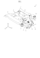
- FIG. 1 is a perspective view showing a rear suspension device according to an embodiment of the present invention
- FIG. 2 is a plan view of the rear suspension device of FIG. 1 as viewed from above the vehicle.
- FIG. 2 is a side view of the rear suspension device of FIG. 1 as viewed from the side of the vehicle.
- 2 is a rear view of the rear suspension device of FIG. 1 as seen from the rear of the vehicle.
- 2 is a plan view showing a schematic diagram of an upper link of the rear suspension device of FIG. 1 .
- 2 is a plan view showing a schematic diagram of a lower link of the rear suspension device of FIG. 1 .
- FIG. 5C is a rear view of FIG. 5B.
- the rear suspension device according to the present invention is a so-called independent suspension device that can raise and lower the left and right wheels independently, and is also a so-called multi-link suspension device that includes multiple links.
- the rear suspension device according to the present invention is also a rear suspension device that has a four-wheel steering mechanism and steers the rear wheels by only a small angle in response to steering operation of the steering wheel.
- the present invention will be described using a rear suspension device suspended between the left rear wheel and the vehicle body as an example, but a rear suspension device suspended between the right rear wheel and the vehicle body can also be configured in a similar manner.
- FIG. 1 is a perspective view of a rear suspension device 1 according to one embodiment of the present invention
- FIG. 2 is a plan view of the rear suspension device 1 of FIG. 1 as seen from above the vehicle
- FIG. 3 is a side view of the rear suspension device 1 of FIG. 1 as seen from the side of the vehicle
- FIG. 4 is a rear view of the rear suspension device 1 of FIG. 1 as seen from the rear of the vehicle.
- the illustration of the tires and wheels is omitted in FIG. 1 to FIG. 4, these tires and wheels are rotatably mounted on knuckles 31, which will be described later, and in the case of a rear-wheel drive vehicle, are connected to a drive shaft (not shown, only the wheel axle 32 is shown).
- the rear suspension device 1 of this embodiment is suspended between the vehicle body 2 and the wheels 3, and includes two upper links and three lower links, as well as a rear wheel steering actuator 18 of a four-wheel steering mechanism.
- the two upper links the one at the front of the vehicle is referred to as the first upper link 11, and the one at the rear of the vehicle is referred to as the second upper link 12.
- the three lower links the one at the front of the vehicle in the fore-and-aft direction is referred to as the first lower link 13, the one in the middle in the fore-and-aft direction of the vehicle is referred to as the second lower link 14, and the one at the rear of the vehicle in the fore-and-aft direction is referred to as the third lower link 15.
- a rod of the rear wheel steering actuator 18 is connected to one end of the third lower link 15.
- the first upper link 11, the second upper link 12, the first lower link 13, the second lower link 14, and the third lower link 15 are rigid bodies made of processed steel plate, cast products, forged products, or the like. Rubber bushings (detailed illustration omitted) are interposed at both ends of the first upper link 11, the second upper link 12, the first lower link 13, and the second lower link 14, one end of which is swingably attached to a bracket provided on the vehicle body 2, and the other end of which is swingably attached to the knuckle 31 of the wheel 3.
- one end of the third lower link 15 is connected to the rod of the rear wheel steering actuator 18, and the other end of which is swingably attached to the knuckle 31 of the wheel 3.
- the vehicle body 2 to which the first upper link 11, the second upper link 12, the first lower link 13, and the second lower link 14 are attached, as well as the rear wheel steering actuator 18, includes a rear side member and a rear suspension member 21 fixed to the rear floor via a rubber bushing 211.
- the first upper link 11, the second upper link 12, the first lower link 13, and the second lower link 14 are attached to the rear suspension member 21 so as to be swingable, but some or all of them may be attached to the rear side member or the like so as to be swingable.
- the rear suspension device 1 of this embodiment comprises, in order from the front of the vehicle, a first lower link 13, a second lower link 14, and a third lower link 15.
- the ends of the first lower link 13 and the second lower link 14 on the wheel 3 side are swingably attached to the lower part of the knuckle 31 via rubber bushings
- the ends on the vehicle body 2 side are swingably attached to the lower part of the rear suspension member 21 via rubber bushings.
- the end of the third lower link 15 on the wheel 3 side is swingably attached to the center of the knuckle 31 via a rubber bushing, as shown in Figure 4, and the end on the vehicle body 2 side is connected to the rod of the rear wheel steering actuator 18.
- the rear wheel steering actuator 18 in this embodiment is composed of, for example, a hydraulic cylinder, and the rod moves forward and backward by controlling the hydraulic system.
- the rod of the rear wheel steering actuator 18 is connected to the end of the third lower link 15 on the vehicle body 2 side, and the main body of the rear wheel steering actuator 18 is attached to the vehicle body 2, such as the rear suspension member 21, so that when the rear wheel steering actuator 18 is operated, the rear end of the knuckle 31 to which the other end of the third lower link 15 is attached rotates a predetermined angle. This causes the rear wheels to turn.
- the rear suspension device 1 of this embodiment further includes a shock absorber 16 and a spring 17.
- the lower end of the shock absorber 16 of this embodiment is swingably attached to the first lower link 13 as shown in Figures 1 and 3, and the upper end is attached to the vehicle body 2 (not shown).
- the lower end of the spring 17 of this embodiment is attached to the second lower link 14 as shown in Figures 2 to 4, and the upper end is attached to the vehicle body 2 (not shown).
- the rear suspension device 1 of this embodiment includes a first upper link 11 and a second upper link 12 as I-type upper links.
- the ends of the first upper link 11 and the second upper link 12 on the wheel 3 side are swingably attached to the top of the knuckle 31 via rubber bushings, and the ends on the vehicle body 2 side are swingably attached to the bottom of the rear suspension member 21 via rubber bushings.
- FIG. 5A is a plan view showing the first upper link 11 and the second upper link 12 of the rear suspension device 1 of this embodiment
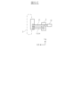
- FIG. 5B is a plan view showing the first lower link 13, the second lower link 14, the third lower link 15, and the rear wheel steering actuator 18 of the rear suspension device 1 of this embodiment.
- the hardness of the rubber bushings for example, is set so that the stiffness of the first upper link 11 and the stiffness of the second upper link 12 are different values.
- the stiffness of the upper link located farthest from the third lower link 15, on which the rear wheel steering actuator 18 is provided, in a plan view of the vehicle, is set relatively high.
- the rear wheel steering actuator 18 of the four-wheel steering mechanism is connected to the lower link that is farthest from the upper link with the relatively high stiffness among the three lower links.
- the rear wheel steering actuator 18 When the rear wheels are not steered, the rear wheel steering actuator 18 becomes a rigid rod in the toe direction, so by placing the rear wheel steering actuator 18 on the lower link (in this example, the third lower link 15) that is the furthest away from the upper link (in this example, the first upper link 11) that has the relatively higher rigidity of the two upper links, the fore-and-aft distance between the support points with the highest rigidity among the support points that support the force in the toe direction is maximized. This improves toe rigidity when the rear wheels are not steered, improving the vehicle's straight-line performance.
- the hardness of the rubber bushings is set so that the stiffness of one upper link is higher or lower than that of the other upper link. Increasing the hardness of the rubber bushings increases their stiffness, and the stiffness of the upper link can be increased. Conversely, decreasing the hardness of the rubber bushings decreases their stiffness, and the stiffness of the upper link can be decreased. Note that the means for making the stiffness of one upper link different from that of the other upper link is not limited to setting the stiffness of the rubber bushings, but the stiffness of the upper link body may be made different by varying the shape or material of the upper link.
- the stiffness of the upper link refers to the degree to which it is difficult to deform in response to a force input to the upper link; when the deformation in response to the input is small, the stiffness is said to be high, and when the deformation is large, the stiffness is said to be low.
- the first upper link 11 and the second upper link 12 is set to have a relatively higher rigidity, and either rigidity may be set to be relatively higher.
- first upper link 11 located at the front in the vehicle's fore-and-aft direction is set to be higher than the rigidity of the second upper link 12 located at the rear in the vehicle's fore-and-aft direction.
- the virtual kingpin axis tilts toward the first upper link 11, which is the more rigid of the two upper links, so the virtual kingpin axis tilts forward. This ensures a sufficient distance between the ground contact position directly below the center of the tire and the intersection of the virtual kingpin axis with the ground, i.e., the caster rail, and shifts the point at which lateral force is generated in the tire backward, reducing the offset between the point at which lateral force is generated in the tire and the virtual kingpin axis. This reduces the required thrust of the rear wheel steering actuator 18, further preventing the size from increasing.
- the intersection of the virtual kingpin axis with the ground is located rearward of the axis of rotation of the vehicle.
- FIG. 5C is a rear view of FIG. 5B, and is a diagram showing a schematic diagram for easy understanding of the relationship of the mounting positions in the height direction of the first lower link 13, the second lower link 14, and the third lower link 15.
- the center of rotation of the rear suspension device 1 is set in front of the wheel 3 to suppress changes in posture during braking.
- the axle rotates counterclockwise when viewed from the left side of the vehicle, so the stroke amount of the second lower link 14 is greater than the stroke amount of the first lower link 13. Therefore, if a shock absorber 16 is provided on the second lower link 14, the required stroke amount becomes longer, and the overall length of the shock absorber 16 needs to be increased, which results in the problem that the mounting position of the upper end of the shock absorber 16 becomes higher, narrowing the luggage compartment of the cabin.
- a shock absorber 16 is provided on the first lower link 13, which is the frontmost in the vehicle's fore-and-aft direction
- a spring 17 is provided on the second lower link 14, which is in the center in the vehicle's fore-and-aft direction
- a rear wheel steering actuator 18 is provided on the third lower link 15, which is the rearmost in the vehicle's fore-and-aft direction.
- the lower end of the shock absorber 16 may be attached to an axle such as the knuckle 31 via a rubber bushing so that it can swing.
- an axle such as the knuckle 31
- a rubber bushing so that it can swing.
- Reference Signs List 1 rear suspension device 11: first upper link 12: second upper link 13: first lower link 14: second lower link 15: third lower link 16: shock absorber 17: spring 18: rear wheel steering actuator 2: vehicle body 21: rear suspension member 3: wheel 31: knuckle 32: wheel axle
Landscapes
- Engineering & Computer Science (AREA)
- Mechanical Engineering (AREA)
- Chemical & Material Sciences (AREA)
- Combustion & Propulsion (AREA)
- Transportation (AREA)
- Vehicle Body Suspensions (AREA)
Priority Applications (4)
| Application Number | Priority Date | Filing Date | Title |
|---|---|---|---|
| PCT/JP2023/002019 WO2024157339A1 (ja) | 2023-01-24 | 2023-01-24 | リヤサスペンション装置 |
| CN202380092066.5A CN120569301A (zh) | 2023-01-24 | 2023-01-24 | 后悬架装置 |
| EP23918062.3A EP4656417A1 (en) | 2023-01-24 | 2023-01-24 | Rear suspension device |
| JP2024572556A JPWO2024157339A1 (https=) | 2023-01-24 | 2023-01-24 |
Applications Claiming Priority (1)
| Application Number | Priority Date | Filing Date | Title |
|---|---|---|---|
| PCT/JP2023/002019 WO2024157339A1 (ja) | 2023-01-24 | 2023-01-24 | リヤサスペンション装置 |
Publications (1)
| Publication Number | Publication Date |
|---|---|
| WO2024157339A1 true WO2024157339A1 (ja) | 2024-08-02 |
Family
ID=91970053
Family Applications (1)
| Application Number | Title | Priority Date | Filing Date |
|---|---|---|---|
| PCT/JP2023/002019 Ceased WO2024157339A1 (ja) | 2023-01-24 | 2023-01-24 | リヤサスペンション装置 |
Country Status (4)
| Country | Link |
|---|---|
| EP (1) | EP4656417A1 (https=) |
| JP (1) | JPWO2024157339A1 (https=) |
| CN (1) | CN120569301A (https=) |
| WO (1) | WO2024157339A1 (https=) |
Citations (8)
| Publication number | Priority date | Publication date | Assignee | Title |
|---|---|---|---|---|
| JPH0214907A (ja) * | 1988-07-01 | 1990-01-18 | Mitsubishi Motors Corp | 独立懸架式リアサスペンション構造 |
| JPH0490910A (ja) * | 1990-08-06 | 1992-03-24 | Honda Motor Co Ltd | 車輪懸架装置 |
| JPH0664427A (ja) * | 1992-08-17 | 1994-03-08 | Nissan Motor Co Ltd | 車両用サスペンション装置 |
| JPH06508080A (ja) * | 1991-03-14 | 1994-09-14 | ドクトル インジエニエール ハー ツエー エフ ポルシエ アクチエンゲゼルシヤフト | サスペンション |
| JP4195208B2 (ja) | 2001-10-03 | 2008-12-10 | 日産自動車株式会社 | リヤサスペンション装置 |
| JP2009090762A (ja) * | 2007-10-05 | 2009-04-30 | Nissan Motor Co Ltd | サスペンション装置 |
| JP2009149296A (ja) * | 2007-12-21 | 2009-07-09 | Dr Ing Hcf Porsche Ag | 自動車のリヤホイールのためのホイールサスペンション |
| JP2015155252A (ja) * | 2014-02-20 | 2015-08-27 | マツダ株式会社 | 自動車のリヤサブフレーム構造 |
-
2023
- 2023-01-24 JP JP2024572556A patent/JPWO2024157339A1/ja active Pending
- 2023-01-24 EP EP23918062.3A patent/EP4656417A1/en not_active Withdrawn
- 2023-01-24 CN CN202380092066.5A patent/CN120569301A/zh active Pending
- 2023-01-24 WO PCT/JP2023/002019 patent/WO2024157339A1/ja not_active Ceased
Patent Citations (8)
| Publication number | Priority date | Publication date | Assignee | Title |
|---|---|---|---|---|
| JPH0214907A (ja) * | 1988-07-01 | 1990-01-18 | Mitsubishi Motors Corp | 独立懸架式リアサスペンション構造 |
| JPH0490910A (ja) * | 1990-08-06 | 1992-03-24 | Honda Motor Co Ltd | 車輪懸架装置 |
| JPH06508080A (ja) * | 1991-03-14 | 1994-09-14 | ドクトル インジエニエール ハー ツエー エフ ポルシエ アクチエンゲゼルシヤフト | サスペンション |
| JPH0664427A (ja) * | 1992-08-17 | 1994-03-08 | Nissan Motor Co Ltd | 車両用サスペンション装置 |
| JP4195208B2 (ja) | 2001-10-03 | 2008-12-10 | 日産自動車株式会社 | リヤサスペンション装置 |
| JP2009090762A (ja) * | 2007-10-05 | 2009-04-30 | Nissan Motor Co Ltd | サスペンション装置 |
| JP2009149296A (ja) * | 2007-12-21 | 2009-07-09 | Dr Ing Hcf Porsche Ag | 自動車のリヤホイールのためのホイールサスペンション |
| JP2015155252A (ja) * | 2014-02-20 | 2015-08-27 | マツダ株式会社 | 自動車のリヤサブフレーム構造 |
Also Published As
| Publication number | Publication date |
|---|---|
| CN120569301A (zh) | 2025-08-29 |
| JPWO2024157339A1 (https=) | 2024-08-02 |
| EP4656417A1 (en) | 2025-12-03 |
Similar Documents
| Publication | Publication Date | Title |
|---|---|---|
| US5498018A (en) | Wheel suspension | |
| WO2022081613A1 (en) | Suspension system | |
| US11571939B2 (en) | Suspension system | |
| US5499839A (en) | Wheel suspension system with elastokinematic wheel adjustment | |
| CN109476355B (zh) | 带反应式约束悬架的具有三个或更多个倾斜的车轮的车辆 | |
| GB2130979A (en) | Vehicle suspensions | |
| CN115703317B (zh) | 车辆的悬架装置 | |
| JPS6226921B2 (https=) | ||
| JPH10109510A (ja) | フロントサスペンション装置 | |
| JP2518349B2 (ja) | 車輌用リヤサスペンション | |
| JP4939310B2 (ja) | ストラット式サスペンション装置 | |
| CN110696916A (zh) | 用于生成正阿克曼的车轮转向设备 | |
| WO2024157339A1 (ja) | リヤサスペンション装置 | |
| JPH01190511A (ja) | 車両のサスペンション装置 | |
| JP4370518B2 (ja) | 自動車のフロントサスペンション装置 | |
| JP5237474B2 (ja) | ストラット式サスペンション装置 | |
| WO2024157340A1 (ja) | リヤサスペンション装置 | |
| EP1910108B1 (en) | Individual wheel suspension | |
| JP2022114514A (ja) | 車両懸架システム | |
| US20260091640A1 (en) | Vehicle steering device | |
| JPH02283509A (ja) | マクファーソンストラット型サスペンション | |
| JPH0694245B2 (ja) | 自動車のサスペンシヨン | |
| JPS6256001B2 (https=) | ||
| CN121291016A (zh) | 一种布置紧凑的梯形臂式后悬架系统及车辆 | |
| CN121268474A (zh) | 一种悬架结构及车辆 |
Legal Events
| Date | Code | Title | Description |
|---|---|---|---|
| 121 | Ep: the epo has been informed by wipo that ep was designated in this application |
Ref document number: 23918062 Country of ref document: EP Kind code of ref document: A1 |
|
| ENP | Entry into the national phase |
Ref document number: 2024572556 Country of ref document: JP Kind code of ref document: A |
|
| WWE | Wipo information: entry into national phase |
Ref document number: 2024572556 Country of ref document: JP |
|
| WWE | Wipo information: entry into national phase |
Ref document number: 202380092066.5 Country of ref document: CN |
|
| NENP | Non-entry into the national phase |
Ref country code: DE |
|
| WWP | Wipo information: published in national office |
Ref document number: 202380092066.5 Country of ref document: CN |
|
| WWP | Wipo information: published in national office |
Ref document number: 2023918062 Country of ref document: EP |