WO2024154401A1 - 制御デバイス、方法、およびコンピュータプログラム製品 - Google Patents
制御デバイス、方法、およびコンピュータプログラム製品 Download PDFInfo
- Publication number
- WO2024154401A1 WO2024154401A1 PCT/JP2023/038267 JP2023038267W WO2024154401A1 WO 2024154401 A1 WO2024154401 A1 WO 2024154401A1 JP 2023038267 W JP2023038267 W JP 2023038267W WO 2024154401 A1 WO2024154401 A1 WO 2024154401A1
- Authority
- WO
- WIPO (PCT)
- Prior art keywords
- obstacle
- parameters
- parameter
- measuring device
- control device
- Prior art date
- Legal status (The legal status is an assumption and is not a legal conclusion. Google has not performed a legal analysis and makes no representation as to the accuracy of the status listed.)
- Ceased
Links
Images


Classifications
-
- G—PHYSICS
- G08—SIGNALLING
- G08G—TRAFFIC CONTROL SYSTEMS
- G08G1/00—Traffic control systems for road vehicles
- G08G1/16—Anti-collision systems
- G08G1/166—Anti-collision systems for active traffic, e.g. moving vehicles, pedestrians, bikes
-
- B—PERFORMING OPERATIONS; TRANSPORTING
- B60—VEHICLES IN GENERAL
- B60W—CONJOINT CONTROL OF VEHICLE SUB-UNITS OF DIFFERENT TYPE OR DIFFERENT FUNCTION; CONTROL SYSTEMS SPECIALLY ADAPTED FOR HYBRID VEHICLES; ROAD VEHICLE DRIVE CONTROL SYSTEMS FOR PURPOSES NOT RELATED TO THE CONTROL OF A PARTICULAR SUB-UNIT
- B60W30/00—Purposes of road vehicle drive control systems not related to the control of a particular sub-unit, e.g. of systems using conjoint control of vehicle sub-units
- B60W30/08—Active safety systems predicting or avoiding probable or impending collision or attempting to minimise its consequences
- B60W30/09—Taking automatic action to avoid collision, e.g. braking and steering
-
- G—PHYSICS
- G06—COMPUTING OR CALCULATING; COUNTING
- G06V—IMAGE OR VIDEO RECOGNITION OR UNDERSTANDING
- G06V20/00—Scenes; Scene-specific elements
- G06V20/50—Context or environment of the image
- G06V20/56—Context or environment of the image exterior to a vehicle by using sensors mounted on the vehicle
- G06V20/58—Recognition of moving objects or obstacles, e.g. vehicles or pedestrians; Recognition of traffic objects, e.g. traffic signs, traffic lights or roads
Definitions
- the subject matter relates to a control device, method, and computer program product for controlling a driver assistance system for a vehicle.
- ADAS advanced driver assistance systems
- V2X vehicle-to-everything
- Patent Document 1 describes a system and apparatus for detecting a moving object that enters the field of view of a vehicle's camera device.
- This system uses location information obtained from a positioning device mounted on the vehicle itself, and location information periodically received from a mobile terminal carried by the moving object.
- a moving object enters the field of view of the camera, based on the location information of the mobile terminal of the moving object and the traveling direction of the vehicle itself, an area for detecting the moving object is set in the image captured by the camera, and the moving object is detected.
- V2X information e.g., taking into account the specifications and scope of application of the external device
- a control device, a method and a computer program product are proposed for controlling a driver assistance system for a vehicle.
- the subject matter disclosed herein improves the characteristics of the driver assistance system when an obstacle suddenly appears in the area surrounding the vehicle.
- the driver assistance system controlled by the disclosed subject matter may be, for example, Automatic Emergency Braking (AEB), Adaptive Cruise Control (ACC), or Lane Change Assist (LCA). Other types of driver assistance systems may also be combined with the proposed subject matter.
- AEB Automatic Emergency Braking
- ACC Adaptive Cruise Control
- LCDA Lane Change Assist
- the control device includes a first obstacle parameter acquisition unit configured to receive a plurality of first obstacle parameters of obstacles in an area (periphery that may include a range from centimeters to multiple meters and up to several kilometers) surrounding the vehicle detected by the first measurement device, the plurality of first obstacle parameters including one or more parameters of a first category and one or more parameters of a second category.
- a first obstacle parameter acquisition unit configured to receive a plurality of first obstacle parameters of obstacles in an area (periphery that may include a range from centimeters to multiple meters and up to several kilometers) surrounding the vehicle detected by the first measurement device, the plurality of first obstacle parameters including one or more parameters of a first category and one or more parameters of a second category.
- the first measuring device may be a radar (radio detection and ranging) sensor, a camera sensor, a lidar (light detection and ranging) sensor, a sonar (sound wave navigation and ranging) sensor, a GNSS (global navigation satellite system) sensor, or any other sensor suitable for detecting obstacles in the area surrounding the vehicle.
- the first measuring device may be connected to the vehicle or integrated or part of it.
- the obstacle may be, for example, a pedestrian, a bicycle, another vehicle, or any other object that appears around the vehicle as the vehicle travels along the road.
- the plurality of first obstacle parameters may include, for example, the obstacle type (bicycle, pedestrian, etc.), position, heading, speed, yaw rate, and acceleration of the obstacle detected by the first measuring device, or any other type of parameter describing the characteristics of the obstacle.
- the first measuring device (also referred to as a sensor or on-board sensor or on-board device) may be part of the control device or may be external to the control device.
- the control device may receive signals/data from the first measuring device, which may be provided at a different location/position of the vehicle in case of a separate control unit or a control unit integrated with another control unit of the vehicle.
- the first measuring device may be integrated with the control device as described herein, and in a further modification, the first obstacle parameter acquisition unit and the first measuring device may be integrated with each other as a single unit, whereby the functions of the two units described in this disclosure may be performed by said integrated single unit.
- a first obstacle parameter is to be understood as a parameter of an object detected by a first measuring device.
- the plurality of first obstacle parameters may be divided into a first group comprising one or more parameters of a first category and a second group comprising one or more parameters of a second category.
- the categories of parameters may be defined, for example, by features/attributes/characteristics that one parameter may have in common with another parameter.
- control device comprises a second obstacle parameter acquisition unit configured to receive a plurality of second obstacle parameters of obstacles in the area surrounding the vehicle detected by the second measurement device.
- the second measurement device (or sensor or external sensor) is provided outside the vehicle where the first measurement device is located.
- the plurality of second obstacle parameters includes one or more parameters of the first category and one or more parameters of the second category.
- the second obstacle parameter acquisition unit is part of the control device described herein and preferably receives data/signals from the second measurement device and forwards them to a next unit, preferably an obstacle parameter calculation unit, at least in order to receive them in the control device.
- the second measurement device located outside the vehicle where the first measurement device and/or the control device are provided as described herein may directly transmit the second obstacle parameters to the obstacle parameter calculation unit.
- the second obstacle parameters are to be understood as parameters of the detected obstacle determined/detected/measured by the second measuring device or the second obstacle parameter acquisition unit.
- the plurality of second obstacle parameters may further include, for example, the obstacle type, position, direction (heading), speed, yaw rate and acceleration detected by the first measuring device, or any other kind of parameters describing the characteristics of the obstacle, and may be further divided into a first group including one or more parameters of the first category and a second group including one or more parameters of the second category.
- the second measuring device may determine the same parameters of the first and second categories as the first measuring device.
- the second measuring device may further be a radar sensor, a camera sensor, a lidar sensor, a sonar sensor, a GNSS sensor or any other sensor suitable for detecting obstacles in the area surrounding the vehicle.
- the second measuring device may be the same sensor type as the first measuring device or a different sensor type.
- the second measuring device may be located at a different location than the first measuring device and thereby detect obstacles at a different time than the first measuring device.
- the second measuring device may be located to detect obstacles earlier than the first measuring device.
- the second measuring device is provided remotely from the vehicle, i.e. it is not integrated or located on the vehicle but is external to the vehicle.
- the one or more parameters of the first category may preferably be parameters that can be determined/measured/detected by the first measuring device (or the first obstacle parameter acquisition unit) with greater certainty than the second measuring device (or the second obstacle parameter acquisition unit).
- the one or more parameters of the second category may preferably be parameters that can be determined/measured/detected with greater certainty by the second measuring device.
- the second measuring device may already receive a number of obstacle parameters before the first measuring device (or the first obstacle parameter acquisition unit) receives the first obstacle parameter. Due to the longer observation time of the obstacle resulting from the successive reception of the obstacle parameters, the parameters that remain constant over the observation time may be determined with greater accuracy by the second measuring device.
- the characteristics of the two measuring devices may differ. This may further result in the first measuring device being able to determine the parameters of the first category with greater accuracy, and the second measuring device being able to determine the parameters of the second category with greater accuracy.
- control device includes an obstacle parameter calculation unit that receives a plurality of first and second obstacle parameters from the first and second obstacle parameter acquisition units, and calculates a plurality of third obstacle parameters including one or more parameters of a first category and one or more parameters of a second category based on the plurality of first and second obstacle parameters.
- the obstacle parameter calculation unit uses the first and second obstacle parameters determined by the first and second measuring devices (or the obstacle parameter acquisition unit) to calculate a new set of third obstacle parameters.
- the new set of third obstacle parameters further includes one or more parameters of a first category and one or more parameters of a second category.
- the obstacle parameter calculation unit calculates one or more parameters of the first category based on the first obstacle parameters and one or more parameters of the second category based on the second obstacle parameters.
- the obstacle parameter calculation unit obtains from the plurality of first obstacle parameters a first category of parameters that can be determined with greater certainty by a first measuring device (or a first obstacle parameter acquisition unit) and from the plurality of second obstacle parameters a second category of parameters that can be determined with greater certainty by a second measuring device (or a second obstacle parameter acquisition unit) in order to calculate a new set of third obstacle parameters.
- the obstacle parameter calculation unit can calculate the multiple third obstacle parameters with high accuracy. This also means that the obstacle parameter calculation unit can provide multiple reliable obstacle parameters earlier compared to calculations based only on one measurement device, which takes longer to obtain reliable values for each obstacle parameter.
- the control device may include first and second obstacle parameter acquisition units that receive the first and second obstacle parameters from the first and second measuring devices.
- These obstacle parameter acquisition units may, for example, perform processing (e.g., smoothing, filtering, averaging) of the first and second obstacle parameters determined by the first and second measuring devices before they are sent to the obstacle parameter calculation unit.
- those obstacle parameter acquisition units may also be configured to detect/determine and/or select parameters of interest of the obstacles detected by the first or second measuring devices.
- the first/second measuring devices may further be configured to detect obstacles
- the first/second obstacle parameter acquisition units may be configured to process the detection data from the first/second measuring devices to extract/obtain parameters used for further processing in the control device described herein.
- the first and second obstacle parameter acquisition units may further (simply) serve as receiving and parameter forwarding units in the control device.
- control device includes an enable unit (which may also be referred to as a driving assistance enablement determination unit or a driving assistance enabling unit, etc.) that calculates a first judgment parameter based on the plurality of third obstacle parameters received from the obstacle parameter calculation unit, and enables the driving assistance if the judgment parameter is smaller than a predetermined activation threshold.
- the obstacle parameter calculation unit transmits the plurality of third obstacle parameters to the enable unit, and the enable unit derives comparison data (judgment parameters) from the third obstacle parameters to determine whether to enable the driving assistance.
- the driving assistance may be, for example, automatic braking, acceleration, or steering. Alternatively or additionally, the driving assistance may also be an auditory or visual signal prompting the driver to perform a certain action, such as braking, deceleration, etc.
- the enable unit compares the decision parameter with a predetermined activation threshold and enables the driving assistance if the decision parameter is below the threshold. For example, the enable unit may calculate the time until the vehicle reaches the obstacle (time-to-collision) or the difference between the vehicle and the obstacle as the decision parameter based on the third obstacle parameter.
- the predetermined activation threshold in this case may be a predetermined time or a predetermined distance.
- the enabling unit When the enabling unit derives the first decision parameter from a plurality of third obstacle parameters that are based on the most probable obstacle parameters received from the first and second measuring units, the enabling unit can determine the first decision parameter early and with high accuracy. This allows the control device to activate the driving assistance before the obstacle appears next to the vehicle, thus avoiding abrupt driving movements and increasing driving comfort.
- control device may further comprise an enabling unit that may enable the driving assistance based on the enable signal received from the enabling unit.
- the enabling unit may send an enable signal to the enabling unit, which then enables actuators/control elements for the driving assistance in the vehicle, such as hydraulic valves for braking or steering actuation and/or signal outputs for providing audio or visual information.
- actuators/control elements for the driving assistance in the vehicle such as hydraulic valves for braking or steering actuation and/or signal outputs for providing audio or visual information.
- the actuators may be directly enabled by the enabling unit.
- the obstacle parameter calculation unit may determine whether the first and second measuring devices have detected the same (identical) obstacle based on a comparison result of at least one of the first and second obstacle parameters, and may calculate the third obstacle parameters only if the determination result is positive, i.e., only if the obstacles detected by the first and second measuring devices are identical.
- the obstacle parameter calculation unit may first determine whether the first and second obstacle parameters include the same obstacle type, e.g., whether both measuring devices detect a bicycle. If so, the obstacle parameter calculation unit may calculate a distance between the obstacle location included in the first obstacle parameter and the obstacle location included in the second obstacle parameter. If the calculated distance is less than a predetermined distance threshold, the obstacle parameter calculation unit may recognize the obstacles detected by both measuring devices as the same object. In case of a positive result, i.e., the same, the obstacle parameter calculation unit may use the first and second obstacle parameters to calculate a third obstacle parameter as described above. In case of a negative result, i.e., not the same, the obstacle parameter calculation unit may receive a further first and/or second obstacle parameter from the first and/or second measuring device and repeat the process until a positive result is obtained.
- the obstacle parameter calculation unit may receive a further first and/or second obstacle parameter from the first and/or second measuring device and repeat the process until a positive result is obtained.
- the first measuring device may be a measuring device that can communicate with the obstacle parameter calculation unit (or the first obstacle parameter acquisition unit) faster than the second measuring device, but can detect obstacles later than the second measuring device.
- the second measuring device may be a measuring device that can detect obstacles earlier than the first measuring device, but can communicate with the obstacle parameter calculation unit (or the second obstacle parameter acquisition unit) slower/over a longer communication path than the first measuring device.
- the first measuring device may be an on-board measuring device located inside the vehicle, while the second measuring device is an external measuring device located outside the vehicle.
- the communication between the on-board measuring device and the control device described herein (or the first obstacle parameter acquisition unit) may be performed in real time or with low latency, while the communication between the external measuring device and the control device described herein may be performed, for example, via a cellular network with longer latency periods.
- the on-board measuring device may be a radar sensor, a camera sensor, a lidar sensor, a sonar sensor, a GNSS sensor or any other sensor as an on-board sensor for the vehicle.
- a combination of radar, camera, lidar, sonar and GNSS sensors may be mounted on the vehicle.
- each of those sensors can only detect an obstacle when it appears in the field of view, i.e. when the obstacle is not obstructed by another obstacle in the vicinity of the vehicle.
- a second external device capable of detecting an obstacle early can provide useful second obstacle parameters for a driving assistance that can be activated/enabled at an early stage, rather than suddenly.
- the external measuring device may be, for example, a roadside unit, which may detect obstacles, for example via radar and/or camera sensors.
- the roadside unit may be configured to exchange information with obstacles equipped with their own on-board measuring devices, such as other vehicles and pedestrians/cyclists carrying mobile devices.
- the latter i.e. other vehicles with on-board measuring devices and mobile devices (smartphones, tablets, laptops), may also be external measuring devices suitable as second measuring devices.
- another vehicle in the vicinity of the vehicle may be an obstacle providing information about its own state, such as current position, speed and heading, and/or may be the only measuring device providing information about another obstacle in the vicinity of the vehicle detected by its own on-board measuring device.
- the second measuring device may be an on-board measuring device of another vehicle proceeding as a potential obstacle around the vehicle.
- the obstacle parameter calculation unit may receive the width and height of the other vehicle as a further second obstacle parameter, which further obstacle parameter may be taken into account when calculating the plurality of third obstacle parameters.
- the obstacle parameter calculation unit may use the width and height of the vehicle to determine its spatial position coordinates. Knowing the spatial position coordinates of the obstacle subsequently allows the enabling unit to determine the collision distance and/or collision margin to the obstacle with greater accuracy.
- both, i.e. the first and second measuring devices are external devices located outside the vehicle.
- the measuring device located closer to the vehicle may act as the first measuring device and the measuring device located further away from the vehicle may act as the second measuring device.
- the measuring device closer to the vehicle has a shorter latency period than the measuring device located further away.
- the measuring device located further away from the vehicle may detect an obstacle earlier than the measuring device located closer.
- a roadside unit immediately to the right of the vehicle may act as a first measuring device, and if a pedestrian with a smartphone appears as an obstacle around the vehicle, the pedestrian's smartphone may act as a second measuring device.
- the control device may receive signals from each external measuring device and determine which measuring device should act as the first and second measuring device, for example, depending on the signal strength.
- the obstacle parameter calculation unit may then receive the first and second obstacle parameters from both external devices (preferably via the first/second obstacle parameter acquisition unit) and calculate a third obstacle parameter based on the parameter with the highest certainty.
- the obstacle parameter calculation unit may receive, for example, the position of the pedestrian from the roadside unit as a first obstacle parameter. Meanwhile, since the speed of the pedestrian can be assumed to be approximately constant in the observed time slot, the obstacle parameter calculation unit may receive, for example, the speed of the pedestrian from the pedestrian's smartphone as a second obstacle parameter. If the smartphone determines the speed of the pedestrian over a much longer period of time than the roadside unit, the accuracy and certainty of the determination are increased.
- the first category of parameters may be obstacle position parameters comprising static information about the obstacle
- the second category of parameters may be obstacle movement parameters comprising dynamic information about the obstacle.
- the static information about the obstacle may be, for example, the type of obstacle (pedestrian, cyclist, vehicle, etc.), the current time (timestamp) at which the obstacle was detected, and its current position and heading.
- the static information is characterized by facts that are time-independent with respect to the time of acquisition.
- the dynamic information about the obstacle may be, for example, its speed, yaw rate, and acceleration.
- the dynamic information is characterized by facts that are time-dependent with respect to the time of acquisition.
- the first measuring device can provide multiple first obstacle parameters within a short latency period, so that the obstacle parameter calculation unit can calculate multiple third position parameters using the position parameters received from the first measuring device.
- the movement parameters such as the speed, acceleration and yaw rate of the obstacle may be assumed to remain constant within the observed time slot. Therefore, the time of transmission of the movement parameters to the obstacle parameter calculation unit may be less important than the transmission of the position parameters.
- the certainty of the obstacle parameters increases with each determination, i.e. the earlier a certain obstacle parameter can be determined, the more accurate and certain it is. Since the second measuring device can detect the obstacle earlier than the first measuring device, the obstacle parameter calculation unit may calculate a number of third position parameters using the movement parameters received from the second measuring device.
- the obstacle parameter calculation unit is able to calculate multiple third obstacle parameters, based on which driving assistance can be activated using the first and second obstacle parameters with the highest accuracy and reliability.
- the obstacle parameter calculation unit may include a predictive model for calculating the plurality of third obstacle parameters, and the predictive model may calculate the plurality of third obstacle parameters when an obstacle is first detected using one or more parameters of a second category from the plurality of second obstacle parameters as one or more initial parameters.
- the predictive model may use the movement parameters of the plurality of second obstacle parameters to initialize the predictive model.
- the predictive model may start the calculation with already certain values of, for example, speed, acceleration, and yaw rate, improving the accuracy of the prediction.
- the predictive model may include a Kalman filter for calculating the plurality of third obstacle parameters based on the plurality of first and second obstacle parameters determined by the first and second measuring devices.
- the obstacle parameter calculation unit may calculate a reliability index representative of the reliability of the plurality of third obstacle parameters and may transmit the calculated reliability index together with the third obstacle parameters to the enable unit.
- the reliability index may for example be a counter that may be incremented each time an event occurs that increases the reliability of the third obstacle parameter and decremented each time an event occurs that decreases the reliability of the third obstacle parameter.
- the enable unit may enable the activation of the driving assistance if the first decision value is lower than a predefined activation threshold and if the value of the reliability index is higher than a first predefined reliability threshold. This ensures that the driving assistance is only performed if the plurality of third obstacle parameters, on the basis of which a decision value for activating the driving assistance may be calculated, achieve sufficient reliability.
- the enable unit may further receive a plurality of first obstacle parameters and may calculate a second decision parameter based on the plurality of first obstacle parameters. In this case, the enable unit may enable the driving assistance if the first and/or second decision parameter is lower than a predefined activation threshold.
- the enable unit may calculate two decision parameters, where a first decision parameter is derived from a plurality of third obstacle parameters calculated by the obstacle parameter calculation unit based on the plurality of first and second obstacle parameters as described above, and a second decision parameter is derived only from the plurality of first obstacle parameters. Enabling the driving assistance if at least one of the two decision parameters is lower than a predefined threshold ensures that the driving assistance can be enabled with high certainty even if the control unit has access to only a first measuring device, such as an on-board sensor of the vehicle.
- the obstacle parameter calculation unit may increase the value of the reliability index based on the number of times the obstacle is detected by the first measuring device. Due to the high-speed communication path of the first measuring device, which presupposes stable signal transmission, the reliability of the plurality of first obstacle parameters may be considered to depend mainly on the observation time, i.e. the number of times the obstacle is detected by the first measuring device, which may be significantly shorter than the observation time of a second measuring device that detected the obstacle earlier.
- the obstacle parameter calculation unit may calculate a reliability index taking into account the specifications of a number of second obstacle parameters determined by the second measuring device. Since the second measuring device may be significantly further from the vehicle than the first measuring device, the impact of the obstacle parameter detection and transmission method may be significantly more significant than for the first measuring device. For example, if the second measuring device transmits a GNSS-based message, its accuracy may depend on the environment of the second measuring device, since GNSS cannot provide a signal, for example, in a tunnel.
- the specification of the plurality of second obstacle parameters may include information regarding the characteristics/properties/quality of the second obstacle parameters, including the characteristics/properties/quality of the second measurement device.
- the specification may include, for example, information regarding the sensor type of the second measurement device, the message type, the signal resolution, and the timestamp of the second measurement parameters, as well as any other information that delivers information regarding the characteristics/properties/quality of the second obstacle parameters.
- control device may comprise a specification acquisition unit for acquiring specifications of a plurality of second obstacle parameters before being sent to the obstacle parameter calculation unit.
- the specification acquisition unit may process the signal received from the second measuring device/second obstacle parameter acquisition unit to prepare it for the calculation performed by the obstacle parameter calculation unit.
- the obstacle parameter calculation unit may also be possible for the obstacle parameter calculation unit to receive the specifications of the second obstacle parameters directly.
- the specification of the second obstacle parameters may include a number of specification parameters, and the obstacle parameter calculation unit may adjust the value of the reliability index based on the value of each specification parameter.
- the specification parameters may include a number of pieces of information regarding boundary conditions under which the second obstacle parameters are determined. Based on this information, the obstacle parameter calculation unit may increment or decrement the value of the reliability index.
- the obstacle parameter calculation unit and/or the specification acquisition unit may receive a timestamp as a specification parameter from the second measuring device (or from the second obstacle parameter acquisition unit), providing the latest time at which the second measuring device determined the second obstacle parameter.
- the obstacle parameter calculation unit may then calculate a delay time of the received second obstacle parameter and may decrease/decrement the value of the reliability index depending on the length of the delay time. In particular, a long delay time may result in a larger decrease in the value of the reliability index than a short delay time. If the delay time is shorter than a predefined threshold, the reliability level may remain constant.
- the predefined threshold for the delay time may, for example, correspond to the delay time of the first measuring device.
- the obstacle parameter calculation unit and/or the specification acquisition unit may acquire the number of times that the second measurement device (second obstacle parameter acquisition unit) determined the second obstacle parameter (observation length) as a specification parameter, and the obstacle parameter calculation unit may decrease/decrement the value of the reliability index depending on the observation length.
- a short observation length may result in a larger decrease in the value of the reliability index than a long observation time. If the observation length is above a predefined threshold, the reliability level may remain constant.
- the obstacle parameter calculation unit and/or the specification acquisition unit may receive as a specification parameter a variance of a determined second obstacle parameter, such as, for example, a variance of a determined speed signal of the obstacle.
- the obstacle parameter calculation unit may decrease/decrement the value of the reliability index depending on the variance of the determined parameter, with a small variance resulting in a smaller decrease in the reliability index value than a large variance.
- the reliability level may remain constant.
- the obstacle parameter calculation unit and/or the specification acquisition unit may receive a message type of the second obstacle parameter as a specification parameter.
- Possible message categories may be, for example, cooperative perception messages from another vehicle providing information about itself, messages from a roadside unit, collective perception messages providing information about other objects from another vehicle, messages provided by a mobile device, and other messages that do not fall into one of the above categories.
- the obstacle parameter calculation unit may increase the value of the confidence index according to the order of the above message categories, with cooperative perception messages providing the highest confidence increase, while messages that do not fall into the above categories providing the lowest confidence increase.
- the obstacle parameter calculation unit and/or the specification acquisition unit may acquire the stability of communication with the second measuring device as a specification parameter and adjust the value of the reliability index based on the communication stability.
- the obstacle parameter calculation unit may, for example, determine the signal strength of the wireless communication around the vehicle and derive the communication stability with the second measuring unit from the signal strength. In particular, a high signal strength may indicate stable communication, and a low signal strength may indicate unstable communication.
- the obstacle parameter calculation unit and/or the specification acquisition unit may receive the activation status of the other vehicle's driving assistance system as a specification parameter and may increase/increment the value of the reliability index if the driving assistance system is enabled.
- Each of the specification parameters described above may contribute to the adjustment of the reliability index, i.e. the value of the reliability index may be the result of a combination of adjustments from multiple specification parameters.
- each or at least some of the specification parameters are weighted in view of their importance for a reliable calculation of the third obstacle parameter.
- specification parameters having a high importance for a correct calculation of the multiple third obstacle parameters may be weighted with a high coefficient
- specification parameters having a low importance for a correct calculation of the multiple third obstacle parameters may be weighted with a low coefficient.
- the obstacle parameter calculation unit or the specification acquisition unit may receive multiple map information of the area surrounding the vehicle and may adjust the value of the reliability index based on the multiple map information.
- This map information may be stored in a storage unit of the control device and may include, for example, information about building locations and traffic congestion, based on which the obstacle parameter calculation unit may conclude regarding the quality of the second obstacle parameter determined by the second measuring device.
- the assessment of the message type may be modified based on the map information.
- the obstacle parameter calculation unit may decrease the increase in the value of the reliability index based on a message from a roadside unit when a traffic congestion occurs immediately next to the roadside unit, where the obstacle may be blocked by other vehicles.
- the obstacle parameter calculation unit and/or the specification acquisition unit may additionally or alternatively determine the stability of the communication with the second measuring device from the information provided in the map information. For example, if the vehicle is driving through an area with tall buildings, the stability of the communication may be low since the buildings may interfere with the communication with the second measuring device. The same is true if the vehicle is driving in a busy area where data traffic may be very high.
- These environmental conditions derivable from the map information can be used to determine the communication stability between the obstacle parameter calculation unit and/or the specification acquisition unit (or the control device in general) and the second measuring device, and the obstacle parameter calculation unit can increase or decrease the value of the reliability index based on the respective condition.
- the second obstacle parameter acquisition unit may receive a plurality of second obstacle parameters from more than one second measuring device.
- the obstacle parameter calculation unit may select a plurality of second obstacle parameters received from the more than one second measuring device. For example, the obstacle parameter calculation unit may determine the order of the second measuring devices according to the message type of those second obstacle parameters. If the message received from the second measuring device is a cooperative perception message providing information that another vehicle is an obstacle, the other vehicle may be selected as a preferred second measuring device because the cooperative perception message is a message of high certainty.
- the environment of the other vehicle may also be taken into consideration when selecting a plurality of second obstacle parameters received from more than one second measuring device. If the other vehicle selected as a preferred second measuring device is traveling in a congested area, the transmission of the communication path to the obstacle parameter calculation unit may be disrupted. Therefore, the obstacle parameter calculation unit may also take into consideration the map information when determining the order of the second measuring devices.
- the obstacle parameter calculation unit may determine whether an obstacle detected by one second measuring device is identical to an obstacle detected by the other second measuring device based on at least one of the multiple second obstacle parameters of the one second measuring device and the other second measuring device.
- the obstacle parameter calculation unit may first determine whether the multiple second obstacle parameters from one second measuring device and the other second measuring device include the same obstacle type, e.g., whether both second measuring devices detect a bicycle. If so, the obstacle parameter calculation unit may calculate a distance between an obstacle position included in the second obstacle parameters of one second measuring device and an obstacle position included in the second obstacle parameters of the other second measuring device. If the calculated distance is less than a predetermined distance threshold, the obstacle parameter calculation unit may recognize the obstacles detected by both second measuring devices as the same object. In this case, the second obstacle parameter acquisition unit may receive the multiple second obstacle parameters from at least one of the second measuring devices.
- the second obstacle parameter acquisition unit may receive a plurality of second obstacle parameters from one of the second measuring devices detecting an obstacle identical to the obstacle detected by the first measuring device.
- the obstacle parameter calculation unit may increase the value of the reliability index if the obstacles detected by one and the other second measuring devices are identical, and may decrease the value of the reliability index if the obstacles detected by one and the other second measuring devices are different. If both second measuring devices detect the same obstacle, the certainty of the second obstacle parameters is high since they have been determined twice. However, if one and the other second measuring devices detect different obstacles, the certainty of the second obstacle parameters is low since it is not clear which of the two second measuring devices detected the obstacle of interest.
- the obstacle parameter calculation unit may receive the field of view of one and the other second measuring device and may decrease the value of the reliability index if the field of view of one second measuring device overlaps with the field of view of the other second measuring device.
- the overlapping fields of view may lead to inconsistent results regarding the obstacles detected by one and the other second measuring device. Therefore, the value of the reliability index is decreased if the fields of view of both second measuring devices overlap.
- the enabling unit may comprise an alert enabling unit which may calculate an alert decision parameter based on the plurality of third obstacle parameters and which may enable an alert as a driving assistance if the calculated alert decision parameter is smaller than a predefined alert enabling threshold.
- the enabling unit may comprise an intervention enabling unit which may calculate an intervention decision parameter based on the plurality of third obstacle parameters and which may enable an intervention as a driving assistance if the intervention decision parameter is smaller than a predefined intervention enabling threshold.
- the predefined alert enabling threshold may be larger than a predefined intervention enabling threshold.
- the alert enabling threshold may comprise a crash margin time value larger than the intervention enabling threshold. Thereby, the alert may be enabled earlier than the intervention.
- control device further comprises an enabling unit
- the enabling unit may further comprise an alert enabling unit that may enable an alert based on a determination of the alert enabling unit, and an intervention enabling unit configured to enable an intervention based on a determination of the intervention enabling unit.
- the obstacle parameter calculation unit may calculate a first plurality of third obstacle parameters and a second plurality of third obstacle parameters.
- the second predetermined reliability threshold may be equal to or greater than the first predetermined reliability threshold.
- the first plurality of third obstacle parameters may be calculated based on the plurality of first obstacle parameters and the plurality of second obstacle parameters
- the second plurality of third obstacle parameters may be calculated based only on the plurality of first obstacle parameters.
- the warning enable unit may calculate a warning decision parameter based on the first plurality of third obstacle parameters
- the intervention enable unit may calculate an intervention decision parameter based on the second plurality of third obstacle parameters. In other words, even if the reliability index is below the second predetermined threshold, a warning may be enabled based on a combination of a position parameter obtained from the plurality of first obstacle parameters and a movement parameter obtained from the plurality of second obstacle parameters.
- an intervention in the driver's driving behavior may be performed based only on the first obstacle parameters, which may preferably be determined by an on-board measurement device of the vehicle. This ensures that the entire control of the driving assistance system can remain with the vehicle in cases where the external measurement device may not be 100% reliable.
- the obstacle parameter calculation unit may only calculate the first plurality of third obstacle parameters, and the warning enable unit and the intervention enable unit may respectively calculate the warning decision parameter and the intervention decision parameter based on the first plurality of third obstacle parameters.
- the disclosed subject matter may further include a control system including a control device and a first and/or second measuring device as described above.
- the disclosed subject matter also includes a vehicle including a control device and at least a first measuring device as described above.
- the disclosed subject matter further includes a method for controlling a driving assistance system for a vehicle, wherein the first plurality of obstacle parameters of a detected obstacle includes one or more parameters of a first category and one or more parameters of a second category, and the second plurality of obstacle parameters of the detected obstacle includes one or more parameters of the first category and one or more parameters of the second category.
- the plurality of first and second obstacle parameters are received by the obstacle parameter calculation unit, and a plurality of third obstacle parameters of the detected obstacle are calculated by the obstacle parameter calculation unit, the plurality of third obstacle parameters including one or more parameters of a first category and one or more parameters of a second category based on the plurality of first and second obstacle parameters, the one or more parameters of the first category being calculated based on the plurality of first obstacle parameters, and the one or more parameters of the second category being calculated based on the plurality of second obstacle parameters.
- a judgment parameter based on the third plurality of obstacle parameters received from the obstacle parameter calculation unit is calculated by the enable unit, and if the judgment parameter is lower than a predetermined threshold, the enable unit enables driving assistance.
- the disclosed subject matter will be further described on the basis of several examples with reference to the attached drawings.
- the same elements are given the same reference signs and a repeated description of the same elements will be avoided.
- the figures show an embodiment that can be modified according to the above-mentioned embodiments and their further variants and/or according to the variants described in connection with the detailed description of the drawings.
- this applies to the separate or integrated provision of the first/second measuring device and/or the first/second obstacle parameter acquisition device and their respective adaptations to the data transmission/reception input and output.
- the measuring device and the obstacle parameter acquisition unit are provided as separate units, it is a preferred option to transmit information/data about the detected obstacles to the respective obstacle parameter acquisition unit.
- the said data may already contain the necessary parameters for further processing or may be itself, in which case the obstacle parameter acquisition unit mainly serves as an input unit of the control device and passes on the said data (or modified data) to a subsequent unit such as an obstacle parameter calculation unit.
- the data may also include raw detection data/information on the detected objects, in which case the obstacle parameter acquisition unit is configured to extract, select and/or determine the parameters of interest and the respective data and transmit it to a subsequent unit, such as an obstacle parameter calculation unit.
- the options can also be combined. Otherwise, if the measurement device and the respective obstacle parameter acquisition device are integrated in a combined or single unit, they may also perform the functions described above together.
- the first measurement device and the first obstacle parameter acquisition unit are combined, while the second measurement device (which in a preferred embodiment is external to the vehicle) is provided separately from the second obstacle parameter acquisition unit.
- the second measurement device which in a preferred embodiment is external to the vehicle.
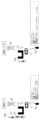
- FIG. 2 is a schematic diagram illustrating a control device according to an example of the disclosed subject matter. 2 is a flowchart illustrating an example of an initialization procedure of the control device illustrated in FIG. 1 .
- FIG. 2 is a diagram illustrating, in a simplified manner, a number of first, second and third obstacle parameters that may be determined by the control device illustrated in FIG. 1 .
- FIG. 2 is a diagram illustrating, in a simplified manner, a number of first, second and third obstacle parameters that may be determined by the control device illustrated in FIG. 1 .
- FIG. 2 is a schematic diagram illustrating an example of tracking an obstacle using a control device other than that illustrated in FIG. 1 .
- FIG. 2 is a schematic diagram illustrating an example of tracking an obstacle using the control device illustrated in FIG.
- FIG. 4 is a flow chart illustrating an example of how the control device illustrated in FIG. 1 recognizes that a first measuring unit has detected the same obstacle as a second measuring unit.
- 2 is a flow chart illustrating an example of enabling driving assistance by the control device illustrated in FIG. 1 .
- FIG. 2 is a schematic diagram illustrating an example of enabling driving assistance using a control device other than that illustrated in FIG. 1 .
- FIG. 2 shows a schematic diagram of an example of activating driving assistance using the control device shown in FIG. 1 .
- 9 is a flowchart illustrating an example of the control devices shown in FIG. 8 each receiving a specification of a plurality of second obstacle parameters and adjusting a confidence index of the second obstacle parameters based on the received specifications.
- 9 is a flow chart illustrating an example of the control devices shown in FIG. 8 each receiving a specification of a plurality of second obstacle parameters and adjusting a confidence index of the second obstacle parameters based on the received specifications.
- 9 is a flow chart illustrating an example of adjusting a reliability index based on a specification parameter by the control device illustrated in FIG. 8 , each of which is a flowchart illustrating an example of adjusting a reliability index based on a specification parameter by the control device illustrated in FIG. 9 is a flow chart illustrating an example of adjusting a reliability index based on a specification parameter by the control device illustrated in FIG.
- each of which is a flowchart illustrating an example of adjusting a reliability index based on a specification parameter by the control device illustrated in FIG. 9 is a flow chart illustrating an example of adjusting a reliability index based on another specification parameter by the control device illustrated in FIG. 8 , each of which is a flowchart illustrating an example of adjusting a reliability index based on another specification parameter by the control device illustrated in FIG. 9 is a flow chart illustrating an example of adjusting a reliability index based on another specification parameter by the control device illustrated in FIG. 8 , each of which is a flowchart illustrating an example of adjusting a reliability index based on another specification parameter by the control device illustrated in FIG.
- 9 is a flow chart illustrating an example of adjusting the reliability index based on further specification parameters by the control device illustrated in FIG. 8 .
- 9 is a flow chart illustrating an example of adjusting a confidence index based on map information by the control device illustrated in FIG. 8 .
- 9 is a flow chart illustrating an example of adjusting the reliability index based on further specification parameters by the control device illustrated in FIG. 8 .
- 9 is a flow chart illustrating an example of processing a plurality of second obstacle parameters, each received from more than one second measuring device, by the control device illustrated in FIG. 8 .
- 9 is a flow chart illustrating an example of processing a plurality of second obstacle parameters, each received from more than one second measuring device, by the control device illustrated in FIG. 8 .
- FIG. 9 is a flow chart illustrating an example of prioritizing multiple second obstacle parameters received from more than one second measuring device by the control device illustrated in FIG. 8 .
- 9 is a flow chart illustrating an example of recognizing a plurality of second obstacle parameters, each received from more than one second measuring device, by the control device illustrated in FIG. 8 .
- 9 is a flow chart illustrating an example of recognizing multiple second obstacle parameters, each received from more than one second measuring device, by the control device illustrated in FIG. 8 .
- 9 is a flow chart illustrating an example of recognizing multiple second obstacle parameters, each received from more than one second measuring device, by the control device illustrated in FIG. 8 .
- FIG. 9 shows a schematic diagram of an example of driving assistance using the control device shown in FIG.
- FIG. 9 shows a schematic diagram of an example of driving assistance using the control device shown in FIG. 8 when an obstacle is detected by a second measuring device.
- FIG. 9 shows a schematic diagram of an example of driving assistance using the control device shown in FIG. 8 when an obstacle is detected by more than one second measuring device.
- FIG. 9 shows a schematic diagram of an example of driving assistance using the control device shown in FIG. 8 when an obstacle is detected by more than one second measuring device.
- 9 is a flow chart illustrating an example of adjusting a confidence index based on different fields of view of more than one second measurement device by the control device illustrated in FIG. 8 .
- FIG. 9 is a flow chart illustrating an example of adjusting a confidence index based on different fields of view of more than one second measurement device by the control device illustrated in FIG. 8 .
- 9 is a flow chart illustrating an example of adjusting a confidence index based on different fields of view of more than one second measurement device by the control device illustrated in FIG. 8 .
- FIG. 13 is a schematic diagram of a control device according to yet another example of the disclosed subject matter.
- 22 is a flow chart illustrating an example of receiving specifications of a plurality of second obstacle parameters and adjusting a confidence index of the second obstacle parameters based on the received specifications by the control device illustrated in FIG. 21 .
- 22 is a flowchart illustrating an example of an initialization process of the control device illustrated in FIG. 21.
- FIG. 22 is a flowchart illustrating an example of an initialization process of the control device illustrated in FIG. 21. 22 is a flowchart illustrating an example of enabling driving assistance by the control device illustrated in FIG. 21. A diagram illustrating an example of driving assistance performed using a control device other than the one illustrated in FIG. 21 , in comparison with driving assistance performed using the control device illustrated in FIG. 21 . A diagram illustrating an example of driving assistance performed using a control device other than the one illustrated in FIG. 21 , in comparison with driving assistance performed using the control device illustrated in FIG. 21 .
- FIG. 25C is a schematic diagram illustrating the results of the driving assistance example illustrated in FIGS. 25a and 25b.
- FIG. 13 is a schematic diagram of a control device according to yet another example of the disclosed subject matter.
- FIG. 28 is a diagram illustrating an example of driving assistance when an obstacle is detected using the control device illustrated in FIG. 27 .
- FIG. 28 is a schematic diagram illustrating another example of driving assistance when an obstacle is detected using the control device illustrated in FIG. 27 .
- FIG. 28 is a schematic diagram illustrating another example of driving assistance when an obstacle is detected using the control device illustrated in FIG. 27 .
- FIG. 13 is a schematic diagram of a control device according to yet another example of the disclosed subject matter.
- 31 is a flow chart illustrating an example of a control process performed by the control device shown in FIG. 30.
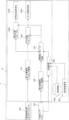
- FIG. 1 is a schematic diagram of a control device 1 according to an example of the disclosed subject matter.
- the control device 1 is mounted on a vehicle V, which is equipped with an on-board sensor (first measurement device) 100 for detecting obstacles around the vehicle V, and the first measurement device/on-board sensor 100 may include, for example, a radar sensor, a camera sensor, a lidar sensor, a sonar sensor, a GNSS sensor, and/or any other sensor suitable for detecting obstacles around the vehicle V.
- the control device 1 is communicatively connected to an external sensor (second measurement device) 102 that may be connected to the control device 1 via vehicle-to-location (V2X) communication.
- V2X vehicle-to-location
- the external sensor 102 may also be a radar sensor, a camera sensor, a lidar sensor, a sonar sensor, a GNSS sensor, and/or any other sensor suitable for detecting obstacles around the vehicle V, and the external sensor 102 may be included in, for example, another vehicle, a roadside unit, and/or a mobile device.
- the communication between the on-board sensor 100 and the control device 1 may be performed in real time, while the communication between the external sensor 102 and the control device 1 may be performed, for example, via a cellular network, which involves longer latency periods.
- Both the on-board sensor 100 and the external sensor 102 may detect obstacles in an area surrounding the vehicle V and may determine a number of first and second obstacle parameters including, for example, obstacle type, position, heading, speed, yaw rate, and acceleration of the detected obstacle.
- the plurality of first and second obstacle parameters may be divided into a first group including one or more parameters of a first category and a second group including one or more parameters of a second category.
- the categories of parameters may be defined, for example, by features/attributes/characteristics that one parameter may have in common with another parameter.
- the parameters of the first category may be obstacle position parameters including static information about the obstacle and the parameters of the second category may be obstacle movement parameters including dynamic information about the obstacle.
- Static information about an obstacle may be, for example, the type of obstacle (pedestrian, bicycle, vehicle, etc.), the current time (timestamp) at which the obstacle was detected, and its current location and heading.
- static information is characterized by facts that are time-independent with respect to the time of acquisition.
- dynamic information about an obstacle may be, for example, its speed, yaw rate, and acceleration.
- dynamic information is characterized by facts that are time-dependent with respect to the time of acquisition.
- the control device 1 comprises a first and a second obstacle (parameter) acquisition unit 101, 103 which may receive a plurality of first and second obstacle parameters from the on-board sensor 100 and the external sensor 102.
- the obstacle parameter acquisition unit 101, 103 may for example process (e.g. smooth, filter, average) the first and second obstacle parameters before being transmitted to the obstacle parameter calculation unit 104 of the control device 1 or may determine or select the parameters, especially if the first/second measuring device is mainly configured to detect objects.
- the obstacle parameter calculation unit 104 may also be possible for the obstacle parameter calculation unit 104 to directly receive the first and second obstacle parameters from the on-board sensor 100 and the external sensor 102.
- FIG. 1 shows a configuration in which the control device 1 is part of the vehicle V and the external sensor (second measuring device) 102 is located remotely to the vehicle V.
- both measuring devices 100 and 102 may be located external/remotely to the vehicle V.
- the example of FIG. 1 (or further control devices 1a-1d) may also be modified such that at least one of the sensors (first/second measuring device) may be combined with the respective obstacle parameter acquisition unit 101, 103.
- the first measuring device 100 and the first obstacle parameter acquisition unit 101 may be the same or an integrated unit (rather than separate units) and more preferably both of them may therefore be part of the control device 1.
- the second measuring device 102 may be located remotely to the vehicle V, whereby the second obstacle parameter acquisition unit 103 may be located as illustrated in FIG. 1.
- the obstacle parameter calculation unit 104 then calculates a third set of obstacle parameters based on the first and second obstacle parameters, which may include one or more position parameters and one or more movement parameters.
- the obstacle parameter calculation unit 104 uses the first and second obstacle parameters determined by the on-board sensors 100 and the external sensor 102 (or the obstacle parameter acquisition unit) to calculate a new set of third obstacle parameters.
- Position parameters such as the position and heading of the obstacle change their value each time they are determined by the first/second measuring device (sensor) 100, 102, and are therefore preferably sent immediately to the obstacle parameter calculation unit 104, so that the obstacle parameter calculation unit 104 can obtain the current value of the position parameters.
- movement parameters such as the speed, acceleration and yaw rate of the obstacle may be assumed to remain constant within the observed time slot. Therefore, the time of sending the movement parameters to the obstacle parameter calculation unit 104 may be less important than the sending of the position parameters.
- the accuracy and certainty of the determination of the obstacle parameters increases with each determination (step), i.e. the earlier certain obstacle parameters can be determined, the higher their accuracy and certainty.
- the obstacle parameters can also be determined by the obstacle parameter acquisition unit from the detected object data received from the sensors 100, 102.
- the sensors 100, 102 determine the parameters of the detected obstacles and transmit them, even if not explicitly stated, to a next unit such as the obstacle parameter calculation unit 104 of the control device 1, preferably via the first/second obstacle parameter units 101, 103.
- This also has further variants of the control device as shown in Figures 8, 21, etc.
- the obstacle parameter calculation unit 104 retrieves position parameters that can be determined with greater certainty by the on-board sensor 100 from the first plurality of obstacle parameters and movement parameters that can be determined with greater certainty by the external device 102 from the second plurality of obstacle parameters in order to calculate a new set of third obstacle parameters.
- the illustrated control device 1 further includes an enable unit 105 that calculates a first judgment parameter based on the plurality of third obstacle parameters received from the obstacle parameter calculation unit 104 and enables the driving assistance if the judgment parameter is smaller than a predetermined activation threshold.
- the obstacle parameter calculation unit 104 transmits the plurality of third obstacle parameters to the enable unit 105, which derives comparison data (judgment parameter) from the third obstacle parameters to determine whether to activate the driving assistance.
- the driving assistance may be, for example, automatic braking, acceleration, or steering. Alternatively or additionally, the driving assistance may also be an auditory or visual signal prompting the driver to perform a certain action.
- the enable unit 105 compares the judgment parameter with a predetermined activation threshold and enables the driving assistance if the judgment parameter is below the threshold. For example, the enable unit 105 may calculate the time until the vehicle reaches the obstacle (time to collision) or the difference between the vehicle and the obstacle as the judgment parameter based on the third obstacle parameter.
- the predetermined activation threshold in this case may be a predetermined time or a predetermined distance.
- control device 1 may further comprise an enabling unit 106 that may enable driving assistance based on an enable signal received from the enabling unit.
- the enabling unit 105 may send an enable signal to the enabling unit 106, which in turn enables actuators/control elements for driving assistance in the vehicle, such as hydraulic valves for braking or steering actuation and/or signal outputs for providing audible or visual information.
- actuators/control elements for driving assistance in the vehicle such as hydraulic valves for braking or steering actuation and/or signal outputs for providing audible or visual information.
- the actuators may also be possible for the actuators to be directly enabled by (the signal sent by) the enabling unit 105.
- the enabling unit 105 When the enabling unit 105 derives the first decision parameter from the third obstacle parameters, which are based on the most probable obstacle parameters derived from the on-board sensors 100 and the external sensors 102, the enabling unit 105 can determine the first decision parameter early with high accuracy. This allows the control device to activate the driving assistance before the obstacle appears next to the vehicle, thus avoiding abrupt driving movements and increasing driving comfort.
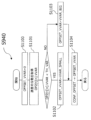
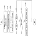
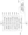
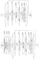
- FIG. 2 is a flow chart illustrating an example of an initialization procedure of the control device 1 illustrated in FIG. 1.
- FIG. 2 illustrates an initialization process of a prediction model included in the obstacle parameter calculation unit 104 of the control device 1 illustrated in FIG. 1.
- step S200 a number/set of previously calculated third obstacle parameters OP3[t-1][Q] are loaded by the obstacle parameter calculation unit 104, where the variable Q denotes the matrix of the third obstacle parameters and the variable t denotes time.
- the prediction model of the obstacle parameter calculation unit 104 calculates a current set of third obstacle parameters OP3p[t][Q] based on the third obstacle parameters OP3[t-1][Q] determined in the previous step. Then, in a step S202, the obstacle parameter calculation unit 104 receives a current set of first obstacle parameters OP1[t][M], where the variable M denotes the matrix of the first obstacle parameters.
- step S203 the obstacle parameter calculation unit 104 compares the obstacle positions from the current set of third obstacle parameters OP3p[t][Q] with the obstacle positions from the first set of obstacle parameters OP1[t][M].
- step S208 the predictive model of the obstacle parameter calculation unit 104 is updated using the calculated current set of third obstacle parameters OP3p[t][Q] and the position parameters OP1[t][m] of the first plurality of obstacle parameters.
- step S208 the confidence index OP3[t][q].CONF for the third obstacle parameters is incremented when the obstacle parameter calculation unit 104 receives a new set of first obstacle parameters from the on-board sensor 100.
- Each received set of first obstacle parameters from the on-board sensor 100 increases the certainty of the obstacle detection, and thus the confidence index OP3[t][q].CONF is incremented each time the obstacle parameter calculation unit 104 receives a new first obstacle parameter from the on-board sensor 100.
- step S209 a reliability flag OP3[t][q].TGFLG of the third obstacle parameters is set to 1, indicating that the plurality of third obstacle parameters can be used by the enable unit 105 to determine the time to collision TTC[Q] as a decision parameter (see FIG. 6).
- step S204 the obstacle parameter calculation unit 104 receives a plurality of second obstacle parameters OP2[t][N] determined by the external sensor 102, where the variable N denotes a matrix of the second obstacle parameters.
- step S205 since the communication between the external sensor 102 and the obstacle parameter calculation unit 104 involves delays, the predictive model of the obstacle parameter calculation unit 104 calculates a current set of second obstacle parameters OP2p[t][N] based on the determined second obstacle parameters OP2[t][N].
- step S206 the obstacle parameter calculation unit 104 compares the position of the obstacle from the current set of second obstacle parameters OP2p[t][N] with the position of the obstacle from the first set of obstacle parameters OP1[t][M].
- step S207 the prediction model of the obstacle parameter calculation unit 104 is initialized using the current movement parameter OP2p[t][n] of the second obstacle parameter OP2p[t][N] and the position parameter OP1[t][m] of the first obstacle parameter.
- step S209 the third obstacle parameter confidence flag OP3[t][q].TGFLG is set to 1, indicating that a plurality of third obstacle parameters are available for use by the enable unit 105 to determine the time to collision TTC[Q] as a decision parameter (see FIG. 6).
- the obstacle parameter calculation unit 104 considers the obstacle detected by the on-board sensor 100 to be a new or other obstacle in the first obstacle parameters. In this case, the described process is repeated until the external sensor 102 further detects a new obstacle in the second obstacle parameters.
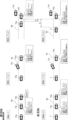
- Figures 3a and 3b are schematic diagrams illustrating examples of first, second and third obstacle parameters that may be determined by the control device illustrated in Figure 1.
- FIG. 3a illustrates a number of first obstacle parameters OP1[t][M] determined by a first measuring device, such as the on-board sensor 100 illustrated in FIG. 1.
- the number of first obstacle parameters OP1[t][M] includes the position of the obstacle detected by the first measuring device 100 in x- and y-coordinates PX1, PY1, as well as the heading direction TH1, the speed VX1, VY1 in the x- and y-directions, the yaw rate YAW1, and the acceleration AX1, AY1 in the x- and y-directions of the detected obstacle.
- the illustrated number of first obstacle parameters OP1[t][M] includes a confidence indicator CONF1 representing the certainty of the determined first obstacle parameters OP1[t][M] and the type/class CLS1 of the detected obstacle, where the class may indicate a type of vehicle or obstacle or another traffic participant, such as a car, a bicycle, a fixed obstacle, a pedestrian, etc.
- Figure 3a also shows a number of second obstacle parameters OP2[t][N] that include the same type of parameters as the number of first obstacle parameters OP1[t][M].
- the second obstacle parameters are determined by a second measuring device, such as the external sensor 102 shown in Figure 1, and are accordingly indicated by a "2".
- the first obstacle parameters are shown in normal font, while the second obstacle parameters are marked by bold symbols (letters, numbers, etc.). In this way, it is highlighted which of the third obstacle parameters are obtained from the first obstacle parameters and which are obtained from the second obstacle parameters to determine the initial values for the predictive model of the obstacle parameter calculation unit 104.
- FIG. 3a shows in bold the value of the third obstacle parameter if/when the value of the third obstacle parameter is derived from the value of the second obstacle parameter, and non-bold values of the third obstacle parameter are/are obtained from the value of the first obstacle parameter.
- the third obstacle parameters OP3[t][Q] are shown on the right side of Fig. 3a, where the position parameters timestamp TM1, position PX1, PY1 and heading TH1 are not marked in bold, i.e. they are obtained from the first obstacle parameters, and the movement parameters velocity VX2, VY2, yaw rate YAW2 and acceleration AX2, AY2 are marked in bold, i.e. they are obtained from the second obstacle parameters.
- the illustrated third obstacle parameter OP3[t][Q] further comprises a reliability index, preferably consisting of the reliability indexes CONF1 and CONF2 of the first and second obstacle parameters (here added, e.g. as indicated by "+"), and the same type/class of the detected vehicle as the first and second obstacle parameters CLS1 and CLS2.
- the third obstacle parameter comprises a reliability flag TGFLG, which is preferably set to 0 at the first time when the obstacle is detected by the first measuring device 100 and the second measuring device 102.
- the second obstacle parameters OP2[t][N] also include the width WD2 and height HT2 of the vehicle, which are carried over to the third obstacle parameters to initialize the predictive model of the obstacle parameter calculation unit 104.
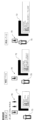
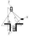
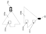
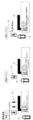
- FIG. 4a is a schematic diagram showing an example of tracking an obstacle using a control device other than the one shown in FIG. 1, and FIG. 4b is a schematic diagram showing an example of tracking an obstacle using the control device shown in FIG. 1.
- the obstacle tracking unit 400a is initialized using only the first obstacle parameter determined by the on-board sensor 100a. Furthermore, the obstacle tracking is also performed based only on the first obstacle parameter determined by the on-board sensor 100a. Depending on the number of times the obstacle parameter is determined by the on-board sensor 100a, the confidence in the determined parameter increases. If this confidence exceeds a predefined threshold, a change in the determined parameter from a low confidence (value) to a high confidence (value) is performed by the obstacle tracking unit 400a. After that, when the collision time to collision etc. can be calculated by the enable unit 105a, the driving assistance can be enabled by the enable unit 106a if the collision time to collision is less than the predefined threshold.
- the control device of FIG. 1 is used, and an additional external sensor 102 is applied in addition to the on-board sensor 100b, which may detect obstacles earlier than the on-board sensor 100b, but may have a longer communication path/slower communication speed to the obstacle tracking unit 400b.
- the obstacle tracking unit 400b which may include at least the obstacle parameter calculation unit 104 of the control device in FIG. 1, is initialized with position parameters obtained from a first obstacle parameter determined by the on-board sensor 100b and movement parameters obtained from a second obstacle parameter determined by the external sensor 102.
- the determined parameter reliability (value) will converge/increase faster than in the example shown in FIG. 4a.
- the time to crash can be calculated earlier by the enable unit 105b, resulting in earlier activation of the driving assistance by the enable unit 106b.
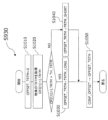
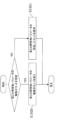
- FIG. 5 shows a flow chart of a subroutine of the control device of FIG. 1, illustrating an example of recognizing whether a first measurement unit has detected the same obstacle as a second measurement unit.
- the process as illustrated by the flow chart of FIG. 5 shows an example in which an assessment of whether the same obstacle has been detected is made by comparing the obstacle position of the first and second obstacle parameters according to step S206 of FIG. 2.
- the obstacle parameter calculation unit 104 first checks whether the first and second measuring devices detect obstacles of the same type/class (first decision step of FIG. 5), where the term CLS refers to the type/class of obstacle and the variables n and m indicate the second and first obstacle parameters, respectively. Then, in step S500, the obstacle parameter calculation unit 104 calculates the distance dis between the positions of the obstacles detected by the first and second measuring devices using the least squares method (sqrt: square root), where the terms PX and PY refer to the x- and y-coordinates of the obstacle positions.
- sqrt square root
- step S501 the detected obstacles are recognized as the same obstacle, and the process shown in the flowchart of FIG. 2 continues to step S206.
- step S502 two different obstacles are recognized and the process shown in the flowchart of FIG. 2 returns to step S204. This also applies if the obstacle parameter calculation unit 104 determined different types of obstacles at the beginning of the process (the "no" path from the first determination step in FIG. 5).
- FIG. 6 is a flow chart illustrating an example of enabling/activating driving assistance using the control device illustrated in FIG. 1.
- the enable flag AEB_FLG for driving assistance including automatic emergency braking (AEB) is set to 0, i.e., automatic emergency braking is disabled.
- the automatic emergency braking can be activated either by the time to collision TTC[m] calculated on the basis of the first obstacle parameter and/or by the time to collision TTC[q] calculated on the basis of the third obstacle parameter.
- the use of both sets of parameters, i.e. a plurality of first and third obstacle parameters ensures, on the one hand, that the automatic emergency braking is initialized also if the second measuring device is not available.
- the reliability of the AEB function is further increased while at the same time allowing for an improvement in driving comfort.
- FIG. 7a is a schematic diagram showing an example of enabling driving assistance using a control device other than the one shown in FIG. 1
- FIG. 7b is a schematic diagram showing an example of enabling driving assistance using the control device 1 shown in FIG. 1.
- FIG. 7a shows an example in which a driving assistance such as emergency braking is enabled only based on a plurality of first obstacle parameters
- FIG. 7b shows an example in which a driving assistance such as emergency braking is enabled based on a plurality of first and second obstacle parameters.
- a pedestrian 70, a boundary 72 (e.g., a wall of a building) and a vehicle 75 or V with an on-board sensor as a first measuring device are shown.
- the pedestrian 70 approaches in front of the vehicle 75 or V from the area behind the boundary 72 at time T.
- the vehicle's on-board sensors determine a first obstacle parameter OP1[T][m] at time T when the pedestrian 70 is first detected.
- the pedestrian's position initially determined by the on-board sensors is marked by a frame surrounding the pedestrian.
- the first obstacle parameters OP1[T][m] contain the x and y coordinates of this position PX1, PY1, but not the speed of the pedestrian 70, since at this point in time no previous position of the pedestrian is known, based on which the speed of the pedestrian can be determined by the on-board sensors of the vehicle 75.
- the confidence index CONF1 of the first obstacle parameters OP1[T][n] is therefore low at time T.
- the on-board sensors of the vehicle 75 determine the first obstacle parameter OP1[T+t1][n] at least once more (indicated by the length of the dotted arrow attached to the box surrounding the pedestrian 70), including the speed of the pedestrian 70 in the x- and y-directions VX, VY, which is now adversely affected by a coefficient ⁇ smaller than 1 indicating that the variance of the determined speed is still high due to the limited number of measurement points.
- the confidence index CONF1 of the first obstacle parameter OP1[T+t1][n] is increased at time T+t1 by the number of times ⁇ CONF that the on-board sensors of the vehicle 75 have determined the first obstacle parameter of the pedestrian 70.
- the vehicle's on-board sensors observe the pedestrian 70 for an extended period of time (indicated by the increased length of the dotted arrows attached to the frame surrounding the pedestrian 70), such that at this point in time the pedestrian's speeds VX1, VY1 can be determined with suitable accuracy. That is, the reliability index CONF1 of the first obstacle parameters exceeds the first predetermined reliability threshold TM_CONF, and the time to collision can be reliably calculated based on the first obstacle parameters OP1[T+t2][n] at time T+t2.
- FIG. 7b shows an example in which a number of first obstacle parameters are also determined by the on-board sensors 100 of the vehicle V, and in addition a number of second obstacle parameters are determined by an external sensor, such as the mobile device of the pedestrian 70.
- the external sensor can determine the second obstacle parameter of the pedestrian 70 before the on-board sensors of the vehicle first detect the pedestrian 70 at time T. This is shown by the dotted box surrounding the position of the pedestrian 70 when the pedestrian is still located in the area behind the boundary 72 where the pedestrian is not visible to the on-board sensors of the vehicle V.
- the position of the pedestrian 70 first detected by the on-board sensors is again marked by a solid line surrounding the pedestrian 70. At that time, the pedestrian has already been observed by the external sensor for a certain time, as indicated by the length of the dotted arrow attached to the solid box surrounding the pedestrian 70.
- the control device 1 has already calculated a number of third obstacle parameters OP3[T][q] at time T, which include the position PX1, PY1 of the pedestrian 70a determined by on-board sensors and the speed VX, VY of the pedestrian 70, for example determined by the pedestrian's mobile device.
- This speed is adversely affected by a coefficient ⁇ smaller than 1, which indicates that the variance of the determined speed is still high due to the limited number of measurement points.
- the reliability index takes into account the reliability CONF1, CONF2 of the first and second obstacle parameters and is therefore higher than the reliability index CONF1 at time T in FIG. 7a.
- the on-board sensor 100 determines the first obstacle parameter OP1[T+t1][n] at least once more, whereby the reliability index CONF1+CONF2 is increased by the number of times ⁇ CONF that the on-board device has determined the first obstacle parameter of the pedestrian 70.
- the value of the reliability index already exceeds the predefined threshold value TH_CONF at time T+t1.
- the time to collision can already be calculated with high certainty at time T+t1 based on the third obstacle parameter OP3[T+t1][n].
- the illustrated control device 1a includes a specification acquisition unit 802 that can receive specifications of a plurality of second obstacle parameters from an external sensor (second measuring device) 102 and/or a second obstacle parameter acquisition unit 103. Furthermore, a storage 800 in which map information regarding the surroundings of the vehicle V is stored and a signal strength acquisition unit 801 that can acquire the signal strength of wireless communication around the vehicle V are provided in the vehicle V (as shown). It is also possible that the specification acquisition unit 802, the map information storage 800, and the signal strength acquisition unit 801 are included in the obstacle parameter calculation unit 104 and thus in the control device 1a (not shown). Furthermore, alternatively, the storage 800 and the signal strength acquisition unit 801 can be located remotely with respect to the vehicle V (not shown).
- the obstacle parameter calculation unit 104 may calculate a reliability index that takes into account the specifications of multiple second obstacle parameters determined by the external sensor (second measurement device) 102. Because the external sensor 102 is located remotely with respect to the vehicle V, the influence of the method of detection and transmission of the second obstacle parameters may be stronger than in the case of the on-board sensor 100. For example, if the external sensor transmits a GNSS-based message, its accuracy may depend on the environment of the external sensor 102, since GNSS cannot provide a signal, for example, in a tunnel.
- the configuration/specification of the plurality of second obstacle parameters may include information (specification parameters) on the characteristics/properties/quality of the second obstacle parameters, including the characteristics/properties/quality of the external sensor 102.
- the specification may include, for example, information on the sensor type of the external sensor 102, the message type, the signal resolution, and the timestamp of the second measurement parameters, and/or any other transmission information on the characteristics/properties/quality of the plurality of second obstacle parameters.
- the specification acquisition unit 802 may receive the specifications of the plurality of second obstacle parameters from the external sensor 102 and/or the second obstacle parameter acquisition unit 103.
- the obstacle parameter calculation unit 104 may then adjust the value of the reliability index based on the plurality of specification parameters received from the specification acquisition unit 802.
- the specification acquisition unit 802 may receive from the map information storage 801 a number of map information pieces, including, for example, information about the location of buildings, etc., as well as traffic information, such as congestion, on which the obstacle parameter calculation unit 104 may further conclude the quality of the second obstacle parameter determined by the external sensor 102.
- the specification acquisition unit 802 may receive from the signal strength acquisition unit 801 the signal strength of the wireless communication around the vehicle on the basis of which the stability of the communication path between the external sensor 102 and the obstacle parameter calculation unit 104 and/or the specification acquisition unit 802 is determined.
- the obstacle parameter calculation unit 104 and/or the specification acquisition unit 802 may determine the stability of the communication path between the external sensor 102 and the obstacle parameter calculation unit 104 and/or the specification acquisition unit 802 from the information provided in the map information. For example, if the vehicle V is driving through an area with tall buildings, the stability/certainty/quality of the communication may be low since the buildings may obstruct the communication with the external sensor 102. The same is true if the vehicle is driving in a busy area where data traffic may be very high.
- These environmental conditions derivable from the map information can be used to determine the communication stability between the obstacle parameter calculation unit 104 and/or the specification acquisition unit 802 and the external sensor 102, and the obstacle parameter calculation unit 104 can increase or decrease the value of the reliability index based on the respective condition.
- FIGS. 9a and 9b are each a flowchart illustrating an example of receiving specifications for a plurality of second obstacle parameters and adjusting the reliability index of the second obstacle parameters based on the received specifications by the control device 1a illustrated in FIG. 8.
- Figure 9a illustrates multiple specification parameters received by the obstacle parameter calculation unit 104 and/or the specification acquisition unit 802 of the control device shown in Figure 8.
- the obstacle is another vehicle that has its own on-board measurement device and transmits cooperative awareness messages regarding its own status.
- the obstacle vehicle may also act as the second measurement device 102 transmitting the multiple specification parameters.
- the obstacle parameter calculation unit 104 and/or the specification acquisition unit 802 receive a timestamp indicating the latest second obstacle parameter determination of the other vehicle (S900), the tracking time (observation length) of the other vehicle including the number of times the second obstacle parameter was obtained (S901), the variance of the other vehicle's speed (S902), an AEB flag indicating whether the other vehicle's automatic emergency braking is enabled or not (S903), the message type of each second obstacle parameter (S904), and the communication stability between the other vehicle and the obstacle parameter calculation unit 104 and/or the specification acquisition unit 802 (S905).
- FIG. 9b illustrates the initialization of the prediction model of the obstacle parameter calculation unit 104 according to step S207 of FIG. 2, which is performed when the obstacle parameter calculation unit 104 and/or the specification acquisition unit 802 receives multiple specification parameters from other vehicles.
- step S910 the confidence offset CONF_OFFSET is set to 0 by the obstacle parameter calculation unit 104.
- the confidence offset CONF_OFFSET may vary depending on the specification parameters and may be added to the confidence index CONF2 of the second obstacle parameter.
- the confidence offset CONF_OFFSET is adjusted by the obstacle parameter calculation unit 104 based on each of the multiple specification parameters received from the other vehicle in steps S900 to S905 of FIG. 9a.
- step S980 the prediction model of the obstacle parameter calculation unit 104 is initialized taking into account the adjusted confidence offset CONF_OFFSET in the confidence index CONF2.
- the second measuring device may be a different obstacle or a different entity in general.
- FIGS. 10a and 10b are each a flowchart illustrating an example of adjusting a reliability index based on a specification parameter by the control device 1a illustrated in FIG. 8.
- the flow chart of FIG. 10a illustrates the adjustment of the confidence offset CONF_OFFSET based on the received timestamp indicating the latest second obstacle parameter determination of the other vehicle, which is performed in step S920 of FIG. 9b.
- the confidence offset due to the delay time OFFSET_DT is set to 0.
- the current time NOW_TM and the received timestamp OP2[t][n].TM indicating the latest second obstacle parameter determination of the other vehicle are determined.
- a delay time dt for transmitting the second obstacle parameter to the obstacle parameter calculation unit 104 is calculated in step S1004.
- the reliability offset due to the delay time OFFSET_DT is set to the value DELAY_BIG (S1005), and if the delay time dt is less than the predetermined delay time threshold TH_DT, the reliability offset due to the delay time OFFSET_DT is set to the value DELAY_SMALL (S1006).
- the reliability offset due to the delay time OFFSET_DT can be determined using a characteristic curve or a formula that depends on the delay time dt.
- step S1007 the confidence offset CONF_OFF is decreased by the value of the determined confidence offset due to the delay time OFFSET_DT.
- the confidence offset CONF_OFF is decreased by a smaller amount if the delay time dt is smaller than the predefined delay time threshold TH_DT and by a larger amount if the delay time dt is larger than the predefined delay time threshold TH_DT.
- the process of adjusting the confidence index based on the specification of the second obstacle parameter then proceeds to step S930 of FIG. 9b, which is shown in the flow chart illustrated in FIG. 10b.
- the flow chart of FIG. 10b illustrates the adjustment of the confidence offset CONF_OFFSET based on the received tracking time (observation length) of the other vehicle performed in step S930 of FIG. 9b.
- the confidence offset due to the tracking time OFFSET_TRTM of the other vehicle is set to 0.
- the tracking time OP2[t][n].TRTM is received from the other vehicle and is then compared to a predefined tracking time threshold TH_TRTM.
- the reliability offset due to the tracking time OFFSET_TRTM of the other vehicle is set to the value TRTM_LONG (S1030), and if the tracking time OP2[t][n].TRTM is less than the predetermined tracking time threshold TH_TRTM, the reliability offset due to the tracking time OFFSET_TRTM of the other vehicle is set to the value TRTM_SHORT (S1040).
- the confidence offset CONF_OFF is decreased by a smaller amount if the other vehicle's tracking time OP2[t][n].TRTM is greater than the predefined tracking time threshold TH_TRTM and is decreased by a larger amount if the other vehicle's tracking time OP2[t][n].TRTM is less than the predefined tracking time threshold TH_TRTM.
- the process of adjusting the confidence index based on the specification of the second obstacle parameter then proceeds to step S940 of FIG. 9b, which is shown in the flow chart illustrated in FIG. 11a.
- FIGS. 11a and 11b are each a flowchart illustrating an example of adjusting a reliability index based on another specification parameter by the control device 1a illustrated in FIG. 8.
- the flow chart of FIG. 11a illustrates the adjustment of the confidence offset CONF_OFFSET based on the received variance of the other vehicle's speed, performed in step S940 of FIG. 9b.
- the confidence offset due to the variance of the other vehicle's speed OFFSET_VVAR is set to 0.
- the variance of the other vehicle's speed OP2[t][n].VVAR is received from the other vehicle (or another entity acting as/having a second measurement device) and is then compared with a predefined variance threshold TH_VAR.
- the reliability offset due to the variance of the other vehicle's speed OFFSET_VVAR is set to the value VVAR_SMALL (S1102), and if the variance of the other vehicle's speed OP2[t][n].VVAR is greater than the predefined variance threshold TH_VAR, the reliability offset due to the variance of the other vehicle's speed OFFSET_VVAR is set to the value VVAR_BIG (S1103).
- step S1104 the confidence offset CONF_OFF is reduced by the value of the determined confidence offset due to the variance OFFSET_VVAR of the other vehicle's speed.
- VVAR_SMALL being smaller than the value VVAR_BIG
- the confidence offset CONF_OFF is reduced by a smaller amount if the other vehicle's speed OP2[t][n].VVAR is smaller than the predefined variance threshold TH_VAR and by a larger amount if the other vehicle's speed OP2[t][n].VVAR is larger than the predefined variance threshold TH_VAR.
- the process of adjusting the confidence index based on the specification of the second obstacle parameter then proceeds to step S950 of FIG. 9b, which is shown in the flow chart illustrated in FIG. 11b.
- step S1110 the confidence offset due to the setting of the other vehicle's AEB flag OFFSET_AEBFLG is set to 0.
- step S1120 the setting of the other vehicle's AEB flag is received.
- the confidence value CONF_OFFSET is not increased due to the setting of the other vehicle's AEB flag.
- the process of adjusting the confidence index based on the specification of the second obstacle parameter then proceeds to step S960 of FIG. 9b, which is shown in the flow chart illustrated in FIG. 12.
- FIG. 12 is a flowchart illustrating an example of adjusting the reliability index based on further specification parameters by the control device 1a illustrated in FIG. 8.
- the flow chart of FIG. 12 illustrates the adjustment of the confidence offset CONF_OFFSET based on the received message type of each second obstacle parameter performed in step S960 of FIG. 9b.
- the confidence offset due to the message type OFFSET_MSGTYPE of the second obstacle parameter is set to 0.
- the message type OP2[t][n].MSG.TYPE of the second obstacle parameter is received from another vehicle (or the like in other examples).
- the confidence offset due to the message type OFFSET_MSGTYPE of the second obstacle parameter is set to the value OS_DIRECT_FROM_CAR in step S1202.
- step S1203 the confidence offset due to the message type OFFSET_MSGTYPE of the second obstacle parameter is set to the value OS_DETECT_FROM_RSU.
- step S1204 the confidence offset due to the message type OFFSET_MSGTYPE of the second obstacle parameter is set to the value OS_DETECT_FROM_CAR.
- step S1205 the confidence offset due to the message type OFFSET_MSGTYPE of the second obstacle parameter is set to the value OS_DETECT_CELLULAR.
- the confidence offset CONF_OFFSET is increased in step S1207 by the value of the confidence offset due to the message type OFFSET_MSGTYPE of the second obstacle parameter.
- the confidence offset CONF_OFFSET may be increased by a maximum amount if the message type is a cooperative awareness message that provides direct information about other vehicles, and may be increased by a minimum amount if the message is received from another vehicle, a roadside unit, or a device other than a mobile device.
- FIG. 13 is a flow chart illustrating an example of adjusting the reliability index based on map information by the control device 1a illustrated in FIG. 8.
- FIG. 13 shows how the reliability offset due to the message type OFFSET_MSGTYPE of the second obstacle parameter can be modified depending on the environmental conditions of the vehicle determined from the map information stored in the map information storage 800.
- map information providing information on the presence of a tall building or closed environment such as a tunnel in the area surrounding the vehicle is received by the obstacle parameter calculation unit 104 and/or the specification acquisition unit 802.
- step S1301 information on whether the vehicle is traveling under congested road conditions is received as map information.
- a value of the confidence offset due to the message type OFFSET_MSGTYPE of the second obstacle parameter such as OS_DIRECT_FROM_CAR, OS_DETECT_FROM_RSS, OS_DETECT_FROM_CAR, OS_DETECT_CELLULAR and/or OS_DETECT_OTHERS, is selected for each message type of the table.
- FIG. 14 is a flowchart illustrating an example of adjusting the reliability index based on further specification parameters by the control device 1a illustrated in FIG. 8.
- the flow chart of FIG. 14 illustrates the adjustment of the confidence offset CONF_OFFSET based on the received communication stability between the other vehicle and the obstacle parameter calculation unit 104 and/or the specification acquisition unit 802, which is performed in step S970 of FIG. 9b.
- step S1400 map information is loaded from the map information storage 800 and delivered to the obstacle parameter calculation unit 104 and/or the specification acquisition unit 802.
- step S1401 the confidence offset OFFSET_COMST due to the communication stability between the other vehicle and the obstacle parameter calculation unit 104 and/or the specification acquisition unit 802 is set to 0.
- it is checked in the map information whether a tall building exists in the area surrounding the vehicle. If so, the value of the confidence offset OFFSET_COMST due to the communication stability is reduced by the value MINUS_BUILD in step S1402.
- step S1404 it is checked whether the vehicle V is traveling in a smooth communication area free of obstacles and/or interference from other devices. If so, the value of the reliability offset due to communication stability OFFSET_COMST is increased by the value PLUS_COMGOOD in step S1404.
- step S1405 the signal strength of the wireless communication around the vehicle is received in step S1405 and checked whether the signal strength is low. If the signal strength is low, the value of the reliability offset due to communication stability OFFSET_COMST is decreased by the value MINUS_INTBAD in step S1406. Finally, in step S1407, the reliability offset CONF_OFFSET is increased by the resulting value of the reliability offset due to communication stability OFFSET_COMST. The process of adjusting the reliability index based on the specification of the second obstacle parameter then proceeds to step S980 in FIG. 9b, where the prediction model of the obstacle parameter calculation unit 104 is initialized with the reliability offset CONF_OFFSET.
- 15a and 15b are flowcharts illustrating an example of processing multiple second obstacle parameters detected by more than one second measurement device by the control device 1a illustrated in FIG. 8.
- FIG. 15a illustrates the process performed in step S204 of the initialization procedure illustrated in FIG. 2 when multiple sets of second obstacle parameters OP2[t][N] are received from multiple second measurement devices.
- FIG. 15b illustrates how the multiple sets of second obstacle parameters are processed in step S1500 of FIG. 15a.
- the multiple sets of second obstacle parameters are received in step S1510.
- the priority of the multiple sets is determined.
- the set of second obstacle parameters having the highest priority is selected as the multiple second obstacle parameters.
- the process returns to step S205 of FIG. 2, where the current second obstacle parameters are calculated/predicted.
- FIG. 16 is a flowchart illustrating an example of prioritizing multiple second obstacle parameters detected by more than one second measurement device by the control device 1a illustrated in FIG. 8.
- FIG. 16 shows a preferred example of how the priority of the multiple sets of second obstacle parameters may be determined in step 1520 of FIG. 15b.
- map information is received from a map information storage. Based on the received map information, it is determined whether the vehicle V is traveling in a closed environment, such as a tunnel. If so, the vehicle's status is set to a value INSIDE, which represents a reduced reliability of wireless communications around the vehicle. If not, it is further determined whether the vehicle is traveling in a congested environment. If so, in step S1602, the vehicle's status is set to a value CROWDED, which also represents a reduced reliability of wireless communications around the vehicle.
- step S1603 the vehicle's status is set to a value NORMAL, which represents an average reliability of wireless communications around the vehicle.
- NORMAL represents an average reliability of wireless communications around the vehicle.
- step S1604 a message type for each second obstacle parameter is received, and then in step 1605, a priority for each set of second obstacle parameters is determined based on the situation value and the message type. In other words, the set of second obstacle parameters that provides the highest degree of certainty is the highest priority result.
- the process then returns to step S1530 of FIG. 15b, and the set of second obstacle parameters with the highest priority is selected as the plurality of second obstacle parameters to be used.
- 17a-17c are flow charts illustrating another example of processing multiple obstacle parameters, each detected by more than one second measuring device, by the control device 1a illustrated in FIG. 8.
- FIG. 17a shows steps S1700-S1702 which are equivalent to steps S1510-S1530 of FIG. 15b.
- FIG. 17a includes a further step S1703 in which the confidence measure OP2[t][N].CONF of the second obstacle parameters is adjusted based on one or more sets of second obstacle parameters.
- step S1703 The process for adjusting the confidence index OP2[t][N].CONF in step S1703 is shown in FIG. 17b.
- the confidence index CONF_A is initially set to 0. Then, it is checked whether one set of second obstacle parameters OP2[t][n] and another set OP2_s[t][ns] have been received, and the variables n and ns indicate one and the other second obstacle parameters, respectively.
- step S1711 the two sets of second obstacle parameters are compared in step S1711 to determine whether two different second measuring devices 102 have detected the same obstacle. If the result is positive, the confidence index CONF_A is increased by the value of the confidence index of the other set of second obstacle parameters OP2_s[t][n].CONF. If the result is negative, the confidence index CONF_A remains at 0.
- step 1713 the reliability index OP2[t][n].CONF of one set of second obstacle parameters is increased by the reliability index value CONF_A, whereby, if both second measuring devices 102 detect the same obstacle, the reliability index OP2[t][n].CONF of one set of second obstacle parameters is increased.
- step S17c shows the process of determining whether both second measuring devices 102 have detected the same obstacle, performed in step S1711 of FIG. 17b.
- CLS refers to the type/class of the obstacle. If an obstacle of the same type/class is detected, in step S1720, the distance dis between the positions of the obstacles detected by one and the other second measuring device is calculated using the least squares method (sqrt: square root), where the terms PX and PY refer to the x and y coordinates of the obstacle's position.
- step S1721 the detected obstacles are recognized as the same obstacle and the process shown in the flowchart of FIG. 17b continues in step S1712, where the confidence index CONF_A is increased by the confidence index value OP_s[t][n].CONF of the other set of second obstacle parameters.
- step S1722 two different obstacles are recognized and the confidence index CONF_A remains 0.
- the confidence index CONF_A also remains 0 if different types of obstacles were determined in one and the other set of second obstacle parameters at the beginning of the process.
- 18a and 18b are each a flowchart illustrating an example of adjusting a confidence index based on different fields of view of one or more second measurement devices by the control device 1a illustrated in FIG. 8.
- steps S1800-S1802 and step S1804 are identical to steps S1710-S1713 of FIG. 17b.
- FIG. 18a includes step S1803 in which the confidence index CONF_A is adjusted based on the field of view of the other second measuring device. Next, the process of adjusting the confidence index CONF_A is described in FIG. 18b.
- the field of view FOV of the other second measuring device which determines the other set of second obstacle parameters OP_s[t][Ns] is received in step S1810, where the term Ns denotes the matrix of the other second obstacle parameters.
- Ns denotes the matrix of the other second obstacle parameters.
- the confidence index CONF_A remains unchanged and the process returns to step S1804 of FIG. 18a. Otherwise, it is checked whether the determined obstacle is recognized in the field of view of one of the second measuring devices 102. If not, the determined obstacle is not recognized in the field of view of either of the two second measuring devices, therefore the confidence index CONF_A remains unchanged and the process returns to step S1804 of FIG. 18a.
- FIG. 19a and 19b are schematic diagrams illustrating an example of a driving assistance usage scenario when an obstacle is detected by the second measuring device 102 using the control device 1a illustrated in FIG. 8.
- FIG. 19a shows a vehicle 75a traveling between two boundaries 72 (e.g., a building, etc.) such that a pedestrian 70 walking behind one of the boundaries 72 is not detectable by the on-board sensor 100 of the vehicle V (here 75a).
- the pedestrian 70 is recognized in the field of view of the on-board sensor of another vehicle 75b, e.g., another vehicle 75b traveling in a different direction and/or position.
- FIG. 19b shows the field of view 190 of the on-board sensor of the other vehicle 75b and the detection result 191 obtained by that on-board sensor. Comparing FIG. 19a and FIG. 19b, it can be seen that the position of the pedestrian 70 is correctly captured by the detection result 191 of the on-board sensor of the other vehicle 75b, but the vehicle 75a cannot "see” the pedestrian 70 using its on-board sensor, such as a stereo camera.
- 20a to 20c are schematic diagrams illustrating an example in which an obstacle is detected by more than one second measuring device 102 using the control device 1a illustrated in FIG. 8.
- Fig. 20a shows a vehicle V (here 75a), a pedestrian 70, a boundary 72, and another vehicle 75b, as already shown in Fig. 19a.
- Fig. 20a shows a roadside unit 80 (e.g., a traffic camera, etc.) with a field of view that is (for example) perpendicular to the field of view of the on-board sensor of the other vehicle 75b.
- a roadside unit 80 e.g., a traffic camera, etc.
- Figure 20b shows the field of view 190a of the on-board sensor of the other vehicle 75b, together with the detection result 191a as already shown in Figure 19b.
- Figure 20b shows the field of view 190b of the roadside unit 80. Based on the field of view 190b of the roadside unit, two different detection results 191b, 191f are captured. Comparing Figures 20a and 20b, it can be seen that the position of the pedestrian 70 is correctly captured by the detection result 191b and incorrectly captured by the detection result 191f.
- FIG. 20c shows the results when considering the fields of view 190a, 190b of two second measuring devices 102, namely the on-board sensor of the other vehicle 75b and the roadside unit 80.
- the position of the pedestrian may be correctly detected by both second measuring devices and the reliability index may increase.
- the detection result 190f of the roadside unit and the detection result 190a of the on-board sensor are taken into account, a discrepancy may arise between the two second measuring devices 75b, 80 and the reliability index may have to be decreased.
- FIG. 21 is a schematic diagram of a control device 1b according to another example of the disclosed subject matter.
- the control device of FIG. 21 includes an intervention enable unit 105a and a warning enable unit 105b instead of a single enable unit, and an associated intervention enable unit 106a and a warning enable unit 106b instead of a single enable unit, respectively.
- the warning enable unit 105b may calculate a warning determination parameter based on a plurality of third obstacle parameters that may cause a warning enablement by the warning enablement unit 106b when it falls below a predetermined warning enablement threshold.
- the intervention enable unit 105a may calculate an intervention determination parameter based on a plurality of third obstacle parameters that may cause an intervention enablement by the intervention enablement unit 106b when it falls below a predetermined intervention enablement threshold.
- the predetermined warning enablement threshold may be greater than the predetermined intervention enablement threshold.
- the warning and/or intervention determination parameter is a crash margin time
- the warning enablement threshold may include a crash margin time value greater than the intervention enablement threshold. Thereby, the warning may be enabled earlier than the intervention.
- the storage 800 and/or the signal strength acquisition unit 801 are part of the control device 1b, or they may be located remotely/outside the vehicle V.
- FIG. 22 is a flow chart illustrating an example of receiving specifications for a plurality of second obstacle parameters and adjusting, by the control device illustrated in FIG. 21, a reliability index for the second obstacle parameters based on the received specifications.
- Figure 22 illustrates the initialization of the predictive model of the obstacle parameter calculation unit 104 using a confidence offset CONF_OFFSET when the obstacle parameter calculation unit 104 and/or the specification acquisition unit 802 receive a number of specification parameters from a second measurement device 102, which may be (or may be included in) another vehicle (which parameters may also be received in the obstacle parameter calculation unit 104 from the respective obstacle parameter acquisition unit described above and illustrated in Figure 8 or Figure 21).
- the specification parameters based on which the confidence offset CONF_OFFSET is adjusted according to Figure 22 are the same as those shown in Figures 9a and 9b.
- steps S2200-S2207 in Fig. 22 are identical to steps S910-S970 in Fig.
- the obstacle parameter calculation unit 104 checks whether the confidence index OP3[t],[q].CONF of the third obstacle parameter is greater than a second predefined threshold TH_SEPARATE after the initialization in step S2207.
- two separate sets of third obstacle parameter units are initialized in step S2209, where the third obstacle parameter OP3W[t][q] used to calculate the warning decision parameter is based on the first and second obstacle parameters, and the third obstacle parameter OP3I[t][q] used to calculate the intervention decision parameter is based only on the first obstacle parameter.
- a warning (or its activation) may be enabled/triggered based on a combination of a position parameter obtained from the plurality of first obstacle parameters and a movement parameter obtained from the plurality of second obstacle parameters.
- interventions in the driver's driving behavior may be performed based only on the first obstacle parameters, which may preferably be determined by the vehicle's on-board measuring device. This ensures that the entire control of the driving assistance system may remain with the vehicle in cases where the external measuring device may have unknown certainty or a certainty below a predefined threshold.
- FIG. 23a is a flow chart illustrating an example of an initialization process of the control device illustrated in FIG. 21.
- FIG. 23a illustrates an initialization process of a prediction model included in the obstacle parameter calculation unit 104 of the control device illustrated in FIG. 21 regarding the calculation result of the third obstacle parameter OP3W[t][q] used to calculate the warning determination parameter.
- step S2300 of FIG. 23a a number/set of previously calculated third obstacle parameters OP3W[t-1][Q] are loaded by the obstacle parameter calculation unit 104, where the variable Q denotes the matrix of the third obstacle parameters and the variable t denotes time.
- the prediction model of the obstacle parameter calculation unit 104 calculates a current set of third obstacle parameters OP3Wp[t][Q] based on the third obstacle parameters OP3W[t-1][Q] determined in the previous step. Then, in a step S2302, the obstacle parameter calculation unit 104 receives a current set of first obstacle parameters OP1[t][M], where the variable M denotes the matrix of the first obstacle parameters.
- step S2303 the obstacle parameter calculation unit 104 compares the obstacle positions from the current set of third obstacle parameters OP3Wp[t][Q] with the obstacle positions from the first set of obstacle parameters OP1[t][M].
- step S2308 the predictive model of the obstacle parameter calculation unit 104 is updated using the calculated current set of third obstacle parameters OP3Wp[t][Q] and the position parameters OP1[t][m] of the first obstacle parameters.
- step S2308 when the obstacle parameter calculation unit 104 receives a new set of first obstacle parameters from the on-board sensor 100, the confidence index OP3W[t][q].CONF of the third obstacle parameters is incremented (not shown).
- Each received set of first obstacle parameters from the on-board sensor 100 increases the certainty of the obstacle detection, and thus the confidence index OP3W[t][q].CONF is incremented each time the obstacle parameter calculation unit 104 receives a new first obstacle parameter from the on-board sensor 100.
- step S2309 the reliability flag OP3W[t][q].TGFLG of the third obstacle parameters is set to 1, indicating that the plurality of third obstacle parameters are available for use by the enable unit 105 as warning decision parameters (see FIG. 24) to determine the time to collision TTC[Q].
- step S2304 the obstacle parameter calculation unit 104 receives a plurality of second obstacle parameters OP2[t][N] determined by the external sensor 102, where the variable N denotes a matrix of the second obstacle parameters.
- the predictive model of the obstacle parameter calculation unit 104 calculates a current set of second obstacle parameters OP2p[t][N] based on the determined second obstacle parameters OP2[t][N].
- step S2306 the obstacle parameter calculation unit 104 compares the position of the obstacle from the current set of second obstacle parameters OP2p[t][N] with the position of the obstacle from the first set of obstacle parameters OP1[t][M].
- step S2307 the prediction model of the obstacle parameter calculation unit 104 is initialized using the current movement parameter OP2p[t][n] of the second obstacle parameter OP2p[t][N] and the position parameter OP1[t][m] of the first obstacle parameter.
- step S2309 the third obstacle parameter confidence flag OP3W[t][q].TGFLG is set to 1 to indicate that a plurality of third obstacle parameters are available for use by the warning enable unit 105b as decision parameters (see FIG. 24) for determining the Time to Collision TTC[Q].
- FIG. 23b shows the initialization process of the predictive model included in the obstacle parameter calculation unit 104 of the control device 1b shown in FIG. 21 regarding the calculation result of the third obstacle parameter OP3I[t][q] used to calculate the intervention decision parameter.
- step S2310 a number/set of previously calculated third obstacle parameters OP3I[t-1][Q] are loaded by the obstacle parameter calculation unit 104, where the variable Q denotes the matrix of the third obstacle parameters and the variable t denotes time.
- the predictive model of the obstacle parameter calculation unit 104 calculates a current set of third obstacle parameters OP3Ip[t][Q] based on the third obstacle parameters OP3I[t-1][Q] determined in the previous step. Then, in step S2312, the obstacle parameter calculation unit 104 receives a current set of first obstacle parameters OP1[t][M], where the variable M denotes the matrix of the first obstacle parameters.
- step S2313 the obstacle parameter calculation unit 104 compares the obstacle positions from the current set of third obstacle parameters OP3Ip[t][Q] with the obstacle positions from the first set of obstacle parameters OP1[t][M].
- step S2318 the predictive model of the obstacle parameter calculation unit 104 is updated using the calculated current set of third obstacle parameters OP3Ip[t][Q] and the position parameters OP1[t][m] of the first obstacle parameters.
- step S208 when the obstacle parameter calculation unit 104 receives a new set of first obstacle parameters from the on-board sensor 100, the confidence index OP3I[t][q].CONF of the third obstacle parameters is incremented (not shown).
- Each received set of first obstacle parameters from the on-board sensor 100 increases the certainty of the obstacle detection, and thus the confidence index OP3I[t][q].CONF is incremented each time the obstacle parameter calculation unit 104 receives a new first obstacle parameter from the on-board sensor 100.
- step S2319 the reliability flag OP3I[t][q].TGFLG of the third obstacle parameters is set to 1, indicating that the plurality of third obstacle parameters can be used by the enable unit 105 to determine the time to collision TTC[Q] as a decision parameter (see FIG. 24).
- step S2314 the obstacle parameter calculation unit 104 receives a plurality of second obstacle parameters OP2[t][N] determined by the external sensor 102, where the variable N denotes a matrix of the second obstacle parameters.
- the predictive model of the obstacle parameter calculation unit 104 calculates a current set of second obstacle parameters OP2p[t][N] based on the determined second obstacle parameters OP2[t][N].
- step S206 the obstacle parameter calculation unit 104 compares the position of the obstacle from the current set of second obstacle parameters OP2p[t][N] with the position of the obstacle from the first set of obstacle parameters OP1[t][M].
- step S2317 the prediction model of the obstacle parameter calculation unit 104 is initialized using the current movement parameter OP2p[t][n] of the second obstacle parameter OP2p[t][N] and the position parameter OP1[t][m] of the first obstacle parameter.
- step S2319 the third obstacle parameter confidence flag OP3I[t][q].TGFLG is set to 1 to indicate that a plurality of third obstacle parameters are available for use by the enable unit 105 to determine the time to collision TTC[Q] as intervention decision parameters (see FIG. 24).
- FIG. 24 is a flowchart illustrating an example of enabling warnings and/or interventions as driving assistance by the control device 1b illustrated in FIG. 21.
- the warning enable flag WARN_FLG and the automatic emergency braking (AEB) enable flag AEB_FLG are set to 0 in steps S2400 and S2401, which means that the warning devices and the automatic emergency braking are disabled.
- step S2403 the warning enable unit 105a activates the warning by setting the activation flag WARN_FLG to 1.
- the intervention enable unit 105b checks whether the time to collision TTC [m] is less than a predetermined intervention enable threshold TH_TTC_I. If it is less than the threshold, the automatic emergency braking enable flag AEB_FLG is set to 1 in step S2404 to enable the automatic emergency braking.
- step S2408 the intervention enable unit 105b activates the automatic emergency brake by setting the activation flag AEB_FLG to 1.
- step S2400 If any of the checks performed in the second calculation loop are negative, the process returns to step S2400 and proceeds further until the warning flag WARN_FLG and/or the automatic emergency braking enable flag AEB_FLG are set to 1.
- the warning as well as the automatic emergency braking can be activated either by the time to collision TTC[m] calculated based on the first obstacle parameter and/or by the time to collision TTC[q] calculated based on the third obstacle parameter.
- the use of both sets of parameters, i.e. a plurality of first and third obstacle parameters, on the one hand ensures that the warning and the automatic emergency braking are initialized also if the second measuring device is not available.
- the use of the third obstacle parameter to calculate the time to collision ensures an early activation of the warning or the automatic emergency braking in case the second measuring device is available.
- FIG. 25a is a diagram that shows an example of driving assistance performed using a control device other than the one shown in FIG. 21, and FIG. 25b is a diagram that shows an example of driving assistance performed using the control device 1b shown in FIG. 21.
- FIG. 25a illustrates an example in which warning and emergency braking (AEB) are subsequently performed based only on a first plurality of obstacle parameters determined by the vehicle's on-board sensors
- FIG. 25b illustrates an example in which warning and emergency braking are subsequently performed based on a first and second plurality of obstacle parameters.
- AEB warning and emergency braking
- a pedestrian 70, a boundary 72 (e.g. a wall or a building) and a vehicle 75 (V is used in Fig. 25b) with an on-board sensor 100 as a first measuring device are shown.
- the pedestrian 70 approaches in front of the vehicle 75 from the area behind the boundary 72 at time T.
- the vehicle's on-board sensors determine a first obstacle parameter OP1[T][m] at time T when the pedestrian 70 is detected for the first time.
- the pedestrian's position as initially determined by the on-board sensors is marked by a box surrounding the pedestrian.
- the first obstacle parameter OP1[T][m] includes the x and y coordinates of this position PX1, PY1, but not the speed of the pedestrian 70, since at this point in time no previous position of the pedestrian is known, based on which the speed of the pedestrian can be determined by the on-board sensors of the vehicle 75.
- the confidence index at time T in FIG. 25a includes the confidence CONF1 of the first obstacle parameter at the current time and an offset that may depend, for example, on environmental conditions that affect the reliability of the received message.
- the on-board sensors of the vehicle 75 have determined the first obstacle parameters OP1[T+t1][n] at least once more (indicated by the length of the dotted arrow attached to the frame surrounding the pedestrian 70), including the speed of the pedestrian 70 in the x- and y-directions VX, VY, which is now adversely affected by a coefficient ⁇ smaller than 1 indicating that the variance of the determined speeds is still high due to the limited number of measurement points.
- the confidence index CONF1 of the first obstacle parameters OP1[T+t1][n] has been increased at time T+t1 by the number of times ⁇ CONF that the on-board sensors of the vehicle 75 have determined the first obstacle parameters of the pedestrian 70.
- the warning decision parameters can be determined with sufficient certainty based on the first obstacle parameters present at time T+t1 and the warning can be enabled by the warning enable unit 105a.
- the on-board sensors of the vehicle 75 observe the pedestrian 70 for a longer period of time (indicated by the increased length of the dotted arrows attached to the frame surrounding the pedestrian 70), such that at this point in time the speeds VX1, VY1 of the pedestrian 70 can be determined with suitable accuracy.
- the reliability index CONF1 of the first obstacle parameters exceeds a predefined intervention reliability threshold TM_CONF_1, such that an intervention decision parameter can be calculated with a high degree of certainty based on the first obstacle parameters OP1[T+t2][n] at time T+t2, and automatic emergency braking can be enabled by the intervention enable unit 105b.
- FIG. 25b illustrates an example in which a warning and automatic emergency braking (AEB) are subsequently performed based on a plurality of first and second obstacle parameters.
- AEB warning and automatic emergency braking
- FIG. 25b illustrates an example in which a plurality of first obstacle parameters are also determined by the on-board devices/sensors 100 of the vehicle V, and in addition, a plurality of second obstacle parameters are determined by an external sensor 102, such as a mobile device of the pedestrian 70.
- the external sensor can determine the second obstacle parameter of the pedestrian 70 before the on-board sensors of the vehicle V first detect the pedestrian 70 at time T. This is indicated by the dotted frame surrounding the position of the pedestrian 70 when the pedestrian 70 is still located in the area behind the boundary 72 that is not visible to the on-board sensors of the vehicle 75.
- the position of the pedestrian 70 first detected by the on-board sensors is again marked by a solid line surrounding the pedestrian 70.
- the pedestrian is observed by the external sensor for a specific period of time, indicated by the length of the dotted arrow attached to the solid frame surrounding the pedestrian 70.
- the obstacle parameter calculation unit 104 of the control device 1b illustrated in FIG. 21 determines a first plurality of third obstacle parameters for determining a warning decision parameter and a second plurality of third obstacle parameters for determining an intervention decision parameter.
- the first plurality of third obstacle parameters is based on the first and second obstacle parameters, while the second plurality of third obstacle parameters is based only on the first obstacle parameters.
- the first plurality of third obstacle parameters OP3W[T][q] includes the position PX1, PY1 of the pedestrian 70 determined by the on-board sensors and the velocity VX, VY of the pedestrian 70 determined by the external sensors.
- This velocity is adversely affected by a coefficient ⁇ smaller than 1 indicating that the variance of the determined velocity is still high due to the limited number of measurement points.
- the confidence index at time T in FIG. 25b includes the confidences CONF1, CONF2 of the first and second obstacle parameters at the current time and an offset and is therefore higher than the confidence index in FIG. 25a.
- the second plurality of third obstacle parameters OP3I[T][q] only includes the position PX1, PY1 of the pedestrian 70 determined by the on-board sensors. As these third obstacle parameters are based only on the first obstacle parameters, the speed of the pedestrian cannot be provided at time T. However, the reliability index of the second plurality of third obstacle parameters is identical to that of the first plurality of third parameters OP3W[T][q] when the second obstacle parameters are available in both cases. This is why the reliability of the second plurality of third obstacle parameters OP3I[T][q] also increases faster than the reliability of the first obstacle parameters.
- the first obstacle parameter has been determined at least once more, and thus the reliability index of the first and second plurality of third obstacle parameters OP3W[T+t1'][q] and OP3i[T+t1'][q] has been increased by the number of times ⁇ CONF that the on-board sensors of the vehicle V determined the first obstacle parameter of the pedestrian 70 at time T+t1'.
- the variance of the speeds VX, VY contained in the first plurality of third obstacle parameters OP3W[T+t1'][q] is reduced due to the increased observation time. The speeds are still adversely affected by the coefficient ⁇ , but may be higher than the coefficient ⁇ .
- the second plurality of third obstacle parameters is now calculated based on the first obstacle parameters determined by the on-board sensors of the vehicle V and includes speeds adversely affected by a coefficient ⁇ that is smaller than the coefficient ⁇ .
- the reliability index of the first plurality of third obstacle parameters exceeds the predetermined warning reliability threshold TH_CONF_W at time T+t1', and therefore the warning decision parameter can be determined with sufficient certainty based on the first plurality of third obstacle parameters OP3W[T+t1'][q] present at time T+t1', and the warning can be enabled by the warning enable unit 105a.
- Time t1' is less than time t1, i.e., in this case, the warning enable unit 105a can enable the warning earlier than in the case shown in FIG. 25a, and only the first obstacle parameter is used as the basis for determining the warning decision parameter.
- the reliability index of the second plurality of third obstacle parameters exceeds the intervention reliability threshold TH_CONF_I, and therefore the intervention decision parameter can be determined with sufficient certainty based on the second plurality of third obstacle parameters OP3I[T+T2'][q] present at time T+t2', and automatic emergency braking can be enabled by the intervention enable unit 105b.
- Figure 26 shows the results of the driving assistance example of Figures 25a and 25b diagrammatically in the form of a timeline t marked with time points of interest T, T+t1, T+t1', T+t2, T+t2' from a first observation at time T to activation of automatic emergency braking at times T+t2, T+t2'.
- time points for the example where only on-board sensors were used are shown above the timeline, and time points for the example where on-board and external sensors were used are shown below the timeline.
- on-board sensor 100 and external sensor 102 allows for earlier triggering of automatic emergency braking (AEB) as well as earlier triggering of warnings compared to using only on-board sensor 100.
- AEB automatic emergency braking
- This is also applicable to parameter determination for automatic emergency braking where the parameters of external sensor 102 are not used at all. However, these parameters are available to enable warnings, thus also increasing the certainty of the parameters used for emergency braking.
- FIG. 27 is a schematic diagram of a control device 1c according to another example of the disclosed subject matter.
- the control device of FIG. 27 differs from the control device illustrated in FIG. 1 in that the first and second measuring devices are external sensors 102a, 102b, i.e., both sensors are located outside the vehicle V.
- the external sensor 102a, 102b located closer to the vehicle V may serve as the first measuring device
- the external sensor 102a, 102b located further from the vehicle V may serve as the second measuring device.
- the external sensor 102a, 102b closer to the vehicle has a shorter latency period than the external sensor 102a, 102b located farther away.
- the external sensor 102a, 102b located farther away from the vehicle can detect an obstacle earlier than the external sensor 102a, 102b located closer to the vehicle. It will be further seen that two external sensors 102a, 102b provide their data to respective first/second obstacle parameter acquisition units 101, 103 within the control device 1c.
- a roadside unit e.g., a camera immediately to the right of the vehicle may act as a first measuring device, and if a pedestrian with a smartphone appears as an obstacle around the vehicle, the pedestrian's smartphone may act as a second measuring device.
- the control device 1c may receive signals from each of the external sensors 102a, 102b and determine which of the external sensors 102a, 102b should act as the first and second measuring devices, e.g., depending on the signal strength.
- the obstacle parameter calculation unit 104 may then receive the first and second obstacle parameters from both external sensors 102a, 102b (preferably via the first/second obstacle parameter acquisition units 101, 103 as described above) and calculate a third obstacle parameter based on the most certain parameter.
- FIG. 28 is a schematic diagram of an example of driving assistance when an obstacle is detected using the control device 1c illustrated in FIG. 27.
- FIG. 28 shows a vehicle V, a roadside unit 80, a boundary 72 (wall, building, etc.), a pedestrian 70a, and a cellular base station 85.
- the pedestrian 70a carries a mobile device (indicated by the two lightning bolt icons illustrated between the cellular base station 85 and the pedestrian) that transmits and receives GNSS-based messages over a cellular network provided by the cellular base station 85.
- This cellular network also reaches the vehicle V (indicated by the lightning bolt icon between the cellular base station 85 and the vehicle V), thereby enabling the mobile device of the pedestrian 70a to exchange messages with the vehicle V.
- the pedestrian 70a approaches the vicinity of the vehicle V from the area behind the boundary 72, which is outside the field of view of the vehicle V.
- the vehicle V is moving backwards, which causes the field of view 190a of its on-board sensor to be in the wrong direction, thereby making it unable to be used as a first measuring device.
- the roadside unit 80 is positioned next to the vehicle V, which ensures fast communication with the control device 1c, which may be located on the vehicle V (indicated by two lightning bolt icons between the roadside unit 80 and the vehicle V). Furthermore, the roadside unit can detect obstacles around the vehicle V due to its field of view 190b capturing the entire area surrounding the vehicle.
- the roadside unit may act as a first measuring device providing the position parameters of the pedestrian 70a, while the pedestrian's mobile device may act as a second measuring device providing the movement parameters of the pedestrian 70a.
- the third obstacle parameter of the pedestrian 70a can be calculated with high certainty by the obstacle parameter calculation unit 104 of the control device based on the plurality of first obstacle parameters received from the roadside unit 80 and the plurality of second obstacle parameters received from the pedestrian's mobile device.
- 29a and 29b are schematic diagrams illustrating an example of a driving assistance performed using a control device other than the one illustrated in FIG. 27, compared with an example of a driving assistance performed using the control device 1c illustrated in FIG. 27. Both figures show the situation already illustrated in FIG. 28, where the vehicle 75/V is moving backwards and a pedestrian 70, 70a is approaching the rear of the vehicle 75/V from the area behind the boundary 72.
- FIG. 29a shows an example where only the first obstacle parameters are determined by the roadside unit 80 and the mobile device of the pedestrian 70 is not used as a second measurement device (indicated by the absence of a lightning icon between the cellular base station 85 and the pedestrian 70).
- the roadside unit 80 first recognizes the pedestrian 70 and determines the position PX1, PY1 of the pedestrian.
- the position where the roadside unit 80 first detects the pedestrian 70 is marked by a box surrounding the pedestrian 70.
- the speed of the pedestrian 70 is determined by the roadside unit 80 to be 0 at time T, since the previous position of the pedestrian 70 is not known at that time, based on which the speed of the pedestrian can be determined. Therefore, the confidence index CONF1 of the first obstacle parameters OP1[T][n] is low at time T.
- the roadside unit 80 has determined the first obstacle parameter OP1[T+t1][n] at least once more, which now includes the speed of the pedestrian 70 in the x- and y-directions VX, VY being adversely affected by a coefficient ⁇ indicating that the speeds VX, VY have low reliability.
- the reliability index CONF1 of the first obstacle parameter OP1[T+t1][n] has been increased at time T+t1 by the number of times SCONF that the roadside unit 80 has determined the first obstacle parameter of the pedestrian 70.
- the roadside unit 80 has observed the pedestrian 70 for a longer period of time, such that the pedestrian's speed VX1, VY1 can be determined with suitable accuracy at this time. That is, the reliability index of the first obstacle parameter CONF1 exceeds the first predetermined reliability threshold TM_CONF, and the time to collision can be calculated with high certainty based on the first obstacle parameter OP1[T+t2][n] at time T+t2.
- FIG. 29b shows an example in which a plurality of first obstacle parameters are determined by the roadside unit 80 and in addition a plurality of second obstacle parameters are determined by the mobile device of the pedestrian 70a.
- the control device 1c has already calculated a number of third obstacle parameters OP3[T][q] at time T, including the position PX1, PY1 of the pedestrian 70a determined by the roadside unit 80 and the speed VX, VY of the pedestrian 70a determined by the pedestrian's mobile device.
- the previous position of the pedestrian is marked by a dotted box to indicate that the pedestrian 70a has already been observed before the roadside unit 80 first detects the pedestrian 70a.
- This speed is adversely affected by a coefficient ⁇ smaller than 1, indicating that the variance of the determined speed is still high due to the limited number of measurement points.
- the previous position of the pedestrian is marked by a dotted box to indicate that the pedestrian 70a has already been observed by the mobile device of the pedestrian 70a before the roadside unit 80 first detects the pedestrian 70a.
- the reliability index takes into account the reliability CONF1, CONF2 of the first and second obstacle parameters and is therefore higher than the reliability index CONF1 at time T in Figure 29a.
- the roadside unit 80 determines the first obstacle parameter OP1[T+t1][n] at least once more, whereby the reliability index CONF1+CONF2 is increased by the number of times ⁇ CONF that the roadside unit 80 has determined the first obstacle parameter of the pedestrian 70.
- the value of the reliability index already exceeds the predefined threshold value TH_CONF at time T+t1.
- the time to collision can already be calculated with high certainty at time T+t1 based on the third obstacle parameter OP3[T+t1][n].
- FIG. 30 is a schematic diagram of a control device 1d according to another example of the disclosed subject matter.
- the control device of FIG. 30 differs from the control device illustrated in FIG. 1 in that an enable unit 3105 and an enable unit 3105 enable/activate the adaptive cruise control ACC, and thus the control device 1d further comprises a camera recognition unit 3107 and a map information storage 3108.
- these units may also be provided outside the control device 1d and inside or outside the vehicle V.
- FIG. 31 is a flow chart illustrating an example of a control process implemented by the control device 1d shown in FIG. 30.
- ACC control enable/activation by the control device of FIG. 30 is illustrated in FIG. 31.
- the enable unit of the ACC control 3105 may receive lane information from the camera recognition unit 3107. Alternatively or additionally, the ACC control enable unit 3105 may determine the lane information from map information provided in the map information storage 3108.
- ACC_Target_ID is set to 0, which means that the host vehicle is following the vehicle ahead.
- the target distance to the vehicle ahead, ACC_Target_Distance is set to 512.
- step S3200 repeating the process until a distance greater than the target distance ACC_Target_Distance is calculated by the ACC control enable unit 3105.
- FIGS. 32a and 32b are diagrams illustrating an example of driving assistance performed using a control device other than the one illustrated in FIG. 30, in comparison with an example of driving assistance performed using the control device 1d illustrated in FIG. 30.
- FIG. 32a shows ACC control based only on a first number of obstacle parameters provided by a vehicle 75c traveling in a lane 90 ahead of a vehicle 75a (host vehicle) that is executing ACC control. Ahead of vehicle 75c, a slower vehicle 75d is traveling and is not visible to the ACC control of the host vehicle 75a.
- the multiple first obstacle parameters OP1[T][1] received by the host vehicle 75a include positions PX11, PY1 and velocities VX11, VY11 from the forward vehicle 75c.
- the reliability index CONF11 of the first obstacle parameters depends only on the parameters currently received at time T.
- vehicle 75c overtakes slow vehicle 75d, which becomes the vehicle providing the first plurality of obstacle parameters OP1[T][2] at this time. Since slow vehicle 75d is not yet visible to the host vehicle, the first obstacle parameters OP1[T][2] at time T+t1 do not include the speed of slow vehicle 75d. This may therefore lead to a lower confidence index CONF12 at time T+t1, since the confidence index CONF12 can only rely on the current first obstacle parameters OP1[T][2], which do not currently include information about the speed of vehicle 75d ahead of host vehicle 75a.
- the host vehicle 75a may not be able to maintain the target distance d2 from the slower vehicle 75d ahead, and may need to brake hard at time T+t2 to maintain at least a short distance d1 from the slower vehicle 75d ahead and avoid a collision.
- FIG. 32b shows ACC control based on multiple first and second obstacle parameters, where the host vehicle V further receives a first obstacle parameter OP1[T][1] at time T from a vehicle 75c traveling in the lane 90 ahead of it.
- a second obstacle parameter OP2[T][1] at that time is provided by a slow vehicle 75d traveling in the lane 90 ahead of the vehicle 75c.
- the host vehicle recognizes the positions PX11, PY11, PX21, PY21 and the speeds VX11, VY11, VX21, VY21 from both the vehicles 75c and 75d ahead of it.
- the ACC control of host vehicle V can calculate a third obstacle parameter OP3[T][1] based on the current position PX12, PY12 of slow vehicle 75d provided in its first obstacle parameter, and the speeds VX21, VY21 of the slow vehicle already determined at time T and provided as the second obstacle parameter.
- the reliability index at time T+t1 can depend on the reliability of the first and second obstacle parameters CONF12+CONF21. Having the speed information at time T+t1, the host vehicle can maintain the target distance d2 to the slow vehicle at time T+t2 without needing emergency braking, thereby enhancing driving comfort when using ACC control.
- a method, device and/or computer program product may be provided that enhances driving comfort for a driver of a vehicle utilizing the method/device or computer program product, in particular by reducing or avoiding sudden interventions of driving assistance.
- embodiments of the present disclosure may have the form of an entirely hardware embodiment, an entirely software embodiment (including firmware, resident software, microcode, etc.), or an embodiment combining software and hardware aspects.
- embodiments of the present disclosure may have the form of a computer program product on a computer readable medium having computer executable program code embodied in the medium.
- arrows may be used in the drawings to represent communications, transfers, or other activities involving two or more entities.
- a bidirectional arrow generally indicates that activity can occur in both directions (e.g., a command/request in one direction and a corresponding response in the other direction, or peer-to-peer communication initiated by either entity), although in some circumstances activity may not necessarily occur in both directions.
- a unidirectional arrow may generally indicate activity that is only or primarily unidirectional, in certain circumstances such directional activity may include activity in both directions (e.g., a message from a sender to a receiver, an acknowledgment from the receiver to the sender, or the establishment of a connection before a transfer and the tearing down of a connection after a transfer).
- directional activity may include activity in both directions (e.g., a message from a sender to a receiver, an acknowledgment from the receiver to the sender, or the establishment of a connection before a transfer and the tearing down of a connection after a transfer).
- the types of arrows used in particular drawings to represent particular activities are exemplary and should not be considered limiting.
- the above computer-executable program code may be provided to a processor of a general purpose computer, special purpose computer, or other programmable data processing device to produce a particular machine, such that the program code, executed via the processor of the computer or other programmable data processing device, creates means for implementing the functions/operations/outputs specified in the flowcharts, block diagrams, figures, and/or written descriptions.
- These computer executable program codes may also be stored in a computer readable memory, and the program code stored in the computer readable memory may cause a computer or other programmable data processing device to function in a particular manner to produce a product including instruction means for performing the functions/operations/outputs specified in the flowcharts, block diagrams, figures, and/or written descriptions.
- the above computer executable program code may be further loaded into a computer or other programmable data processing device to be executed on the computer or other programmable device to create a series of operational steps to create a computer implemented process, such that the program code executed on the computer or other programmable device provides steps for implementing the functions/operations/outputs specified in the flowcharts, block diagram blocks, figures, and/or written descriptions.
- the computer program implemented steps or operations may be combined with operator or human implemented steps or operations to carry out the embodiments.
- Communications networks generally may include public and/or private networks and may include local area, wide area, metropolitan area, storage and/or other types of networks and may use communications technologies including, but in no way limited to, analog, digital, optical, wireless (e.g., Bluetooth), networking, and internetworking technologies.
- communications technologies including, but in no way limited to, analog, digital, optical, wireless (e.g., Bluetooth), networking, and internetworking technologies.
- devices may use communication protocols and messages (e.g., messages created, sent, received, stored, and/or processed by the devices) and that such messages may be carried by a communication network or medium.
- communication protocols and messages e.g., messages created, sent, received, stored, and/or processed by the devices
- a communication message may generally include, without limitation, a frame, packet, datagram, user datagram, cell, or other type of communication message.
- references to particular communications protocols are exemplary only, and it will be understood that alternative embodiments may, where appropriate, use variations of such communications protocols (e.g., modifications or extensions of such protocols that may be made from time to time) or other protocols that may become known or created in the future.
- logic flows may be described herein to demonstrate logic in various aspects and should not be construed as limiting the present disclosure to a particular logic flow or logic implementation.
- the described logic may be divided into different logic blocks (e.g., programs, modules, functions, or subroutines) without changing the overall outcome of the present disclosure.
- logic elements may be added, modified, removed, performed in a different order, or implemented using different logic structures (e.g., logic gates, looping primitives, conditional logic, and other logic structures) without changing the overall results of this disclosure.
- logic structures e.g., logic gates, looping primitives, conditional logic, and other logic structures
- the present disclosure may be embodied in many different forms, including, but in no way limited to, computer program logic used with a processor (e.g., a microprocessor, microcontroller, digital signal processor, or general purpose computer), programmable logic used with a programmable logic device (e.g., a field programmable gate array (FPGA) or other PLD), discrete components, integrated circuitry (e.g., an application specific integrated circuit (ASIC)), or any other means including any combination thereof.
- Computer program logic implementing some or all of the functionality described above is typically implemented as a set of computer program instructions that are themselves stored on a computer readable medium and converted into a computer executable form that is executed by a microprocessor under the control of an operating system.
- Hardware-based logic implementing some or all of the functionality described above may be implemented using one or more appropriately configured FPGAs.
- Computer program logic implementing all or a portion of the functionality described herein above may be embodied in various forms, including, but by no means limited to, source code form, computer executable form, and various intermediate forms (e.g., forms generated by an assembler, compiler, linker, or locator).
- Source code may include a series of computer program instructions implemented in any of a variety of programming languages (e.g., object code, assembly language, or high-level languages such as Fortran, C, C++, Java, or HTML) for use with a variety of operating systems or operating environments.
- Source code may define and use various data structures and communication messages.
- Source code may have a computer-executable form (e.g., by an interpreter) or may be converted into a computer-executable form (e.g., by a translator, assembler, or compiler).
- Computer executable program code for carrying out operations of embodiments of the present disclosure may be written in an object-oriented, scripting or non-scripting programming language, such as Java, Perl, Smalltalk, C++, etc.
- computer program code for carrying out operations of embodiments may equally be written in a conventional procedural programming language, such as the "C" programming language or a similar programming language.
- Computer program logic implementing all or part of the functionality described herein above may execute at different times on a single processor (e.g., simultaneously), or may execute at the same or different times on multiple processors, and may execute under a single operating system process/thread or under different operating system processes/threads.
- computer process may generally refer to the execution of a set of computer program instructions, regardless of whether the different computer processes are executing on the same or different processors, and regardless of whether the different computer processes are executing under the same operating system process/thread or different operating system processes/threads.
- a computer program may be fixed in any form (e.g., source code form, computer executable form, or intermediate form) either permanently or temporarily on a tangible storage medium such as a semiconductor memory device (e.g., RAM, ROM, PROM, EEPROM, or flash programmable RAM), a magnetic memory device (e.g., a diskette or fixed disk), an optical memory device (e.g., a CD-ROM), a PC card (e.g., a PCMCIA card), or other memory device.
- a semiconductor memory device e.g., RAM, ROM, PROM, EEPROM, or flash programmable RAM
- a magnetic memory device e.g., a diskette or fixed disk
- an optical memory device e.g., a CD-ROM
- PC card e.g., a PCMCIA card
- a computer program may be fixed in any form in a signal that can be transmitted to a computer using any of a variety of communication technologies, including, but by no means limited to, analog, digital, optical, wireless (e.g., Bluetooth), networking, and internetworking technologies.
- communication technologies including, but by no means limited to, analog, digital, optical, wireless (e.g., Bluetooth), networking, and internetworking technologies.
- Computer programs may be distributed in any form, such as on a removable storage medium accompanied by printed or electronic documentation (e.g., shrink-wrapped software), may be preloaded on a computer system (e.g., on a system ROM or on a fixed disk), or may be distributed from a server or bulletin board through a communications system (e.g., the Internet or World Wide Web).
- a computer system e.g., on a system ROM or on a fixed disk
- a communications system e.g., the Internet or World Wide Web
- Hardware logic including programmable logic used in conjunction with a programmable logic device
- implementing all or a portion of the functionality previously described herein may be designed using conventional manual methods, or may be designed, captured, simulated, or documented electronically using a variety of tools, such as computer-aided design (CAD), hardware description languages (e.g., VHDL or AHDL), or PLD programming languages (e.g., PALASM, ABEL, or CUPL).
- CAD computer-aided design
- hardware description languages e.g., VHDL or AHDL
- PLD programming languages e.g., PALASM, ABEL, or CUPL
- the computer readable medium may be, for example, but not limited to, an electronic, magnetic, optical, electromagnetic, infrared, or semiconductor system, apparatus, device, or medium.
- Computer-readable media include, but are not limited to, electrical connections with one or more wires or other tangible storage media, such as a portable computer diskette, a hard disk, a random access memory (RAM), a read-only memory (ROM), an erasable programmable read-only memory (EPROM or flash memory), a compact disk read-only memory (CD-ROM), or other optical or magnetic storage devices.
- a portable computer diskette such as a hard disk, a random access memory (RAM), a read-only memory (ROM), an erasable programmable read-only memory (EPROM or flash memory), a compact disk read-only memory (CD-ROM), or other optical or magnetic storage devices.
- RAM random access memory
- ROM read-only memory
- EPROM or flash memory erasable programmable read-only memory
- CD-ROM compact disk read-only memory
- the programmable logic may be fixed, either permanently or temporarily, in a tangible storage medium, such as a semiconductor memory device (e.g., RAM, ROM, PROM, EEPROM, or flash programmable RAM), a magnetic memory device (e.g., a diskette or fixed disk), an optical memory device (e.g., a CD-ROM), or other memory device.
- a semiconductor memory device e.g., RAM, ROM, PROM, EEPROM, or flash programmable RAM
- a magnetic memory device e.g., a diskette or fixed disk
- an optical memory device e.g., a CD-ROM
- the programmable logic may be fixed with signals that can be transmitted to a computer using any of a variety of communication technologies, including, but by no means limited to, analog, digital, optical, wireless (e.g., Bluetooth), networking, and internetworking technologies.
- communication technologies including, but by no means limited to, analog, digital, optical, wireless (e.g., Bluetooth), networking, and internetworking technologies.
- the programmable logic may be distributed on a removable storage medium accompanied by printed or electronic documentation (e.g., shrink-wrapped software), may be preloaded on a computer system (e.g., on a system ROM or on a fixed disk), or may be distributed from a server or bulletin board over a communications system (e.g., the Internet or World Wide Web).
- a computer system e.g., on a system ROM or on a fixed disk
- a server or bulletin board e.g., the Internet or World Wide Web
- some aspects may be implemented as a combination of both software (e.g., a computer program product) and hardware.
- Still other embodiments may be implemented entirely as hardware or entirely as software.
- On-board sensor for obstacle detection 101 First obstacle parameter acquisition unit 102 External sensor 103 Second obstacle parameter acquisition unit 104 Obstacle parameter calculation unit 105 Enable unit 106 Enabling unit 800 Map information storage 801 Signal strength acquisition unit 802 Specification acquisition unit 3107 Camera recognition unit 3108 Map information storage
Landscapes
- Engineering & Computer Science (AREA)
- Physics & Mathematics (AREA)
- General Physics & Mathematics (AREA)
- Automation & Control Theory (AREA)
- Transportation (AREA)
- Mechanical Engineering (AREA)
- Multimedia (AREA)
- Theoretical Computer Science (AREA)
- Traffic Control Systems (AREA)
Priority Applications (2)
| Application Number | Priority Date | Filing Date | Title |
|---|---|---|---|
| JP2024571622A JPWO2024154401A1 (https=) | 2023-01-16 | 2023-10-24 | |
| CN202380091475.3A CN120604280A (zh) | 2023-01-16 | 2023-10-24 | 控制设备、方法及计算机程序产品 |
Applications Claiming Priority (2)
| Application Number | Priority Date | Filing Date | Title |
|---|---|---|---|
| DE102023200278.7 | 2023-01-16 | ||
| DE102023200278.7A DE102023200278A1 (de) | 2023-01-16 | 2023-01-16 | Steuervorrichtung, Verfahren und Computerprogrammprodukt |
Publications (1)
| Publication Number | Publication Date |
|---|---|
| WO2024154401A1 true WO2024154401A1 (ja) | 2024-07-25 |
Family
ID=91668046
Family Applications (1)
| Application Number | Title | Priority Date | Filing Date |
|---|---|---|---|
| PCT/JP2023/038267 Ceased WO2024154401A1 (ja) | 2023-01-16 | 2023-10-24 | 制御デバイス、方法、およびコンピュータプログラム製品 |
Country Status (4)
| Country | Link |
|---|---|
| JP (1) | JPWO2024154401A1 (https=) |
| CN (1) | CN120604280A (https=) |
| DE (1) | DE102023200278A1 (https=) |
| WO (1) | WO2024154401A1 (https=) |
Citations (4)
| Publication number | Priority date | Publication date | Assignee | Title |
|---|---|---|---|---|
| JP2006347288A (ja) * | 2005-06-14 | 2006-12-28 | Mazda Motor Corp | 車両の制御装置 |
| JP2016206717A (ja) * | 2015-04-15 | 2016-12-08 | 日産自動車株式会社 | 物体検出装置及び物体検出方法 |
| JP2019079454A (ja) * | 2017-10-27 | 2019-05-23 | 住友電気工業株式会社 | 車両制御システム、機能通知装置、機能通知方法およびコンピュータプログラム |
| WO2022009848A1 (ja) * | 2020-07-07 | 2022-01-13 | 株式会社デンソー | 自車位置推定装置、走行制御装置 |
Family Cites Families (6)
| Publication number | Priority date | Publication date | Assignee | Title |
|---|---|---|---|---|
| DE102007018470A1 (de) * | 2007-04-19 | 2008-10-23 | Robert Bosch Gmbh | Fahrerassistenzsystem und Verfahren zur Objektplausibilisierung |
| EP2347400B1 (en) * | 2008-11-07 | 2014-03-12 | Volvo Lastvagnar AB | Method and system for combining sensor data |
| EP2586020B1 (de) * | 2010-06-23 | 2018-05-09 | Continental Teves AG & Co. oHG | Verfahren und system zur informationsvalidierung |
| JP2015125669A (ja) | 2013-12-27 | 2015-07-06 | 日立オートモティブシステムズ株式会社 | 車両制御装置、車両制御装置を搭載した車両、及び、移動体検出方法 |
| JP6394228B2 (ja) * | 2014-09-24 | 2018-09-26 | 株式会社デンソー | 物体検出装置 |
| JP6539228B2 (ja) * | 2015-06-16 | 2019-07-03 | 株式会社デンソー | 車両制御装置、及び車両制御方法 |
-
2023
- 2023-01-16 DE DE102023200278.7A patent/DE102023200278A1/de active Pending
- 2023-10-24 CN CN202380091475.3A patent/CN120604280A/zh active Pending
- 2023-10-24 WO PCT/JP2023/038267 patent/WO2024154401A1/ja not_active Ceased
- 2023-10-24 JP JP2024571622A patent/JPWO2024154401A1/ja active Pending
Patent Citations (4)
| Publication number | Priority date | Publication date | Assignee | Title |
|---|---|---|---|---|
| JP2006347288A (ja) * | 2005-06-14 | 2006-12-28 | Mazda Motor Corp | 車両の制御装置 |
| JP2016206717A (ja) * | 2015-04-15 | 2016-12-08 | 日産自動車株式会社 | 物体検出装置及び物体検出方法 |
| JP2019079454A (ja) * | 2017-10-27 | 2019-05-23 | 住友電気工業株式会社 | 車両制御システム、機能通知装置、機能通知方法およびコンピュータプログラム |
| WO2022009848A1 (ja) * | 2020-07-07 | 2022-01-13 | 株式会社デンソー | 自車位置推定装置、走行制御装置 |
Also Published As
| Publication number | Publication date |
|---|---|
| DE102023200278A1 (de) | 2024-07-18 |
| CN120604280A (zh) | 2025-09-05 |
| JPWO2024154401A1 (https=) | 2024-07-25 |
Similar Documents
| Publication | Publication Date | Title |
|---|---|---|
| JP7456455B2 (ja) | 運転支援システム、運転支援を提供するための方法、及び、運転支援装置 | |
| CN110392336B (zh) | 用于在连接的车辆间提供协同感知的方法、系统和计算机可读介质 | |
| US11531354B2 (en) | Image processing apparatus and image processing method | |
| CN111354187B (zh) | 用于辅助交通工具的驾驶员的方法和驾驶员辅助系统 | |
| US11358608B2 (en) | Method and system for vehicular communication and safety monitoring of driving environment to provide early warnings in real-time | |
| JP6720924B2 (ja) | 車外報知装置 | |
| CN111923921B (zh) | 驾驶辅助方法和系统 | |
| US10112611B2 (en) | Adaptive vehicle control systems and methods of altering a condition of a vehicle using the same | |
| EP3121762A1 (en) | Sensor fusion of camera and v2v data for vehicles | |
| CN111284487A (zh) | 车道线显示方法以及执行该方法的电子设备 | |
| CA2996402A1 (en) | System and method for providing driving assistance to safely overtake a vehicle | |
| CN111508276B (zh) | 基于高精地图的v2x逆向超车预警方法、系统和介质 | |
| JP2017133893A (ja) | 報知制御装置及び報知制御方法 | |
| JP2019191839A (ja) | 衝突回避装置 | |
| CN113841100A (zh) | 自主行驶控制设备、自主行驶控制系统和自主行驶控制方法 | |
| JP2013033324A (ja) | 周辺車両情報通知装置 | |
| US20210122392A1 (en) | Method for operating at least one automated vehicle | |
| US12258023B2 (en) | Methods and systems for autonomous path planning triggered by freeway rubbernecking | |
| JP5924395B2 (ja) | 周辺車両情報通知装置 | |
| KR102635265B1 (ko) | 라이다를 이용한 어라운드 뷰 모니터링 장치 및 방법 | |
| JP2025510690A (ja) | 交差点ベースのオフボード車両経路生成 | |
| JP2025510691A (ja) | 地図メッセージの交差点情報に基づく衝突警告 | |
| WO2024154401A1 (ja) | 制御デバイス、方法、およびコンピュータプログラム製品 | |
| KR102370876B1 (ko) | 클라우드의 도로 객체 인식을 이용하여 주행 정보를 제공하는 방법 및 장치 | |
| JP2020124994A (ja) | 車両運動制御方法及び車両運動制御装置 |
Legal Events
| Date | Code | Title | Description |
|---|---|---|---|
| 121 | Ep: the epo has been informed by wipo that ep was designated in this application |
Ref document number: 23917613 Country of ref document: EP Kind code of ref document: A1 |
|
| WWE | Wipo information: entry into national phase |
Ref document number: 2024571622 Country of ref document: JP |
|
| WWE | Wipo information: entry into national phase |
Ref document number: 202380091475.3 Country of ref document: CN |
|
| NENP | Non-entry into the national phase |
Ref country code: DE |
|
| WWP | Wipo information: published in national office |
Ref document number: 202380091475.3 Country of ref document: CN |
|
| 122 | Ep: pct application non-entry in european phase |
Ref document number: 23917613 Country of ref document: EP Kind code of ref document: A1 |