WO2024154373A1 - 磁性粒子 - Google Patents
磁性粒子 Download PDFInfo
- Publication number
- WO2024154373A1 WO2024154373A1 PCT/JP2023/030537 JP2023030537W WO2024154373A1 WO 2024154373 A1 WO2024154373 A1 WO 2024154373A1 JP 2023030537 W JP2023030537 W JP 2023030537W WO 2024154373 A1 WO2024154373 A1 WO 2024154373A1
- Authority
- WO
- WIPO (PCT)
- Prior art keywords
- magnetic
- magnetic particles
- coil
- face
- cobalt
- Prior art date
- Legal status (The legal status is an assumption and is not a legal conclusion. Google has not performed a legal analysis and makes no representation as to the accuracy of the status listed.)
- Ceased
Links
Images


Classifications
-
- B—PERFORMING OPERATIONS; TRANSPORTING
- B22—CASTING; POWDER METALLURGY
- B22F—WORKING METALLIC POWDER; MANUFACTURE OF ARTICLES FROM METALLIC POWDER; MAKING METALLIC POWDER; APPARATUS OR DEVICES SPECIALLY ADAPTED FOR METALLIC POWDER
- B22F1/00—Metallic powder; Treatment of metallic powder, e.g. to facilitate working or to improve properties
- B22F1/05—Metallic powder characterised by the size or surface area of the particles
-
- B—PERFORMING OPERATIONS; TRANSPORTING
- B22—CASTING; POWDER METALLURGY
- B22F—WORKING METALLIC POWDER; MANUFACTURE OF ARTICLES FROM METALLIC POWDER; MAKING METALLIC POWDER; APPARATUS OR DEVICES SPECIALLY ADAPTED FOR METALLIC POWDER
- B22F3/00—Manufacture of workpieces or articles from metallic powder characterised by the manner of compacting or sintering; Apparatus specially adapted therefor ; Presses and furnaces
-
- B—PERFORMING OPERATIONS; TRANSPORTING
- B22—CASTING; POWDER METALLURGY
- B22F—WORKING METALLIC POWDER; MANUFACTURE OF ARTICLES FROM METALLIC POWDER; MAKING METALLIC POWDER; APPARATUS OR DEVICES SPECIALLY ADAPTED FOR METALLIC POWDER
- B22F9/00—Making metallic powder or suspensions thereof
-
- B—PERFORMING OPERATIONS; TRANSPORTING
- B22—CASTING; POWDER METALLURGY
- B22F—WORKING METALLIC POWDER; MANUFACTURE OF ARTICLES FROM METALLIC POWDER; MAKING METALLIC POWDER; APPARATUS OR DEVICES SPECIALLY ADAPTED FOR METALLIC POWDER
- B22F9/00—Making metallic powder or suspensions thereof
- B22F9/16—Making metallic powder or suspensions thereof using chemical processes
- B22F9/18—Making metallic powder or suspensions thereof using chemical processes with reduction of metal compounds
- B22F9/24—Making metallic powder or suspensions thereof using chemical processes with reduction of metal compounds starting from liquid metal compounds, e.g. solutions
-
- H—ELECTRICITY
- H01—ELECTRIC ELEMENTS
- H01F—MAGNETS; INDUCTANCES; TRANSFORMERS; SELECTION OF MATERIALS FOR THEIR MAGNETIC PROPERTIES
- H01F1/00—Magnets or magnetic bodies characterised by the magnetic materials therefor; Selection of materials for their magnetic properties
- H01F1/01—Magnets or magnetic bodies characterised by the magnetic materials therefor; Selection of materials for their magnetic properties of inorganic materials
- H01F1/03—Magnets or magnetic bodies characterised by the magnetic materials therefor; Selection of materials for their magnetic properties of inorganic materials characterised by their coercivity
- H01F1/12—Magnets or magnetic bodies characterised by the magnetic materials therefor; Selection of materials for their magnetic properties of inorganic materials characterised by their coercivity of soft-magnetic materials
- H01F1/14—Magnets or magnetic bodies characterised by the magnetic materials therefor; Selection of materials for their magnetic properties of inorganic materials characterised by their coercivity of soft-magnetic materials metals or alloys
- H01F1/147—Alloys characterised by their composition
-
- H—ELECTRICITY
- H01—ELECTRIC ELEMENTS
- H01F—MAGNETS; INDUCTANCES; TRANSFORMERS; SELECTION OF MATERIALS FOR THEIR MAGNETIC PROPERTIES
- H01F1/00—Magnets or magnetic bodies characterised by the magnetic materials therefor; Selection of materials for their magnetic properties
- H01F1/01—Magnets or magnetic bodies characterised by the magnetic materials therefor; Selection of materials for their magnetic properties of inorganic materials
- H01F1/03—Magnets or magnetic bodies characterised by the magnetic materials therefor; Selection of materials for their magnetic properties of inorganic materials characterised by their coercivity
- H01F1/12—Magnets or magnetic bodies characterised by the magnetic materials therefor; Selection of materials for their magnetic properties of inorganic materials characterised by their coercivity of soft-magnetic materials
- H01F1/14—Magnets or magnetic bodies characterised by the magnetic materials therefor; Selection of materials for their magnetic properties of inorganic materials characterised by their coercivity of soft-magnetic materials metals or alloys
- H01F1/20—Magnets or magnetic bodies characterised by the magnetic materials therefor; Selection of materials for their magnetic properties of inorganic materials characterised by their coercivity of soft-magnetic materials metals or alloys in the form of particles, e.g. powder
- H01F1/22—Magnets or magnetic bodies characterised by the magnetic materials therefor; Selection of materials for their magnetic properties of inorganic materials characterised by their coercivity of soft-magnetic materials metals or alloys in the form of particles, e.g. powder pressed, sintered, or bound together
- H01F1/24—Magnets or magnetic bodies characterised by the magnetic materials therefor; Selection of materials for their magnetic properties of inorganic materials characterised by their coercivity of soft-magnetic materials metals or alloys in the form of particles, e.g. powder pressed, sintered, or bound together the particles being insulated
- H01F1/26—Magnets or magnetic bodies characterised by the magnetic materials therefor; Selection of materials for their magnetic properties of inorganic materials characterised by their coercivity of soft-magnetic materials metals or alloys in the form of particles, e.g. powder pressed, sintered, or bound together the particles being insulated by macromolecular organic substances
-
- H—ELECTRICITY
- H01—ELECTRIC ELEMENTS
- H01F—MAGNETS; INDUCTANCES; TRANSFORMERS; SELECTION OF MATERIALS FOR THEIR MAGNETIC PROPERTIES
- H01F17/00—Fixed inductances of the signal type
-
- H—ELECTRICITY
- H01—ELECTRIC ELEMENTS
- H01F—MAGNETS; INDUCTANCES; TRANSFORMERS; SELECTION OF MATERIALS FOR THEIR MAGNETIC PROPERTIES
- H01F17/00—Fixed inductances of the signal type
- H01F17/04—Fixed inductances of the signal type with magnetic core
-
- H—ELECTRICITY
- H01—ELECTRIC ELEMENTS
- H01F—MAGNETS; INDUCTANCES; TRANSFORMERS; SELECTION OF MATERIALS FOR THEIR MAGNETIC PROPERTIES
- H01F27/00—Details of transformers or inductances, in general
- H01F27/24—Magnetic cores
- H01F27/255—Magnetic cores made from particles
Definitions
- the present invention relates to magnetic particles.
- Patent Document 1 JP 2018-37635 A (Patent Document 1), JP 2008-277775 A (Patent Document 2), and JP 5-217730 A (Patent Document 3).
- the inductor component of Patent Document 1 includes a magnetic composition, which includes, as metal magnetic particles, first metal magnetic particles having an average particle size of 10 to 28 ⁇ m, second metal magnetic particles having an average particle size of 1 to 4.5 ⁇ m, and third metal magnetic particles having a particle size of 300 nm or less, including an insulating film arranged on the surface.
- Patent Document 2 describes a method for manufacturing a powder magnetic core, which is characterized in that a soft magnetic powder mainly composed of Fe is immersed in an alkoxide solution to form an insulating oxide film on the entire or part of the powder surface, and then an inorganic binder is mixed, press-molded, and then heat-treated at 600 ° C. or higher.
- Patent Document 3 describes an amorphous magnetic film made by winding or stacking amorphous magnetic thin plates with an electrically insulating plasma polymerized film coating layer on the surface.
- Magnetic loss includes eddy current loss and hysteresis loss.
- eddy current loss it has been considered to atomize the particles or form an insulating layer on the particle surface (Patent Document 1).
- Patent Document 2 To reduce hysteresis loss, it has been considered to remove distortion by heat treatment (Patent Document 2) or to use amorphous powder with low crystallinity (Patent Document 3). These methods were effective in the hundreds of MHz range, which is the operating frequency of power inductors and the like.
- Patent Documents 1 to 3 cannot address this problem.
- magnetic particles are used at higher frequencies than those at which RF inductors are used, magnetic loss due to magnetic resonance can become significant.
- the objective of the present invention is to provide magnetic particles that can reduce the variation in relative permeability during magnetic resonance and reduce magnetic loss.
- a magnetic particle according to one embodiment of the present disclosure comprises: In the element ratio of the cobalt element to the total of the iron element, the nickel element, and the cobalt element in the cross section, the difference between the maximum value and the minimum value measured along the maximum diameter in the cross section is 19 atom % or less.
- FIG. 1 is a perspective view showing a first embodiment of an inductor component of the present invention
- FIG. 2 is an exploded view of the inductor component.
- FIG. 2 is a cross-sectional view of the inductor component taken along the line XX.
- 4 is an explanatory diagram illustrating a part of an internal magnetic member of the inductor component.
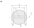
- FIG. FIG. 11 is an explanatory diagram for explaining measurement of the maximum diameter.
- FIG. 2 is a measurement diagram showing the element ratio of cobalt atoms in Example 1.
- FIG. 4 is a measurement diagram showing the real part ⁇ ′ of magnetic permeability and the imaginary part ⁇ ′′ of magnetic permeability in Example 1.
- FIG. 11 is a measurement diagram showing the element ratio of cobalt atoms in Example 2.
- FIG. 1 is a perspective view showing a first embodiment of an inductor component of the present invention
- FIG. 2 is an exploded view of the inductor component.
- FIG. 2 is a cross-sectional view
- FIG. 11 is a measurement diagram showing the real part ⁇ ′ of magnetic permeability and the imaginary part ⁇ ′′ of magnetic permeability in Example 2.
- FIG. 2 is a measurement diagram showing the element ratio of cobalt atoms in Comparative Example 1.
- FIG. 11 is a measurement diagram showing the real part ⁇ ′ of magnetic permeability and the imaginary part ⁇ ′′ of magnetic permeability in Comparative Example 1.
- Fig. 1 is a perspective see-through view showing a first embodiment of an inductor component 1.
- Fig. 2 is an exploded view of the inductor component 1.
- Fig. 3 is an X-X cross-sectional view of the inductor component 1.
- Fig. 4 is an explanatory diagram illustrating an internal magnetic member of the inductor component 1.
- Fig. 5 is an explanatory diagram illustrating measurement of the maximum diameter D.
- the inductor component 1 has an element body 10, a coil 20 provided on the element body 10, and a first external electrode 30 and a second external electrode 40 provided on the element body 10 and electrically connected to the coil.
- the inductor component 1 is electrically connected to wiring on a circuit board (not shown) via the first and second external electrodes 30, 40.
- the inductor component 1 is used, for example, as an impedance matching coil (matching coil) for high-frequency circuits, and is used in electronic devices such as personal computers, DVD players, digital cameras, TVs, mobile phones, car electronics, and medical and industrial machinery.
- the uses of the inductor component 1 are not limited to this, and it can also be used, for example, in tuning circuits, filter circuits, and rectifying and smoothing circuits.
- the base body 10 further includes an insulator 11, a first external magnetic member 61, a second external magnetic member 62, and an internal magnetic member 63.
- the insulator 11 includes glass. More specifically, the insulator 11 is made of a sintered glass. An example of the glass is borosilicate glass. The insulator 11 may further include non-magnetic ferrite, alumina, resin, etc. The insulator 11 is composed of a plurality of insulating layers stacked in the W direction. Each layer is in the form of a layer extending in the LT plane perpendicular to the stacking direction in the W direction. Note that, due to firing, etc., the interface between two adjacent layers may not be clearly defined.
- the element body 10 is formed in a substantially rectangular parallelepiped shape.
- the element body 10 includes a first end face 13 and a second end face 14 that face each other, a third end face 15 and a fourth end face 16 that face each other, a bottom face 17 connected between the first end face 13 and the second end face 14 and between the third end face 15 and the fourth end face 16, and a top face 18 that faces the bottom face 17.
- the outer surface of the element body 10 is composed of the first end face 13, the second end face 14 that faces the first end face 13, the third end face 15 that is connected between the first end face 13 and the second end face 14, the fourth end face 16 that faces the third end face 15, the bottom face 17 that is connected between the third end face 15 and the fourth end face 16, and the top face 18 that faces the bottom face 17.
- the L direction is perpendicular to the first end face 13 and the second end face 14
- the W direction is perpendicular to the third end face 15 and the fourth end face 16
- the T direction is perpendicular to the bottom face 17 and the top face 18.
- the L direction, W direction, and T direction are mutually orthogonal.
- the coil 20 has a helical structure in which the axis of the coil is parallel to the bottom surface 17 of the body 10 and is wound along the axis of the coil so as to intersect the third end surface 15 and the fourth end surface 16 of the body 10.
- the coil 20 is formed in a substantially rectangular shape when viewed from the axial direction, but is not limited to this shape.
- the shape of the coil 20 may be, for example, a circle, an ellipse, a rectangle, or another polygon.
- the axial direction of the coil 20 refers to a direction parallel to the central axis of the spiral around which the coil 20 is wound.
- the axial direction of the coil 20 and the lamination direction of the insulating layers are the same direction.
- "parallel” is not limited to a strict parallel relationship, but also includes a substantial parallel relationship, taking into account the range of realistic variation.
- the coil 20 includes coil wiring 21 wound along a plane.
- the multiple coil wirings 21 are stacked along the axial direction.
- the coil wiring 21 is formed by winding on the main surface (LT plane) of the insulating layer perpendicular to the axial direction.
- the coil wirings 21 adjacent to each other in the stacking direction are electrically connected in series through via wiring 26 that penetrates the insulating layer in the thickness direction (W direction). That is, the coil 20 includes coil wiring 21 and via wiring 26. In this way, the multiple coil wirings 21 are electrically connected in series to each other and form a spiral.
- the coil 20 has a configuration in which multiple coil wirings 21 are electrically connected in series to each other and have less than one turn stacked.
- the coil wiring 21 is composed of one coil conductor layer.
- the coil wiring 21 may be composed of multiple coil conductor layers stacked in surface contact with each other, in which case the coil wiring 21 can be formed with a high aspect ratio and a high degree of rectangularity.
- the coil wiring 21 may also be in a spiral shape with one or more turns.
- the coil 20 contains Ag.
- the coil 20 may contain conductive materials other than Ag (e.g., Cu, Au, etc.) and glass.
- the first external electrode 30 is L-shaped and extends from the first end face 13 to the bottom face 17.
- the second external electrode 40 is L-shaped and extends from the second end face 14 to the bottom face 17. In other words, the first and second external electrodes 30, 40 are both exposed to the bottom face 17.
- the first external electrode 30 is connected to the first end of the coil 20, and the second external electrode 40 is connected to the second end of the coil 20.
- the first external electrode 30 consists of two layers: a base electrode layer 31 and a plating film layer 32.
- the second external electrode 40 consists of two layers: a base electrode layer 41 and a plating film layer 42.
- the base electrode layer 31 is composed of multiple external electrode conductor layers 33 stacked in surface contact with each other.
- the base electrode layer 41 is composed of multiple external electrode conductor layers 43 stacked in surface contact with each other.
- the base electrode layers 31, 41 may be composed of conductive materials such as Ag, Cu, Au, and glass particles, or may be formed from the same material as the coil 20.
- the external electrode conductor layers 33 and 43 may be embedded in the element body 10, or may be formed on the outer surface of the element body 10.
- the plating film layers 32 and 42 are formed, for example, by Ni, Sn, Au, or Cu plating, and more specifically, by plating Ni and Sn.
- the first external magnetic member 61 and the second external magnetic member 62 are located outside the coil 20 in the axial direction of the coil 20.
- the first external magnetic member 61 constitutes the third end surface 15 of the base body 10
- the second external magnetic member 62 constitutes the fourth end surface 16 of the base body 10.
- the first external magnetic member 61 and the second external magnetic member 62 may contain a magnetic material and may be composed of a composite body of a resin and a magnetic material.
- a magnetic member means a member containing a magnetic material and does not have to contain resin.
- first and second external magnetic members 61, 62 may be laminated (coated) on the outer surface side of the first and second external magnetic members 61, 62 for the purpose of insulation and protection.
- other members such as an insulating layer made of a resin material or an inorganic material may be laminated (coated) on the outer surface side of the first and second external magnetic members 61, 62 for the purpose of insulation and protection.
- the internal magnetic member 63 is connected to the first external magnetic member 61 and the second external magnetic member 62.
- the internal magnetic member 63 is located inside the coil 20 in the axial direction of the coil 20.
- FIG. 4 is a schematic diagram showing region A of the internal magnetic member 63 in FIG. 3.
- the internal magnetic member 63 is composed of a composite body of resin 71 and magnetic particles 72 contained within the resin 71.
- the DC superposition characteristics can be improved compared to a magnetic layer made of ferrite.
- the resin 71 insulates between the magnetic particles 72, thereby reducing losses (eddy current losses and hysteresis losses) at high frequencies.
- the internal magnetic member 63 may be composed of the same material as the first external magnetic member 61 and the second external magnetic member 62.
- the resin 71 is, for example, an epoxy resin.
- the magnetic particle 72 is a single particle.
- the magnetic particle 72 may be an aggregate of a plurality of particles (i.e., an aggregate of particles that are not connected but simply assembled), or may be an agglomerate of a plurality of particles that are sintered or connected.
- the magnetic particles 72 are made of an alloy containing iron (Fe), nickel (Ni), and cobalt (Co).
- the alloy may be an amorphous alloy.
- the magnetic particle 72 has a maximum diameter D, a non-measurement range Z', a measurement range Z, a straight line L1 along the maximum diameter D, and a measurement region Y.
- the maximum diameter D is the largest diameter in the cross section of the magnetic particle 72. If the cross section of the magnetic particle 72 is elliptical, the maximum diameter D means the maximum length in the long axis direction, and if the magnetic particle 72 is an aggregate or agglomerate, the maximum diameter D means the maximum length in that cross section.
- the maximum diameter D may be the maximum diameter of the magnetic particle 72 in any cross section, and it is not necessary to select a cross section in which the longest diameter of the magnetic particle 72 appears.
- the measurement range Z and the non-measurement range Z' exist on the maximum diameter D.
- the sum of the measurement range Z and the non-measurement range Z' is the maximum diameter D. If the maximum diameter D is 100%, the non-measurement range Z' represents 10% along the maximum diameter D from the surface of the magnetic particle 72.
- the measurement range Z represents a range of 10 to 90% from one surface of the magnetic particle 72 along the maximum diameter D.
- the straight line L1 is arranged along the maximum diameter D.
- the measurement area Y refers to an area included in a certain width in the direction perpendicular to the straight line L1 in the measurement range Z.
- certain width means the aspect ratio, i.e., the ratio to the maximum diameter D, is -2.5% to 2.5% with respect to the maximum diameter D being 100%.
- the elemental proportion of the cobalt element which will be described later, is measured.
- “measurement along the maximum diameter” refers to measurement in the measurement area Y.
- the variation in the elemental ratio of the cobalt element in the measurement region Y is 19 atom% or less, preferably 9 atom% or less.
- the lower limit of the variation in the elemental ratio of the cobalt element is, for example, 1 atom% or more, more preferably 2 atom% or more.
- the elemental ratio of the cobalt element (atom%, elemental percentage) can be calculated from the ratio of the cobalt element to the total of the iron element, the nickel element, and the cobalt element, that is, 100 x Co/(Fe + Ni + Co). By having such an elemental ratio, the composition variation in the magnetic particle 72 can be suppressed.
- the variation in the relative magnetic permeability in the magnetic particle 72 can be reduced, and magnetic loss can be reduced.
- the variation in the elemental ratio of the cobalt element may be within the above numerical range in the measurement region Y in any cross section of the magnetic particle 72. If the variation in the element ratio of cobalt element in measurement region Y in any cross section of magnetic particle 72 is within the above numerical range, magnetic loss can be reduced compared to when it is outside the above numerical range.
- the elemental proportion of cobalt element is measured as follows.
- a cross section is formed from the internal magnetic member 63 using a focused ion beam (FIB).
- FIB focused ion beam
- one arbitrarily selected magnetic particle 72 is selected.
- An electron beam is irradiated in the maximum diameter D direction of the magnetic particle 72 using energy dispersive X-ray spectroscopy (TEM/EDX).
- TEM/EDX energy dispersive X-ray spectroscopy
- the difference between the maximum and minimum values of the cobalt element in the measurement area Y is obtained, and this difference is defined as the "variation in the element ratio of the cobalt element." Since the lower detection limit of TEM/EDX is considered to be about 1 atom%, values below 1 atom% are determined to be undetectable.
- the particle size of the magnetic particles 72 is, for example, 1 ⁇ m or less. During the manufacturing stage of the inductor component 1, the particle size of the magnetic particles 72 can be measured using an electron microscope. When the particle size of the magnetic particles 72 is 1 ⁇ m or less, the DC superposition characteristics are further improved, and the fine powder can reduce iron loss at high frequencies.
- the particle size of the magnetic particles 72 is, for example, 0.1 ⁇ m or more. In this case, uniform dispersion in the resin becomes easier, and the manufacturing efficiency of the internal magnetic member 63 is improved.
- the content of the magnetic particles 72 is preferably 20 vol% or more and 70 vol% or less with respect to the entire internal magnetic member 63.
- the variation in relative permeability is, for example, 2.5% or less, specifically 1.5% or less.
- the variation in relative permeability means the difference between the maximum and minimum values of relative permeability in the range of 200 MHz to 2 GHz.
- loss increases on the low frequency side compared to when the relative permeability is uniform.
- magnetic loss can be suppressed, particularly on the low frequency side, in the same way as when the relative permeability is uniform.
- an inductor component containing magnetic particles 72 is used as a matching component in an electric circuit, magnetic particles 72 with little variation in relative permeability can be easily used.
- the variation in relative permeability is measured as follows.
- the frequency characteristics of the relative permeability are measured in the range of 200 MHz to 2 GHz for a composite body of resin 71 and magnetic particles 72.
- the average value of the relative permeability and the maximum and minimum values derived from magnetic resonance are obtained, and the difference between the maximum and minimum values when the average value of the relative permeability is set to 100% is obtained.
- the fluctuation of the relative permeability due to magnetic resonance means the difference between the maximum and minimum values.
- the maximum value means the point with the largest fluctuation in the positive direction
- the minimum value means the point with the largest fluctuation in the negative direction.
- the average Q value is a good value.
- the average Q value is obtained by calculating the Q value in the range of 200 MHz to 2 GHz and calculating the average value of the Q values.
- the Q value means ⁇ '/ ⁇ ", which is the ratio of the real part ⁇ ' of the magnetic permeability to the imaginary part ⁇ " of the magnetic permeability.
- the average Q value is, for example, 5.0 ⁇ 10 1 or more, and specifically, 1.0 ⁇ 10 3 or more.
- the real part ⁇ ' of the effective magnetic permeability is the magnetic permeability of the part that actually functions as an inductor
- the imaginary part ⁇ " of the magnetic permeability indicates a value related to loss.
- the present invention is not limited to the first embodiment described above, and the design can be modified without departing from the gist of the present invention.
- the magnetic member may have at least one particle that satisfies the above conditions. In the magnetic member, preferably, all particles satisfy the above conditions.
- the magnetic particles 72 may be used for other purposes.
- the magnetic particles 72 may also be used as a radio wave absorbent.
- the magnetic particles 72 may be used in electronic components such as capacitor components.
- the cobalt element in the magnetic particles 72 is measured as follows.
- the magnetic particles 72 are fixed with a holder such as the resin 71 of the present invention to form a sheet shape, and then a cross section is formed using FIB as described above.
- a cross section is formed using FIB as described above.
- an electron beam is irradiated in the direction of maximum diameter D of the magnetic particles 72 using TEM/EDX.
- the difference between the maximum and minimum values of the cobalt element in the measurement region Y is obtained, and this difference is defined as the "variation in the element ratio of the cobalt element.”
- the magnetic particles 72 can be used as a sheet-like magnetic material containing magnetic particles.
- radio wave loss is caused at a specific frequency, and control can be performed to prevent the radio waves from entering.
- the cobalt element in the magnetic member is measured as follows. A composite body is formed of resin 71 and magnetic particles 72 contained within the resin 71, and the composite body is formed into a sheet shape, and then a cross section is formed using FIB as described above. Five arbitrarily selected magnetic particles 72 are selected from the cross section. An electron beam is irradiated in the maximum diameter D direction of each of the five magnetic particles 72 using TEM/EDX. For each magnetic particle 72, the difference between the maximum and minimum values of the cobalt element in the measurement area Y is obtained, and the largest difference is taken as the "variation in the element ratio of cobalt element."
- the materials are not limited to those exemplified above, and any known material can be used.
- the present disclosure includes the following aspects.
- ⁇ 1> A magnetic particle, in which the difference between the maximum and minimum values measured along the maximum diameter in a cross section of the elemental ratio of cobalt to the total of iron, nickel, and cobalt in the cross section is 19 atom % or less.
- ⁇ 2> The magnetic particle according to ⁇ 1>, wherein the difference between the maximum value and the minimum value is 9 atom % or less.
- ⁇ 3> The magnetic particles according to ⁇ 1> or ⁇ 2>, having a particle size of 1 ⁇ m or less.
- ⁇ 4> A magnetic member comprising a resin and the magnetic particles according to any one of ⁇ 1> to ⁇ 3> contained in the resin.
- An inductor component comprising: an element body including the magnetic member according to ⁇ 4>; and a coil provided within the element body.
- Example 1 Iron sulfate heptahydrate, cobalt sulfate heptahydrate, and nickel sulfate hexahydrate (all manufactured by Wako Pure Chemical Industries, Ltd.) were added to pure water and stirred and dissolved using a magnetic stirrer to prepare a metal salt solution.
- Acetone Nacalai Tesque
- the resulting powder was allowed to air dry on a metal tray for 3 hours and then collected.
- Example 1 The powder obtained in Example 1 was mixed with an epoxy resin and formed into a sheet using a doctor blade. A sheet of 5 mm x 18 mm was cut out from the sheet, and the thickness of the sheet was measured using a micrometer.
- the above sheet was cross-sectionally processed using FIB (Hitachi High-Tech SMI-3050R), and the cross section was irradiated with an electron beam using TEM/EDX (JEOL JEM-F200/Noran System 7) to perform line scanning.
- the elemental ratios of iron, cobalt, and nickel elements were measured.
- the measurement of the elemental ratio for example, when the maximum diameter D of the magnetic particles is 100 nm, the left and right ends of 10 nm are set as non-measurement ranges Z', and the central area of 80 nm in total, which is the range of 10 to 90 nm, is set as the measurement range Z.
- Measurement points were provided on L1 with an interval of 0.5 nm, and the elemental ratio was measured in the measurement area Y.
- the width of the measurement area Y was in the range of -2.5% to 2.5% with respect to the maximum diameter D. From the obtained elemental ratio, the elemental ratio Co/(Fe+Ni+Co) ⁇ 100 of the cobalt element was calculated. The results are shown in FIG. 6A and Table 1.
- Example 2 Except for changing the liquid delivery rate to 10.0 ml per minute, the same operation as in Example 1 was carried out. The results are shown in Figures 7A and 7B and Tables 1 and 2.
- Example 1 As shown in Comparative Example 1, when the variation in the element ratio of the cobalt element was high, the variation in the relative permeability was large and the average value of the Q value (Qave) was small. In other words, it was found that when the variation in the element ratio of the cobalt element was high, composition unevenness occurred in the magnetic particles. In contrast, in Example 1, the compositional variation was controlled with the variation in the element ratio of cobalt being 19 atom %. In Example 1, the variation in the relative permeability of the magnetic particles was small, the magnetic loss was reduced, and the average value of the Q value was small. Furthermore, in Example 2, the variation in the element ratio of cobalt element was 9 atom %, and the composition variation was further controlled. Therefore, in Example 2, the variation in the relative permeability of the magnetic particles was smaller, the magnetic loss was further reduced, and the average value of the Q value was further reduced.
Landscapes
- Engineering & Computer Science (AREA)
- Power Engineering (AREA)
- Chemical & Material Sciences (AREA)
- Dispersion Chemistry (AREA)
- Physics & Mathematics (AREA)
- Microelectronics & Electronic Packaging (AREA)
- Spectroscopy & Molecular Physics (AREA)
- Electromagnetism (AREA)
- Chemical Kinetics & Catalysis (AREA)
- General Chemical & Material Sciences (AREA)
- Manufacturing & Machinery (AREA)
- Mechanical Engineering (AREA)
- Coils Or Transformers For Communication (AREA)
Priority Applications (2)
| Application Number | Priority Date | Filing Date | Title |
|---|---|---|---|
| CN202380089960.7A CN120457503A (zh) | 2023-01-16 | 2023-08-24 | 磁性粒子 |
| JP2024571604A JPWO2024154373A1 (https=) | 2023-01-16 | 2023-08-24 |
Applications Claiming Priority (2)
| Application Number | Priority Date | Filing Date | Title |
|---|---|---|---|
| JP2023004637 | 2023-01-16 | ||
| JP2023-004637 | 2023-12-26 |
Publications (1)
| Publication Number | Publication Date |
|---|---|
| WO2024154373A1 true WO2024154373A1 (ja) | 2024-07-25 |
Family
ID=91955784
Family Applications (1)
| Application Number | Title | Priority Date | Filing Date |
|---|---|---|---|
| PCT/JP2023/030537 Ceased WO2024154373A1 (ja) | 2023-01-16 | 2023-08-24 | 磁性粒子 |
Country Status (3)
| Country | Link |
|---|---|
| JP (1) | JPWO2024154373A1 (https=) |
| CN (1) | CN120457503A (https=) |
| WO (1) | WO2024154373A1 (https=) |
Citations (1)
| Publication number | Priority date | Publication date | Assignee | Title |
|---|---|---|---|---|
| JP2022138129A (ja) * | 2021-03-09 | 2022-09-22 | 住友金属鉱山株式会社 | (Fe)-ニッケル(Ni)系合金粉、前記合金粉を含む圧粉体又はシート、並びに前記圧粉体又はシートを備えたインダクタ、リアクトル、チョークコイル、ノイズフィルタ、トランス、回転機、発電機、又は電波吸収体 |
-
2023
- 2023-08-24 JP JP2024571604A patent/JPWO2024154373A1/ja active Pending
- 2023-08-24 WO PCT/JP2023/030537 patent/WO2024154373A1/ja not_active Ceased
- 2023-08-24 CN CN202380089960.7A patent/CN120457503A/zh active Pending
Patent Citations (1)
| Publication number | Priority date | Publication date | Assignee | Title |
|---|---|---|---|---|
| JP2022138129A (ja) * | 2021-03-09 | 2022-09-22 | 住友金属鉱山株式会社 | (Fe)-ニッケル(Ni)系合金粉、前記合金粉を含む圧粉体又はシート、並びに前記圧粉体又はシートを備えたインダクタ、リアクトル、チョークコイル、ノイズフィルタ、トランス、回転機、発電機、又は電波吸収体 |
Also Published As
| Publication number | Publication date |
|---|---|
| JPWO2024154373A1 (https=) | 2024-07-25 |
| CN120457503A (zh) | 2025-08-08 |
Similar Documents
| Publication | Publication Date | Title |
|---|---|---|
| CN108292555B (zh) | 功率电感器 | |
| US10867744B2 (en) | Coil component | |
| JP5175884B2 (ja) | ナノ粒子複合材料、それを用いたアンテナ装置及び電磁波吸収体 | |
| CN104575937B (zh) | 片式电子组件及其制造方法 | |
| CN104347228B (zh) | 片式电子组件及其制造方法 | |
| CN104766692B (zh) | 芯片电子组件 | |
| CN108701539B (zh) | 线圈图案及其形成方法以及具有线圈图案的芯片装置 | |
| CN106688063A (zh) | 功率电感器 | |
| JP2018098278A (ja) | コイル部品 | |
| US20180308629A1 (en) | Coil component | |
| TW201611052A (zh) | 功率電感器 | |
| JP2018056472A (ja) | コイル部品 | |
| CN114207748B (zh) | 软磁性粉末及其制造方法、使用软磁性粉末的线圈部件以及使用软磁性粉末的磁性材料的制造方法 | |
| US12288639B2 (en) | Coil component and method of manufacturing the same | |
| CN103733280B (zh) | 层叠线圈部件及其制造方法 | |
| JP2022177573A (ja) | コイル封入磁心およびコイル部品 | |
| WO2018181957A1 (ja) | 複合磁性体、複合磁性体を含む基板、およびこれらを含む高周波電子部品 | |
| WO2024154373A1 (ja) | 磁性粒子 | |
| CN103563016A (zh) | 金属粉末和电子部件 | |
| KR20160014936A (ko) | 복합 자성 분말 및 그를 이용한 칩 코일 부품 | |
| JP7385469B2 (ja) | 電子部品 | |
| WO2025011323A1 (zh) | 一种手机nfc天线及其吸波材料的制备方法 | |
| JP6812886B2 (ja) | 高周波電子部品 | |
| US20190006095A1 (en) | Coil component and lc composite component | |
| JP6955382B2 (ja) | 積層コイル |
Legal Events
| Date | Code | Title | Description |
|---|---|---|---|
| 121 | Ep: the epo has been informed by wipo that ep was designated in this application |
Ref document number: 23917586 Country of ref document: EP Kind code of ref document: A1 |
|
| WWE | Wipo information: entry into national phase |
Ref document number: 2024571604 Country of ref document: JP |
|
| WWE | Wipo information: entry into national phase |
Ref document number: 202380089960.7 Country of ref document: CN |
|
| WWP | Wipo information: published in national office |
Ref document number: 202380089960.7 Country of ref document: CN |
|
| NENP | Non-entry into the national phase |
Ref country code: DE |
|
| 122 | Ep: pct application non-entry in european phase |
Ref document number: 23917586 Country of ref document: EP Kind code of ref document: A1 |