WO2024154331A1 - 端末、無線通信方法及び基地局 - Google Patents
端末、無線通信方法及び基地局 Download PDFInfo
- Publication number
- WO2024154331A1 WO2024154331A1 PCT/JP2023/001698 JP2023001698W WO2024154331A1 WO 2024154331 A1 WO2024154331 A1 WO 2024154331A1 JP 2023001698 W JP2023001698 W JP 2023001698W WO 2024154331 A1 WO2024154331 A1 WO 2024154331A1
- Authority
- WO
- WIPO (PCT)
- Prior art keywords
- csi
- information
- trp
- reported
- report
- Prior art date
- Legal status (The legal status is an assumption and is not a legal conclusion. Google has not performed a legal analysis and makes no representation as to the accuracy of the status listed.)
- Ceased
Links
Images







Classifications
-
- H—ELECTRICITY
- H04—ELECTRIC COMMUNICATION TECHNIQUE
- H04B—TRANSMISSION
- H04B7/00—Radio transmission systems, i.e. using radiation field
- H04B7/02—Diversity systems; Multi-antenna system, i.e. transmission or reception using multiple antennas
- H04B7/04—Diversity systems; Multi-antenna system, i.e. transmission or reception using multiple antennas using two or more spaced independent antennas
- H04B7/0413—MIMO systems
- H04B7/0456—Selection of precoding matrices or codebooks, e.g. using matrices antenna weighting
Definitions
- This disclosure relates to terminals, wireless communication methods, and base stations in next-generation mobile communication systems.
- LTE Long Term Evolution
- UMTS Universal Mobile Telecommunications System
- Non-Patent Document 1 LTE-Advanced (3GPP Rel. 10-14) was specified for the purpose of achieving higher capacity and greater sophistication over LTE (Third Generation Partnership Project (3GPP (registered trademark)) Release (Rel.) 8, 9).
- LTE 5th generation mobile communication system
- 5G+ 5th generation mobile communication system
- 6G 6th generation mobile communication system
- NR New Radio
- E-UTRA Evolved Universal Terrestrial Radio Access
- E-UTRAN Evolved Universal Terrestrial Radio Access Network
- CSI channel state information
- MTRP Multi TRP
- UE User Equipment
- CJT Coherent joint transmission
- one of the objectives of this disclosure is to provide a terminal, a wireless communication method, and a base station that determine an appropriate CSI/codebook.
- a terminal has a receiving unit that receives a setting for Doppler CSI, and a control unit that determines whether to report a bitmap indicating the positions of non-zero coefficients for the Doppler CSI based on the setting.
- CSI can be appropriately reported.
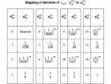
- FIG. 1 shows an example of a 16-level quantization table.
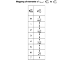
- FIG. 2 shows an example of an 8-level quantization table.
- 3A and 3B show an example of an extended type 2-port selection codebook.
- 4A and 4B show an example of an extended type 2-port selection codebook.
- 5 shows an example of parameter combinations for a Rel.16 Type 2 codebook.
- 6 shows an example of parameter combinations for a Rel.17 type 2-port selective codebook.
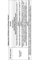
- FIG. 7 shows an example of a mapping order of CSI fields in CSI Part 1 of one CSI report.
- FIG. 1 shows an example of a 16-level quantization table.
- FIG. 2 shows an example of an 8-level quantization table.
- 3A and 3B show an example of an extended type 2-port selection codebook.
- 4A and 4B show
- FIG. 9 shows an example of a bitmap for indicating the positions of NZCs in Doppler CSI.
- FIG. 10 shows an example of an operation according to embodiment #1.
- FIG. 11 shows an example of an operation according to embodiment #2.
- FIG. 12 is a diagram illustrating an example of a schematic configuration of a wireless communication system according to an embodiment.
- FIG. 13 is a diagram illustrating an example of the configuration of a base station according to an embodiment.
- FIG. 14 is a diagram illustrating an example of the configuration of a user terminal according to an embodiment.
- FIG. 15 is a diagram illustrating an example of the hardware configuration of a base station and a user terminal according to an embodiment.
- FIG. 16 is a diagram illustrating an example of a vehicle according to an embodiment.
- a terminal also referred to as a user terminal, User Equipment (UE), etc.
- UE User Equipment
- CSI channel state information
- a network e.g., a base station
- the CSI may be transmitted to the base station, for example, using an uplink control channel (e.g., a Physical Uplink Control Channel (PUCCH)) or an uplink shared channel (e.g., a Physical Uplink Shared Channel (PUSCH)).
- PUCCH Physical Uplink Control Channel
- PUSCH Physical Uplink Shared Channel
- the RS used to generate the CSI may be, for example, at least one of a Channel State Information Reference Signal (CSI-RS), a Synchronization Signal/Physical Broadcast Channel (SS/PBCH) block, a Synchronization Signal (SS), a DeModulation Reference Signal (DMRS), etc.
- CSI-RS Channel State Information Reference Signal
- SS/PBCH Synchronization Signal/Physical Broadcast Channel
- SS Synchronization Signal
- DMRS DeModulation Reference Signal
- the CSI-RS may include at least one of a Non-Zero Power (NZP) CSI-RS and a CSI-Interference Management (CSI-Interference Measurement, CSI-IM).
- the SS/PBCH block is a block including an SS and a PBCH (and corresponding DMRS), and may be referred to as an SS block (SSB), etc.
- the SS may also include at least one of a Primary Synchronization Signal (PSS) and a Secondary Synchronization Signal (SSS).
- PSS Primary Synchronization Signal
- SSS Secondary Synchronization Signal
- CSI is a channel quality indicator (CQI), a precoding matrix indicator (PMI), a CSI-RS resource indicator (CSI-RS Resource Indicator (CRI)), a SS/PBCH block resource indicator (SSBRI), and a layer indicator (Layer Indicator (LAI)).
- the L1-RSRP may include at least one of the following: L1-Level Indicator (LI), Rank Indicator (RI), L1-RSRP (Layer 1 Reference Signal Received Power), L1-RSRQ (Reference Signal Received Quality), L1-SINR (Signal to Interference plus Noise Ratio), and L1-SNR (Signal to Noise Ratio).
- L1-RSRP may include at least one of the following: L1-Level Indicator (LI), Rank Indicator (RI), L1-RSRP (Layer 1 Reference Signal Received Power), L1-RSRQ (Reference Signal Received Quality), L1-SINR (Signal to Interference plus Noise Rati
- the UE may receive information regarding CSI reporting (report configuration information) and control CSI reporting based on the report configuration information.
- the report configuration information may be, for example, "CSI-ReportConfig" of the information element (IE) of Radio Resource Control (RRC).
- IE information element
- RRC Radio Resource Control
- RRC IE may be interchangeably read as RRC parameters, higher layer parameters, etc.
- the reporting configuration information may include, for example, at least one of the following: Information regarding the type of CSI report (report type information, e.g., RRC IE “reportConfigType”) Information on one or more quantities of CSI to be reported (one or more CSI parameters) (report quantity information, e.g., RRC IE “reportQuantity”) Information on the RS resource used to generate the amount (the CSI parameter) (resource information, for example, "CSI-ResourceConfigId" of the RRC IE) Information on the frequency domain to which the CSI is reported (frequency domain information, for example, the RRC IE "reportFreqConfiguration”)
- the report type information may indicate a periodic CSI (Periodic CSI (P-CSI)) report, an aperiodic CSI (A-CSI) report, or a semi-persistent CSI (Semi-Persistent CSI (SP-CSI)) report.
- P-CSI Period CSI
- A-CSI aperiodic CSI
- SP-CSI semi-persistent CSI
- the reporting amount information may also specify a combination of at least one of the above CSI parameters (e.g., CRI, RI, PMI, CQI, LI, L1-RSRP, etc.).
- CSI parameters e.g., CRI, RI, PMI, CQI, LI, L1-RSRP, etc.
- the resource information may also be an ID of a resource for the RS.
- the resource for the RS may include, for example, a non-zero power CSI-RS resource or SSB, and a CSI-IM resource (for example, a zero power CSI-RS resource).
- the frequency domain information may also indicate the frequency granularity of the CSI reporting.
- the frequency granularity may include, for example, a wideband and a subband.
- the wideband is the entire CSI reporting band.
- the wideband may be, for example, the entirety of a certain carrier (Component Carrier (CC)), cell, serving cell), or the entirety of a bandwidth part (BWP) within a certain carrier.
- CC Component Carrier
- BWP bandwidth part
- the wideband may also be referred to as the CSI reporting band, the entire CSI reporting band, etc.
- a subband may be a part of a wideband and may be composed of one or more resource blocks (RBs or PRBs).
- the size of the subband may be determined according to the size of the BWP (number of PRBs).
- the frequency domain information may indicate whether wideband or subband PMI is to be reported (the frequency domain information may include, for example, the RRC IE "pmi-FormatIndicator" used to determine whether wideband PMI reporting or subband PMI reporting is to be performed).
- the UE may determine the frequency granularity of the CSI report (i.e., whether wideband PMI reporting or subband PMI reporting) based on at least one of the above reporting amount information and frequency domain information.
- one wideband PMI may be reported for the entire CSI reporting band
- subband PMI reporting is configured, a single wideband indication i 1 may be reported for the entire CSI reporting band, and one subband indication i 2 (e.g., one subband indication for each subband) may be reported for each of the one or more subbands within the entire CSI reporting band.
- the UE performs channel estimation using the received RS and estimates the channel matrix H.
- the UE feeds back an index (PMI) that is determined based on the estimated channel matrix.
- the PMI may indicate a precoder matrix (also referred to simply as a precoder) that the UE considers appropriate to use for downlink (DL) transmissions to the UE.
- a precoder matrix also referred to simply as a precoder
- Each value of the PMI may correspond to one precoder matrix.
- a set of PMI values may correspond to a set of different precoder matrices, called a precoder codebook (also referred to simply as a codebook).
- the CSI report may include one or more types of CSI.
- the CSI may include at least one of a first type (Type 1 CSI) used for selecting a single beam and a second type (Type 2 CSI) used for selecting multiple beams.
- Single beam may be rephrased as a single layer, and multiple beams may be rephrased as multiple beams.
- Type 1 CSI does not assume multi-user multiple input multiple output (MU-MIMO), and Type 2 CSI may assume multi-user MIMO.
- the codebook may include a codebook for type 1 CSI (also called a type 1 codebook, etc.) and a codebook for type 2 CSI (also called a type 2 codebook, etc.).
- Type 1 CSI may also include type 1 single-panel CSI and type 1 multi-panel CSI, and different codebooks (type 1 single-panel codebook, type 1 multi-panel codebook) may be defined for each.
- Type 1 and Type I may be interpreted as interchangeable.
- Type 2 and Type II may be interpreted as interchangeable.
- the uplink control information (UCI) type may include at least one of the following: Hybrid Automatic Repeat reQuest ACKnowledgement (HARQ-ACK), scheduling request (SR), and CSI.
- HARQ-ACK Hybrid Automatic Repeat reQuest ACKnowledgement
- SR scheduling request
- CSI CSI
- UCI may contain one CSI part for wideband PMI feedback.
- CSI report #n contains PMI wideband information if reported.
- UCI can contain two CSI parts for subband PMI feedback.
- CSI part 1 contains wideband PMI information.
- CSI part 2 contains one wideband PMI information and some subband PMI information.
- CSI part 1 and CSI part 2 are coded separately.
- the UE is configured by a higher layer with N (N ⁇ 1) CSI reporting configuration report settings and M (M ⁇ 1) CSI resource configuration resource settings.
- the CSI reporting configuration (CSI-ReportConfig) includes channel measurement resource settings (resourcesForChannelMeasurement), interference CSI-IM resource settings (csi-IM-ResourceForInterference), interference NZP-CSI-RS settings (nzp-CSI-RS-ResourceForInterference), and report quantity (reportQuantity).
- Each of the channel measurement resource settings, interference CSI-IM resource settings, and interference NZP-CSI-RS settings is associated with a CSI resource configuration (CSI-ResourceConfig, CSI-ResourceConfigId).
- the CSI resource configuration includes a list of CSI-RS resource sets (csi-RS-ResourceSetList, e.g., an NZP-CSI-RS resource set or a CSI-IM resource set).
- evaluation and provision of CSI reporting for DL multi-TRP and multi-panel transmissions at least one is being considered to enable more dynamic channel/interference hypotheses for NCJT.
- the UE is configured with parameters related to the codebook (CodebookConfig) by higher layer signaling (RRC signaling).
- the codebook configuration is included in the CSI report configuration (CSI-ReportConfig) of the higher layer (RRC) parameters.
- At least one codebook is selected from a number of codebooks including type 1 single panel (typeI-SinglePanel), type 1 multi-panel (typeI-MultiPanel), type 2 (typeII), and type 2 port selection (typeII-PortSelection).
- the codebook parameters include parameters related to the codebook subset restriction (CBSR).
- CBSR codebook subset restriction
- the CBSR setting is a bit that indicates which PMI reports are allowed ('1') and which are not allowed ('0') for the precoder associated with the CBSR bit.
- One bit in the CBSR bitmap corresponds to one codebook index/antenna port.
- the CSI report configuration (CSI-ReportConfig) of Rel. 16 includes CSI-RS resources for channel measurement (resourcesForChannelMeasurement (CMR)), CSI-RS resources for interference measurement (csi-IM-ResourcesForInterference (ZP-IMR), nzp-CSI-RS-ResourcesForInterference (NZP-IMR)), etc.
- CMR channel measurement
- ZP-IMR CSI-RS resources for interference measurement
- NZP-IMR nzp-CSI-RS-ResourcesForInterference
- parameters other than codebookConfig-r16 are also included in the CSI report configuration of Rel. 15.
- an extended CSI reporting configuration (CSI-ReportConfig) is being considered for CSI measurement/reporting of multi-TRP using NCJT.
- CSI-ReportConfig two CMR groups corresponding to each of the two TRPs are configured.
- the CMRs in the CMR group may be used for at least one measurement of multi-TRP and single-TRP using NCJT.
- the N CMR pairs of the NCJT are configured by RRC signaling.
- the UE may be configured by RRC signaling whether to use a CMR of a CMR pair for single-TRP measurement.
- the UE may be configured to report one CSI associated with the best measurement result among the measurement hypotheses for the NCJT and single TRP.
- the CBSR is set for each codebook setting for each CSI reporting setting.
- the CBSR applies to all CMRs, etc. within the corresponding CSI reporting setting.
- Option 2 Measure both the CSI of the NCJT and the CSI of a single TRP.
- Type 1 codebook (Rel. 15) specifies a type 1 single panel codebook and a type 1 multi-panel codebook for base station panels.
- type 1 single panel an antenna model of a CSI antenna port array (logical configuration) is specified for (N 1 ,N 2 ). The number of CSI-RS antenna ports P CSI-RS is 2N 1 N 2.
- type 1 multi-panel an antenna model of a CSI antenna port array (logical configuration) is specified for (N g ,N 1 ,N 2 ) and the number of CSI-RS antenna ports P CSI-RS .
- the composite codebook index i1 [ i1,1 i1,2 i1,3 ].
- i 1 may be the index for the wideband,
- the supported settings ( N1 , N2 ) and ( O1 , O2 ) (combinations of values) are specified.
- ( N1 , N2 ) indicates the number of antenna elements in two dimensions (2D) and is set by the higher layer parameter n1 - n2 in moreThanTwo in nrOfAntennaPorts in typeI- SinglePanel .
- n1-n2 are N1O1N2O2 - bit bitmap parameters.
- O1 , O2 ) is the 2D oversampling factor.
- Type-1 multi-panel CSI compared to Type-1 single panel, the number of panels Ng is set in addition to N1 and N2 .
- the same SD beam (precoding matrix Wl ) is selected for each panel, and only inter-panel co-phasing is added and reported.
- the supported (N g ,N 1 ,N 2 ) and (O 1 ,O 2 ) configurations are specified in the specification.
- (N 1 ,N 2 ) are configured by ng-n1-n2 in typeI-MultiPanel.
- i 1,1 is ⁇ 0,1,...,N 1 O 1 -1 ⁇ .
- i 1,2 is ⁇ 0,1,...,N 2 O 2 -1 ⁇ .
- i 2 is ⁇ 0,1,2,3 ⁇ .
- the matrix for 1-layer CSI reporting codebook using antenna ports 3000 to 2999+P CSI-RS is W_i 1,1 ,i 1,2 ,i 1,4 ,i 2 ⁇ (1).
- W l,m,p,n (1) W l,m,p,n ⁇ 1,N g ,1.
- ⁇ n e j ⁇ n/2 .
- ⁇ _p 1 , ⁇ _p 2 , ⁇ _p 3 represent inter-panel phase matching.
- the same beams (SD beam matrix, precoding matrix W l ) are selected for panels 0, 1, 2, and 3, ⁇ _p 1 represents the phase compensation of panel 1 relative to panel 0, ⁇ _p 2 represents the phase compensation of panel 2 relative to panel 0, and ⁇ _p 3 represents the phase compensation of panel 3 relative to panel 0.
- a matrix Z with X rows and Y columns may be expressed as Z(X ⁇ Y).
- N t is the number of antennas/antenna ports.
- N 3 is the total number of precoding (beamforming) matrices (precoders) (number of subbands) indicated by the PMI.
- W 1 (N t ⁇ 2L) is a matrix (SD beam matrix) consisting of L ⁇ ⁇ 2,4 ⁇ (oversampled) spatial domain (SD) 2D DFT vectors (SD beams, 2D-DFT vectors).
- W 2,l (2L ⁇ N 3 ) is a matrix (LC coefficient matrix) consisting of linear combination coefficients (LC coefficients, subband complex LC coefficients, combination coefficients) for layer l.
- W 2,l represents beam selection and co-phasing between two polarizations.
- two W 2,l are c i , c j respectively.
- the feedback overhead is mainly due to the LC coefficient matrix W 2,l .
- Type-2 CSI in Rel. 15 only supports ranks 1 and 2.
- Type-2 CSI the channel (channel matrix) for a user is represented by a linear combination of two polarizations and L beams (L 2D-DFT vectors). Rel. 15 Type-2 CSI supports ranks 1 and 2.
- Type-2 CSI (enhanced Type-2 codebook) in Rel. 16 reduces the overhead associated with W2 ,l through frequency domain (FD) compression.
- Type-2 CSI in Rel. 16 supports ranks 3 and 4 in addition to ranks 1 and 2.
- W 2,l is approximated by W ⁇ l W f,l H.
- the matrix W ⁇ may be expressed as W with ⁇ (w tilde) above it.
- W ⁇ l may be expressed as W ⁇ 2,l .
- the matrix W f,l H is the adjoint matrix of W f,l and is obtained by conjugate transpose of W f,l .
- the UE may be configured with one of two subband sizes.
- the subband (CQI subband) is defined as N PRB SB contiguous PRBs and may depend on the total number of PRBs in the BWP.
- the number of PMI subbands per CQI subband R is configured by the RRC IE (numberOfPMI-SubbandsPerCQI-Subband). R controls the total number of precoding matrices N3 represented by the PMI as a function of the number of subbands configured in the csi-ReportingBand, the subband size configured by subbandSize, and the total number of PRBs in the BWP.
- W 1 (N t ⁇ 2L) is a matrix consisting of multiple (oversampled) spatial domain (SD) 2D-DFT (vector, beam).
- SD spatial domain
- 2D-DFT 2D discrete Fourier transform
- the spatial domain response/distribution represented by the SD 2D-DFT vector may be called the SD beam.
- W ⁇ l (2L ⁇ Mv ) is a matrix of LC coefficients for which up to K0 non-zero coefficients (NZCs, LC coefficients with non-zero amplitude) are reported.
- the report consists of two parts: a bitmap capturing the NZC positions and the quantized NZCs.
- W f,l (N 3 ⁇ M v ) is a matrix of frequency domain (FD) bases (vectors) for layer l.
- N 3 is the total number of precoding (beamforming) matrices (precoders) indicated by the PMI as a function of the number of subbands configured in the csi-ReportingBand.
- the csi-ReportingBand indicates the contiguous or non-contiguous subbands in a BWP for which CSI for that BWP is reported.
- C(N 3 ⁇ 1,M v ⁇ 1) represents the number of combinations (combinatorial coefficient C(x,y)) of selecting M v ⁇ 1 from N 3 ⁇ 1, and is also called the binomial coefficient.
- the frequency domain response/distribution (frequency response) represented by a linear combination of the FD basis vectors and the LC coefficients may be called an FD beam.
- the FD beam may correspond to a delay profile (time response).
- the PMI subband size is given by CQI subband size/R, where R ⁇ 1,2 ⁇ .
- the number of FD bases Mv for a given rank v is given by ceil( pv ⁇ N3 /R).
- the number of FD bases is the same for all layers l ⁇ 1,2,3,4 ⁇ . pv is set by higher layers.
- the dominant M v FD bases are selected. By letting M v ⁇ N 3 , the overhead of W ⁇ l is much smaller than that of W 2,l . All or a part of the M v FD bases are used to approximate the frequency response of each SD beam. A bitmap is used to report only the selected FD bases for each SD beam. If no bitmap is reported, all FD bases are selected for each SD beam. In this case, the NZCs of all FD bases are reported for each SD beam.
- K l NZ ⁇ K 0 ceil( ⁇ ⁇ 2LM v )
- K NZ ⁇ 2K 0 ceil( ⁇ ⁇ 2LM v )
- Type 2 CSI feedback on PUSCH in Rel. 16 includes two parts.
- CSI Part 1 has a fixed payload size and is used to identify the number of information bits in CSI Part 2.
- the size of Part 2 is variable (UCI size depends on the number of NZCs, which is not known to the base station).
- the UE reports the number of NZCs in CSI Part 1, which determines the size of CSI Part 2.
- the base station After receiving CSI Part 1, the base station knows the size of CSI Part 2.
- CSI Part 1 includes RI (if reported), CQI, and an indicator of the total number of non-zero amplitude coefficients across layers for enhanced Type-2 CSI.
- the fields in Part 1, RI (if reported), CQI, and an indicator of the total number of non-zero amplitude coefficients across layers, are coded separately.
- CSI Part 2 includes the PMI for enhanced Type-2 CSI. Parts 1 and 2 are coded separately.
- the CSI part 2 includes at least one of the following: an oversampling factor; an index of the 2D-DFT basis; an index M initial of the initial DFT basis (starting offset) of the selected DFT window; a selected DFT basis per layer; NZC (amplitude and phase) per layer; a strongest coefficeint indicator (SCI) per layer; and an amplitude of the strongest coefficient per layer/polarization.
- the multiple PMI indices (PMI values, codebook indices) associated with different CSI Part 2 information may be as follows for the l-th layer: i1,1 : The two-dimensional oversampling factor [ q1q2 ], where q1 ⁇ ⁇ 0,1,..., O1-1 ⁇ and q2 ⁇ ⁇ 0,1 ,..., O2-1 ⁇ . i1,2 : (SD) 2D-DFT basis (beam) multiple indexes, i1,2 ⁇ 0,1,...,C( N1N2 , L)-1 ⁇ . i 1,5 : Codebook indicator. The index of the (FD)DFT basis for the selected DFT window. i 1,5 ⁇ 0,1,...,2M v -1 ⁇ .
- i1,6,l Codebook indicator.
- the (FD) DFT basis selected for the l-th layer. If N3 ⁇ 19, then i1,6,l ⁇ ⁇ 0,1,...,C(N3 ⁇ 1, Mv ⁇ 1) ⁇ 1 ⁇ . If N3 > 19, then i1,6,l ⁇ ⁇ 0,1,...,C( 2Mv ⁇ 1 , Mv ⁇ 1) ⁇ 1 ⁇ .
- kl,M_v-1 (3) [ kl,0,f (3) ... kl,M_v-1,f (3) ], kl,i,f (3) ⁇ ⁇ 0,1 ⁇ .
- i 1,8,l the strongest coefficient indicator for the l th layer (the largest element k l,i,f (2) in the amplitude coefficient indicator).
- f l * ⁇ ⁇ 0,1,...,M v -1 ⁇ be the index of i 2,4,l and i l * ⁇ ⁇ 0,1,...,2L-1 ⁇ be the index of k l,f_l ⁇ * (2) .
- i 2,4,l , i 2,5,l and i 1,7,l denote the amplitude coefficient, phase coefficient and bitmap, respectively, after remapping.
- Each reported LC coefficient (complex coefficient) in ⁇ tilde over (W ) ⁇ l is separately quantized in amplitude and phase.
- the polarization-specific reference amplitude is quantized to 16 levels using the table in Figure 1 (mapping of elements in the amplitude coefficient indicator i2,3,l : mapping of amplitude coefficient indicator element kl ,p (1) to amplitude coefficient pl ,p (1) ).
- i1,5 and i1,6,l are PMI indices for (FD)DFT basis reporting. i1,5 is reported only if N3 >19.
- beam index i 0,1,...,L-1
- m1 (i) O1n1 (i) + q1
- m2 (i) O2n2 (i) + q2
- vm_1 ⁇ (i),m_2 ⁇ (i) denote SD(beam)-DFT bases
- pl,0 (1) and pl ,i,f (2) denote amplitude coefficients
- ⁇ l ,i,f denotes phase coefficients.
- the codebook for each layer includes the strongest coefficient for each polarization, the amplitude coefficient for each FD-DFT basis for each polarization, and the phase coefficient for each FD-DFT basis for each polarization.
- the PMI information is organized into three groups (groups 0 to 2) for CSI part 2 groupings. This is important in case of CSI omission.
- Each reported element with index i2,4,l , i2,5,l , and i1,7,l is associated with a specific priority rule.
- Type-1 CSI an SD beam represented by an SD DFT vector is sent towards the UE.
- Type-2 CSI L SD beams are linearly combined and sent towards the UE.
- Each SD beam can be associated with multiple FD beams.
- the channel frequency response can be obtained by linearly combining those FD basis vectors. The channel frequency response corresponds to the power delay profile.
- Type 2 port selection (PS) CSI (Type 2 PS codebook)
- PS Type 2 port selection
- the base station transmits CSI-RS using K CSI-RS ports that are beamformed considering a set of SD beams.
- the UE selects/identifies the best L( ⁇ K) CSI-RS ports per polarization and reports their indexes in W1 .
- Rel. 15 Type 2 PS CSI supports rank 1, 2.
- Rel. 16 Type-2 PS CSI (enhanced Type-2 PS codebook) is similar to Rel. 16 Type-2 CSI, except for SD beam selection.
- Rel. 15 Type-2 PS CSI supports ranks 1 to 4.
- W 1 (K ⁇ 2L) is a block diagonal matrix.
- W ⁇ l (2L ⁇ M) is the LC coefficient matrix.
- W f,l (N 3 ⁇ M) consists of N 3 FD-DFT basis vectors.
- K is set by upper layers.
- L is set by upper layers.
- each CSI-RS port #i is associated with an SD beam (b i ) (FIGS. 3A and 3B).
- Rel. 16 Type-2 PS CSI reduces overhead compared to Rel. 15 Type-2 PS CSI by reducing the number of FD bases from N3 to Mv ( Mv ⁇ N3 ) in the same manner as Rel. 16 Type-2 CSI.
- each CSI-RS port #i is associated with an SD-FD beam pair (pair of SD beam b i and FD beam f i,j, where j is the frequency index) instead of an SD beam (FIGS. 4A and 4B).
- ports 3 and 4 are associated with the same SD beam and different FD beams.
- the frequency selectivity of the channel frequency response observed at the UE based on an SD beam-FD beam pair can be reduced by delay pre-compensation compared to the frequency selectivity of the channel frequency response observed at the UE based on an SD beam.
- the main scenario for Type 2 port selection codebook in Rel. 17 is FDD.
- the channel reciprocity based on SRS measurement is not perfect (UL beam and DL beam angles may be different, UL and DL frequencies are different in FDD, and effective antenna spacing is different at the UL and DL frequencies).
- the base station can obtain/select some partial information (dominant angle and delay (SD beam and FD beam)).
- SD beam and FD beam CSI report
- the base station can obtain CSI for DL MIMO precoder decision. In this case, some CSI reports may be omitted to reduce CSI overhead.
- the values of ⁇ , M, ⁇ are determined by the upper layer parameter paramCombination-r17 (codebook parameter setting).
- Figure 5 shows an example of parameter combination for the Rel. 16 type 2 codebook.
- Figure 6 shows an example of parameter combination for the Rel. 17 type 2 port selection codebook.
- each CSI-RS port is beamformed using an SD beam and an FD basis vector.
- Each port is associated with an SD-FD pair.
- each matrix block consists of L columns of a K ⁇ K identity matrix.
- the base station transmits K beamformed CSI-RS ports. Each port is associated with an SD-FD pair.
- the UE selects L ports out of K and reports them to the base station as part of the PMI (W1 ,l ). Note that in Rel. 16, each port is associated with an SD beam.
- W ⁇ l (2L ⁇ Mv ) is a matrix of combination coefficients (subband complex LC coefficients). At most K0 NZCs are reported. The report consists of two parts: a bitmap capturing the NZC positions and the quantized NZCs. In certain cases the bitmap can be omitted. Note that in Rel. 16 the bitmap of NZC positions is always reported.
- W f,l (N 3 ⁇ M v ) is a matrix consisting of N 3 FD basis (FD-DFT basis) vectors. There are M v FD bases for each layer. The base station may turn off W f,l . When W f,l is on, M v additional FD bases are reported. When W f,l is off, no additional FD bases are reported. Note that in Rel. 16, W f,l is always reported.
- the CSI report comprises two parts.
- Part 1 has a fixed payload size and is used to identify the number of information bits in Part 2.
- Part 1 is transmitted in its entirety before Part 2.
- Part 1 contains the RI (if reported), CQI, and an indication of the total number of non-zero amplitude coefficients across layers.
- the fields in Part 1, RI (if reported), CQI, and an indication of the total number of non-zero amplitude coefficients across layers, are coded separately.
- Part 2 contains the PMI of the Enhanced Type 2 or Additional Enhanced Type 2 Port Selection CSI. Parts 1 and 2 are coded separately.
- Figure 7 shows an example of a mapping order of CSI fields for CSI Part 1 of one CSI report. This mapping order for CSI Part 1 for a single TRP applies to both Type 1 and Type 2 CSI.
- csi-ReportMode Mode 2.
- the mapping order for CSI Part 1 for Rel. 17 NCJT CSI with different reporting modes is specified.
- the multiple subbands for a given CSI part #n as indicated by the higher layer parameter csi-ReportingBand may be numbered consecutively in ascending order, including the lowest subband of csi-ReportingBand as subband 0.
- JT joint transmission
- TRPs multiple points
- Rel. 17 supports non-coherent joint transmission (NCJT) from two TRPs.
- the PDSCHs from the two TRPs may be precoded and decoded independently.
- the frequency resources may be non-overlapping, partially overlapping, or fully overlapping. In case of overlap, the PDSCH from one TRP will interfere with the PDSCH from the other TRP.
- CJT coherent joint transmission
- Data from the four TRPs may be coherently precoded and transmitted to the UE on the same time-frequency resource.
- the same precoding matrix may be used considering the channels from the four TRPs.
- Coherent may mean that there is a certain relationship between the phases of the multiple received signals.
- 4-TRP joint precoding the signal quality may be improved and there may be no interference between the four TRPs. Data may only experience interference outside the four TRPs.
- NCJT CSI (Rel.17 NCJT CSI)
- the applicable scenario for NCJT CSI reporting is single DCI-based MTRP NCJT with Type 1 single panel codebook.
- one TRP is used within a single CSI-ReportConfig.
- Two CMR groups can be configured, each with a channel measurement resource (CMR) from 1 to 2.
- One CSI reporting mode can be configured from the two modes.
- the CSI-ReportConfig for Rel. 17 non-coherent joint transmission (NCJT) CSI configures the CMR and the CSI reporting mode (csi-ReportMode).
- Ks K1 + KTwo CMR groups with 2 CMRs are configured in the UE. 2 ⁇ Ks ⁇ 8.
- the Ks CMRs correspond to the NZP-CSI-RS resource set for channel measurement.
- K1 and K2 are the number of CMRs in the two CMR groups, respectively.
- N CMR pairs are configured by higher layers by selecting from all possible pairs.
- Each CMR can contain up to 32 CSI-RS ports depending on the UE capabilities.
- Each CMR pair is associated with one CRI value.
- the UE uses the CMRs in the two CMR groups to measure single TRP CSI for TRP1 and single TRP CSI for TRP2, and uses the N CMR pairs to measure NCJT CSI.
- csi-ReportMode indicates one of the following two modes: mode 1 and 2.
- the UE is configured to report one CSI associated with the best one of the measurement assumptions of NCJT and single TRP.
- the UE reports one best CSI (one CSI) from all the single-TRP CSIs and one NCJT CSI.
- the NCJT CSI contains one CRI, two RIs (with one joint RI index), two PMIs, two LIs, and one CQI (up to 4 layers).
- the single-TRP CSI is the same as the existing CSI and contains one CRI, one RI/PMI/LI, and one or two CQIs (up to 8 layers, one CQI per CW).
- CJT coherent joint transmission
- mTRP CJT coherent joint transmission
- data from four TRPs may be coherently precoded and transmitted to the UE on the same time-frequency resource.
- the same precoding matrix may be used considering channels from four TRPs.
- Coherent may mean that there is a certain relationship between the phases of multiple received signals.
- signal quality may be improved and there may be no interference between the four TRPs.
- Data may only experience interference outside the four TRPs.
- a joint estimation of the aggregated channel matrix H can be performed and a joint precoding matrix V can be fed back.
- the joint precoding matrix V based on a constant module codebook is not accurate. In this case, the feedback per TRP and the inter-TRP coefficients can be aligned with the current NR type-2 codebook.
- the selection of the four TRPs may be semi-static. Therefore, the selection and configuration of the four CMRs (four CSI-RS resources) for channel measurement may also be semi-static. Dynamic indication of the four TRPs from a list of CSI-RS resources is also possible, but unlikely.
- the path losses from the four TRPs to the UE are different, so it is difficult to simply report one aggregated CSI that represents the joint channel matrix.
- per-TRP CSI i.e., single TRP CSI like NCJT CSI in Rel. 17
- CJT CSI coherent joint transmission
- CSI extensions for CJT - CMR and IMR for measurement of up to four TRPs.
- Inter-TRP CSI Novel feedback and codebook for inter-TRP phase matrix/inter-TRP amplitude matrix/inter-TRP matrix (including both amplitude and phase). • Additional reportable x-TRP CJT CQI.
- Inter-TRP CSI/PMI e.g. inter-TRP phase with/without inter-TRP amplitude.
- Inter-TRP CSI/PMI e.g. inter-TRP phase with/without inter-TRP amplitude.
- Option 1 In addition to the Rel. 16/17 Type 2 codebook, an independent codebook and feedback.
- W 2 of CSI/PMI between TRPs conveyed with/within W l ⁇ W f,l H. Common/different FD basis for multiple TRPs.
- Type 2 CSI for multi-TRP CJT: - Extension of Type 2 codebook and Type 2 PS codebook of Rel. 16/17 to multi-panel. New antenna configuration for Type 2 multi-panel codebook.
- W1 (SD basis)/ Wf (FD basis) for each TRP may be the same or different.
- Wl (NZC) for each TRP may be different.
- W1 / Wf / Wl for each TRP may be selected jointly or individually. Different scenarios with different options for the design of W1 / Wf / Wl are preferred.
- W ⁇ may be reported as an individual content or within Wl . These used policies relate to deployment scenarios (e.g., intra-site multi-TRP or inter-site multi-TRP).
- a precoding matrix for a 4-TRP CJT CSI may be represented by W 1 /W f /W l for each TRP.
- W 1 for each TRP may be the same, different, jointly selected, or individually selected.
- W l for each TRP may be different, jointly selected, or individually selected.
- W f for each TRP may be the same, different, jointly selected, or individually selected.
- Type 2 codebook (codebook structure) for CJT multi-TRP (mTRP)
- codebook modes at least one of the following modes (codebook modes) may be supported:
- the codebook structure is given by: where N is the number of TRPs or TRP groups.
- N is the number of TRPs or TRP groups.
- N CSI-RS resources are selected by the UE and reported as part of the CSI report, where N ⁇ 1,...,N TRP ⁇ , where N is the number of cooperating CSI-RS resources (TRPs).
- N TRP is the maximum number of cooperating CSI-RS resources (TRPs) and is configured by the base station via higher layer signaling.
- a bitmap of N TRP bits may be reported in CSI Part 1 (UCI) for the UE to indicate the TRP selected by the UE for CSI reporting.
- the UE may report CJT CSI assuming a 4-TRP CJT. If the limit is configured, the bitmap of N TRP bits may not be reported. Only one transmission hypothesis is reported and the UE may not be required to calculate CSI for multiple transmission hypotheses.
- a set (list, candidates) of N L combinations (SD basis vector selection combinations, SD basis selection combinations) of multiple values for SD basis selection (SD basis vector selection, number of SD basis vectors, number of beams L) for the configured value of N TRP may be configured by the base station via higher layer (RRC) signaling.
- the multiple supported values for each of the L n parameters may include the existing multiple possible values, i.e., L's candidate values ⁇ 2,4,6 ⁇ in the Rel. 16-based refinement.
- the SD basis oversampling group for each CSI-RS resource may be indicated in CSI Part 2 using an indicator selected from a set of O 1 O 2 code points.
- a set of multiple combinations for all TRPs e.g., ⁇ 6,4,2,2 ⁇ , ⁇ 4,4,4,2 ⁇ , ⁇ 6,6,2,4 ⁇ , ⁇ 4,2,2,4 ⁇ , can be configured by the base station. Then, the UE may select/configure one combination using the indicator.
- the Type-2 codebook for the CJT mTRP it is considered to support a separate bitmap for each layer per CSI-RS resource, with the positions of the non-zero coefficients (NZCs) indicated by the bitmap.
- y 0 for A-CSI reports transmitted on PUSCH.
- y 1 for SP-CSI reports transmitted on PUSCH.
- y 2 for SP-CSI reports transmitted on PUCCH.
- y 3 for P-CSI reports transmitted on PUCCH.
- k 0 for CSI reports transmitting L1-RSRP or L1-SINR.
- k 1 for CSI reports not transmitting L1-RSRP or L1-SINR.
- c is the serving cell index.
- N cells is the maximum number of configured serving cells (value of higher layer parameter maxNrofServingCells).
- s is an ID (reportConfigID) of a CSI reporting configuration.
- Ms is the maximum number of configured CSI reporting configurations (the value of the higher layer parameter maxNrofCSI-ReportConfigurations).
- the UE reports the number of supported simultaneous CSI calculations (maximum number of simultaneous CSI calculations) N CPU using the following capability information, where N CPU implies the number of CSI processing units (CPUs).
- N CPU implies the number of CSI processing units (CPUs).
- MIMO-ParametersPerBand is used to convey MIMO-related parameters specific to a band.
- csi-ReportFramework indicates whether the UE supports the CSI reporting framework.
- simultaneousCSI-ReportsPerCC indicates the number of CSI reports that the UE can simultaneously measure and process reference signals in one CC of the band in which this capability is provided.
- CSI reports include periodic, semi-persistent, and aperiodic CSI, and any latency class and codebook type.
- CSI reports in simultaneousCSI-ReportsPerCC include beam reports and CSI reports.
- simultaneousCSI-ReportsAllCC in CA-ParametersNR indicates whether the UE supports the CSI reporting framework and the number of CSI reports the UE can process simultaneously across all CCs (master cell group (MCG) and secondary cell group (SCG) in the case of NR-DC).
- CSI reports include periodic, semi-persistent, and aperiodic CSI, and any latency class and codebook type.
- CSI reports in simultaneousCSI-ReportsAllCC include beam reports and CSI reports. This parameter is further limited by simultaneousCSI-ReportsPerCC and Phy-ParametersFRX-Diff in MIMO-ParametersPerBand for each band in a given band combination.
- a UE If a UE supports N CPU simultaneous CSI calculations, the UE is said to have N CPU CPUs for processing CSI reports. If L CPUs are occupied for the calculation of CSI reports in a given OFDM symbol, the UE has N CPU ⁇ L unoccupied CPUs.
- the UE is not assumed to be configured with an A-CSI trigger state that includes more than N CPU report settings.
- the processing of CSI reports occupies some CPUs in some symbols, as in processes 1 to 3 below.
- the processing of CSI reports consumes 0, 1 or more CPUs (O CPU , number of CPUs consumed).
- O CPU 0.
- ⁇ CSI-RS is the SCS setting of the CSI-RS.
- ⁇ UL is the SCS setting of the UL BWP in which the CSI report is transmitted.
- the UE capability mTRP-CSI-numCPU-r17 indicates the number of CPUs occupied by the pair of CMRs for the NCJT CSI hypotheses.
- a P-CSI report or SP-CSI report occupies one or more CPUs from the first symbol of the earliest one of the CSI-RS/CSI-IM/SSB resources for channel or interference measurement whose last CSI-RS/CSI-IM/SSB occasion is before the corresponding CSI reference resource until the last symbol of the PUSCH/PUCCH carrying the report (CPU occupancy duration 1), except for the first SP-CSI report on the PUSCH after the PDCCH that triggers the report.
- the time during which the P-CSI report or SP-CSI report occupies one or more CPUs may be referred to as CPU occupancy duration 1.
- An A-CSI report occupies one or more CPUs from the first symbol after the PDCCH that triggers the CSI report to the last symbol of the configured PUSCH/PUCCH that carries the report (CPU occupancy duration 2). If the PDCCH reception includes two corresponding PDCCH candidates from two search space sets, the PDCCH candidate that ends later is used for the CPU occupancy duration determination.
- the time that the A-CSI report occupies one or more CPUs may be referred to as CPU occupancy duration 2.
- the first SP-CSI report on the PUSCH after a PDCCH trigger occupies one or more CPUs from the first symbol after the PDCCH to the last symbol of the scheduled PUSCH carrying the report (CPU Occupancy Duration 3). If the PDCCH reception includes two corresponding PDCCH candidates from two search space sets, the PDCCH candidate that ends later is used for the CPU occupancy duration determination. The time during which the SP-CSI report occupies one or more CPUs may be referred to as CPU Occupancy Duration 3.
- NZP CSI-RS resources are active for a duration of time defined as follows: The duration for an A-CSI-RS starts from the end of the PDCCH containing the request and ends at the end of the scheduled PUSCH containing the report associated with that A-CSI-RS. The duration for the SP-CSI-RS starts from the end of the time that the activation command applies and ends at the end of the time that the deactivation command applies. The duration for a P-CSI-RS starts when the P-CSI-RS is configured by higher layer signaling and ends when the P-CSI-RS configuration is released.
- a CSI-RS resource is referenced by N CSI reporting settings, then that CSI-RS resource and the CSI-RS ports within that CSI-RS resource are counted N times.
- a P-CSI-RS is always counted as an active CSI-RS, regardless of whether it is received on that OFDM symbol or not.
- the UE reports UE capability information (codebookParameter) related to the codebook for CSI reporting for each band.
- codebookParameter UE capability information
- codebookParameter indicates the codebook (type) and corresponding parameters supported by the UE. Reporting of parameters corresponding to Type 1 single panel is mandatory. Reporting of parameters corresponding to Type 1 multi-panel, Type 2, and Type 2 port selection is optional.
- the parameters may include at least one of maxNumberTxPortsPerResource, maxNumberResourcesPerBand, and totalNumberTxPortsPerBand.
- maxNumberTxPortsPerResource indicates the maximum number of transmit ports in one resource.
- maxNumberResourcesPerBand indicates the maximum number of resources used simultaneously across all CCs in one band.
- totalNumberTxPortsPerBand indicates the maximum number of transmit ports used simultaneously across all CCs in one band.
- Doppler CSI measurement It is being considered to extend/improve CSI reporting for UEs moving at high/medium speeds by utilizing time-domain correlation/Doppler-domain information, such as improving the type-2 codebook of Rel. 16/17 without changing the spatial and frequency domain basis, and reporting time domain channel properties (TDCP) from the UE measured via tracking CSI-RS (TRS).
- TDCP time domain channel properties
- the channel coherent time depends on the maximum Doppler shift.
- the channel coherent time is the time when the measured channel characteristics are available or when the measured channel characteristics become unavailable (channel aging).
- the maximum Doppler shift is estimated by the relative speed between the transmitter and the receiver.
- ⁇ f max v/ ⁇ .
- the channel coherent time decreases. For example, at a carrier frequency of 4.5 GHz, when the moving speed exceeds about 25 km/h, the channel coherent time falls below 10 ms. How to deal with such high moving speed and short channel coherent time is a problem.
- TRS is supported.
- TRS has the following problems: The number of ports per CSI-RS resource set is limited to only one. Each CSI-RS resource uses a single port. ⁇ The period that can be set is 10 ms or more. No CSI reporting is expected for TRS. There is no reporting configuration for P-TRS. Reporting can be configured but reportQuantity is set to 'none' only. A maximum of 16 CSI-RS resources are used per CSI-RS resource set.
- the TRS are placed in time and frequency domain resources. To measure the impact of Doppler shift, multiple RSs in the time domain are required within a given frequency domain resource.
- CMR can be used to measure the effects of Doppler shift.
- RS used for the measurement depends on the UE implementation.
- Case 1 where the UE performs measurements based on CSI-RS
- Case 2 where the base station performs measurements based on SRS.
- Case 1-1 where the UE performs judgments based on CSI-RS measurement results
- Case 1-2 where the base station performs judgments based on CSI-RS measurement results reported by the UE
- Case 2-1 where the base station performs judgments based on SRS measurement results.
- the inventors therefore came up with a configuration/reporting method for multi-TRP CJT CSI.
- A/B and “at least one of A and B” may be interpreted as interchangeable. Also, in this disclosure, “A/B/C” may mean “at least one of A, B, and C.”
- Radio Resource Control RRC
- RRC parameters RRC parameters
- RRC messages higher layer parameters, fields, information elements (IEs), settings, etc.
- IEs information elements
- CE Medium Access Control
- update commands activation/deactivation commands, etc.
- the higher layer signaling may be, for example, any one of Radio Resource Control (RRC) signaling, Medium Access Control (MAC) signaling, broadcast information, other messages (e.g., messages from the core network such as positioning protocols (e.g., NR Positioning Protocol A (NRPPa)/LTE Positioning Protocol (LPP)) messages), or a combination of these.
- RRC Radio Resource Control
- MAC Medium Access Control
- LPP LTE Positioning Protocol
- the MAC signaling may use, for example, a MAC Control Element (MAC CE), a MAC Protocol Data Unit (PDU), etc.
- the broadcast information may be, for example, a Master Information Block (MIB), a System Information Block (SIB), Remaining Minimum System Information (RMSI), Other System Information (OSI), etc.
- MIB Master Information Block
- SIB System Information Block
- RMSI Remaining Minimum System Information
- OSI System Information
- the physical layer signaling may be, for example, Downlink Control Information (DCI), Uplink Control Information (UCI), etc.
- DCI Downlink Control Information
- UCI Uplink Control Information
- a b c and a_b ⁇ c may be read as mutually interchangeable.
- a b and a_b may be read as mutually interchangeable.
- a c and a ⁇ c may be read as mutually interchangeable.
- ceil(x), ceiling function, and ceiling function may be read as mutually interchangeable.
- floor(x), floor function, and floor function may be read as mutually interchangeable.
- the terms “basis”, “DFT basis”, “basis vector”, and “DFT basis vector” may be interchanged.
- the terms “SD basis”, “SD-DFT basis”, “beam”, “SD beam”, “SD vector”, “SD 2D-DFT vector”, and “SD basis vector” may be interchanged.
- the terms “L”, “number of SD beams”, “number of beams”, and “number of SD 2D-DFT vectors” may be interchanged.
- the terms “FD basis”, “FD-DFT basis”, “ fi” , “FD beam”, “FD vector”, “FD basis vector”, and “FD-DFT basis vector” may be interchanged.
- coupling coefficient, LC coefficient, subband complex LC coefficient, coupling coefficient matrix may be read as interchangeable.
- co-phasing, phase matching, phase compensation, phase adjustment, phase difference, phase relationship, phase coupling, phase may be read as interchangeable.
- difference and relative may be read as interchangeable.
- amplitude and amplitude coefficient may be read as interchangeable.
- phase and phase coefficient may be read as interchangeable.
- strongest coefficient, strongest amplitude coefficient, strongest amplitude may be read as interchangeable.
- quantization table and quantization method may be read as interchangeable.
- CJT, mTRP CJT, and CJT mTRP may be read as interchangeable.
- TRP, CMR, NZP-CSI-RS resource, CRI may be read as mutually interchangeable.
- CMR group/set, NZP-CSI-RS resource group/set, CRI group/set may be read as mutually interchangeable.
- TRP combination/pair/set/group, CMR combination/pair/set/group, NZP-CSI-RS resource combination/pair/set/group, CRI combination/pair/set/group may be read as mutually interchangeable.
- the number of TRPs for CJT, the number of CSI-RS resources for CJT CSI, N, N TRP , X, and N g may be read as interchangeable.
- X TRPs, X-TRPs, X panels, and N g panels may be read as interchangeable.
- CJT using X TRPs, CJT using X panels, and X-TRP CJT may be read as interchangeable.
- the reference CSI, the CSI for the reference TRP, and the first reported CSI may be read as interchangeable.
- the reference TRP, the CSI corresponding to the reference CSI, the TRP corresponding to the first reported CSI, and the CSI-RS resource/CMR/CMR group/CSI-RS resource set corresponding to the first reported CSI may be read as interchangeable.
- the TRP, CSI-RS resource, CMR, CMR group, and CSI-RS resource set may be read as interchangeable.
- single-TRP may mean that only one CMR is configured, or that a CMR from one TRP is configured, or that there is only one '1' value in the bitmap of N TRP bits for the UE to report the selected TRP, or that the determined SD basis/number of SD basis vectors combination has only one non-zero value for one TRP. If there is more than one '1' value in the bitmap of N TRP bits for the UE to report the selected TRP, it may correspond to multi-TRP. If the determined SD basis/number of SD basis vectors combination has more than one non-zero value for more than one TRP, it may correspond to multi-TRP.
- the TRP selection indicator, the first indicator, the indicator of the TRP selected by the UE, and the indicator indicating the selected TRP may be read as interchangeable.
- the combination indicator, the second indicator, the indicator of a combination of N L values, the indicator of a combination of N L values corresponding to N TRPs, and the indicator of a combination of multiple values related to the number of SD basis vectors/number of beams may be read as interchangeable.
- the total number of non-zero amplitude coefficients indicator, the extended total number of non-zero amplitude coefficients indicator, the third indicator, and the indicator related to the number of non-zero amplitude coefficients may be read as interchangeable.
- the CSI report For CSI feedback of Type 1, Type 2, Extended Type 2, and Additional Extended Type 2 port selection on PUSCH, the CSI report has two parts. Part 1 has a fixed payload size and is used to identify the number of information bits in Part 2. Part 1 is transmitted in its entirety before Part 2.
- Part 1 may include RI (if reported), TRP selection indicator (if reported), combination indicator (if reported), CQI, and an indicator of the total number of non-zero amplitude coefficients across layers.
- the Part 1 fields RI (if reported), TRP selection indicator (if reported), combination indicator (if reported), CQI, and an indicator of the total number of non-zero amplitude coefficients across layers may be coded separately.
- Part 2 may include the PMI of Extended Type 2 CSI or Additional Extended Type 2 Port Selection CSI (or CJT CSI). Parts 1 and 2 may be coded separately.
- the indicator may be interpreted as an indicator of the total number of non-zero amplitude coefficients across layers across all TRPs (all CMRs).
- the indicator definition is updated to be an indicator of the total number of non-zero amplitude coefficients across multiple layers across each TRP/CMR.
- the indicator definition is updated to be an indicator of the total number of non-zero amplitude coefficients across layers for the first TRP/CMR, the second TRP/CMR, the third TRP/CMR, and the fourth TRP/CMR.
- the indicator definition is updated to an indicator of the total number of non-zero amplitude coefficients per layer across all TRPs.
- the indicator may be an indicator of the total number of non-zero amplitude coefficients for the first layer across all TRPs, the total number of non-zero amplitude coefficients for the second layer across all TRPs, the total number of non-zero amplitude coefficients for the third layer across all TRPs, and the total number of non-zero amplitude coefficients for the fourth layer across all TRPs.
- the indicator definition is updated as follows: indicator of total number of non-zero amplitude coefficients per TRP/CMR, per layer.
- the indicator provision adds options 2/3/4/5 to the existing provision (option 1).
- Indicators for option 1 may have one value. Indicators for options 2/3/4/5 may have multiple values.
- the indicator for options 1/2/3/4/5 may be referred to as a total number of non-zero amplitude coefficients indicator.
- the indicator for options 2/3/4/5 may be referred to as an extended total number of non-zero amplitude coefficients indicator.
- the UE can properly report part 1 of the multi-TRP CJT CSI report.
- This embodiment relates to a bitmap that indicates the locations of the NZCs for the CJT CSI.
- FIG. 10 shows an example of the operation according to embodiment #1.
- the UE determines whether the conditions for bitmap omission are met. If the conditions for bitmap omission are met (S110: Y), in S120, the UE does not report a bitmap indicating the positions of NZCs for CJT CSI. If the conditions for bitmap omission are not met (S110: N), in S130, the UE reports a bitmap indicating the positions of NZCs for CJT CSI.
- the bitmap indicating the location of the NZCs for the CJT CSI may follow at least one of the following options:
- This option may be applied in the case where the reported number of NZCs across all TRPs and across all layers is reported in CSI Part 1. If all NZCs need to be reported, there is no need to report the bitmap as it will show all 1's.
- M l,n M n
- This option may be applied in cases where the reported number of NZCs across all layers per TRP is reported in CSI Part 1.
- L n may be the number of SD basis vectors selected/reported for TRP#n.
- UE capability may be introduced to indicate support for option 1/2 for CJT CSI based on at least one of Extended Type 2 CSI (Rel. 16) and Supplementary Extended Type 2 PS CSI (Rel. 17).
- the UE can appropriately determine whether to report a bitmap indicating the location of NZCs for CJT CSI.
- This embodiment relates to a bitmap that indicates the locations of the NZCs for Doppler CSI.
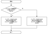
- FIG. 11 shows an example of the operation according to embodiment #2.
- the UE determines whether the condition for omitting the bitmap is met. If the condition for omitting the bitmap is met (S210: Y), in S220, the UE does not report the bitmap indicating the position of the NZCs for the Doppler CSI. If the condition for omitting the bitmap is not met (S210: N), in S230, the UE reports the bitmap indicating the position of the NZCs for the Doppler CSI.
- the bitmap indicating the location of the NZCs for Doppler CSI may follow at least one of the following options:
- This option may be applied in cases where all DD basis vectors and reported numbers of NZCs across multiple layers are reported in CSI Part 1. If all NZCs need to be reported, there is no need to report the bitmap as it will show all 1's.
- the condition v ⁇ 1/2/3/4 may relate to the maximum allowable number of NZCs for rank v.
- the maximum number of reported NZCs may be 2LMvQ.
- This option may be applied in cases where the reported number of NZCs across multiple layers per DD basis vector is reported in CSI Part 1.
- This option may be applied in cases where the reported number of NZCs per layer across all DD basis vectors is reported in CSI Part 1.
- This option may be applied in cases where the reported number of NZCs per layer per DD basis vector is reported in CSI Part 1.
- L may be the number of SD basis vectors selected/reported for a certain DD basis vector.
- UE capability may be introduced indicating support for option 1/2 for Doppler CSI based on at least one of enhanced type 2 CSI (Rel. 16) and additional enhanced type 2 PS CSI (Rel. 17).
- the UE can appropriately determine whether to report a bitmap indicating the locations of NZCs for Doppler CSI.
- any information may be notified to the UE (from a network (NW) (e.g., a base station (BS))) (in other words, any information is received from the BS by the UE) using physical layer signaling (e.g., DCI), higher layer signaling (e.g., RRC signaling, MAC CE), a specific signal/channel (e.g., PDCCH, PDSCH, reference signal), or a combination thereof.
- NW network
- BS base station
- the MAC CE may be identified by including a new Logical Channel ID (LCID) in the MAC subheader that is not specified in existing standards.
- LCID Logical Channel ID
- the notification When the notification is made by a DCI, the notification may be made by a specific field of the DCI, a Radio Network Temporary Identifier (RNTI) used to scramble Cyclic Redundancy Check (CRC) bits assigned to the DCI, the format of the DCI, etc.
- RNTI Radio Network Temporary Identifier
- CRC Cyclic Redundancy Check
- notification of any information to the UE in the above-mentioned embodiments may be performed periodically, semi-persistently, or aperiodically.
- notification of any information from the UE (to the NW) may be performed using physical layer signaling (e.g., UCI), higher layer signaling (e.g., RRC signaling, MAC CE), a specific signal/channel (e.g., PUCCH, PUSCH, PRACH, reference signal), or a combination thereof.
- physical layer signaling e.g., UCI
- higher layer signaling e.g., RRC signaling, MAC CE
- a specific signal/channel e.g., PUCCH, PUSCH, PRACH, reference signal
- the MAC CE may be identified by including a new LCID in the MAC subheader that is not specified in existing standards.
- the notification may be transmitted using PUCCH or PUSCH.
- notification of any information from the UE may be performed periodically, semi-persistently, or aperiodically.
- At least one of the above-mentioned embodiments may be applied when a specific condition is satisfied, which may be specified in a standard or may be notified to a UE/BS using higher layer signaling/physical layer signaling.
- At least one of the above-described embodiments may be applied only to UEs that have reported or support a particular UE capability.
- the specific UE capabilities may indicate at least one of the following: - Supporting specific processing/operations/control/information for at least one of the above embodiments.
- the above-mentioned specific UE capabilities may be capabilities that are applied across all frequencies (commonly regardless of frequency), capabilities per frequency (e.g., one or a combination of a cell, band, band combination, BWP, component carrier, etc.), capabilities per frequency range (e.g., Frequency Range 1 (FR1), FR2, FR3, FR4, FR5, FR2-1, FR2-2), capabilities per subcarrier spacing (SubCarrier Spacing (SCS)), or capabilities per Feature Set (FS) or Feature Set Per Component-carrier (FSPC).
- FR1 Frequency Range 1
- FR2 FR2, FR3, FR4, FR5, FR2-1, FR2-2
- SCS subcarrier Spacing
- FS Feature Set
- FSPC Feature Set Per Component-carrier
- the specific UE capabilities may be capabilities that are applied across all duplexing methods (commonly regardless of the duplexing method), or may be capabilities for each duplexing method (e.g., Time Division Duplex (TDD) and Frequency Division Duplex (FDD)).
- TDD Time Division Duplex
- FDD Frequency Division Duplex
- At least one of the above-mentioned embodiments may be applied when the UE configures/activates/triggers specific information related to the above-mentioned embodiments (or performs the operations of the above-mentioned embodiments) by higher layer signaling/physical layer signaling.
- the specific information may be information indicating that the operations of the above-mentioned embodiments are enabled, any RRC parameters for a specific release (e.g., Rel. 18/19), etc.
- the UE may, for example, apply Rel. 15/16 operations.
- [Appendix 1] A receiver for receiving a configuration of coherent joint transmit CSI; and a control unit that determines whether to report a bitmap indicating positions of non-zero coefficients for the coherent joint transmit CSI based on the setting.
- Appendix 2 The terminal according to claim 1, wherein the control unit determines whether to report the bitmap based on conditions of a rank number and a reported number of non-zero coefficients.
- Appendix 3 The terminal according to Supplementary Note 1 or Supplementary Note 2, wherein the number of reports is a number of reports of non-zero coefficients across all transmission and reception points and multiple layers for the coherent joint transmission CSI.
- [Appendix 4] The terminal according to any one of Supplementary Note 1 to Supplementary Note 3, wherein the number of reports is a number of reports of non-zero coefficients across one transmission/reception point and multiple layers for the coherent joint transmission CSI.
- [Appendix 1] A receiver for receiving a Doppler CSI setting; A control unit that determines whether to report a bitmap indicating positions of non-zero coefficients for the Doppler CSI based on the setting.
- [Appendix 2] The terminal according to claim 1, wherein the control unit determines whether to report the bitmap based on conditions of a rank number and a reported number of non-zero coefficients.
- [Appendix 3] The terminal according to claim 1 or 2, wherein the number of reports is the number of reports of all Doppler domain basis vectors and non-zero coefficients across multiple layers.
- [Appendix 4] The terminal according to any one of Supplementary Note 1 to Supplementary Note 3, wherein the number of reports is a number of reports of one Doppler domain basis vector and non-zero coefficients across multiple layers.
- Wired communication system A configuration of a wireless communication system according to an embodiment of the present disclosure will be described below.
- communication is performed using any one of the wireless communication methods according to the above embodiments of the present disclosure or a combination of these.
- FIG. 12 is a diagram showing an example of a schematic configuration of a wireless communication system according to an embodiment.
- the wireless communication system 1 (which may simply be referred to as system 1) may be a system that realizes communication using Long Term Evolution (LTE) specified by the Third Generation Partnership Project (3GPP), 5th generation mobile communication system New Radio (5G NR), or the like.
- LTE Long Term Evolution
- 3GPP Third Generation Partnership Project
- 5G NR 5th generation mobile communication system New Radio
- the wireless communication system 1 may also support dual connectivity between multiple Radio Access Technologies (RATs) (Multi-RAT Dual Connectivity (MR-DC)).
- MR-DC may include dual connectivity between LTE (Evolved Universal Terrestrial Radio Access (E-UTRA)) and NR (E-UTRA-NR Dual Connectivity (EN-DC)), dual connectivity between NR and LTE (NR-E-UTRA Dual Connectivity (NE-DC)), etc.
- RATs Radio Access Technologies
- MR-DC may include dual connectivity between LTE (Evolved Universal Terrestrial Radio Access (E-UTRA)) and NR (E-UTRA-NR Dual Connectivity (EN-DC)), dual connectivity between NR and LTE (NR-E-UTRA Dual Connectivity (NE-DC)), etc.
- E-UTRA Evolved Universal Terrestrial Radio Access
- EN-DC E-UTRA-NR Dual Connectivity
- NE-DC NR-E-UTRA Dual Connectivity
- the LTE (E-UTRA) base station (eNB) is the master node (MN), and the NR base station (gNB) is the secondary node (SN).
- the NR base station (gNB) is the MN, and the LTE (E-UTRA) base station (eNB) is the SN.
- the wireless communication system 1 may support dual connectivity between multiple base stations within the same RAT (e.g., dual connectivity in which both the MN and SN are NR base stations (gNBs) (NR-NR Dual Connectivity (NN-DC))).
- dual connectivity in which both the MN and SN are NR base stations (gNBs) (NR-NR Dual Connectivity (NN-DC))).
- gNBs NR base stations
- N-DC Dual Connectivity
- the wireless communication system 1 may include a base station 11 that forms a macrocell C1 with a relatively wide coverage, and base stations 12 (12a-12c) that are arranged within the macrocell C1 and form a small cell C2 that is narrower than the macrocell C1.
- a user terminal 20 may be located within at least one of the cells. The arrangement and number of each cell and user terminal 20 are not limited to the embodiment shown in the figure. Hereinafter, when there is no need to distinguish between the base stations 11 and 12, they will be collectively referred to as base station 10.
- the user terminal 20 may be connected to at least one of the multiple base stations 10.
- the user terminal 20 may utilize at least one of carrier aggregation (CA) using multiple component carriers (CC) and dual connectivity (DC).
- CA carrier aggregation
- CC component carriers
- DC dual connectivity
- Each CC may be included in at least one of a first frequency band (Frequency Range 1 (FR1)) and a second frequency band (Frequency Range 2 (FR2)).
- Macro cell C1 may be included in FR1
- small cell C2 may be included in FR2.
- FR1 may be a frequency band below 6 GHz (sub-6 GHz)
- FR2 may be a frequency band above 24 GHz (above-24 GHz). Note that the frequency bands and definitions of FR1 and FR2 are not limited to these, and for example, FR1 may correspond to a higher frequency band than FR2.
- the user terminal 20 may communicate using at least one of Time Division Duplex (TDD) and Frequency Division Duplex (FDD) in each CC.
- TDD Time Division Duplex
- FDD Frequency Division Duplex
- the multiple base stations 10 may be connected by wire (e.g., optical fiber conforming to the Common Public Radio Interface (CPRI), X2 interface, etc.) or wirelessly (e.g., NR communication).
- wire e.g., optical fiber conforming to the Common Public Radio Interface (CPRI), X2 interface, etc.
- NR communication e.g., NR communication
- base station 11 which corresponds to the upper station
- IAB Integrated Access Backhaul
- base station 12 which corresponds to a relay station
- the base station 10 may be connected to the core network 30 directly or via another base station 10.
- the core network 30 may include at least one of, for example, an Evolved Packet Core (EPC), a 5G Core Network (5GCN), a Next Generation Core (NGC), etc.
- EPC Evolved Packet Core
- 5GCN 5G Core Network
- NGC Next Generation Core
- the core network 30 may include network functions (Network Functions (NF)) such as, for example, a User Plane Function (UPF), an Access and Mobility management Function (AMF), a Session Management Function (SMF), a Unified Data Management (UDM), an Application Function (AF), a Data Network (DN), a Location Management Function (LMF), and Operation, Administration and Maintenance (Management) (OAM).
- NF Network Functions
- UPF User Plane Function
- AMF Access and Mobility management Function
- SMF Session Management Function
- UDM Unified Data Management
- AF Application Function
- DN Data Network
- LMF Location Management Function
- OAM Operation, Administration and Maintenance
- the user terminal 20 may be a terminal that supports at least one of the communication methods such as LTE, LTE-A, and 5G.
- a wireless access method based on Orthogonal Frequency Division Multiplexing may be used.
- OFDM Orthogonal Frequency Division Multiplexing
- CP-OFDM Cyclic Prefix OFDM
- DFT-s-OFDM Discrete Fourier Transform Spread OFDM
- OFDMA Orthogonal Frequency Division Multiple Access
- SC-FDMA Single Carrier Frequency Division Multiple Access
- the radio access method may also be called a waveform.
- other radio access methods e.g., other single-carrier transmission methods, other multi-carrier transmission methods
- a downlink shared channel (Physical Downlink Shared Channel (PDSCH)) shared by each user terminal 20, a broadcast channel (Physical Broadcast Channel (PBCH)), a downlink control channel (Physical Downlink Control Channel (PDCCH)), etc. may be used as the downlink channel.
- PDSCH Physical Downlink Shared Channel
- PBCH Physical Broadcast Channel
- PDCCH Physical Downlink Control Channel
- an uplink shared channel (Physical Uplink Shared Channel (PUSCH)) shared by each user terminal 20, an uplink control channel (Physical Uplink Control Channel (PUCCH)), a random access channel (Physical Random Access Channel (PRACH)), etc. may be used as an uplink channel.
- PUSCH Physical Uplink Shared Channel
- PUCCH Physical Uplink Control Channel
- PRACH Physical Random Access Channel
- SIB System Information Block
- PDSCH User data, upper layer control information, System Information Block (SIB), etc.
- SIB System Information Block
- PUSCH User data, upper layer control information, etc.
- MIB Master Information Block
- PBCH Physical Broadcast Channel
- Lower layer control information may be transmitted by the PDCCH.
- the lower layer control information may include, for example, downlink control information (Downlink Control Information (DCI)) including scheduling information for at least one of the PDSCH and the PUSCH.
- DCI Downlink Control Information
- the DCI for scheduling the PDSCH may be called a DL assignment or DL DCI
- the DCI for scheduling the PUSCH may be called a UL grant or UL DCI.
- the PDSCH may be interpreted as DL data
- the PUSCH may be interpreted as UL data.
- a control resource set (COntrol REsource SET (CORESET)) and a search space may be used to detect the PDCCH.
- the CORESET corresponds to the resources to search for DCI.
- the search space corresponds to the search region and search method of PDCCH candidates.
- One CORESET may be associated with one or multiple search spaces. The UE may monitor the CORESET associated with a search space based on the search space configuration.
- a search space may correspond to PDCCH candidates corresponding to one or more aggregation levels.
- One or more search spaces may be referred to as a search space set. Note that the terms “search space,” “search space set,” “search space setting,” “search space set setting,” “CORESET,” “CORESET setting,” etc. in this disclosure may be read as interchangeable.
- the PUCCH may transmit uplink control information (UCI) including at least one of channel state information (CSI), delivery confirmation information (which may be called, for example, Hybrid Automatic Repeat reQuest ACKnowledgement (HARQ-ACK), ACK/NACK, etc.), and a scheduling request (SR).
- UCI uplink control information
- CSI channel state information
- HARQ-ACK Hybrid Automatic Repeat reQuest ACKnowledgement
- ACK/NACK ACK/NACK
- SR scheduling request
- the PRACH may transmit a random access preamble for establishing a connection with a cell.
- downlink, uplink, etc. may be expressed without adding "link.”
- various channels may be expressed without adding "Physical” to the beginning.
- a synchronization signal (SS), a downlink reference signal (DL-RS), etc. may be transmitted.
- a cell-specific reference signal (CRS), a channel state information reference signal (CSI-RS), a demodulation reference signal (DMRS), a positioning reference signal (PRS), a phase tracking reference signal (PTRS), etc. may be transmitted.
- the synchronization signal may be, for example, at least one of a Primary Synchronization Signal (PSS) and a Secondary Synchronization Signal (SSS).
- a signal block including an SS (PSS, SSS) and a PBCH (and a DMRS for PBCH) may be called an SS/PBCH block, an SS Block (SSB), etc.
- the SS, SSB, etc. may also be called a reference signal.
- a measurement reference signal Sounding Reference Signal (SRS)
- a demodulation reference signal DMRS
- UL-RS uplink reference signal
- DMRS may also be called a user equipment-specific reference signal (UE-specific Reference Signal).
- the base station 13 is a diagram showing an example of a configuration of a base station according to an embodiment.
- the base station 10 includes a control unit 110, a transceiver unit 120, a transceiver antenna 130, and a transmission line interface 140. Note that one or more of each of the control unit 110, the transceiver unit 120, the transceiver antenna 130, and the transmission line interface 140 may be provided.
- this example mainly shows the functional blocks of the characteristic parts of this embodiment, and the base station 10 may also be assumed to have other functional blocks necessary for wireless communication. Some of the processing of each part described below may be omitted.
- the control unit 110 controls the entire base station 10.
- the control unit 110 can be configured from a controller, a control circuit, etc., which are described based on a common understanding in the technical field to which this disclosure pertains.
- the control unit 110 may control signal generation, scheduling (e.g., resource allocation, mapping), etc.
- the control unit 110 may control transmission and reception using the transceiver unit 120, the transceiver antenna 130, and the transmission path interface 140, measurement, etc.
- the control unit 110 may generate data, control information, sequences, etc. to be transmitted as signals, and transfer them to the transceiver unit 120.
- the control unit 110 may perform call processing of communication channels (setting, release, etc.), status management of the base station 10, management of radio resources, etc.
- the transceiver unit 120 may include a baseband unit 121, a radio frequency (RF) unit 122, and a measurement unit 123.
- the baseband unit 121 may include a transmission processing unit 1211 and a reception processing unit 1212.
- the transceiver unit 120 may be composed of a transmitter/receiver, an RF circuit, a baseband circuit, a filter, a phase shifter, a measurement circuit, a transceiver circuit, etc., which are described based on a common understanding in the technical field to which the present disclosure relates.
- the transceiver unit 120 may be configured as an integrated transceiver unit, or may be composed of a transmission unit and a reception unit.
- the transmission unit may be composed of a transmission processing unit 1211 and an RF unit 122.
- the reception unit may be composed of a reception processing unit 1212, an RF unit 122, and a measurement unit 123.
- the transmitting/receiving antenna 130 can be configured as an antenna described based on common understanding in the technical field to which this disclosure pertains, such as an array antenna.
- the transceiver 120 may transmit the above-mentioned downlink channel, synchronization signal, downlink reference signal, etc.
- the transceiver 120 may receive the above-mentioned uplink channel, uplink reference signal, etc.
- the transceiver 120 may form at least one of the transmit beam and the receive beam using digital beamforming (e.g., precoding), analog beamforming (e.g., phase rotation), etc.
- digital beamforming e.g., precoding
- analog beamforming e.g., phase rotation
- the transceiver 120 may perform Packet Data Convergence Protocol (PDCP) layer processing, Radio Link Control (RLC) layer processing (e.g., RLC retransmission control), Medium Access Control (MAC) layer processing (e.g., HARQ retransmission control), etc., on data and control information obtained from the control unit 110, and generate a bit string to be transmitted.
- PDCP Packet Data Convergence Protocol
- RLC Radio Link Control
- MAC Medium Access Control
- HARQ retransmission control HARQ retransmission control
- the transceiver 120 may perform transmission processing such as channel coding (which may include error correction coding), modulation, mapping, filtering, Discrete Fourier Transform (DFT) processing (if necessary), Inverse Fast Fourier Transform (IFFT) processing, precoding, and digital-to-analog conversion on the bit string to be transmitted, and output a baseband signal.
- transmission processing such as channel coding (which may include error correction coding), modulation, mapping, filtering, Discrete Fourier Transform (DFT) processing (if necessary), Inverse Fast Fourier Transform (IFFT) processing, precoding, and digital-to-analog conversion on the bit string to be transmitted, and output a baseband signal.
- channel coding which may include error correction coding
- DFT Discrete Fourier Transform
- IFFT Inverse Fast Fourier Transform
- the transceiver unit 120 may perform modulation, filtering, amplification, etc., on the baseband signal to a radio frequency band, and transmit the radio frequency band signal via the transceiver antenna 130.
- the transceiver unit 120 may perform amplification, filtering, demodulation to a baseband signal, etc. on the radio frequency band signal received by the transceiver antenna 130.
- the transceiver 120 may apply reception processing such as analog-to-digital conversion, Fast Fourier Transform (FFT) processing, Inverse Discrete Fourier Transform (IDFT) processing (if necessary), filtering, demapping, demodulation, decoding (which may include error correction decoding), MAC layer processing, RLC layer processing, and PDCP layer processing to the acquired baseband signal, and acquire user data, etc.
- reception processing such as analog-to-digital conversion, Fast Fourier Transform (FFT) processing, Inverse Discrete Fourier Transform (IDFT) processing (if necessary), filtering, demapping, demodulation, decoding (which may include error correction decoding), MAC layer processing, RLC layer processing, and PDCP layer processing to the acquired baseband signal, and acquire user data, etc.
- FFT Fast Fourier Transform
- IDFT Inverse Discrete Fourier Transform
- the transceiver 120 may perform measurements on the received signal.
- the measurement unit 123 may perform Radio Resource Management (RRM) measurements, Channel State Information (CSI) measurements, etc. based on the received signal.
- the measurement unit 123 may measure received power (e.g., Reference Signal Received Power (RSRP)), received quality (e.g., Reference Signal Received Quality (RSRQ), Signal to Interference plus Noise Ratio (SINR), Signal to Noise Ratio (SNR)), signal strength (e.g., Received Signal Strength Indicator (RSSI)), propagation path information (e.g., CSI), etc.
- RSRP Reference Signal Received Power
- RSSI Received Signal Strength Indicator
- the measurement results may be output to the control unit 110.
- the transmission path interface 140 may transmit and receive signals (backhaul signaling) between devices included in the core network 30 (e.g., network nodes providing NF), other base stations 10, etc., and may acquire and transmit user data (user plane data), control plane data, etc. for the user terminal 20.
- devices included in the core network 30 e.g., network nodes providing NF
- other base stations 10, etc. may acquire and transmit user data (user plane data), control plane data, etc. for the user terminal 20.
- the transmitter and receiver of the base station 10 in this disclosure may be configured with at least one of the transmitter/receiver 120, the transmitter/receiver antenna 130, and the transmission path interface 140.
- the transceiver 120 may transmit a channel state information (CSI) report configuration including one or more parameters indicating at least one of a rank indicator constraint and a codebook subset constraint.
- the controller 110 may apply the one or more parameters to the coherent joint transmission CSI and control the reception of the CSI report.
- CSI channel state information
- the transceiver unit 120 may transmit a setting for the coherent joint transmit CSI.
- the control unit 110 may determine whether to receive a bitmap indicating the positions of non-zero coefficients for the coherent joint transmit CSI based on the setting.
- the transceiver unit 120 may transmit the settings for the Doppler CSI.
- the control unit 110 may determine whether to receive a bitmap indicating the positions of the non-zero coefficients for the Doppler CSI based on the settings.
- the user terminal 14 is a diagram showing an example of the configuration of a user terminal according to an embodiment.
- the user terminal 20 includes a control unit 210, a transceiver unit 220, and a transceiver antenna 230. Note that the control unit 210, the transceiver unit 220, and the transceiver antenna 230 may each include one or more.
- this example mainly shows the functional blocks of the characteristic parts of this embodiment, and the user terminal 20 may also be assumed to have other functional blocks necessary for wireless communication. Some of the processing of each part described below may be omitted.
- the control unit 210 controls the entire user terminal 20.
- the control unit 210 can be configured from a controller, a control circuit, etc., which are described based on a common understanding in the technical field to which this disclosure pertains.
- the control unit 210 may control signal generation, mapping, etc.
- the control unit 210 may control transmission and reception using the transceiver unit 220 and the transceiver antenna 230, measurement, etc.
- the control unit 210 may generate data, control information, sequences, etc. to be transmitted as signals, and transfer them to the transceiver unit 220.
- the transceiver unit 220 may include a baseband unit 221, an RF unit 222, and a measurement unit 223.
- the baseband unit 221 may include a transmission processing unit 2211 and a reception processing unit 2212.
- the transceiver unit 220 may be composed of a transmitter/receiver, an RF circuit, a baseband circuit, a filter, a phase shifter, a measurement circuit, a transceiver circuit, etc., which are described based on a common understanding in the technical field to which the present disclosure relates.
- the transceiver unit 220 may be configured as an integrated transceiver unit, or may be composed of a transmission unit and a reception unit.
- the transmission unit may be composed of a transmission processing unit 2211 and an RF unit 222.
- the reception unit may be composed of a reception processing unit 2212, an RF unit 222, and a measurement unit 223.
- the transmitting/receiving antenna 230 can be configured as an antenna described based on common understanding in the technical field to which this disclosure pertains, such as an array antenna.
- the transceiver 220 may receive the above-mentioned downlink channel, synchronization signal, downlink reference signal, etc.
- the transceiver 220 may transmit the above-mentioned uplink channel, uplink reference signal, etc.
- the transceiver 220 may form at least one of the transmit beam and receive beam using digital beamforming (e.g., precoding), analog beamforming (e.g., phase rotation), etc.
- digital beamforming e.g., precoding
- analog beamforming e.g., phase rotation
- the transceiver 220 may perform PDCP layer processing, RLC layer processing (e.g., RLC retransmission control), MAC layer processing (e.g., HARQ retransmission control), etc. on the data and control information acquired from the controller 210, and generate a bit string to be transmitted.
- RLC layer processing e.g., RLC retransmission control
- MAC layer processing e.g., HARQ retransmission control
- the transceiver 220 may perform transmission processing such as channel coding (which may include error correction coding), modulation, mapping, filtering, DFT processing (if necessary), IFFT processing, precoding, and digital-to-analog conversion on the bit string to be transmitted, and output a baseband signal.
- transmission processing such as channel coding (which may include error correction coding), modulation, mapping, filtering, DFT processing (if necessary), IFFT processing, precoding, and digital-to-analog conversion on the bit string to be transmitted, and output a baseband signal.
- Whether or not to apply DFT processing may be based on the settings of transform precoding.
- the transceiver unit 220 transmission processing unit 2211
- the transceiver unit 220 may perform DFT processing as the above-mentioned transmission processing in order to transmit the channel using a DFT-s-OFDM waveform, and when transform precoding is not enabled, it is not necessary to perform DFT processing as the above-mentioned transmission processing.
- the transceiver unit 220 may perform modulation, filtering, amplification, etc., on the baseband signal to a radio frequency band, and transmit the radio frequency band signal via the transceiver antenna 230.
- the transceiver unit 220 may perform amplification, filtering, demodulation to a baseband signal, etc. on the radio frequency band signal received by the transceiver antenna 230.
- the transceiver 220 may apply reception processing such as analog-to-digital conversion, FFT processing, IDFT processing (if necessary), filtering, demapping, demodulation, decoding (which may include error correction decoding), MAC layer processing, RLC layer processing, and PDCP layer processing to the acquired baseband signal to acquire user data, etc.
- reception processing such as analog-to-digital conversion, FFT processing, IDFT processing (if necessary), filtering, demapping, demodulation, decoding (which may include error correction decoding), MAC layer processing, RLC layer processing, and PDCP layer processing to the acquired baseband signal to acquire user data, etc.
- the transceiver 220 may perform measurements on the received signal. For example, the measurement unit 223 may perform RRM measurements, CSI measurements, etc. based on the received signal.
- the measurement unit 223 may measure received power (e.g., RSRP), received quality (e.g., RSRQ, SINR, SNR), signal strength (e.g., RSSI), propagation path information (e.g., CSI), etc.
- the measurement results may be output to the control unit 210.
- the measurement unit 223 may derive channel measurements for CSI calculation based on channel measurement resources.
- the channel measurement resources may be, for example, non-zero power (NZP) CSI-RS resources.
- the measurement unit 223 may derive interference measurements for CSI calculation based on interference measurement resources.
- the interference measurement resources may be at least one of NZP CSI-RS resources for interference measurement, CSI-Interference Measurement (IM) resources, etc.
- CSI-IM may be called CSI-Interference Management (IM) or may be interchangeably read as Zero Power (ZP) CSI-RS.
- CSI-RS, NZP CSI-RS, ZP CSI-RS, CSI-IM, CSI-SSB, etc. may be read as interchangeable.
- the transmitting unit and receiving unit of the user terminal 20 in this disclosure may be configured by at least one of the transmitting/receiving unit 220 and the transmitting/receiving antenna 230.
- the transceiver unit 220 may receive a configuration of the coherent joint transmit CSI.
- the control unit 210 may determine whether to report a bitmap indicating the positions of the non-zero coefficients for the coherent joint transmit CSI based on the configuration.
- the control unit 210 may determine whether to report the bitmap based on the conditions of the number of ranks and the number of reported non-zero coefficients.
- the number of reports may be the number of reports of non-zero coefficients across all transmission/reception points and multiple layers for the coherent joint transmission CSI.
- the number of reports may be the number of reports of non-zero coefficients across one transmission/reception point and multiple layers for the coherent joint transmission CSI.
- the transceiver unit 220 may receive a setting for the Doppler CSI.
- the control unit 210 may determine whether to report a bitmap indicating the positions of the non-zero coefficients for the Doppler CSI based on the setting.
- the control unit 210 may determine whether to report the bitmap based on the conditions of the number of ranks and the number of reported non-zero coefficients.
- the number of reports may be the number of reports of all Doppler domain basis vectors and non-zero coefficients across multiple layers.
- the number of reports may be the number of reports of one Doppler domain basis vector and non-zero coefficients across multiple layers.
- each functional block may be realized using one device that is physically or logically coupled, or may be realized using two or more devices that are physically or logically separated and directly or indirectly connected (for example, using wires, wirelessly, etc.).
- the functional blocks may be realized by combining the one device or the multiple devices with software.
- the functions include, but are not limited to, judgement, determination, judgment, calculation, computation, processing, derivation, investigation, search, confirmation, reception, transmission, output, access, resolution, selection, election, establishment, comparison, assumption, expectation, deeming, broadcasting, notifying, communicating, forwarding, configuring, reconfiguring, allocating, mapping, and assignment.
- a functional block (component) that performs the transmission function may be called a transmitting unit, a transmitter, and the like. In either case, as mentioned above, there are no particular limitations on the method of realization.
- a base station, a user terminal, etc. in one embodiment of the present disclosure may function as a computer that performs processing of the wireless communication method of the present disclosure.
- FIG. 15 is a diagram showing an example of the hardware configuration of a base station and a user terminal according to one embodiment.
- the above-mentioned base station 10 and user terminal 20 may be physically configured as a computer device including a processor 1001, a memory 1002, a storage 1003, a communication device 1004, an input device 1005, an output device 1006, a bus 1007, etc.
- the terms apparatus, circuit, device, section, unit, etc. may be interpreted as interchangeable.
- the hardware configuration of the base station 10 and the user terminal 20 may be configured to include one or more of the devices shown in the figures, or may be configured to exclude some of the devices.
- processor 1001 may be implemented by one or more chips.
- the functions of the base station 10 and the user terminal 20 are realized, for example, by loading specific software (programs) onto hardware such as the processor 1001 and memory 1002, causing the processor 1001 to perform calculations, control communications via the communication device 1004, and control at least one of the reading and writing of data in the memory 1002 and storage 1003.
- the processor 1001 for example, runs an operating system to control the entire computer.
- the processor 1001 may be configured as a central processing unit (CPU) including an interface with peripheral devices, a control device, an arithmetic unit, registers, etc.
- CPU central processing unit
- control unit 110 210
- transmission/reception unit 120 220
- etc. may be realized by the processor 1001.
- the processor 1001 also reads out programs (program codes), software modules, data, etc. from at least one of the storage 1003 and the communication device 1004 into the memory 1002, and executes various processes according to these.
- the programs used are those that cause a computer to execute at least some of the operations described in the above embodiments.
- the control unit 110 (210) may be realized by a control program stored in the memory 1002 and running on the processor 1001, and similar implementations may be made for other functional blocks.
- Memory 1002 is a computer-readable recording medium and may be composed of at least one of, for example, Read Only Memory (ROM), Erasable Programmable ROM (EPROM), Electrically EPROM (EEPROM), Random Access Memory (RAM), and other suitable storage media. Memory 1002 may also be called a register, cache, main memory, etc. Memory 1002 can store executable programs (program codes), software modules, etc. for implementing a wireless communication method according to one embodiment of the present disclosure.
- ROM Read Only Memory
- EPROM Erasable Programmable ROM
- EEPROM Electrically EPROM
- RAM Random Access Memory
- Memory 1002 may also be called a register, cache, main memory, etc.
- Memory 1002 can store executable programs (program codes), software modules, etc. for implementing a wireless communication method according to one embodiment of the present disclosure.
- Storage 1003 is a computer-readable recording medium and may be composed of at least one of a flexible disk, a floppy disk, a magneto-optical disk (e.g., a compact disk (Compact Disc ROM (CD-ROM)), a digital versatile disk, a Blu-ray disk), a removable disk, a hard disk drive, a smart card, a flash memory device (e.g., a card, a stick, a key drive), a magnetic stripe, a database, a server, or other suitable storage medium.
- Storage 1003 may also be referred to as an auxiliary storage device.
- the communication device 1004 is hardware (transmitting/receiving device) for communicating between computers via at least one of a wired network and a wireless network, and is also called, for example, a network device, a network controller, a network card, or a communication module.
- the communication device 1004 may be configured to include a high-frequency switch, a duplexer, a filter, a frequency synthesizer, etc., to realize at least one of Frequency Division Duplex (FDD) and Time Division Duplex (TDD).
- FDD Frequency Division Duplex
- TDD Time Division Duplex
- the above-mentioned transmitting/receiving unit 120 (220), transmitting/receiving antenna 130 (230), etc. may be realized by the communication device 1004.
- the transmitting/receiving unit 120 (220) may be implemented as a transmitting unit 120a (220a) and a receiving unit 120b (220b) that are physically or logically separated.
- the input device 1005 is an input device (e.g., a keyboard, a mouse, a microphone, a switch, a button, a sensor, etc.) that accepts input from the outside.
- the output device 1006 is an output device (e.g., a display, a speaker, a Light Emitting Diode (LED) lamp, etc.) that outputs to the outside.
- the input device 1005 and the output device 1006 may be integrated into one structure (e.g., a touch panel).
- each device such as the processor 1001 and memory 1002 is connected by a bus 1007 for communicating information.
- the bus 1007 may be configured using a single bus, or may be configured using different buses between each device.
- the base station 10 and the user terminal 20 may be configured to include hardware such as a microprocessor, a digital signal processor (DSP), an application specific integrated circuit (ASIC), a programmable logic device (PLD), or a field programmable gate array (FPGA), and some or all of the functional blocks may be realized using the hardware.
- the processor 1001 may be implemented using at least one of these pieces of hardware.
- a channel, a symbol, and a signal may be read as mutually interchangeable.
- a signal may also be a message.
- a reference signal may be abbreviated as RS, and may be called a pilot, a pilot signal, or the like depending on the applied standard.
- a component carrier may also be called a cell, a frequency carrier, a carrier frequency, or the like.
- a radio frame may be composed of one or more periods (frames) in the time domain.
- Each of the one or more periods (frames) constituting a radio frame may be called a subframe.
- a subframe may be composed of one or more slots in the time domain.
- a subframe may have a fixed time length (e.g., 1 ms) that is independent of numerology.
- the numerology may be a communication parameter that is applied to at least one of the transmission and reception of a signal or channel.
- the numerology may indicate, for example, at least one of the following: SubCarrier Spacing (SCS), bandwidth, symbol length, cyclic prefix length, Transmission Time Interval (TTI), number of symbols per TTI, radio frame configuration, a specific filtering process performed by the transceiver in the frequency domain, a specific windowing process performed by the transceiver in the time domain, etc.
- SCS SubCarrier Spacing
- TTI Transmission Time Interval
- radio frame configuration a specific filtering process performed by the transceiver in the frequency domain
- a specific windowing process performed by the transceiver in the time domain etc.
- a slot may consist of one or more symbols in the time domain (such as Orthogonal Frequency Division Multiplexing (OFDM) symbols, Single Carrier Frequency Division Multiple Access (SC-FDMA) symbols, etc.).
- OFDM Orthogonal Frequency Division Multiplexing
- SC-FDMA Single Carrier Frequency Division Multiple Access
- a slot may also be a time unit based on numerology.
- a slot may include multiple minislots. Each minislot may consist of one or multiple symbols in the time domain. A minislot may also be called a subslot. A minislot may consist of fewer symbols than a slot.
- a PDSCH (or PUSCH) transmitted in a time unit larger than a minislot may be called PDSCH (PUSCH) mapping type A.
- a PDSCH (or PUSCH) transmitted using a minislot may be called PDSCH (PUSCH) mapping type B.
- a radio frame, a subframe, a slot, a minislot, and a symbol all represent time units when transmitting a signal.
- a different name may be used for a radio frame, a subframe, a slot, a minislot, and a symbol, respectively.
- the time units such as a frame, a subframe, a slot, a minislot, and a symbol in this disclosure may be read as interchangeable.
- one subframe may be called a TTI
- multiple consecutive subframes may be called a TTI
- one slot or one minislot may be called a TTI.
- at least one of the subframe and the TTI may be a subframe (1 ms) in existing LTE, a period shorter than 1 ms (e.g., 1-13 symbols), or a period longer than 1 ms.
- the unit representing the TTI may be called a slot, minislot, etc., instead of a subframe.
- TTI refers to, for example, the smallest time unit for scheduling in wireless communication.
- a base station schedules each user terminal by allocating radio resources (such as frequency bandwidth and transmission power that can be used by each user terminal) in TTI units.
- radio resources such as frequency bandwidth and transmission power that can be used by each user terminal
- the TTI may be a transmission time unit for a channel-coded data packet (transport block), a code block, a code word, etc., or may be a processing unit for scheduling, link adaptation, etc.
- the time interval e.g., the number of symbols
- the time interval in which a transport block, a code block, a code word, etc. is actually mapped may be shorter than the TTI.
- one or more TTIs may be the minimum time unit of scheduling.
- the number of slots (minislots) that constitute the minimum time unit of scheduling may be controlled.
- a TTI having a time length of 1 ms may be called a normal TTI (TTI in 3GPP Rel. 8-12), normal TTI, long TTI, normal subframe, normal subframe, long subframe, slot, etc.
- a TTI shorter than a normal TTI may be called a shortened TTI, short TTI, partial or fractional TTI, shortened subframe, short subframe, minislot, subslot, slot, etc.
- a long TTI (e.g., a normal TTI, a subframe, etc.) may be interpreted as a TTI having a time length of more than 1 ms
- a short TTI e.g., a shortened TTI, etc.
- TTI length shorter than the TTI length of a long TTI and equal to or greater than 1 ms.
- a resource block is a resource allocation unit in the time domain and frequency domain, and may include one or more consecutive subcarriers in the frequency domain.
- the number of subcarriers included in an RB may be the same regardless of numerology, and may be, for example, 12.
- the number of subcarriers included in an RB may be determined based on numerology.
- an RB may include one or more symbols in the time domain and may be one slot, one minislot, one subframe, or one TTI in length.
- One TTI, one subframe, etc. may each be composed of one or more resource blocks.
- one or more RBs may be referred to as a physical resource block (Physical RB (PRB)), a sub-carrier group (Sub-Carrier Group (SCG)), a resource element group (Resource Element Group (REG)), a PRB pair, an RB pair, etc.
- PRB Physical RB
- SCG sub-carrier Group
- REG resource element group
- PRB pair an RB pair, etc.
- a resource block may be composed of one or more resource elements (REs).
- REs resource elements
- one RE may be a radio resource area of one subcarrier and one symbol.
- a Bandwidth Part which may also be referred to as a partial bandwidth, may represent a subset of contiguous common resource blocks (RBs) for a given numerology on a given carrier, where the common RBs may be identified by an index of the RB relative to a common reference point of the carrier.
- PRBs may be defined in a BWP and numbered within the BWP.
- the BWP may include a UL BWP (BWP for UL) and a DL BWP (BWP for DL).
- BWP UL BWP
- BWP for DL DL BWP
- One or more BWPs may be configured for a UE within one carrier.
- At least one of the configured BWPs may be active, and the UE may not expect to transmit or receive a given signal/channel outside the active BWP.
- BWP bitmap
- radio frames, subframes, slots, minislots, and symbols are merely examples.
- the number of subframes included in a radio frame, the number of slots per subframe or radio frame, the number of minislots included in a slot, the number of symbols and RBs included in a slot or minislot, the number of subcarriers included in an RB, as well as the number of symbols in a TTI, the symbol length, and the cyclic prefix (CP) length can be changed in various ways.
- the information, parameters, etc. described in this disclosure may be represented using absolute values, may be represented using relative values from a predetermined value, or may be represented using other corresponding information.
- a radio resource may be indicated by a predetermined index.
- the names used for parameters and the like in this disclosure are not limiting in any respect. Furthermore, the formulas and the like using these parameters may differ from those explicitly disclosed in this disclosure.
- the various channels (PUCCH, PDCCH, etc.) and information elements may be identified by any suitable names, and therefore the various names assigned to these various channels and information elements are not limiting in any respect.
- the information, signals, etc. described in this disclosure may be represented using any of a variety of different technologies.
- the data, instructions, commands, information, signals, bits, symbols, chips, etc. that may be referred to throughout the above description may be represented by voltages, currents, electromagnetic waves, magnetic fields or magnetic particles, optical fields or photons, or any combination thereof.
- information, signals, etc. may be output from a higher layer to a lower layer and/or from a lower layer to a higher layer.
- Information, signals, etc. may be input/output via multiple network nodes.
- Input/output information, signals, etc. may be stored in a specific location (e.g., memory) or may be managed using a management table. Input/output information, signals, etc. may be overwritten, updated, or added to. Output information, signals, etc. may be deleted. Input information, signals, etc. may be transmitted to another device.
- a specific location e.g., memory
- Input/output information, signals, etc. may be overwritten, updated, or added to.
- Output information, signals, etc. may be deleted.
- Input information, signals, etc. may be transmitted to another device.
- the notification of information is not limited to the aspects/embodiments described in this disclosure, and may be performed using other methods.
- the notification of information in this disclosure may be performed by physical layer signaling (e.g., Downlink Control Information (DCI), Uplink Control Information (UCI)), higher layer signaling (e.g., Radio Resource Control (RRC) signaling, broadcast information (Master Information Block (MIB), System Information Block (SIB)), etc.), Medium Access Control (MAC) signaling), other signals, or a combination of these.
- DCI Downlink Control Information
- UCI Uplink Control Information
- RRC Radio Resource Control
- MIB Master Information Block
- SIB System Information Block
- MAC Medium Access Control
- the physical layer signaling may be called Layer 1/Layer 2 (L1/L2) control information (L1/L2 control signal), L1 control information (L1 control signal), etc.
- the RRC signaling may be called an RRC message, for example, an RRC Connection Setup message, an RRC Connection Reconfiguration message, etc.
- the MAC signaling may be notified, for example, using a MAC Control Element (CE).
- CE MAC Control Element
- notification of specified information is not limited to explicit notification, but may be implicit (e.g., by not notifying the specified information or by notifying other information).
- the determination may be based on a value represented by a single bit (0 or 1), a Boolean value represented by true or false, or a comparison of numerical values (e.g., with a predetermined value).
- Software shall be construed broadly to mean instructions, instruction sets, code, code segments, program code, programs, subprograms, software modules, applications, software applications, software packages, routines, subroutines, objects, executable files, threads of execution, procedures, functions, etc., whether referred to as software, firmware, middleware, microcode, hardware description language, or otherwise.
- Software, instructions, information, etc. may also be transmitted and received via a transmission medium.
- a transmission medium For example, if the software is transmitted from a website, server, or other remote source using at least one of wired technologies (such as coaxial cable, fiber optic cable, twisted pair, Digital Subscriber Line (DSL)), and/or wireless technologies (such as infrared, microwave, etc.), then at least one of these wired and wireless technologies is included within the definition of a transmission medium.
- wired technologies such as coaxial cable, fiber optic cable, twisted pair, Digital Subscriber Line (DSL)
- wireless technologies such as infrared, microwave, etc.
- Network may refer to the devices included in the network (e.g., base stations).
- the antenna port may be interchangeably read as an antenna port for any signal/channel (e.g., a demodulation reference signal (DMRS) port).
- the resource may be interchangeably read as a resource for any signal/channel (e.g., a reference signal resource, an SRS resource, etc.).
- the resource may include time/frequency/code/space/power resources.
- the spatial domain transmission filter may include at least one of a spatial domain transmission filter and a spatial domain reception filter.
- the above groups may include, for example, at least one of a spatial relationship group, a Code Division Multiplexing (CDM) group, a Reference Signal (RS) group, a Control Resource Set (CORESET) group, a PUCCH group, an antenna port group (e.g., a DMRS port group), a layer group, a resource group, a beam group, an antenna group, a panel group, etc.
- CDM Code Division Multiplexing
- RS Reference Signal
- CORESET Control Resource Set
- beam SRS Resource Indicator (SRI), CORESET, CORESET pool, PDSCH, PUSCH, codeword (CW), transport block (TB), RS, etc. may be read as interchangeable.
- SRI SRS Resource Indicator
- CORESET CORESET pool
- PDSCH PUSCH
- codeword CW
- TB transport block
- RS etc.
- TCI state downlink TCI state
- DL TCI state downlink TCI state
- UL TCI state uplink TCI state
- unified TCI state common TCI state
- joint TCI state etc.
- QCL QCL
- QCL assumptions QCL relationship
- QCL type information QCL property/properties
- specific QCL type e.g., Type A, Type D
- specific QCL type e.g., Type A, Type D
- index identifier
- indicator indication, resource ID, etc.
- sequence list, set, group, cluster, subset, etc.
- TCI state ID the spatial relationship information identifier
- TCI state ID the spatial relationship information
- TCI state the spatial relationship information
- TCI state the spatial relationship information
- TCI state the spatial relationship information
- Base Station may also be referred to by terms such as macrocell, small cell, femtocell, picocell, etc.
- a base station can accommodate one or more (e.g., three) cells.
- a base station accommodates multiple cells, the entire coverage area of the base station can be divided into multiple smaller areas, and each smaller area can also provide communication services by a base station subsystem (e.g., a small base station for indoor use (Remote Radio Head (RRH))).
- RRH Remote Radio Head
- the term "cell” or “sector” refers to a part or the entire coverage area of at least one of the base station and base station subsystems that provide communication services in this coverage.
- a base station transmitting information to a terminal may be interpreted as the base station instructing the terminal to control/operate based on the information.
- MS Mobile Station
- UE User Equipment
- a mobile station may also be referred to as a subscriber station, mobile unit, subscriber unit, wireless unit, remote unit, mobile device, wireless device, wireless communication device, remote device, mobile subscriber station, access terminal, mobile terminal, wireless terminal, remote terminal, handset, user agent, mobile client, client, or some other suitable terminology.
- At least one of the base station and the mobile station may be called a transmitting device, a receiving device, a wireless communication device, etc.
- at least one of the base station and the mobile station may be a device mounted on a moving object, the moving object itself, etc.
- the moving body in question refers to an object that can move, and the moving speed is arbitrary, and of course includes the case where the moving body is stationary.
- the moving body in question includes, but is not limited to, vehicles, transport vehicles, automobiles, motorcycles, bicycles, connected cars, excavators, bulldozers, wheel loaders, dump trucks, forklifts, trains, buses, handcarts, rickshaws, ships and other watercraft, airplanes, rockets, artificial satellites, drones, multicopters, quadcopters, balloons, and objects mounted on these.
- the moving body in question may also be a moving body that moves autonomously based on an operating command.
- the moving object may be a vehicle (e.g., a car, an airplane, etc.), an unmanned moving object (e.g., a drone, an autonomous vehicle, etc.), or a robot (manned or unmanned).
- a vehicle e.g., a car, an airplane, etc.
- an unmanned moving object e.g., a drone, an autonomous vehicle, etc.
- a robot manned or unmanned
- at least one of the base station and the mobile station may also include devices that do not necessarily move during communication operations.
- at least one of the base station and the mobile station may be an Internet of Things (IoT) device such as a sensor.
- IoT Internet of Things
- FIG. 16 is a diagram showing an example of a vehicle according to an embodiment.
- the vehicle 40 includes a drive unit 41, a steering unit 42, an accelerator pedal 43, a brake pedal 44, a shift lever 45, left and right front wheels 46, left and right rear wheels 47, an axle 48, an electronic control unit 49, various sensors (including a current sensor 50, a rotation speed sensor 51, an air pressure sensor 52, a vehicle speed sensor 53, an acceleration sensor 54, an accelerator pedal sensor 55, a brake pedal sensor 56, a shift lever sensor 57, and an object detection sensor 58), an information service unit 59, and a communication module 60.
- various sensors including a current sensor 50, a rotation speed sensor 51, an air pressure sensor 52, a vehicle speed sensor 53, an acceleration sensor 54, an accelerator pedal sensor 55, a brake pedal sensor 56, a shift lever sensor 57, and an object detection sensor 58
- an information service unit 59 including a communication module 60.
- the drive unit 41 is composed of at least one of an engine, a motor, and a hybrid of an engine and a motor, for example.
- the steering unit 42 includes at least a steering wheel (also called a handlebar), and is configured to steer at least one of the front wheels 46 and the rear wheels 47 based on the operation of the steering wheel operated by the user.
- the electronic control unit 49 is composed of a microprocessor 61, memory (ROM, RAM) 62, and a communication port (e.g., an Input/Output (IO) port) 63. Signals are input to the electronic control unit 49 from various sensors 50-58 provided in the vehicle.
- the electronic control unit 49 may also be called an Electronic Control Unit (ECU).
- ECU Electronic Control Unit
- Signals from the various sensors 50-58 include a current signal from a current sensor 50 that senses the motor current, a rotation speed signal of the front wheels 46/rear wheels 47 acquired by a rotation speed sensor 51, an air pressure signal of the front wheels 46/rear wheels 47 acquired by an air pressure sensor 52, a vehicle speed signal acquired by a vehicle speed sensor 53, an acceleration signal acquired by an acceleration sensor 54, a depression amount signal of the accelerator pedal 43 acquired by an accelerator pedal sensor 55, a depression amount signal of the brake pedal 44 acquired by a brake pedal sensor 56, an operation signal of the shift lever 45 acquired by a shift lever sensor 57, and a detection signal for detecting obstacles, vehicles, pedestrians, etc. acquired by an object detection sensor 58.
- the information service unit 59 is composed of various devices, such as a car navigation system, audio system, speakers, displays, televisions, and radios, for providing (outputting) various information such as driving information, traffic information, and entertainment information, and one or more ECUs that control these devices.
- the information service unit 59 uses information acquired from external devices via the communication module 60, etc., to provide various information/services (e.g., multimedia information/multimedia services) to the occupants of the vehicle 40.
- various information/services e.g., multimedia information/multimedia services
- the information service unit 59 may include input devices (e.g., a keyboard, a mouse, a microphone, a switch, a button, a sensor, a touch panel, etc.) that accept input from the outside, and may also include output devices (e.g., a display, a speaker, an LED lamp, a touch panel, etc.) that perform output to the outside.
- input devices e.g., a keyboard, a mouse, a microphone, a switch, a button, a sensor, a touch panel, etc.
- output devices e.g., a display, a speaker, an LED lamp, a touch panel, etc.
- the driving assistance system unit 64 is composed of various devices that provide functions for preventing accidents and reducing the driver's driving load, such as a millimeter wave radar, a Light Detection and Ranging (LiDAR), a camera, a positioning locator (e.g., a Global Navigation Satellite System (GNSS)), map information (e.g., a High Definition (HD) map, an Autonomous Vehicle (AV) map, etc.), a gyro system (e.g., an Inertial Measurement Unit (IMU), an Inertial Navigation System (INS), etc.), an Artificial Intelligence (AI) chip, and an AI processor, and one or more ECUs that control these devices.
- the driving assistance system unit 64 also transmits and receives various information via the communication module 60 to realize a driving assistance function or an autonomous driving function.
- the communication module 60 can communicate with the microprocessor 61 and components of the vehicle 40 via the communication port 63.
- the communication module 60 transmits and receives data (information) via the communication port 63 between the drive unit 41, steering unit 42, accelerator pedal 43, brake pedal 44, shift lever 45, left and right front wheels 46, left and right rear wheels 47, axles 48, the microprocessor 61 and memory (ROM, RAM) 62 in the electronic control unit 49, and the various sensors 50-58 that are provided on the vehicle 40.
- the communication module 60 is a communication device that can be controlled by the microprocessor 61 of the electronic control unit 49 and can communicate with an external device. For example, it transmits and receives various information to and from the external device via wireless communication.
- the communication module 60 may be located either inside or outside the electronic control unit 49.
- the external device may be, for example, the above-mentioned base station 10 or user terminal 20.
- the communication module 60 may also be, for example, at least one of the above-mentioned base station 10 and user terminal 20 (it may function as at least one of the base station 10 and user terminal 20).
- the communication module 60 may transmit at least one of the signals from the various sensors 50-58 described above input to the electronic control unit 49, information obtained based on the signals, and information based on input from the outside (user) obtained via the information service unit 59 to an external device via wireless communication.
- the electronic control unit 49, the various sensors 50-58, the information service unit 59, etc. may be referred to as input units that accept input.
- the PUSCH transmitted by the communication module 60 may include information based on the above input.
- the communication module 60 receives various information (traffic information, signal information, vehicle distance information, etc.) transmitted from an external device and displays it on an information service unit 59 provided in the vehicle.
- the information service unit 59 may also be called an output unit that outputs information (for example, outputs information to a device such as a display or speaker based on the PDSCH (or data/information decoded from the PDSCH) received by the communication module 60).
- the communication module 60 also stores various information received from external devices in memory 62 that can be used by the microprocessor 61. Based on the information stored in memory 62, the microprocessor 61 may control the drive unit 41, steering unit 42, accelerator pedal 43, brake pedal 44, shift lever 45, left and right front wheels 46, left and right rear wheels 47, axles 48, various sensors 50-58, and the like provided on the vehicle 40.
- the base station in the present disclosure may be read as a user terminal.
- each aspect/embodiment of the present disclosure may be applied to a configuration in which communication between a base station and a user terminal is replaced with communication between multiple user terminals (which may be called, for example, Device-to-Device (D2D), Vehicle-to-Everything (V2X), etc.).
- the user terminal 20 may be configured to have the functions of the base station 10 described above.
- terms such as "uplink” and "downlink” may be read as terms corresponding to terminal-to-terminal communication (for example, "sidelink").
- the uplink channel, downlink channel, etc. may be read as the sidelink channel.
- the user terminal in this disclosure may be interpreted as a base station.
- the base station 10 may be configured to have the functions of the user terminal 20 described above.
- operations that are described as being performed by a base station may in some cases be performed by its upper node.
- a network that includes one or more network nodes having base stations, it is clear that various operations performed for communication with terminals may be performed by the base station, one or more network nodes other than the base station (such as, but not limited to, a Mobility Management Entity (MME) or a Serving-Gateway (S-GW)), or a combination of these.
- MME Mobility Management Entity
- S-GW Serving-Gateway
- each aspect/embodiment described in this disclosure may be used alone, in combination, or switched between depending on the implementation.
- the processing procedures, sequences, flow charts, etc. of each aspect/embodiment described in this disclosure may be rearranged as long as there is no inconsistency.
- the methods described in this disclosure present elements of various steps using an exemplary order, and are not limited to the particular order presented.
- LTE Long Term Evolution
- LTE-A LTE-Advanced
- LTE-B LTE-Beyond
- SUPER 3G IMT-Advanced
- 4th generation mobile communication system 4th generation mobile communication system
- 5G 5th generation mobile communication system
- 6G 6th generation mobile communication system
- xG x is, for example, an integer or decimal
- Future Radio Access FX
- GSM Global System for Mobile communications
- CDMA2000 Code Division Multiple Access
- UMB Ultra Mobile Broadband
- IEEE 802.11 Wi-Fi
- IEEE 802.16 WiMAX (registered trademark)
- IEEE 802.20 Ultra-WideBand (UWB), Bluetooth (registered trademark), and other appropriate wireless communication methods, as well as next-generation systems that are expanded, modified,
- the phrase “based on” does not mean “based only on,” unless expressly stated otherwise. In other words, the phrase “based on” means both “based only on” and “based at least on.”
- any reference to elements using designations such as “first,” “second,” etc., used in this disclosure does not generally limit the quantity or order of those elements. These designations may be used in this disclosure as a convenient method of distinguishing between two or more elements. Thus, a reference to a first and second element does not imply that only two elements may be employed or that the first element must precede the second element in some way.
- determining may encompass a wide variety of actions. For example, “determining” may be considered to be judging, calculating, computing, processing, deriving, investigating, looking up, search, inquiry (e.g., looking in a table, database, or other data structure), ascertaining, etc.
- Determining may also be considered to mean “determining” receiving (e.g., receiving information), transmitting (e.g., sending information), input, output, accessing (e.g., accessing data in a memory), etc.
- judgment (decision) may be considered to mean “judging (deciding)” resolving, selecting, choosing, establishing, comparing, etc.
- judgment (decision) may be considered to mean “judging (deciding)” some kind of action.
- judgment (decision) may be interpreted interchangeably with the actions described above.
- expect may be read as “be expected”.
- "expect(s)" ("" may be expressed, for example, as a that clause, a to infinitive, etc.) may be read as “be expected".
- "does not expect" may be read as "be not expected".
- "An apparatus A is not expected" may be read as "An apparatus B other than apparatus A does not expect" (for example, if apparatus A is a UE, apparatus B may be a base station).
- the "maximum transmit power" referred to in this disclosure may mean the maximum value of transmit power, may mean the nominal UE maximum transmit power, or may mean the rated UE maximum transmit power.
- connection and “coupled,” or any variation thereof, refer to any direct or indirect connection or coupling between two or more elements, and may include the presence of one or more intermediate elements between two elements that are “connected” or “coupled” to each other.
- the coupling or connection between the elements may be physical, logical, or a combination thereof. For example, "connected” may be read as "accessed.”
- a and B are different may mean “A and B are different from each other.”
- the term may also mean “A and B are each different from C.”
- Terms such as “separate” and “combined” may also be interpreted in the same way as “different.”
- timing, time, duration, time instance, any time unit e.g., slot, subslot, symbol, subframe
- period occasion, resource, etc.
Landscapes
- Engineering & Computer Science (AREA)
- Computer Networks & Wireless Communication (AREA)
- Signal Processing (AREA)
- Mobile Radio Communication Systems (AREA)
Abstract
Description
Rel.15 NRでは、端末(ユーザ端末、User Equipment(UE)等ともいう)は、参照信号(Reference Signal(RS))(又は、当該RS用のリソース)に基づいてチャネル状態情報(Channel State Information(CSI))を生成(決定、計算、推定、測定等ともいう)し、生成したCSIをネットワーク(例えば、基地局)に送信(報告、フィードバック等ともいう)する。当該CSIは、例えば、上り制御チャネル(例えば、Physical Uplink Control Channel(PUCCH))又は上り共有チャネル(例えば、Physical Uplink Shared Channel(PUSCH))を用いて基地局に送信されてもよい。
・CSI報告のタイプに関する情報(報告タイプ情報、例えば、RRC IEの「reportConfigType」)
・報告すべきCSIの一以上の量(quantity)(一以上のCSIパラメータ)に関する情報(報告量情報、例えば、RRC IEの「reportQuantity」)
・当該量(当該CSIパラメータ)の生成に用いられるRS用リソースに関する情報(リソース情報、例えば、RRC IEの「CSI-ResourceConfigId」)
・CSI報告の対象となる周波数ドメイン(frequency domain)に関する情報(周波数ドメイン情報、例えば、RRC IEの「reportFreqConfiguration」)
UEは、コードブックに関するパラメータ(コードブック設定(CodebookConfig))を、上位レイヤシグナリング(RRCシグナリング)により設定される。コードブック設定は、上位レイヤ(RRC)パラメータのCSI報告設定(CSI-ReportConfig)に含まれる。
Rel.16のCSI報告設定(CSI-ReportConfig)は、コードブック設定(CodebookConfig)の他に、チャネル測定用のCSI-RSリソース(resourcesForChannelMeasurement(CMR))、干渉測定用のCSI-RSリソース(csi-IM-ResourcesForInterference(ZP-IMR)、nzp-CSI-RS-ResourcesForInterference(NZP-IMR))等が含まれている。CSI-ReportConfigのパラメータのうち、codebookConfig-r16を除くパラメータはRel.15のCSI報告設定にも含まれる。
UEは、シングルTRP測定仮説/前提(hypotheses)に関連するX個(X=0、1、2)のCSIとNCJT測定に関連する1つのCSIを報告するように設定される。X=2の場合、2つのCSIは、異なるCMRグループのCMRを使用した2つの異なるシングルTRP測定に関連する。
UEは、NCJT及びシングルTRPについての測定仮説の中で最良の測定結果に関連する1つのCSIを報告するように設定されてもよい。
オプション1(X=0):NCJTのCSIのみの測定。
オプション1(X=1):NCJTのCSIと、シングルTRP(1つのTRP)のCSIの測定。
オプション1(X=2):NCJTのCSIと、シングルTRP(2つのTRP)のCSIの測定。
オプション2:NCJTのCSIと、シングルTRPのCSIの両方の測定。
タイプ1コードブック(Rel.15)として、基地局パネルに対し、タイプ1シングルパネルコードブックとタイプ1マルチパネルコードブックが規定されている。タイプ1シングルパネルにおいて、(N1,N2)、に対し、CSIアンテナポートアレイ(論理的設定)のアンテナモデルが規定されている。CSI-RSアンテナポート数PCSI-RSは、2N1N2である。タイプ1マルチパネルにおいて、CSI-RSアンテナポート数PCSI-RSと、(Ng,N1,N2)、に対し、CSIアンテナポートアレイ(論理的設定)のアンテナモデルが規定されている。

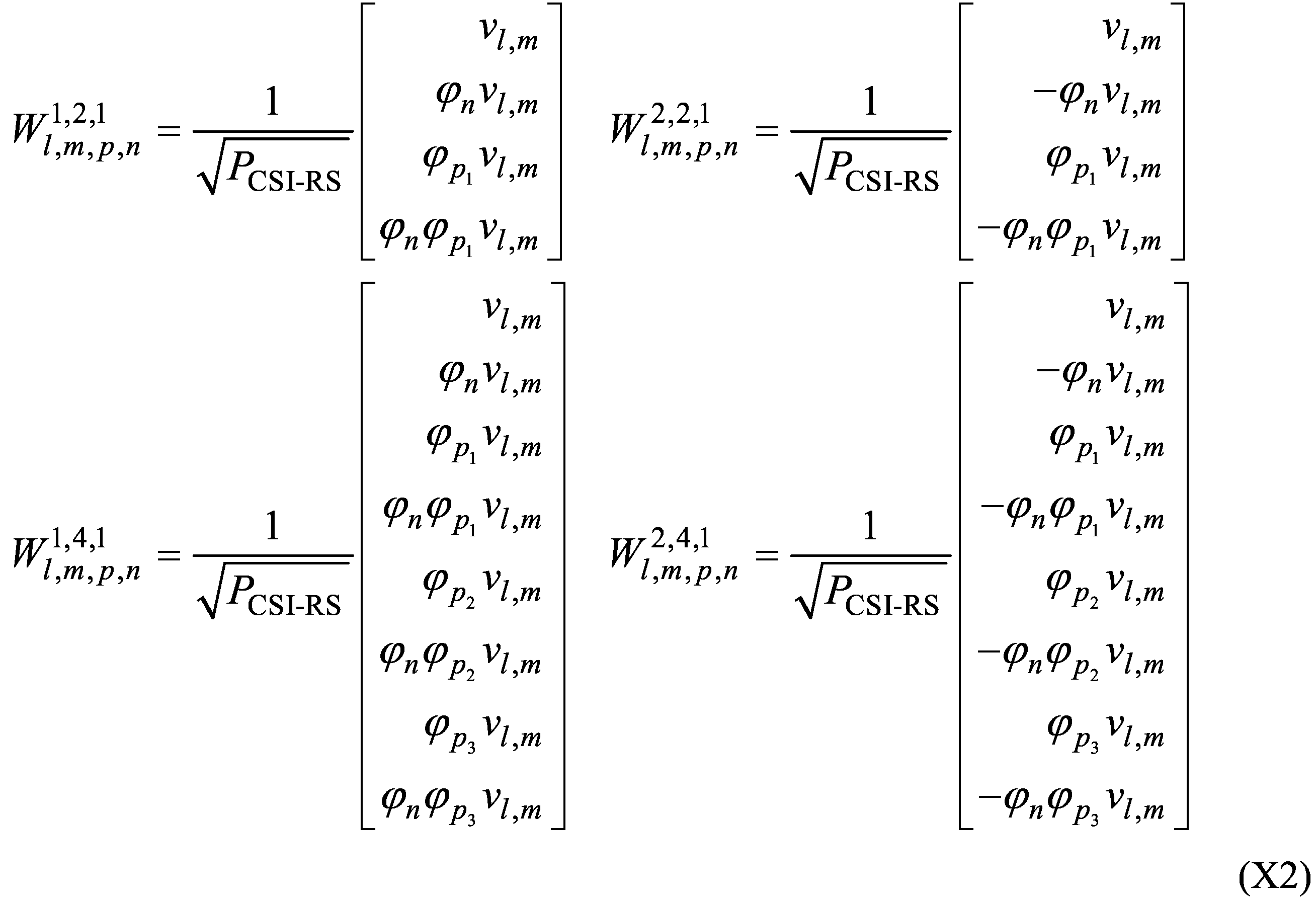
本開示において、X行Y列の行列ZをZ(X×Y)と表すことがある。
Wl(Nt×N3) = W1W2,l (X3)
Rel.16のタイプ2CSI(拡張(enhanced)タイプ2コードブック)は、周波数ドメイン(FD)圧縮によって、W2,lに関連するオーバーヘッドを低減する。Rel.16のタイプ2CSIは、ランク1及び2に加え、ランク3及び4をサポートする。
Wl = W1W~ lWf,l H (X4)
・i1,1:2次元のオーバーサンプリング因子[q1 q2]。q1∈{0,1,...,O1-1}、q2∈{0,1,...,O2-1}。
・i1,2:(SD)2D-DFT基底(ビーム)の複数インデックス。i1,2∈{0,1,...,C(N1N2,L)-1}。
・i1,5:コードブックインディケータ。選択されたDFTウィンドウの(FD)DFT基底のインデックス。i1,5∈{0,1,...,2Mv-1}。
・i1,6,l:コードブックインディケータ。l番目のレイヤに対して選択された(FD)DFT基底。N3≦19の場合、i1,6,l∈{0,1,...,C(N3-1,Mv-1)-1}。N3>19の場合、i1,6,l∈{0,1,...,C(2Mv-1,Mv-1)-1}。
・i1,7,l:l番目のレイヤに対するビットマップインディケータ。そのビットマップの内の非ゼロビットはi2,4,l及びi2,5,l内のどの係数が報告されるかを識別する。i1,7,l=[kl,0 (3) ... kl,M_v-1 (3)]、kl,f (3)=[kl,0,f (3) ... kl,M_v-1,f (3)]、kl,i,f (3)∈{0,1}。
・i1,8,l:l番目のレイヤに対する最強係数インディケータ(振幅係数インディケータ内の最大要素kl,i,f (2))。
・i2,3,l:l番目のレイヤの(両方の偏波の)係数(ワイドバンド)の振幅係数インディケータ。i2,3,l=[kl,0 (1) kl,1 (1)]。
・i2,4,l:l番目のレイヤの報告される係数(サブバンド)の振幅係数インディケータ。i2,3,l=[kl,0 (2) ... kl,M_v-1 (2)]。
・i2,5,l:l番目のレイヤの報告される係数(サブバンド)の位相係数インディケータ。i2,5,l=[cl,0,f ... cl,M_v-1,f]。
[振幅量子化]
偏波固有参照振幅は、図1のテーブル(振幅係数インディケータi2,3,l内の要素のマッピング:振幅係数インディケータ要素kl,p (1)から振幅係数pl,p (1)へのマッピング)を用いる16レベル量子化である。このテーブルによってpl (1)=[pl,0 (1) pl,1 (1)]は[kl,0 (1) kl,1 (1)]、kl,p (1)∈{0,...,15}に量子化される。他の全ての係数は、図2のテーブル(振幅係数インディケータi2,4,l内の要素のマッピング:振幅係数インディケータ要素kl,i,f (2)から振幅係数pl,i,f (2)へのマッピング)を用いる8レベル量子化である。このテーブルによってpl (2)=[pl,0 (2) ... pl,M_v-1 (2)]、pl,f (2)=[pl,0,f (2) ... pl,2L-1.f (2)]はkl,f (2)=[kl,0,f (2) ... kl,2L-1.f (2)]、kl,i,f (2)∈{0,...,7}に量子化される。
[位相量子化]
振幅係数インディケータi2,5,l内の要素(振幅係数インディケータ要素)[cl,0 ... cl,M_v-1]は、UEによって(4ビットを用いて)報告される。全ての位相係数は、16-PSKを用いて量子化される。位相整合のための量φl,i,f = exp(j2πcl,i,f/16)における位相係数は、cl,f=[cl,0,f ... cl,2L-1.f]、cl,i,fi∈{0,...,15}に量子化される。
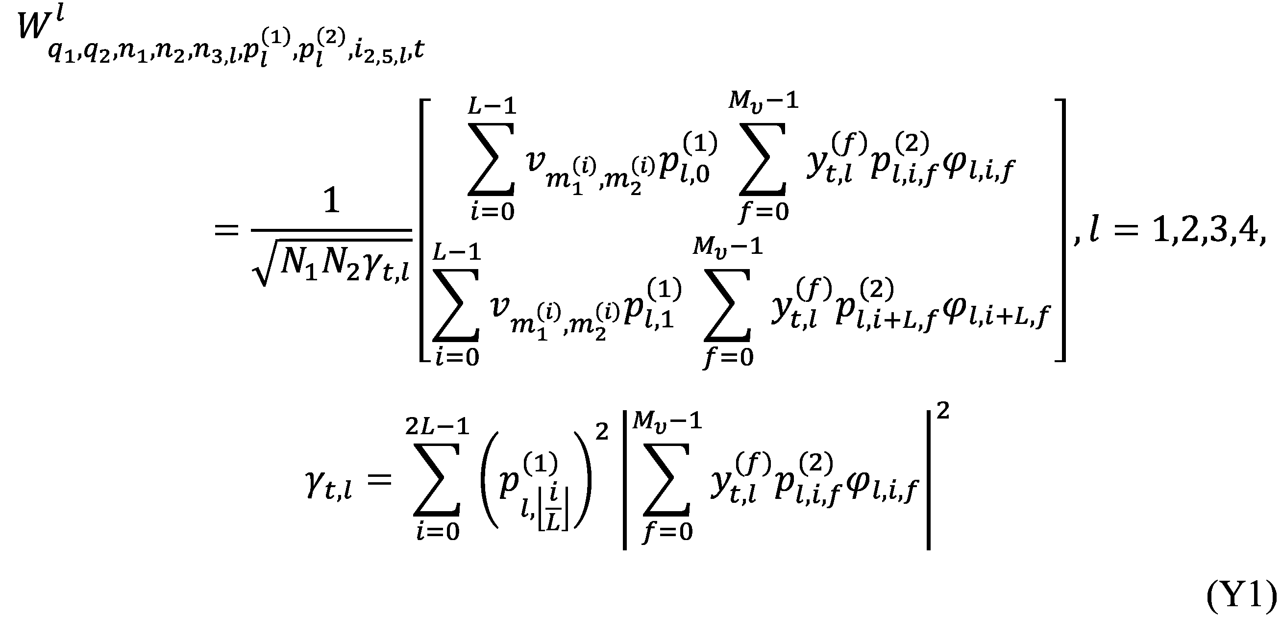
・グループ0:インデックスi1,1、i1,2、i1,8,l(l=1,...,v)
・グループ1:(報告される場合の)インデックスi1,5、(報告される場合の)インデックスi1,6,l、i1,7,lの内の最高(上位)のv2LMv-floor(KNZ/2)個の優先度要素、i2,3,l、i2,4,lの内の最高(上位)のceil(KNZ/2)-v個の優先度要素、i2,5,lの内の最高(上位)のceil(KNZ/2)-v個の優先度要素(l=1,...,v)
・グループ2:i1,7,lの内の最低(下位)のfloor(KNZ/2)個の優先度要素、i2,4,lの内の最低(下位)のfloor(KNZ/2)個の優先度要素、i2,5,lの内の最低(下位)のfloor(KNZ/2)個の優先度要素(l=1,...,v)
Rel.15のタイプ2ポート選択(port selection(PS))CSI(タイプ2PSコードブック)において、UEは、タイプ2CSIのように2D-DFTを考慮してSDビームを導出する必要がない。基地局は、SDビームのセットを考慮してビームフォームされたK個のCSI-RSポートを用いてCSI-RSを送信する。UEは、偏波ごとに最良のL(≦K)個のCSI-RSポートを選択/識別し、W1内において、それらのインデックスを報告する。Rel.15のタイプ2PS CSIは、ランク1、2をサポートする。
Wl(Nt×N3) = QW1W~ lWf,l H (Y2)
Wl(K×N3) = W1W~ lWf,l H (Y3)
PUSCH上の、タイプ1、タイプ2、拡張タイプ2、追加拡張タイプ2ポート選択のCSIフィードバックにおいて、CSI報告は、2つのパートを備える。パート1は、固定ペイロードサイズを有し、パート2内の情報ビット数の識別に用いられる。パート2よりも前に、パート1の全体が送信される。
joint transmission(JT)は、複数のポイント(例えば、TRP)から単一のUEへの同時データ送信を意味してもよい。
Rel.17において、NCJT CSI報告を適用可能なシナリオは、タイプ1シングルパネルコードブックを伴うシングルDCIベースMTRP NCJTである。NCJT CSI測定のために、単一のCSI-ReportConfig内において、1つのTRPからの各channnel measurement resource(CMR)を伴う、2つのCMRグループが設定されることができる。1つのCSI報告モードは、2つのモードから設定されることができる。
[モード1]
UEは、シングルTRP測定前提(hypothesis)に関連付けられたX個のCSIと、NCJT測定前提に関連付けられた1つのCSIと、を報告することを設定されてもよい。X=0,1,2である。X=2である場合、2つのCSIが、異なる複数のCMRグループからの複数CMRを伴う2つの異なるシングルTRP測定前提に関連付けられる。X=1,2のサポートは、オプション1をサポートするUEに対する、UEのオプショナル機能である。
[モード2]
UEは、NCJT及びシングルTRPの測定前提の内の最良の1つに関連付けられた1つのCSIを報告することを設定される。
・X=0を伴うモード1に対するワイドバンドCSIのマッピング順序。ワイドバンドCSIは、X=0を伴うモード1、すなわちNCJT CSI、のみに対してサポートされる。
・モード1及び2に対するCSIパート1のマッピング順序。
・モード1及び2に対するCSIパート2ワイドバンドのマッピング順序。
・モード1及び2に対するCSIパート2サブバンドのマッピング順序。
Rel.18において、4つまでのTRPを用いるcoherent joint transmission(CJT、mTRP CJT)をサポートすることが検討されている。4つのTRPからのデータは、コヒーレントにプリコードされ、同じ時間-周波数リソース上においてUEへ送信されてもよい。例えば、4つのTRPからのチャネルを考慮し、同じプリコーディング行列が用いられてもよい。コヒーレントは、複数の受信信号の位相の間に一定の関係があることを意味してもよい。4TRPジョイントプリコーディングを用いて、信号品質が改善され、4つのTRPの間位において干渉がなくてもよい。データは、4つのTRPの外の干渉のみを受けてもよい。
理想バックホール(ideal backhaul)と、同期と、複数TRPに跨る同じ数のアンテナポートと、を想定し、FR1及び4つまでのTRP向けのcoherent joint transmission(CJT)用のCSI取得(acquisition)が検討されている。FDD向けのCJTマルチTRPのために、Rel.16/17のタイプ2コードブックの改良が検討されている。
・4つまでのTRPの測定のためのCMR及びIMR。
・x-TRP CJTのためのTRP間(inter-TRP)CSIフィードバックを伴うTRPごとCSI。
・TRP間CSI:TRP間位相行列/TRP間振幅行列/(振幅及び位相の両方を含む)TRP間行列のための新規のフィードバック及びコードブック。
・追加で報告可能なx-TRP CJT CQI。
・各TRPのためのCMR/CSIに対する設定の制限。
・TRP間のCSI/PMI(例えば、TRP間振幅を伴う/伴わないTRP間位相)。
[オプション1]Rel.16/17タイプ2コードブックに加えて、独立のコードブック及びフィードバック。
[オプション2]Wl ~Wf,l Hを伴って/の内において伝えられるTRP間のCSI/PMIのW2。複数TRPに対して共通の/異なるFD基底。
・Rel.16/17のタイプ2コードブック及びタイプ2PSコードブックのマルチパネルへの拡張。
・タイプ2マルチパネルコードブックのための新規アンテナ設定。
TRPごと/TRPグループごとのSD/FD基底選択。それは、N個のTRP/TRPグループに跨る独立のFD基底選択を許容する。例えば、そのコードブック構造は、次式によって与えられる。ここで、Nは、TRP又はTRPグループの数である。

TRPごと/TRPグループ(ポートグループ又はリソース)ごとのSD基底選択、及び(N個のTRP/TRPグループに跨る)ジョイント/共通のFD基底選択。例えば、そのコードブック構造は、次式によって与えられる。ここで、Nは、TRP又はTRPグループの数である。

CSI報告に対する優先度ルールにおいて、CSI報告は、優先度値(priority value)PriiCSI(y,k,c,s)=2・Ncells・Ms・y+Ncells・Ms・k+Ms・c+sに関連付けられている。PUSCH上において伝達されるA-CSI報告に対してy=0である。PUSCH上において伝達されるSP-CSI報告に対してy=1である。PUCCH上において伝達されるSP-CSI報告に対してy=2である。PUCCH上において伝達されるP-CSI報告に対してy=3である。L1-RSRP又はL1-SINRを伝達するCSI報告に対してk=0である。L1-RSRP又はL1-SINRを伝達しないCSI報告に対してk=1である。cはサービングセルインデックスである。Ncellsは、設定されるサービングセルの最大数(上位レイヤパラメータmaxNrofServingCellsの値)である。sは、CSI報告設定のID(reportConfigID)である。Msは、設定されるCSI報告設定の最大数(上位レイヤパラメータmaxNrofCSI-ReportConfigurationsの値)である。第1CSI報告に対して関連付けられている優先度値が、第1CSI報告に対して関連付けられている優先度値よりも低い場合、第1CSI報告は第2CSI報告よりも優先される(第1CSI報告の優先度は第2CSI報告の優先度よりも高い)ことを意味する。
UEは、以下の能力情報を用いて、サポートされている同時CSI計算の数(同時CSI計算の最大数)NCPUを報告する。NCPUは、CSI処理ユニット(CSI processing unit、CPU)の数を暗示している。
・MIMO-ParametersPerBand内のcsi-ReportFramework内のsimultaneousCSI-ReportsPerCC。MIMO-ParametersPerBandは、あるバンドに固有のMIMO関連パラメータの伝達に用いられる。csi-ReportFrameworkは、UEがCSI報告フレームワークをサポートするかを示す。simultaneousCSI-ReportsPerCCは、UEがこの能力が提供されているバンドの1つのCC内において参照信号を同時に測定及び処理できるCSI報告の数を示す。CSI報告は、周期的、セミパーシステント、及び非周期的のCSIと、任意のレイテンシクラス及びコードブックタイプを備える。simultaneousCSI-ReportsPerCC内のCSI報告は、ビーム報告及びCSI報告を含む。
・CA-ParametersNR内のsimultaneousCSI-ReportsAllCC。simultaneousCSI-ReportsAllCCは、UEがCSI報告フレームワークをサポートするかと、UEが全てのCC(NR-DCのケースにおいてはmaster cell group(MCG)及びsecondary cell group(SCG))に跨って同時に処理できるCSI報告の数と、を示す。CSI報告は、周期的、セミパーシステント、及び非周期的のCSIと、任意のレイテンシクラス及びコードブックタイプを備える。simultaneousCSI-ReportsAllCC内のCSI報告は、ビーム報告及びCSI報告を含む。このパラメータは更に、与えられているバンドコンビネーション内の各バンドに対するMIMO-ParametersPerBand内のsimultaneousCSI-ReportsPerCC及びPhy-ParametersFRX-Diffによって制限される。
-処理1
'none'にセットされている上位レイヤパラメータreportQuantityを伴うCSI-ReportConfigと、上位レイヤパラメータtrs-Infoを伴うCSI-RS-ResourceSetと、を伴うCSI報告が設定されているケースにおいて、OCPU=0である。
-処理2(ビーム管理)
'cri-RSRP'、'ssb-Index-RSRP'、'cri-SINR'、'ssb-Index-SINR'、'cri-RSRP-Capability[Set]Index'、'ssb-Index-RSRP-Capability[Set]Index'、'cri-SINR-Capability[Set]Index'、'ssb-Index-SINR-Capability[Set]Index'、又は(上位レイヤパラメータtrs-Infoを伴うCSI-RS-ResourceSetが設定されていない場合の)'none'、にセットされている上位レイヤパラメータreportQuantityを伴うCSI-ReportConfigを伴うCSI報告において、OCPU=1である。
-処理3
'cri-RI-PMI-CQI'、'cri-RI-i1'、'cri-RI-i1-CQI'、'cri-RI-CQI'、又は'cri-RI-LI-PMI-CQI'にセットされている上位レイヤパラメータreportQuantityを伴うCSI-ReportConfigを伴うCSI報告において、OCPUは、以下の処理3-1から3-3に従う。
--処理3-1(UEがUE能力の最大限を使用できるケース)
max{μPDCCH,μCSI-RS,μUL}≦3であり、且つ、L=0個のCPUが占有されている場合にトランスポートブロック及びHARQ-ACKの少なくとも1つを伴うPUSCHその送信を伴わないCSI報告が非周期的にトリガされ、そのCSIが、ワイドバンド周波数粒度(wideband frequency-granularity)と、CRI報告を伴わない単一リソース内の4以下のCSI-RSポートと、を伴う単一CSIに対応し、codebookTypeが'typeI-SinglePanel'にセットされ、reportQuantityが'cri-RI-CQI'に設定されている場合、OCPU=NCPUである。μPDCCHはPDCCHのサブキャリア間隔(SCS)設定である。μCSI-RSはCSI-RSのSCS設定である。μULはCSI報告が送信されるUL BWPのSCS設定である。
--処理3-2(NCJT CSIのケース)
'typeI-SinglePanel'にセットされているcodebookTypeを伴うCSI-ReportConfigが設定され、それに対応するチャネル測定用のCSI-RSリソースセットが、2つのリソースグループとN個のリソースペアとを伴って設定される場合、OCPU=X・N+Mである。ここで、Xは、UE能力に従うCMRのペアによって占有されているCPUの数である。UE能力mTRP-CSI-numCPU-r17は、NCJT CSI仮定(hypotheses)のためのCMRのペアによって占有されるCPUの数を示す。KS=K1+K2個のリソースを伴うチャネル測定用NZP CSI-RSリソースセットの内の、K1個のリソースを伴うリソースグループ1とK2個のリソースを伴うリソースグループ2とに対してCRI値に関連付けられているM1個のリソースとM2個のリソースに対し、M=M1+M2である。
--処理3-3
それ以外の場合において、OCPU=KSである。KSは、チャネル測定用のCSI-RSリソースセット内のCSI-RSリソースの数である。
・P-CSI報告又はSP-CSI報告は、チャネル又は干渉の測定に対する複数のCSI-RS/CSI-IM/SSBのリソースの内、それぞれの最後のCSI-RS/CSI-IM/SSBのオケージョンが、対応するCSI参照リソース以前であるリソースの内の、最も早い1つのリソースの最初のシンボルから、その報告を伝達し設定されたPUSCH/PUCCHの最後のシンボルまで(CPU占有継続時間1)、1つ以上のCPUを占有する。そのP-CSI報告又はSP-CSI報告は、その報告をトリガするPDCCHの後のPUSCH上の最初のSP-CSI報告を除く。そのP-CSI報告又はSP-CSI報告が1つ以上のCPUを占有する時間は、CPU占有継続時間1と呼ばれてもよい。
・A-CSI報告は、そのCSI報告をトリガするPDCCHの後の最初のシンボルから、その報告を伝達し設定されたPUSCH/PUCCHの最後のシンボルまで(CPU占有継続時間2)、1つ以上のCPUを占有する。そのPDCCH受信が、2つのサーチスペースセットからの対応する2つのPDCCH候補を含む場合、CPU占有継続時間の決定のために、その2つのPDCCH候補の内の、より後の時間に終了するPDCCH候補が用いられる。そのA-CSI報告が1つ以上のCPUを占有する時間は、CPU占有継続時間2と呼ばれてもよい。
・PDCCHトリガの後のPUSCH上の最初のSP-CSI報告は、そのPDCCHの後の最初のシンボルから、その報告を伝達しスケジュールされたPUSCHの最後のシンボルまで(CPU占有継続時間3)、1つ以上のCPUを占有する。そのPDCCH受信が、2つのサーチスペースセットからの対応する2つのPDCCH候補を含む場合、CPU占有継続時間の決定のために、その2つのPDCCH候補の内の、より後の時間に終了するPDCCH候補が用いられる。そのSP-CSI報告が1つ以上のCPUを占有する時間は、CPU占有継続時間3と呼ばれてもよい。
・A-CSI-RSに対する継続時間は、その要求を含むPDCCHの終了から開始し、そのA-CSI-RSに関連付けられている報告を含みスケジュールされたPUSCHの終了において終了する。
・SP-CSI-RSに対する継続時間は、アクティベーションコマンドが適用される時間の終了から開始し、ディアクティベーションコマンドが適用される時間の終了において終了する。
・P-CSI-RSに対する継続時間は、上位レイヤシグナリングによってそのP-CSI-RSが設定されたときに開始し、そのP-CSI-RS設定がリリースされるときに終了する。
時間ドメイン相関(time-domain correlation)/ドップラードメイン情報(Doppler-domain information)を利用して、高速/中速で移動するUEのためのCSI報告を拡張/能力向上させることが検討されている。例えば、空間ドメイン基底及び周波数ドメイン基底を変更することなく、Rel.16/17のタイプ2コードブックを改良すること、トラッキング用CSI-RS(tracking RS(TRS))を介して測定される時間ドメインチャネル特性(time domain channel properties、TDCP)をUEから報告すること、が検討されている。
・CSI-RSリソースセット当たりのポート数が1つだけに制限される。各CSI-RSリソースはシングルポートを用いる。
・設定可能な周期は10ms以上である。
・TRSに対するCSI報告が想定されていない。P-TRSに対する報告設定がない。報告を設定することはできるが、報告量(reportQuantity)は、なし('none')のみにセットされる。1つのCSI-RSリソースセット当たり、最大で16個のCSI-RSリソースが用いられる。
高速/中速のためのタイプ2の改良において、NZCsの位置を示すためのビットマップに関し、以下のサポートが検討されている。
・NZCsの位置を示すためのQ個の異なる2次元ビットマップ(図9)が導入される。ここで、q(q=1,...,Q)番目の2次元ビットマップは、q番目の選択されたドップラードメイン(DD)規定ベクトルに対応する。選択されるDD基底ベクトルの数は、Qによって表される。Q個の異なる2次元ビットマップは、各レイヤにおいて、異なる選択されたDD基底ベクトルに対して、SD-FDの2次元におけるNZCsの位置が異なり得ることを暗示する。
ビットマップに関するCSI省略がサポートされるかが明らかでない。このような動作が明らかでなければ、スループット/通信品質の低下などを招くおそれがある。
各実施形態において、TRP、CMR、NZP-CSI-RSリソース、CRI、は互いに読み替えられてもよい。各実施形態において、CMRのグループ/セット、NZP-CSI-RSリソースのグループ/セット、CRIのグループ/セット、は互いに読み替えられてもよい。各実施形態において、TRPのコンビネーション/ペア/セット/グループ、CMRのコンビネーション/ペア/セット/グループ、NZP-CSI-RSリソースのコンビネーション/ペア/セット/グループ、CRIのコンビネーション/ペア/セット/グループ、は互いに読み替えられてもよい。
CJT CSIのためのCSIパート1の内容に関する規定(データ用物理レイヤ手順)が導入されてもよい。
そのインディケータの規定は、更新されない。CJT CSIのケースにおいて、そのインディケータは、全TRP(全CMR)に跨る複数レイヤに跨る非ゼロ振幅係数の総数のインディケータと解釈されてもよい。
そのインディケータの規定は、各TRP/CMRに跨る複数レイヤに跨る非ゼロ振幅係数の総数のインディケータ、と更新される。
そのインディケータの規定は、1番目のTRP/CMR、2番目のTRP/CMR、3番目のTRP/CMR、及び4番目のTRP/CMRに対する複数レイヤに跨る非ゼロ振幅係数の総数のインディケータ、と更新される。
そのインディケータの規定は、全TRPに跨るレイヤごとの非ゼロ振幅係数の総数のインディケータ、と更新される。例えば、そのインディケータは、全TRPに跨る1番目のレイヤに対する非ゼロ振幅係数の総数と、全TRPに跨る2番目のレイヤに対する非ゼロ振幅係数の総数と、全TRPに跨る3番目のレイヤに対する非ゼロ振幅係数の総数と、全TRPに跨る4番目のレイヤに対する非ゼロ振幅係数の総数と、のインディケータであってもよい。
そのインディケータの規定は、TRP/CMRごと、レイヤごとの非ゼロ振幅係数の総数のインディケータ、と更新される。
そのインディケータの規定は、既存の規定(オプション1)にオプション2/3/4/5が追加されたものである。
この実施形態は、CJT CSIのためのNZCsの位置を示すビットマップに関する。
もしv≦2であり、且つ、全TRPに跨り複数レイヤに跨るNZCsの報告数が最大数Σn=1 N_selΣl=1 v2LnMl,nに等しい場合、l=1,...,vにおいて、全TRP及びレイヤlに対するNZCsの位置を示すビットマップは報告されない。ここで、N_selは、UEによって選択/報告されるTRPの数であってもよい。vは総ランク数であってもよい。
もしv≦2であり、且つ、1つのTRP#nに対する複数レイヤに跨るNZCsの報告数が最大数Σl=1 v2LnMl,n又は(CJT CSIモード2のケースにおける)2LnMnvに等しい場合、l=1,...,vにおいて、TRP#n及びレイヤlに対するNZCsの位置を示すビットマップは報告されない。ここで、nはTRPインデックスであってもよい。
オプション1/2の条件下において、ビットマップが報告されるか否かが上位レイヤシグナリングによって設定されてもよい。
この実施形態は、ドップラーCSIのためのNZCsの位置を示すビットマップに関する。
もしv≦1/2/3/4であり、且つ、全DD基底ベクトル及び複数レイヤに跨るNZCsの報告数が最大数Σq=1 QΣl=1 v2LqMl,q=Σl=1 v2LMlQに等しい場合、l=1,...,vにおいて、全DD基底ベクトル及びレイヤlに対するNZCsの位置を示すQ個のビットマップは報告されない。ここで、QはDD基底ベクトルの数であってもよい。Q個のDD基底ベクトルは、同じSD-FDペアを有していてもよい。
もしv≦1/2/3/4であり、且つ、DD基底ベクトル#q(q番目のDD基底ベクトル)に対し、DD基底ベクトル#q及び複数レイヤに跨るNZCsの報告数が最大数Σl=1 v2LqMl,q又は2LMvに等しい場合、l=1,...,vにおいて、DD基底ベクトル#q及びレイヤlに対するNZCsの位置を示すビットマップは報告されない。ここで、Mは、複数レイヤに共通のFD基底ベクトル数であってもよい。
もしv≦1/2/3/4であり、且つ、全DD基底ベクトル及びレイヤlに対するNZCsの報告数が最大数Σq=1 Q2LqMl,q又は2LMlQに等しい場合、l=1,...,vにおいて、全DD基底ベクトル及びレイヤlに対するNZCsの位置を示すQ個のビットマップは報告されない。
もしv≦1/2/3/4であり、且つ、DD基底ベクトル#qに対し、DD基底ベクトル#q及びレイヤlに対するNZCsの報告数が最大数2LMlに等しい場合、l=1,...,vにおいて、DD基底ベクトル#q及びレイヤlに対するNZCsの位置を示すビットマップは報告されない。
オプション1/2の条件下において、ビットマップが報告されるか否かが上位レイヤシグナリングによって設定されてもよい。
[UEへの情報の通知]
上述の実施形態における(ネットワーク(Network(NW))(例えば、基地局(Base Station(BS)))から)UEへの任意の情報の通知(言い換えると、UEにおけるBSからの任意の情報の受信)は、物理レイヤシグナリング(例えば、DCI)、上位レイヤシグナリング(例えば、RRCシグナリング、MAC CE)、特定の信号/チャネル(例えば、PDCCH、PDSCH、参照信号)、又はこれらの組み合わせを用いて行われてもよい。
上述の実施形態におけるUEから(NWへ)の任意の情報の通知(言い換えると、UEにおけるBSへの任意の情報の送信/報告)は、物理レイヤシグナリング(例えば、UCI)、上位レイヤシグナリング(例えば、RRCシグナリング、MAC CE)、特定の信号/チャネル(例えば、PUCCH、PUSCH、PRACH、参照信号)、又はこれらの組み合わせを用いて行われてもよい。
上述の実施形態の少なくとも1つは、特定の条件を満たす場合に適用されてもよい。当該特定の条件は、規格において規定されてもよいし、上位レイヤシグナリング/物理レイヤシグナリングを用いてUE/BSに通知されてもよい。
・上記実施形態の少なくとも1つについての特定の処理/動作/制御/情報をサポートすること。
・拡張タイプ2CSI(Rel.16)と追加拡張タイプ2PS CSI(Rel.17)との少なくとも1つに基づくCJT CSIのサポート。
・拡張タイプ2CSI(Rel.16)と追加拡張タイプ2PS CSI(Rel.17)との少なくとも1つに基づくドップラーCSIのサポート。
本開示の一実施形態に関して、以下の発明を付記する。
[付記1]
コヒーレントジョイント送信CSIの設定を受信する受信部と、
前記設定に基づいて、前記コヒーレントジョイント送信CSIのための非ゼロ係数の位置を示すビットマップを報告するか否かを決定する制御部と、を有する端末。
[付記2]
前記制御部は、ランク数と、非ゼロ係数の報告数と、の条件に基づいて、前記ビットマップを報告するか否かを決定する、付記1に記載の端末。
[付記3]
前記報告数は、前記コヒーレントジョイント送信CSIのための全ての送受信ポイント及び複数レイヤに跨る非ゼロ係数の報告数である、付記1又は付記2に記載の端末。
[付記4]
前記報告数は、前記コヒーレントジョイント送信CSIのための1つの送受信ポイント及び複数レイヤに跨る非ゼロ係数の報告数である、付記1から付記3のいずれかに記載の端末。
本開示の一実施形態に関して、以下の発明を付記する。
[付記1]
ドップラーCSIの設定を受信する受信部と、
前記設定に基づいて、前記ドップラーCSIのための非ゼロ係数の位置を示すビットマップを報告するか否かを決定する制御部と、を有する端末。
[付記2]
前記制御部は、ランク数と、非ゼロ係数の報告数と、の条件に基づいて、前記ビットマップを報告するか否かを決定する、付記1に記載の端末。
[付記3]
前記報告数は、全てのドップラードメイン基底ベクトル及び複数レイヤに跨る非ゼロ係数の報告数である、付記1又は付記2に記載の端末。
[付記4]
前記報告数は、1つのドップラードメイン基底ベクトル及び複数レイヤに跨る非ゼロ係数の報告数である、付記1から付記3のいずれかに記載の端末。
以下、本開示の一実施形態に係る無線通信システムの構成について説明する。この無線通信システムでは、本開示の上記各実施形態に係る無線通信方法のいずれか又はこれらの組み合わせを用いて通信が行われる。
図13は、一実施形態に係る基地局の構成の一例を示す図である。基地局10は、制御部110、送受信部120、送受信アンテナ130及び伝送路インターフェース(transmission line interface)140を備えている。なお、制御部110、送受信部120及び送受信アンテナ130及び伝送路インターフェース140は、それぞれ1つ以上が備えられてもよい。
図14は、一実施形態に係るユーザ端末の構成の一例を示す図である。ユーザ端末20は、制御部210、送受信部220及び送受信アンテナ230を備えている。なお、制御部210、送受信部220及び送受信アンテナ230は、それぞれ1つ以上が備えられてもよい。
なお、上記実施形態の説明に用いたブロック図は、機能単位のブロックを示している。これらの機能ブロック(構成部)は、ハードウェア及びソフトウェアの少なくとも一方の任意の組み合わせによって実現される。また、各機能ブロックの実現方法は特に限定されない。すなわち、各機能ブロックは、物理的又は論理的に結合した1つの装置を用いて実現されてもよいし、物理的又は論理的に分離した2つ以上の装置を直接的又は間接的に(例えば、有線、無線などを用いて)接続し、これら複数の装置を用いて実現されてもよい。機能ブロックは、上記1つの装置又は上記複数の装置にソフトウェアを組み合わせて実現されてもよい。
なお、本開示において説明した用語及び本開示の理解に必要な用語については、同一の又は類似する意味を有する用語と置き換えてもよい。例えば、チャネル、シンボル及び信号(シグナル又はシグナリング)は、互いに読み替えられてもよい。また、信号はメッセージであってもよい。参照信号(reference signal)は、RSと略称することもでき、適用される標準によってパイロット(Pilot)、パイロット信号などと呼ばれてもよい。また、コンポーネントキャリア(Component Carrier(CC))は、セル、周波数キャリア、キャリア周波数などと呼ばれてもよい。
Claims (6)
- ドップラーCSIの設定を受信する受信部と、
前記設定に基づいて、前記ドップラーCSIのための非ゼロ係数の位置を示すビットマップを報告するか否かを決定する制御部と、を有する端末。 - 前記制御部は、ランク数と、非ゼロ係数の報告数と、の条件に基づいて、前記ビットマップを報告するか否かを決定する、請求項1に記載の端末。
- 前記報告数は、全てのドップラードメイン基底ベクトル及び複数レイヤに跨る非ゼロ係数の報告数である、請求項2に記載の端末。
- 前記報告数は、1つのドップラードメイン基底ベクトル及び複数レイヤに跨る非ゼロ係数の報告数である、請求項2に記載の端末。
- ドップラーCSIの設定を受信するステップと、
前記設定に基づいて、前記ドップラーCSIのための非ゼロ係数の位置を示すビットマップを報告するか否かを決定するステップと、を有する、端末の無線通信方法。 - ドップラーCSIの設定を送信する送信部と、
前記設定に基づいて、前記ドップラーCSIのための非ゼロ係数の位置を示すビットマップを受信するか否かを決定する制御部と、を有する基地局。
Priority Applications (3)
| Application Number | Priority Date | Filing Date | Title |
|---|---|---|---|
| JP2024571571A JPWO2024154331A1 (ja) | 2023-01-20 | 2023-01-20 | |
| PCT/JP2023/001698 WO2024154331A1 (ja) | 2023-01-20 | 2023-01-20 | 端末、無線通信方法及び基地局 |
| CN202380091982.7A CN120604464A (zh) | 2023-01-20 | 2023-01-20 | 终端、无线通信方法以及基站 |
Applications Claiming Priority (1)
| Application Number | Priority Date | Filing Date | Title |
|---|---|---|---|
| PCT/JP2023/001698 WO2024154331A1 (ja) | 2023-01-20 | 2023-01-20 | 端末、無線通信方法及び基地局 |
Publications (1)
| Publication Number | Publication Date |
|---|---|
| WO2024154331A1 true WO2024154331A1 (ja) | 2024-07-25 |
Family
ID=91955501
Family Applications (1)
| Application Number | Title | Priority Date | Filing Date |
|---|---|---|---|
| PCT/JP2023/001698 Ceased WO2024154331A1 (ja) | 2023-01-20 | 2023-01-20 | 端末、無線通信方法及び基地局 |
Country Status (3)
| Country | Link |
|---|---|
| JP (1) | JPWO2024154331A1 (ja) |
| CN (1) | CN120604464A (ja) |
| WO (1) | WO2024154331A1 (ja) |
-
2023
- 2023-01-20 WO PCT/JP2023/001698 patent/WO2024154331A1/ja not_active Ceased
- 2023-01-20 CN CN202380091982.7A patent/CN120604464A/zh active Pending
- 2023-01-20 JP JP2024571571A patent/JPWO2024154331A1/ja active Pending
Non-Patent Citations (3)
| Title |
|---|
| NTT DOCOMO, INC.: "Discussion on CSI enhancement", 3GPP TSG RAN WG1 #110B-E R1-2209890, 30 September 2022 (2022-09-30), XP052259363 * |
| PETER GAAL, QUALCOMM INCORPORATED: "CSI enhancements for medium UE velocities and Coherent-JT", 3GPP TSG RAN WG1 #111 R1-2212101, 5 November 2022 (2022-11-05), XP052222665 * |
| SIVA MURUGANATHAN, ERICSSON: "On CSI enhancements for Rel-18 NR MIMO evolution", 3GPP TSG RAN WG1 #111 R1-2212174, 7 November 2022 (2022-11-07), XP052222737 * |
Also Published As
| Publication number | Publication date |
|---|---|
| CN120604464A (zh) | 2025-09-05 |
| JPWO2024154331A1 (ja) | 2024-07-25 |
Similar Documents
| Publication | Publication Date | Title |
|---|---|---|
| WO2024100882A1 (ja) | 端末、無線通信方法及び基地局 | |
| WO2024209550A1 (ja) | 端末、無線通信方法及び基地局 | |
| WO2024161536A1 (ja) | 端末、無線通信方法及び基地局 | |
| WO2024100829A1 (ja) | 端末、無線通信方法及び基地局 | |
| JP7850263B2 (ja) | 端末、無線通信方法、基地局及びシステム | |
| JP7848322B2 (ja) | 端末、無線通信方法、基地局及びシステム | |
| WO2024154331A1 (ja) | 端末、無線通信方法及び基地局 | |
| WO2024154330A1 (ja) | 端末、無線通信方法及び基地局 | |
| WO2024150376A1 (ja) | 端末、無線通信方法及び基地局 | |
| WO2024150375A1 (ja) | 端末、無線通信方法及び基地局 | |
| WO2024150377A1 (ja) | 端末、無線通信方法及び基地局 | |
| WO2024176437A1 (ja) | 端末、無線通信方法及び基地局 | |
| WO2024100711A1 (ja) | 端末、無線通信方法及び基地局 | |
| WO2024189885A1 (ja) | 端末、無線通信方法及び基地局 | |
| WO2025041834A1 (ja) | 端末、無線通信方法及び基地局 | |
| WO2025041835A1 (ja) | 端末、無線通信方法及び基地局 | |
| WO2024195085A1 (ja) | 端末、無線通信方法及び基地局 | |
| WO2024106440A1 (ja) | 端末、無線通信方法及び基地局 | |
| WO2024209551A1 (ja) | 端末、無線通信方法及び基地局 | |
| WO2025099865A1 (ja) | 端末、無線通信方法及び基地局 | |
| WO2025099867A1 (ja) | 端末、無線通信方法及び基地局 | |
| WO2025099866A1 (ja) | 端末、無線通信方法及び基地局 | |
| WO2024069780A1 (ja) | 端末、無線通信方法及び基地局 | |
| WO2024069865A1 (ja) | 端末、無線通信方法及び基地局 | |
| JP2025149832A (ja) | 端末、無線通信方法及び基地局 |
Legal Events
| Date | Code | Title | Description |
|---|---|---|---|
| 121 | Ep: the epo has been informed by wipo that ep was designated in this application |
Ref document number: 23917544 Country of ref document: EP Kind code of ref document: A1 |
|
| ENP | Entry into the national phase |
Ref document number: 2024571571 Country of ref document: JP Kind code of ref document: A |
|
| WWE | Wipo information: entry into national phase |
Ref document number: 2024571571 Country of ref document: JP |
|
| WWE | Wipo information: entry into national phase |
Ref document number: 202380091982.7 Country of ref document: CN |
|
| NENP | Non-entry into the national phase |
Ref country code: DE |
|
| WWP | Wipo information: published in national office |
Ref document number: 202380091982.7 Country of ref document: CN |
|
| 122 | Ep: pct application non-entry in european phase |
Ref document number: 23917544 Country of ref document: EP Kind code of ref document: A1 |