WO2024150490A1 - Ship control device, ship control method, ship control system, and ship control program - Google Patents
Ship control device, ship control method, ship control system, and ship control program Download PDFInfo
- Publication number
- WO2024150490A1 WO2024150490A1 PCT/JP2023/037469 JP2023037469W WO2024150490A1 WO 2024150490 A1 WO2024150490 A1 WO 2024150490A1 JP 2023037469 W JP2023037469 W JP 2023037469W WO 2024150490 A1 WO2024150490 A1 WO 2024150490A1
- Authority
- WO
- WIPO (PCT)
- Prior art keywords
- rudder angle
- heading
- overshoot
- amount
- angle offset
- Prior art date
- Legal status (The legal status is an assumption and is not a legal conclusion. Google has not performed a legal analysis and makes no representation as to the accuracy of the status listed.)
- Ceased
Links
Images




Classifications
-
- B—PERFORMING OPERATIONS; TRANSPORTING
- B63—SHIPS OR OTHER WATERBORNE VESSELS; RELATED EQUIPMENT
- B63B—SHIPS OR OTHER WATERBORNE VESSELS; EQUIPMENT FOR SHIPPING
- B63B79/00—Monitoring properties or operating parameters of vessels in operation
- B63B79/40—Monitoring properties or operating parameters of vessels in operation for controlling the operation of vessels, e.g. monitoring their speed, routing or maintenance schedules
-
- B—PERFORMING OPERATIONS; TRANSPORTING
- B63—SHIPS OR OTHER WATERBORNE VESSELS; RELATED EQUIPMENT
- B63B—SHIPS OR OTHER WATERBORNE VESSELS; EQUIPMENT FOR SHIPPING
- B63B79/00—Monitoring properties or operating parameters of vessels in operation
- B63B79/10—Monitoring properties or operating parameters of vessels in operation using sensors, e.g. pressure sensors, strain gauges or accelerometers
-
- B—PERFORMING OPERATIONS; TRANSPORTING
- B63—SHIPS OR OTHER WATERBORNE VESSELS; RELATED EQUIPMENT
- B63H—MARINE PROPULSION OR STEERING
- B63H25/00—Steering; Slowing-down otherwise than by use of propulsive elements; Dynamic anchoring, i.e. positioning vessels by means of main or auxiliary propulsive elements
- B63H25/02—Initiating means for steering, for slowing down, otherwise than by use of propulsive elements, or for dynamic anchoring
- B63H25/04—Initiating means for steering, for slowing down, otherwise than by use of propulsive elements, or for dynamic anchoring automatic, e.g. reacting to compass
-
- B—PERFORMING OPERATIONS; TRANSPORTING
- B63—SHIPS OR OTHER WATERBORNE VESSELS; RELATED EQUIPMENT
- B63H—MARINE PROPULSION OR STEERING
- B63H25/00—Steering; Slowing-down otherwise than by use of propulsive elements; Dynamic anchoring, i.e. positioning vessels by means of main or auxiliary propulsive elements
- B63H25/06—Steering by rudders
Definitions
- the present invention relates to ship control during turning.
- Patent Document 1 describes an automatic ship steering system.
- the automatic ship steering system described in Patent Document 1 uses differential preceding type Proportional-Integral-Derivative (PID) control to suppress the development of a rate of turn.
- PID Proportional-Integral-Derivative
- Patent Document 1 Japanese Unexamined Patent Application Publication No. 2001-18893.
- the object of the present invention is to effectively suppress the overshoot of the heading during turning.
- a ship control device is provided with an overshoot amount measuring unit and a rudder angle offset amount calculating unit.
- the overshoot amount measuring unit measures an overshoot amount of a heading during turning, based on the overshoot amount of the heading with respect to a set heading of a ship.
- the rudder angle offset amount calculating unit calculates a rudder angle offset amount that suppresses an overshoot during turning, based on the overshoot amount.
- the rudder angle offset amount that corrects a command rudder angle is calculated based on the overshoot amount.
- the command rudder angle is properly corrected for the overshoot. Therefore, the overshoot of the heading during turning may be effectively suppressed.
- the overshoot amount measuring unit measures the overshoot amount every time the overshoot occurs in a plurality of turnings.
- the rudder angle offset amount calculating unit further calculates and updates the rudder angle offset amount every time the overshoot amount is measured.
- the rudder angle offset amount is properly updated according to the overshoot amount.
- the overshoot amount measuring unit sets a maximum value of the excessive turning amount measured a plurality of times in one turn as the overshoot amount.
- the overshoot amount is properly set from the excessive turning amount in the heading.
- the ship control device of this invention is equipped with a command rudder angle generation unit.
- the command rudder angle generation unit sets the command rudder angle based on the set heading and the heading, and outputs the command rudder angle corrected by the rudder angle offset amount.
- the command rudder angle generation unit corrects the command rudder angle by the rudder angle offset amount when the maximum value of the overshoot amount is equal to or greater than a correction threshold.
- the ship control device of this invention further includes a heading standard deviation calculating unit.
- the heading standard deviation calculating unit calculates a standard deviation of the heading.
- the rudder angle offset amount calculating unit calculates the rudder angle offset amount based on the overshoot amount and the standard deviation of the heading.
- the heading standard deviation calculating unit calculates the standard deviation of the heading when the ship is held.
- the rudder angle offset amount calculating unit is provided with a rudder angle offset correcting unit that calculates a correction value of the rudder angle offset amount based on a difference between the overshoot amount and the standard deviation of the heading.
- the rudder angle offset correcting unit further corrects the rudder angle offset amount by adding the correction value and the rudder angle offset amount calculated during a past turning.
- the rudder angle offset amount calculating unit calculates a normalized rudder angle offset amount based on a turning angle. Further, a command rudder angle generation unit corrects the command rudder angle based on the normalized rudder angle offset amount.
- the rudder angle offset amount according to a size of the turning angle is calculated, and the command rudder angle properly corrected according to the size of the turning angle is calculated.
- the command rudder angle generating unit generates a denormalized rudder angle offset amount based on multiplying the normalized rudder angle offset amount by the current turning angle. Further, the command rudder angle generating unit corrects the command rudder angle based on the denormalized rudder angle offset amount.
- the command rudder angle is corrected precisely according to a magnitude of the current turning angle.
- the ship control device of this invention is provided with an overshoot determining unit.
- the overshoot determining unit determines an occurrence of the overshoot based on the heading, the set heading, and a rate of turn of the ship.
- the overshoot amount measuring unit further measures the overshoot amount when the overshoot occurs.
- the ship control system of the present invention is equipped with the ship control device described above and an observation value acquiring unit for acquiring an observation value associated with a behavior of the ship including the heading.
- the overshoot amount of the heading during turning may be effectively suppressed.
- FIG. 1 is a functional block diagram showing the configuration of a control unit according to an embodiment of the present invention
- FIG. 2 is a functional block diagram showing the configuration of a ship control system according to an embodiment of the present invention
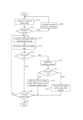
- FIG. 3 is a flow chart showing an example of a ship control method according to an embodiment of the present invention
- FIGs. 4(A) and 4(B) are graphs simulating changes in heading during turning according to an embodiment of the present invention
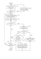
- FIG. 5 is a flow chart showing another example of a ship control method according to an embodiment of the present invention
- FIG. 6 is a flow chart showing yet another example of a ship control method according to an embodiment of the present invention.
- FIG.1 is a functional block diagram showing the configuration of a control unit ( hereinafter also referred to as processing circuitry) according to the embodiment of the present invention.
- FIG. 2 is a functional block diagram showing the configuration of the ship control system according to the embodiment of the present invention.
- the ship control system 10 includes a control unit 20, an operation unit 30, an observation value acquiring unit 40, and a display 50.
- the ship control system 10 is installed on a ship performing an autopilot control (i.e., an automatic navigation control).
- the control unit 20 corresponds to a ship control device of the present invention.
- the control unit 20 of the ship control system 10 is connected to a rudder 90.
- the rudder 90 is mounted on the ship.
- the control unit 20 and the rudder 90 are connected, for example, through an analog voltage signal line or a data communication line.
- propulsion generating devices such as screw propellers are further installed on the ship.
- the control unit 20 further controls generation of propulsion to the propulsion generating devices, but a detailed explanation is omitted here.
- the control unit 20, the operation unit 30, the observation value acquiring unit 40, and the display 50 are connected to each other by, for example, a data communication network 100 for vessels.
- the control unit 20 generates a turning signal based on a command rudder angle and outputs the turning signal to the rudder 90.
- the steering controls the rudder 90 according to the received turning signal.
- the specific generation method of the command rudder angle may be described later.
- the operation unit 30 is realized by, for example, a touch panel, physical buttons or switches.
- the operating unit 30 accepts an operation of settings related to the autopilot control including a target position and the like.
- the operating unit 30 outputs information (e.g., target position and the like) set by the operation to the control unit 20.
- the observation value acquiring unit 40 includes a bearing sensor and measures the heading ⁇ h.
- the observation value acquiring unit 40 measures the heading ⁇ h at a predetermined sampling period.
- the observation value acquiring unit 40 further outputs the heading ⁇ h to the control unit 20.
- the observation value acquiring unit 40 includes an angular velocity sensor and the like to measure a rate of turn ⁇ .
- the observation value acquiring unit 40 may calculate the rate of turn ⁇ from a time derivative of the heading ⁇ h over a plurality of times.
- the observation value acquiring unit 40 outputs the rate of turn ⁇ to the control unit 20.
- the display 50 is realized by, for example, a liquid crystal panel.
- the display 50 displays the information.
- the display 50 may be omitted, it is preferable to have one, and by having the display 50, the user may easily grasp the autopilot control status.
- the control unit 20 is composed of, for example, an arithmetic processing unit such as a Central Processing Unit (CPU) and a storage unit such as a semiconductor memory.
- the storage unit stores a program to be executed by the control unit 20.
- the storage unit is utilized during computing the CPU.
- control unit 20 includes an overshoot amount measuring unit 21, a heading standard deviation calculating unit 22, a rudder angle offset calculation unit 23, a command rudder angle generating unit 24, an overshoot determining unit 28, and a course keeping determining unit 29.
- a set heading ⁇ set, the heading ⁇ h, and the rate of turn ⁇ are provided as an input to the control unit 20.
- the set heading ⁇ set, the heading ⁇ h, and the rate of turn ⁇ are provided as an input to the overshoot determining unit 28. Based on the set heading direction ⁇ set, the heading ⁇ h, and the rate of turn ⁇ , the overshoot determining unit 28 determines an occurrence of an overshoot during turning of the ship.
- the overshoot determining unit 28 determines whether the overshoot is in progress or is ended.
- the overshoot determining unit 28 determines whether the overshoot is in progress or is completed based on the following formula.
- Thovsd are signs (“+” or “-”) indicating the turning direction with a positive clockwise direction based on the heading. Further, ⁇ is the rate of turn with the positive clockwise direction based on the heading.
- Thovs is a threshold for determining the overshoot and is set at, for example, 3 degrees. The threshold Thovs for determining the overshoot is appropriately determined according to the past behavior of the ship and user settings.
- the overshoot determining unit 28 outputs whether the overshoot is in progress or the overshoot is finished (i.e., not in progress) to the overshoot amount measuring unit 21, the rudder angle offset amount calculating unit 23, and the command rudder angle generating unit 24.
- the set heading ⁇ set and the heading ⁇ h are provided as an input to the overshoot amount measuring unit 21. If the overshoot is in progress, the overshoot amount measuring unit 21 measures the overshoot amount, ⁇ ovs, based on the set heading, ⁇ set, and the heading, ⁇ h.
- the overshoot amount measuring unit 21 continuously records the difference between the heading, ⁇ h, and the set heading direction, ⁇ set (i.e., the excessive turning amount of the heading) at a predetermined time interval.
- the maximum value of the excessive turning amount of the heading measured in the plurality of times in one turn is defined as the overshoot amount, ⁇ ovs, in this turn.
- the overshoot amount measuring unit 21 outputs the overshoot amount, ⁇ ovs, to the rudder angle offset amount calculating unit 23.
- the rate of turn (i.e., turning angle speed), ⁇ , is provided as an input to the course keeping determining unit 29. Based on the rate of turn, ⁇ , the course keeping determining unit 29 determines whether the course keeping state or the altering state (i.e., turning state) is present. Specifically, if an absolute value of the rate of turn, ⁇ , is less than a course keeping state threshold, the course keeping state is determined. If the absolute value of the rate of turn, ⁇ , is not less than the course keeping state threshold, the altering state is determined.
- the course keeping determining unit 29 outputs at least one of the course keeping state and the altering state to the heading standard deviation calculating unit 22.
- the heading ⁇ h is provided as an input to the heading standard deviation calculating unit 22.
- the heading standard deviation calculating unit 22 calculates a standard deviation ⁇ psi of the heading ⁇ h at a plurality of times.
- the heading standard deviation calculating unit 22 preferably calculates the standard deviation ⁇ psi using the heading ⁇ h at the plurality of times in a needle holding state.
- the standard deviation, ⁇ psi, of the heading ⁇ h calculated in this way represents the shaking of the heading ⁇ h due to disturbances such as waves.
- the heading standard deviation calculating unit 22 outputs the standard deviation ⁇ psi of heading ⁇ h to the rudder angle offset amount calculating unit 23.
- the rudder angle offset amount calculating unit 23 calculates a rudder angle offset amount, ⁇ off, based on the overshoot amount, ⁇ ovs, and the standard deviation ⁇ psi of heading ⁇ h.
- the rudder angle offset amount calculating unit 23 calculates the rudder angle offset amount, ⁇ off, in the turning state.
- the rudder angle offset amount calculating unit 23 calculates a correction value (i.e., rudder angle offset amount correction value, ⁇ off) of the rudder angle offset amount, ⁇ off, based on a difference value between an absolute value ABS ⁇ ovs of the overshoot amount, ⁇ ovs, and the standard deviation, ⁇ psi, of the heading, ⁇ h.
- the equation 1 is used to calculate the correction value.
- ⁇ off k (ABS ⁇ ovs- ⁇ psi)... (1)
- k is a coefficient for calculating the offset and is set at k ⁇ 1.0.
- k 0.3, but may be set appropriately within k ⁇ 1.0.
- the rudder angle offset amount calculating unit 23 may calculate the rudder angle offset correction value, ⁇ off, with high accuracy.
- the rudder angle offset amount calculating unit 23 calculates the rudder angle offset amount, ⁇ off(n), at a turn of time (n) based on an absolute value, ABS ⁇ off (n-1), of the rudder angle offset amount, ⁇ off(n-1), at a turn of the previous time (n-1) and the rudder angle offset amount correction value, ⁇ off(n).
- the rudder angle offset amount at the turn of the time (n) i.e., ⁇ off (n) is calculated using equation 2.
- ⁇ off(n) (ABS ⁇ off(n-1)+ ⁇ off)...(2)
- the rudder angle offset amount calculating unit 23 calculates the rudder angle offset amount, ⁇ off, at each turn. When the overshoot is completed, the rudder angle offset amount calculating unit 23 outputs the calculated rudder angle offset amount, ⁇ off, to the command rudder angle generating unit 24. That is during the turning of the ship, the rudder angle offset ⁇ off (n) calculated at that time is not yet output to the command rudder angle generating unit 24.
- the heading ⁇ h, the set heading ⁇ set, and the rudder angle offset ⁇ off(n-1) obtained in previous turning are provided as an input to the command rudder angle generating unit 24.
- the command rudder angle generating unit 24 calculates the command rudder angle using a Proportional-Integral-Derivative (PID) control algorithm based on the heading ⁇ h, a target heading ⁇ obj set from the set heading ⁇ set, and the rudder angle measurement values.
- PID Proportional-Integral-Derivative
- the command rudder angle generating unit 24 corrects the command rudder angle by adding or subtracting the previous rudder angle offset amount ⁇ off (n-1) to the command rudder angle calculated by the PID control algorithm. More specifically, the command rudder angle generating unit 24 performs subtraction if a current turn is a right turn and adds if the current turn is a left turn. The command rudder angle generating unit 24 generates a turning signal based on the corrected command rudder angle and outputs the turning signal to the rudder 90.
- control unit 20 may properly correct the command rudder angle based on the overshoot amount. This suppresses the overshoot of the ship mounted with the ship control system 10.
- FIG. 3 is a flow chart showing an example of a ship control method according to an embodiment of the present invention. It should be noted that the specific details of each process shown in the flow chart of FIG. 3 are described above, and only the parts requiring additional explanation may be explained below.
- the control unit 20 calculates the command rudder angle (S11). If the needle is being held (S12: YES), the control unit 20 calculates the standard deviation ⁇ psi of the heading ⁇ h (S200).
- control unit 20 calculates the command rudder angle using PID control or the like based on the set heading ⁇ set and heading ⁇ h at each timing during the turn (S13).
- the control unit 20 further measures the excessive turning amount of heading ⁇ h (S14). If the overshoot is not completed (S15: NO), the control unit 20 stores the maximum value of a plurality of excessive turning amount in one turn as the overshoot amount ⁇ ovs (S16).
- control unit 20 corrects the command rudder angle by adding the previous rudder offset amount ⁇ off(n-1) to the command rudder angle calculated by the PID control (S18).
- the control unit 20 calculates the current rudder offset amount ⁇ off(n) (S19). With this, the control unit 20 updates the rudder offset amount ⁇ off for each turn control.
- the control unit 20 repeats the above process.
- the control unit 20 holds the updated rudder angle offset amount, ⁇ off, for the next turning control.
- FIGs. 4(A) and 4(B) are graphs that simulate the change in heading during turning according to an embodiment of the present invention.
- FIG. 4(A) shows the case without a disturbance
- FIG. 4(B) shows the case with the disturbance.
- a solid line indicates a change in the heading when a turning control is performed
- a dashed line indicates a change in a reference heading ⁇ ref.
- the reference heading ⁇ ref is the heading during the turning without overshooting (i.e., hypothetical without considering the actual behavior of the ship).
- black triangle marks shown in FIGs. 4(A) and 4(B) indicate where the turning control is performed and where the overshooting occurs.
- the rudder angle offset amount, ⁇ off is not set during a first turning control.
- the overshoot amount is smaller during a second and subsequent turning control compared to the first turning control.
- the ship control system 10 may effectively suppress the overshoot.
- the ship control system 10 may effectively suppress the overshoot by using the standard deviation, ⁇ psi, of the heading, ⁇ h, to calculate the rudder angle offset amount, ⁇ off, as described above.
- FIG. 5 is a flow chart showing another example of a ship control method according to an embodiment of the present invention. It should be noted that the specific details of each process shown in the flow chart of FIG. 5 have been described above, and only the parts requiring additional explanation may be described below. The processing shown in the flowchart of FIG. 5has the same parts as the processing shown in the flowchart of FIG. 3, and only the different parts may be described below.
- the control unit 20 After storing the overshoot amount ⁇ ovs, the control unit 20 compares the overshoot amount ⁇ ovs (i.e., the maximum value of the excessive turning amount) with a correction threshold if the overshoot is not finished (S17: NO).
- the control unit 20 adds the previous rudder angle offset amount ⁇ off (n-1) to the command rudder angle calculated by the PID control to correct the command rudder angle (S18).
- the control unit 20 may not correct the command rudder angle. That is, the control unit 20 may not correct the command rudder angle calculated by PID control by the previous rudder angle offset amount ⁇ off (n-1).
- Such control prevents the ship control system 10 from correcting the command rudder angle even though the overshoot amount is small. Therefore, the ship control system 10 may suppress unwanted increases in the overshoot amount. Thus, the ship control system 10 may suppress an increase in the overshoot amount again after the overshoot amount is suppressed by the treatment described above.
- the rudder angle offset amount, ⁇ off may be set to be constant regardless of a size of a turning angle.
- the rudder angle offset amount, ⁇ off may be set according to the size of the turning angle.
- the rudder angle offset amount calculating unit 23 calculates a current rudder angle offset amount, ⁇ off (n), using a previous correction factor, kag(n-1), corresponding to a previous rudder angle offset amount, ⁇ off (n-1), and the size of the turning angle (i.e., turning angle in one turning), and the following equation 3.
- ⁇ off (n) (1/kag(n-1)) ⁇ (ABS(kag(n-1) ⁇ off (n-1)+ ⁇ off))...(3)
- the rudder angle offset amount, ⁇ off (n) becomes a normalized value because an influence of the magnitude of the turning angle is suppressed.
- the command rudder angle generating unit 24 calculates the current command rudder angle using the rudder angle offset amount, ⁇ off (n), normalized according to the magnitude of the turning angle in this way. Specifically, the command rudder angle generating unit 24 multiplies (i.e., denormalizes) the normalized rudder angle offset amount, ⁇ off (n), by a correction factor, kag(n), according to a current turning angle. The command rudder angle generating unit 24 calculates the current command rudder angle by adding or subtracting the multiplication value (i.e., denormalized rudder angle offset amount) to or from the command rudder angle calculated by the PID control algorithm. The current turning angle may be obtained based on a new setting direction and a current setting direction.
- the output command rudder angle is corrected by the rudder angle offset amount corresponding to the size of the turning angle, and the command rudder angle is properly corrected according to the size of the turning angle.
- FIG. 6 is a flow chart showing yet another example of the ship control method according to an embodiment of the present invention. It should be noted that the specific details of each process shown in the flow chart of FIG. 6 have been described above, and only the parts requiring additional explanation may be described below. The process shown in the flow chart of FIG. 6 has the same parts as the process shown in the flow chart of FIG. 3, and only the different parts may be described below.
- the control unit 20 acquires the current turning angle (S191).
- the control unit 20 sets a correction factor kag(n) corresponding to the current turning angle, and calculates the current rudder angle offset amount ⁇ off (n) using the correction factor kag (S192).
- All processes described herein may be embodied in, and fully automated via, software code modules executed by a computing system that includes one or more computers or processors.
- the software code modules may be stored in any type of non-transitory computer-readable medium or other computer storage device. Some or all methods may be embodied in specialized computer hardware.
- the various exemplary logical blocks and modules described in connection with the embodiments disclosed herein can be implemented or executed by a machine such as a processor.
- the processor may be a microprocessor, but alternatively, the processor may be a controller, a microcontroller, or a state machine, or a combination thereof.
- the processor can include an electrical circuit configured to process computer executable instructions.
- the processor includes an application specific integrated circuit (ASIC), a field programmable gate array (FPGA), or other programmable device that performs logical operations without processing computer executable instructions.
- ASIC application specific integrated circuit
- FPGA field programmable gate array
- the processor can also be implemented as a combination of computing devices, e.g., a combination of a digital signal processor (DSP) and a microprocessor, a plurality of microprocessors, one or more microprocessors in conjunction with a DSP core, or any other such configuration.
- DSP digital signal processor
- a computing environment may include any type of computer system, including, but not limited to, a computer system that is based on a microprocessor, mainframe computer, a digital signal processor, a portable computing device, a device controller, or a computing engine within the device.
- conditional languages such as “can,” “could,” “will,” “might,” or “may” are understood within the context as used in general to convey that certain embodiments include, while other embodiments do not include, certain features, elements and/or steps.?Thus, such conditional languages are not generally intended to imply that features, elements and/or steps are in any way required for one or more embodiments or that one or more embodiments necessarily include logic for deciding, with or without user input or prompting, whether these features, elements and/or steps are included or are to be performed in any particular embodiment.
- Disjunctive languages such as the phrase “at least one of X, Y, or Z,” unless specifically stated otherwise, is understood with the context as used in general to present that an item, term, etc., may be either X, Y, or Z, or any combination thereof (e.g., X, Y, and/or Z).?Thus, such a disjunctive language is not generally intended to, and should not, imply that certain embodiments require at least one of X, at least one of Y, or at least one of Z to each be present.
- a device configured to are intended to include one or more recited devices. Such one or more recited devices can also be collectively configured to carry out the stated recitations.
- a processor configured to carry out recitations A, B and C can include a first processor configured to carry out recitation A working in conjunction with a second processor configured to carry out recitations B and C. The same holds true for the use of definite articles used to introduce embodiment recitations.
- the term “horizontal” as used herein is defined as a plane parallel to the plane or surface of the floor of the area in which the system being described is used or the method being described is performed, regardless of its orientation.
- the term “floor” can be interchanged with the term “ground” or “water surface”.
- the term “vertical” refers to a direction perpendicular to the horizontal as just defined. Terms such as “above,” “below,” “bottom,” “top,” “side,” “higher,” “lower,” “upper,” “over,” and “under” are defined with respect to the horizontal plane.
- connection As used herein, the terms “attached,” “connected,” “coupled,” and other such relational terms should be construed, unless otherwise noted, to include removable, moveable, fixed, adjustable, and/or releasable connections or attachments.
- the connections/attachments can include direct connections and/or connections having intermediate structure between the two components discussed.
- Numbers preceded by a term such as “approximately,” “about,” and “substantially” as used herein include the recited numbers, and also represent an amount close to the stated amount that still performs a desired function or achieves a desired result.
- the terms “approximately,” “about,” and “substantially” may refer to an amount that is within less than 10% of the stated amount.
- Features of embodiments disclosed herein preceded by a term such as “approximately,” “about,” and “substantially” as used herein represent the feature with some variability that still performs a desired function or achieves a desired result for that feature.
Landscapes
- Chemical & Material Sciences (AREA)
- Engineering & Computer Science (AREA)
- Combustion & Propulsion (AREA)
- Mechanical Engineering (AREA)
- Ocean & Marine Engineering (AREA)
- Feedback Control In General (AREA)
- Control Of Position, Course, Altitude, Or Attitude Of Moving Bodies (AREA)
Abstract
The object of the present invention is to effectively suppress an overshoot of a heading during turning. A ship control device is provided with an overshoot amount measuring unit (21) and a rudder angle offset amount calculating unit (23). The overshoot amount measuring unit (21) measures an overshoot amount of a heading during turning based on the overshoot amount of the heading to a set heading of a ship during autopilot control. The rudder angle offset amount calculating unit (23) calculates a rudder angle offset amount based on the overshoot amount.
Description
The present invention relates to ship control during turning.
Patent Document 1 describes an automatic ship steering system. The automatic ship steering system described in Patent Document 1 uses differential preceding type Proportional-Integral-Derivative (PID) control to suppress the development of a rate of turn.
Patent Document 1: Japanese Unexamined Patent Application Publication No. 2001-18893.
However, it is difficult to effectively suppress an overshoot of a heading during turning with a conventional technology including the device of Patent Document 1.
Therefore, the object of the present invention is to effectively suppress the overshoot of the heading during turning.
A ship control device is provided with an overshoot amount measuring unit and a rudder angle offset amount calculating unit. The overshoot amount measuring unit measures an overshoot amount of a heading during turning, based on the overshoot amount of the heading with respect to a set heading of a ship. The rudder angle offset amount calculating unit calculates a rudder angle offset amount that suppresses an overshoot during turning, based on the overshoot amount.
In this configuration, the rudder angle offset amount that corrects a command rudder angle is calculated based on the overshoot amount. Thus, the command rudder angle is properly corrected for the overshoot. Therefore, the overshoot of the heading during turning may be effectively suppressed.
In the ship control device of the present invention, the overshoot amount measuring unit measures the overshoot amount every time the overshoot occurs in a plurality of turnings. The rudder angle offset amount calculating unit further calculates and updates the rudder angle offset amount every time the overshoot amount is measured.
In this configuration, the rudder angle offset amount is properly updated according to the overshoot amount.
In the ship control device of the present invention, the overshoot amount measuring unit sets a maximum value of the excessive turning amount measured a plurality of times in one turn as the overshoot amount.
In this configuration, the overshoot amount is properly set from the excessive turning amount in the heading.
In addition, the ship control device of this invention is equipped with a command rudder angle generation unit. The command rudder angle generation unit sets the command rudder angle based on the set heading and the heading, and outputs the command rudder angle corrected by the rudder angle offset amount. The command rudder angle generation unit corrects the command rudder angle by the rudder angle offset amount when the maximum value of the overshoot amount is equal to or greater than a correction threshold.
In this configuration, undesirable instability in the behavior of the ship is restrained when the overshoot is within a defined range.
The ship control device of this invention further includes a heading standard deviation calculating unit. The heading standard deviation calculating unit calculates a standard deviation of the heading. Further, the rudder angle offset amount calculating unit calculates the rudder angle offset amount based on the overshoot amount and the standard deviation of the heading.
In this configuration, an influence of a disturbance on the rudder angle offset amount is suppressed.
In the ship control device of the present invention, the heading standard deviation calculating unit calculates the standard deviation of the heading when the ship is held.
In this configuration, the standard deviation of the heading is accurately calculated.
In the ship control device of this invention, the rudder angle offset amount calculating unit is provided with a rudder angle offset correcting unit that calculates a correction value of the rudder angle offset amount based on a difference between the overshoot amount and the standard deviation of the heading. The rudder angle offset correcting unit further corrects the rudder angle offset amount by adding the correction value and the rudder angle offset amount calculated during a past turning.
In this configuration, the rudder angle offset amount is calculated accurately.
In the ship control device of this invention, the rudder angle offset amount calculating unit calculates a normalized rudder angle offset amount based on a turning angle. Further, a command rudder angle generation unit corrects the command rudder angle based on the normalized rudder angle offset amount.
In this configuration, the rudder angle offset amount according to a size of the turning angle is calculated, and the command rudder angle properly corrected according to the size of the turning angle is calculated.
Further, in the ship control device of this invention, the command rudder angle generating unit generates a denormalized rudder angle offset amount based on multiplying the normalized rudder angle offset amount by the current turning angle. Further, the command rudder angle generating unit corrects the command rudder angle based on the denormalized rudder angle offset amount.
In this configuration, the command rudder angle is corrected precisely according to a magnitude of the current turning angle.
In addition, the ship control device of this invention is provided with an overshoot determining unit. The overshoot determining unit determines an occurrence of the overshoot based on the heading, the set heading, and a rate of turn of the ship. The overshoot amount measuring unit further measures the overshoot amount when the overshoot occurs.
In this configuration, the overshoot amount is accurately measured.
In addition, the ship control system of the present invention is equipped with the ship control device described above and an observation value acquiring unit for acquiring an observation value associated with a behavior of the ship including the heading.
In this configuration, as a ship control system, the overshoot amount of the heading during turning may be effectively suppressed.
The illustrated embodiments of the subject matter will be best understood by reference to the drawings, wherein like parts are designated by like numerals throughout. The following description is intended only by way of example, and simply illustrates certain selected embodiments of devices, systems, and processes that are consistent with the subject matter as claimed herein.
FIG. 1 is a functional block diagram showing the configuration of a control unit according to an embodiment of the present invention;
FIG. 2 is a functional block diagram showing the configuration of a ship control system according to an embodiment of the present invention;
FIG. 3 is a flow chart showing an example of a ship control method according to an embodiment of the present invention;
FIGs. 4(A) and 4(B) are graphs simulating changes in heading during turning according to an embodiment of the present invention;
FIG. 5 is a flow chart showing another example of a ship control method according to an embodiment of the present invention; and
FIG. 6 is a flow chart showing yet another example of a ship control method according to an embodiment of the present invention.
Example apparatus are described herein. Other example embodiments or features may further be utilized, and other changes may be made, without departing from the spirit or scope of the subject matter presented herein. In the following detailed description, reference is made to the accompanying drawings, which form a part thereof.
The example embodiments described herein are not meant to be limiting. It will be readily understood that the aspects of the present disclosure, as generally described herein, and illustrated in the drawings, can be arranged, substituted, combined, separated, and designed in a wide variety of different configurations, all of which are explicitly contemplated herein.
A ship control device, a ship control system, a ship control method and a ship control program according to the embodiment of the invention will be explained with reference to the figures. FIG.1 is a functional block diagram showing the configuration of a control unit ( hereinafter also referred to as processing circuitry) according to the embodiment of the present invention. FIG. 2 is a functional block diagram showing the configuration of the ship control system according to the embodiment of the present invention.
(Configuration of a ship control system 10) First, a ship control system 10 will be explained using FIG. 2. As shown in FIG. 2, the ship control system 10 includes a control unit 20, an operation unit 30, an observation value acquiring unit 40, and a display 50. The ship control system 10 is installed on a ship performing an autopilot control (i.e., an automatic navigation control). The control unit 20 corresponds to a ship control device of the present invention.
The control unit 20 of the ship control system 10 is connected to a rudder 90. The rudder 90 is mounted on the ship. The control unit 20 and the rudder 90 are connected, for example, through an analog voltage signal line or a data communication line.
Although not shown, propulsion generating devices such as screw propellers are further installed on the ship. The control unit 20 further controls generation of propulsion to the propulsion generating devices, but a detailed explanation is omitted here.
The control unit 20, the operation unit 30, the observation value acquiring unit 40, and the display 50 are connected to each other by, for example, a data communication network 100 for vessels.
The control unit 20 generates a turning signal based on a command rudder angle and outputs the turning signal to the rudder 90. The steering controls the rudder 90 according to the received turning signal. The specific generation method of the command rudder angle may be described later.
The operation unit 30 is realized by, for example, a touch panel, physical buttons or switches. The operating unit 30 accepts an operation of settings related to the autopilot control including a target position and the like. The operating unit 30 outputs information (e.g., target position and the like) set by the operation to the control unit 20.
The observation value acquiring unit 40 includes a bearing sensor and measures the heading ψh. The observation value acquiring unit 40 measures the heading ψh at a predetermined sampling period. The observation value acquiring unit 40 further outputs the heading ψh to the control unit 20.
In addition, the observation value acquiring unit 40 includes an angular velocity sensor and the like to measure a rate of turn ω. The observation value acquiring unit 40 may calculate the rate of turn ω from a time derivative of the heading ψh over a plurality of times.
The observation value acquiring unit 40 outputs the rate of turn ω to the control unit 20.
The display 50 is realized by, for example, a liquid crystal panel. When, for example, information related to the autopilot control is provided as an input from the control unit 20, the display 50 displays the information. Although the display 50 may be omitted, it is preferable to have one, and by having the display 50, the user may easily grasp the autopilot control status.
(Configuration of the control unit 20 and specific processing) The control unit 20 is composed of, for example, an arithmetic processing unit such as a Central Processing Unit (CPU) and a storage unit such as a semiconductor memory. The storage unit stores a program to be executed by the control unit 20. In addition, the storage unit is utilized during computing the CPU.
As shown in FIG. 1, functionally, the control unit 20 includes an overshoot amount measuring unit 21, a heading standard deviation calculating unit 22, a rudder angle offset calculation unit 23, a command rudder angle generating unit 24, an overshoot determining unit 28, and a course keeping determining unit 29.
Further, a set heading ψset, the heading ψh, and the rate of turn ω are provided as an input to the control unit 20.
The set heading ψset, the heading ψh, and the rate of turn ω are provided as an input to the overshoot determining unit 28. Based on the set heading direction ψset, the heading ψh, and the rate of turn ω, the overshoot determining unit 28 determines an occurrence of an overshoot during turning of the ship.
Based on a turning direction, the rate of turn ω, and an azimuth difference between the heading ψh and the set heading ψset, the overshoot determining unit 28 determines whether the overshoot is in progress or is ended.
More specifically, the overshoot determining unit 28 determines whether the overshoot is in progress or is completed based on the following formula.
d・ω < 0.0, and d・(ψh-ψset) < Thovsd are signs (“+” or “-”) indicating the turning direction with a positive clockwise direction based on the heading. Further, ω is the rate of turn with the positive clockwise direction based on the heading. Thovs is a threshold for determining the overshoot and is set at, for example, 3 degrees. The threshold Thovs for determining the overshoot is appropriately determined according to the past behavior of the ship and user settings.
The overshoot determining unit 28 outputs whether the overshoot is in progress or the overshoot is finished (i.e., not in progress) to the overshoot amount measuring unit 21, the rudder angle offset amount calculating unit 23, and the command rudder angle generating unit 24.
The set heading ψset and the heading ψh are provided as an input to the overshoot amount measuring unit 21. If the overshoot is in progress, the overshoot amount measuring unit 21 measures the overshoot amount, ψovs, based on the set heading, ψset, and the heading, ψh.
More specifically, the overshoot amount measuring unit 21 continuously records the difference between the heading, ψh, and the set heading direction, ψset (i.e., the excessive turning amount of the heading) at a predetermined time interval. In the overshoot amount measuring unit 21, the maximum value of the excessive turning amount of the heading measured in the plurality of times in one turn is defined as the overshoot amount, ψovs, in this turn.
The overshoot amount measuring unit 21 outputs the overshoot amount, ψovs, to the rudder angle offset amount calculating unit 23.
The rate of turn (i.e., turning angle speed), ω, is provided as an input to the course keeping determining unit 29. Based on the rate of turn, ω, the course keeping determining unit 29 determines whether the course keeping state or the altering state (i.e., turning state) is present. Specifically, if an absolute value of the rate of turn, ω, is less than a course keeping state threshold, the course keeping state is determined. If the absolute value of the rate of turn, ω, is not less than the course keeping state threshold, the altering state is determined.
The course keeping determining unit 29 outputs at least one of the course keeping state and the altering state to the heading standard deviation calculating unit 22.
The heading ψh is provided as an input to the heading standard deviation calculating unit 22. The heading standard deviation calculating unit 22 calculates a standard deviation σpsi of the heading ψh at a plurality of times. In this case, the heading standard deviation calculating unit 22 preferably calculates the standard deviation σpsi using the heading ψh at the plurality of times in a needle holding state. By using the heading ψh at the plurality of times in the needle holding state, it is not affected by changes in the heading ψh during turning. Therefore, by using the heading ψh at the plurality of times in the needle holding state, the standard deviation σpsi of the heading ψh is calculated with high accuracy.
The standard deviation, σpsi, of the heading ψh calculated in this way represents the shaking of the heading ψh due to disturbances such as waves.
The heading standard deviation calculating unit 22 outputs the standard deviation σpsi of heading ψh to the rudder angle offset amount calculating unit 23.
The rudder angle offset amount calculating unit 23 calculates a rudder angle offset amount, δoff, based on the overshoot amount, ψovs, and the standard deviation σpsi of heading ψh. The rudder angle offset amount calculating unit 23 calculates the rudder angle offset amount, δoff, in the turning state.
Specifically, the rudder angle offset amount calculating unit 23 calculates a correction value (i.e., rudder angle offset amount correction value, Δδoff) of the rudder angle offset amount, δoff, based on a difference value between an absolute value ABS ψovs of the overshoot amount, ψovs, and the standard deviation, σpsi, of the heading, ψh. The equation 1 is used to calculate the correction value.
Δδoff =k (ABS ψovs-σpsi)… (1)
Δδoff =k (ABS ψovs-σpsi)… (1)
It is to be noted that k is a coefficient for calculating the offset and is set at k<1.0. For example, k=0.3, but may be set appropriately within k<1.0.
Thus, by using the standard deviation, σpsi, of the heading, ψh, an influence of a disturbance on the rudder angle offset amount, δoff, and the rudder angle offset correction value, Δδoff, may be suppressed. Therefore, the rudder angle offset amount calculating unit 23 may calculate the rudder angle offset correction value, Δδoff, with high accuracy.
The rudder angle offset amount calculating unit 23 calculates the rudder angle offset amount, δoff(n), at a turn of time (n) based on an absolute value, ABS Δoff (n-1), of the rudder angle offset amount, δoff(n-1), at a turn of the previous time (n-1) and the rudder angle offset amount correction value, Δδoff(n). The rudder angle offset amount at the turn of the time (n) i.e., δoff (n) is calculated using equation 2.
Δoff(n)=(ABSδoff(n-1)+Δδoff)…(2)
Δoff(n)=(ABSδoff(n-1)+Δδoff)…(2)
The rudder angle offset amount calculating unit 23 calculates the rudder angle offset amount, δoff, at each turn. When the overshoot is completed, the rudder angle offset amount calculating unit 23 outputs the calculated rudder angle offset amount, δoff, to the command rudder angle generating unit 24. That is during the turning of the ship, the rudder angle offset δoff (n) calculated at that time is not yet output to the command rudder angle generating unit 24.
The heading ψh, the set heading ψset, and the rudder angle offset δoff(n-1) obtained in previous turning are provided as an input to the command rudder angle generating unit 24.
The command rudder angle generating unit 24 calculates the command rudder angle using a Proportional-Integral-Derivative (PID) control algorithm based on the heading ψh, a target heading ψobj set from the set heading ψset, and the rudder angle measurement values.
During the overshoot, the command rudder angle generating unit 24 corrects the command rudder angle by adding or subtracting the previous rudder angle offset amount δoff (n-1) to the command rudder angle calculated by the PID control algorithm. More specifically, the command rudder angle generating unit 24 performs subtraction if a current turn is a right turn and adds if the current turn is a left turn. The command rudder angle generating unit 24 generates a turning signal based on the corrected command rudder angle and outputs the turning signal to the rudder 90.
With such a configuration and control, the control unit 20 may properly correct the command rudder angle based on the overshoot amount. This suppresses the overshoot of the ship mounted with the ship control system 10.
(Ship control method) FIG. 3 is a flow chart showing an example of a ship control method according to an embodiment of the present invention. It should be noted that the specific details of each process shown in the flow chart of FIG. 3 are described above, and only the parts requiring additional explanation may be explained below.
The control unit 20 calculates the command rudder angle (S11). If the needle is being held (S12: YES), the control unit 20 calculates the standard deviation σpsi of the heading ψh (S200).
If the turn is in progress (S12: NO), the control unit 20 calculates the command rudder angle using PID control or the like based on the set heading ψset and heading ψh at each timing during the turn (S13).
The control unit 20 further measures the excessive turning amount of heading ψh (S14). If the overshoot is not completed (S15: NO), the control unit 20 stores the maximum value of a plurality of excessive turning amount in one turn as the overshoot amount ψovs (S16).
If the overshoot in the current turn control is not completed (S17: NO), the control unit 20 corrects the command rudder angle by adding the previous rudder offset amount δ off(n-1) to the command rudder angle calculated by the PID control (S18).
If the overshoot in the current turn control is completed (S15: YES), the control unit 20 calculates the current rudder offset amount δoff(n) (S19). With this, the control unit 20 updates the rudder offset amount δoff for each turn control.
During the execution of the current turning control (S20: NO), the control unit 20 repeats the above process. When the current turning control is completed (S20: YES), the control unit 20 holds the updated rudder angle offset amount, δoff, for the next turning control.
(Simulation result) FIGs. 4(A) and 4(B) are graphs that simulate the change in heading during turning according to an embodiment of the present invention. FIG. 4(A) shows the case without a disturbance, and FIG. 4(B) shows the case with the disturbance. In FIGs. 4(A) and 4(B), a solid line indicates a change in the heading when a turning control is performed, and a dashed line indicates a change in a reference heading ψref. The reference heading ψref is the heading during the turning without overshooting (i.e., hypothetical without considering the actual behavior of the ship).
In addition, black triangle marks shown in FIGs. 4(A) and 4(B) indicate where the turning control is performed and where the overshooting occurs. In FIG.4(A) and FIG. 4(B), the rudder angle offset amount, δoff, is not set during a first turning control.
As shown in FIG. 4(A) and FIG. 4(B), the overshoot amount is smaller during a second and subsequent turning control compared to the first turning control.
Thus, by using the configuration and control of the present invention, the ship control system 10 may effectively suppress the overshoot. In particular, as shown in FIG. 4(B), even in the presence of the disturbance, the ship control system 10 may effectively suppress the overshoot by using the standard deviation, σpsi, of the heading, ψh, to calculate the rudder angle offset amount, δoff, as described above.
(Another example of ship control method) FIG. 5 is a flow chart showing another example of a ship control method according to an embodiment of the present invention. It should be noted that the specific details of each process shown in the flow chart of FIG. 5 have been described above, and only the parts requiring additional explanation may be described below. The processing shown in the flowchart of FIG. 5has the same parts as the processing shown in the flowchart of FIG. 3, and only the different parts may be described below.
After storing the overshoot amount ψovs, the control unit 20 compares the overshoot amount ψovs (i.e., the maximum value of the excessive turning amount) with a correction threshold if the overshoot is not finished (S17: NO).
When the overshoot amount ψovs is equal to or greater than the correction threshold (S31: YES), the control unit 20 adds the previous rudder angle offset amount δoff (n-1) to the command rudder angle calculated by the PID control to correct the command rudder angle (S18).
When the overshoot amount ψovs is less than the correction threshold (S31: NO), the control unit 20 may not correct the command rudder angle. That is, the control unit 20 may not correct the command rudder angle calculated by PID control by the previous rudder angle offset amount δoff (n-1).
Such control prevents the ship control system 10 from correcting the command rudder angle even though the overshoot amount is small. Therefore, the ship control system 10 may suppress unwanted increases in the overshoot amount. Thus, the ship control system 10 may suppress an increase in the overshoot amount again after the overshoot amount is suppressed by the treatment described above.
(Another example of calculation method of the rudder angle offset amount and the command rudder angle) In the above configuration, the rudder angle offset amount, δoff, may be set to be constant regardless of a size of a turning angle. However, the rudder angle offset amount, δoff, may be set according to the size of the turning angle.
In this case, the rudder angle offset amount calculating unit 23 calculates a current rudder angle offset amount, δoff (n), using a previous correction factor, kag(n-1), corresponding to a previous rudder angle offset amount, δoff (n-1), and the size of the turning angle (i.e., turning angle in one turning), and the following equation 3.
δoff (n)=(1/kag(n-1))・(ABS(kag(n-1)・δoff (n-1)+ Δδoff))…(3)
δoff (n)=(1/kag(n-1))・(ABS(kag(n-1)・δoff (n-1)+ Δδoff))…(3)
Here, the correction factor kag according to a magnitude of the turning angle is set to 1.0 or less. For example, kag=0.7 if the magnitude of the turning angle is less than 30 degrees, kag=0.8 if the magnitude of the turning angle is 30 degrees to less than 60 degrees, kag=0.9 if the magnitude of the turning angle is 60 degrees to less than 90 degrees, and 1.0 if the magnitude of the turning angle is 90 degrees or more.
By performing such processing, the rudder angle offset amount, δoff (n), becomes a normalized value because an influence of the magnitude of the turning angle is suppressed.
Then, the command rudder angle generating unit 24 calculates the current command rudder angle using the rudder angle offset amount, δoff (n), normalized according to the magnitude of the turning angle in this way. Specifically, the command rudder angle generating unit 24 multiplies (i.e., denormalizes) the normalized rudder angle offset amount, δoff (n), by a correction factor, kag(n), according to a current turning angle. The command rudder angle generating unit 24 calculates the current command rudder angle by adding or subtracting the multiplication value (i.e., denormalized rudder angle offset amount) to or from the command rudder angle calculated by the PID control algorithm. The current turning angle may be obtained based on a new setting direction and a current setting direction.
By carrying out such processing, the output command rudder angle is corrected by the rudder angle offset amount corresponding to the size of the turning angle, and the command rudder angle is properly corrected according to the size of the turning angle.
FIG. 6 is a flow chart showing yet another example of the ship control method according to an embodiment of the present invention. It should be noted that the specific details of each process shown in the flow chart of FIG. 6 have been described above, and only the parts requiring additional explanation may be described below. The process shown in the flow chart of FIG. 6 has the same parts as the process shown in the flow chart of FIG. 3, and only the different parts may be described below.
If the overshoot in the current turning control is completed (S15: YES), the control unit 20 acquires the current turning angle (S191).
The control unit 20 sets a correction factor kag(n) corresponding to the current turning angle, and calculates the current rudder angle offset amount δoff (n) using the correction factor kag (S192).
(Description of sign)
10: Ship control system
20: Control unit
21: Overshoot amount measuring unit
22: Heading standard deviation calculating unit
23: Rudder angle offset calculating unit
24: Command rudder angle generating unit
25: Rudder angle offset correcting unit
28: Overshoot determining unit
29: Course keeping determining unit
30: Operation unit
40: Observation value acquiring unit
50: Display
90: Rudder
100: Data communication network
(Description of sign)
10: Ship control system
20: Control unit
21: Overshoot amount measuring unit
22: Heading standard deviation calculating unit
23: Rudder angle offset calculating unit
24: Command rudder angle generating unit
25: Rudder angle offset correcting unit
28: Overshoot determining unit
29: Course keeping determining unit
30: Operation unit
40: Observation value acquiring unit
50: Display
90: Rudder
100: Data communication network
It is to be understood that not necessarily all objectives or advantages may be achieved in accordance with any particular embodiment described herein.?Thus, for example, those skilled in the art will appreciate that certain embodiments may be configured to operate in a manner that achieves or optimizes one advantage or group of advantages as taught herein without necessarily achieving other objects or advantages as may be taught or suggested herein.
All processes described herein may be embodied in, and fully automated via, software code modules executed by a computing system that includes one or more computers or processors. The software code modules may be stored in any type of non-transitory computer-readable medium or other computer storage device. Some or all methods may be embodied in specialized computer hardware.
Many other variations other than those described herein will be apparent from this disclosure. For example, depending on the embodiment, certain actions, events, or functions of any of the algorithms described herein may be performed in different sequences, and may be added, merged, or excluded altogether (e.g., not all described actions or events are required to execute the algorithm). Moreover, in certain embodiments, operations or events are performed in parallel, for example, through multithreading, interrupt handling, or through multiple processors or processor cores, or on other parallel architectures, rather than sequentially. In addition, different tasks or processes can be performed by different machines and/or computing systems that can work together.
The various exemplary logical blocks and modules described in connection with the embodiments disclosed herein can be implemented or executed by a machine such as a processor.?The processor may be a microprocessor, but alternatively, the processor may be a controller, a microcontroller, or a state machine, or a combination thereof.?The processor can include an electrical circuit configured to process computer executable instructions.?In another embodiment, the processor includes an application specific integrated circuit (ASIC), a field programmable gate array (FPGA), or other programmable device that performs logical operations without processing computer executable instructions.?The processor can also be implemented as a combination of computing devices, e.g., a combination of a digital signal processor (DSP) and a microprocessor, a plurality of microprocessors, one or more microprocessors in conjunction with a DSP core, or any other such configuration. Although described herein primarily with respect to digital technology, the processor may also include primarily analog components.?For example, some or all of the signal processing algorithms described herein may be implemented by analog circuitry or mixed analog and digital circuitry. A computing environment may include any type of computer system, including, but not limited to, a computer system that is based on a microprocessor, mainframe computer, a digital signal processor, a portable computing device, a device controller, or a computing engine within the device.
Unless otherwise stated, conditional languages such as “can,” “could,” “will,” “might,” or “may” are understood within the context as used in general to convey that certain embodiments include, while other embodiments do not include, certain features, elements and/or steps.?Thus, such conditional languages are not generally intended to imply that features, elements and/or steps are in any way required for one or more embodiments or that one or more embodiments necessarily include logic for deciding, with or without user input or prompting, whether these features, elements and/or steps are included or are to be performed in any particular embodiment.
Disjunctive languages, such as the phrase “at least one of X, Y, or Z,” unless specifically stated otherwise, is understood with the context as used in general to present that an item, term, etc., may be either X, Y, or Z, or any combination thereof (e.g., X, Y, and/or Z).?Thus, such a disjunctive language is not generally intended to, and should not, imply that certain embodiments require at least one of X, at least one of Y, or at least one of Z to each be present.
Any process descriptions, elements, or blocks in the flow diagrams described herein and/or shown in the accompanying drawings should be understood as potentially representing modules, segments, or parts of code, including one or more executable instructions for implementing a particular logical function or elements in the process. Alternate implementations are included within the scope of the embodiments described herein in which elements or functions may be deleted, executed out of order from that shown, or discussed, including substantially concurrently or in reverse order, depending on the functionality involved as would be understood by those skilled in the art.
Unless otherwise explicitly stated, articles such as “a” or “an” should generally be interpreted to include one or more described items. Accordingly, phrases such as “a device configured to” are intended to include one or more recited devices. Such one or more recited devices can also be collectively configured to carry out the stated recitations. For example, “a processor configured to carry out recitations A, B and C” can include a first processor configured to carry out recitation A working in conjunction with a second processor configured to carry out recitations B and C. The same holds true for the use of definite articles used to introduce embodiment recitations. In addition, even if a specific number of an introduced embodiment recitation is explicitly recited, those skilled in the art will recognize that such recitation should typically be interpreted to mean at least the recited number (e.g., the bare recitation of “two recitations,” without other modifiers, typically means at least two recitations, or two or more recitations).
It will be understood by those within the art that, in general, terms used herein, are generally intended as “open” terms (e.g., the term “including” should be interpreted as “including but not limited to,” the term “having” should be interpreted as “having at least,” the term “includes” should be interpreted as “includes but is not limited to,” etc.).
For expository purposes, the term “horizontal” as used herein is defined as a plane parallel to the plane or surface of the floor of the area in which the system being described is used or the method being described is performed, regardless of its orientation. The term “floor” can be interchanged with the term “ground” or “water surface”. The term “vertical” refers to a direction perpendicular to the horizontal as just defined. Terms such as “above,” “below,” “bottom,” “top,” “side,” “higher,” “lower,” “upper,” “over,” and “under” are defined with respect to the horizontal plane.
As used herein, the terms “attached,” “connected,” “coupled,” and other such relational terms should be construed, unless otherwise noted, to include removable, moveable, fixed, adjustable, and/or releasable connections or attachments. The connections/attachments can include direct connections and/or connections having intermediate structure between the two components discussed.
Numbers preceded by a term such as “approximately,” “about,” and “substantially” as used herein include the recited numbers, and also represent an amount close to the stated amount that still performs a desired function or achieves a desired result. For example, the terms “approximately,” “about,” and “substantially” may refer to an amount that is within less than 10% of the stated amount. Features of embodiments disclosed herein preceded by a term such as “approximately,” “about,” and “substantially” as used herein represent the feature with some variability that still performs a desired function or achieves a desired result for that feature.
It should be emphasized that many variations and modifications may be made to the above-described embodiments, the elements of which are to be understood as being among other acceptable examples. All such modifications and variations are intended to be included herein within the scope of this disclosure and protected by the following claims.
Claims (13)
- A ship control device, comprising:
an overshoot amount measuring unit (21) configured to measure an overshoot amount of a heading of a ship during turning based on an excessive turning amount of the heading with respect to a set heading of the ship; and
a rudder angle offset amount calculating unit (23) configured to calculate a rudder angle offset amount that suppresses an overshoot during turning based on the overshoot amount.
- The ship control device of claim 1, wherein:
the overshoot amount measuring unit (21) is further configured to measure the overshoot amount every time the overshoot occurs in a plurality of turnings; and
the rudder angle offset amount calculating unit (23) is further configured to calculate and update the rudder angle offset amount every time the overshoot amount is measured.
- The ship control device of claim 1 or 2, wherein:
the overshoot amount measuring unit (21) is further configured to set a maximum value of the excessive turning amount measured a plurality of times in one turn as the overshoot amount.
- The ship control device of claim 3, further comprising:
a command rudder angle generating unit (24) configured to set a command rudder angle based on the set heading and the heading, and output the command rudder angle corrected by the rudder angle offset amount, wherein:
the command rudder angle generating unit (24) is further configured to correct the command rudder angle by the rudder angle offset amount when the maximum value of the overshoot amount is equal to or greater than a correction threshold.
- The ship control device of any one of claims 1 to 4, further comprising:
a heading standard deviation calculating unit (22) configured to calculate a standard deviation of the heading; and
the rudder angle offset amount calculating unit (23) is further configured to calculate the rudder angle offset amount based on the overshoot amount and the standard deviation of the heading.
- The ship control device of claim 5, wherein:
the heading standard deviation calculating unit (22) is further configured to calculate the standard deviation of the heading during course keeping of the ship.
- The ship control device of any one of claims 1 to 6, wherein:
the rudder angle offset amount calculation unit (23) is further comprising:
a rudder angle offset correcting unit (25) configured to calculate a correction value for the rudder angle offset amount based on a difference between the overshoot amount and the standard deviation of the heading, wherein:
the rudder angle offset correcting unit (25) is further configured to correct the rudder angle offset amount based on adding the correction value and the rudder angle offset amount calculated during a past turning.
- The ship control device of claim 4, wherein:
the rudder angle offset amount calculating unit (23) is further configured to calculate a normalized rudder angle offset amount based on a turning angle; and
the command rudder angle generating unit (24) is further configured to correct the command rudder angle based on the normalized rudder angle offset amount.
- The ship control device of claim 8, wherein:
the command rudder angle generating unit (24) is further configured to generate a denormalized rudder angle offset amount based on multiplying the normalized rudder angle offset amount by the turning angle; and
the command rudder angle generating unit (24) is further configured to correct the command rudder angle based on the denormalized rudder angle offset amount.
- The ship control device of any one of claims 1 to 9, further comprising:
an overshoot determining unit (28) configured to determine an occurrence of the overshoot based on the heading, the set heading, and a rate of turn, wherein
the overshoot amount measuring unit (21) is further configured to measure the overshoot amount in case the overshoot occurs.
- A ship control system (10) comprising the ship control device of claim 1, further comprising:
an observation value acquiring unit (40) configured to acquire an observation value associated with a behavior of the ship including the heading.
- A ship control method, comprising:
measuring an overshoot amount of a heading of a ship during turning based on an excessive turning amount of the heading with respect to a set heading of the ship; and
calculating a rudder angle offset amount that suppresses an overshoot during turning based on the overshoot amount.
- A ship control program that causes a computer to execute the processing, comprising:
measuring an overshoot amount of a heading of a ship during turning based on an excessive turning amount of the heading with respect to a set heading of the ship; and
calculating a rudder angle offset amount that suppresses an overshoot during turning based on the overshoot amount.
Priority Applications (1)
| Application Number | Priority Date | Filing Date | Title |
|---|---|---|---|
| US19/025,496 US20250153819A1 (en) | 2023-01-11 | 2025-01-16 | Ship control device, ship control method, ship control system, and computer readable medium |
Applications Claiming Priority (2)
| Application Number | Priority Date | Filing Date | Title |
|---|---|---|---|
| JP2023-002100 | 2023-01-11 | ||
| JP2023002100A JP2024098552A (en) | 2023-01-11 | 2023-01-11 | Hull control device, hull control method, hull control system, and hull control program |
Related Child Applications (1)
| Application Number | Title | Priority Date | Filing Date |
|---|---|---|---|
| US19/025,496 Continuation US20250153819A1 (en) | 2023-01-11 | 2025-01-16 | Ship control device, ship control method, ship control system, and computer readable medium |
Publications (1)
| Publication Number | Publication Date |
|---|---|
| WO2024150490A1 true WO2024150490A1 (en) | 2024-07-18 |
Family
ID=91896845
Family Applications (1)
| Application Number | Title | Priority Date | Filing Date |
|---|---|---|---|
| PCT/JP2023/037469 Ceased WO2024150490A1 (en) | 2023-01-11 | 2023-10-17 | Ship control device, ship control method, ship control system, and ship control program |
Country Status (3)
| Country | Link |
|---|---|
| US (1) | US20250153819A1 (en) |
| JP (1) | JP2024098552A (en) |
| WO (1) | WO2024150490A1 (en) |
Citations (1)
| Publication number | Priority date | Publication date | Assignee | Title |
|---|---|---|---|---|
| JP2008230484A (en) * | 2007-03-22 | 2008-10-02 | Yokogawa Denshikiki Co Ltd | Automatic steering device and automatic steering method |
Family Cites Families (6)
| Publication number | Priority date | Publication date | Assignee | Title |
|---|---|---|---|---|
| JP5528251B2 (en) * | 2010-08-04 | 2014-06-25 | 横河電子機器株式会社 | Automatic steering device |
| US8265812B2 (en) * | 2010-11-24 | 2012-09-11 | William M Pease | System and method for a marine vessel autopilot |
| US8589027B2 (en) * | 2010-12-02 | 2013-11-19 | Furuno Electric Company Limited | Steering assist system and method using autopilot device |
| JP2014193706A (en) * | 2013-02-27 | 2014-10-09 | Furuno Electric Co Ltd | Automatic steering device, automatic steering method and automatic steering program |
| AU2017218906B2 (en) * | 2016-02-10 | 2021-06-24 | Marine Canada Acquisition Inc. | System and method for positioning a marine vessel |
| US11530022B1 (en) * | 2018-07-10 | 2022-12-20 | Brunswick Corporation | Method for controlling heading of a marine vessel |
-
2023
- 2023-01-11 JP JP2023002100A patent/JP2024098552A/en active Pending
- 2023-10-17 WO PCT/JP2023/037469 patent/WO2024150490A1/en not_active Ceased
-
2025
- 2025-01-16 US US19/025,496 patent/US20250153819A1/en active Pending
Patent Citations (1)
| Publication number | Priority date | Publication date | Assignee | Title |
|---|---|---|---|---|
| JP2008230484A (en) * | 2007-03-22 | 2008-10-02 | Yokogawa Denshikiki Co Ltd | Automatic steering device and automatic steering method |
Also Published As
| Publication number | Publication date |
|---|---|
| JP2024098552A (en) | 2024-07-24 |
| US20250153819A1 (en) | 2025-05-15 |
Similar Documents
| Publication | Publication Date | Title |
|---|---|---|
| US20150199173A1 (en) | Multiply adder | |
| EP4220086A1 (en) | Combined navigation system initialization method and apparatus, medium, and electronic device | |
| US20130246496A1 (en) | Floating-point vector normalisation | |
| CN107228674B (en) | Improved method for combined filtering of star sensor and gyroscope | |
| CA2782275A1 (en) | Modified kalman filter for generation of attitude error corrections | |
| JPH0214714B2 (en) | ||
| CN112986977A (en) | Method for overcoming radar extended Kalman track filtering divergence | |
| US12536434B2 (en) | Computing method and apparatus for convolutional neural network model | |
| CN117409150A (en) | A method and system for improving the smoothness of three-dimensional display drone tracks | |
| US20230303232A1 (en) | Automatic steering device, automatic steering system, automatic steering method, and automatic steering program | |
| WO2024150490A1 (en) | Ship control device, ship control method, ship control system, and ship control program | |
| US11526580B2 (en) | Data correction method and apparatus, electronic device and computer-readable storage medium | |
| US12339662B2 (en) | Ship control device, ship control method, and ship control program | |
| CN119737980B (en) | A method and system for calibrating satellite inertial installation error based on iterative filtering | |
| CN115019150B (en) | Target detection fixed point model establishing method and device and readable storage medium | |
| US20230373600A1 (en) | Ship control device and ship control method | |
| CN106092135B (en) | Transition from stationary alignment mode to moving alignment mode | |
| CN116380056B (en) | Inertial positioning method, inertial positioning device, electronic equipment and storage medium | |
| CN113298879B (en) | Visual positioning method, device, storage medium and electronic device | |
| WO2020174935A1 (en) | Movement information calculation device and movement information calculation method | |
| JP2016133343A (en) | Offset calculation device and azimuth angle sensor using the same | |
| US11268814B2 (en) | Movement information calculating device, movement information calculating method and movement information calculating program | |
| CN117456007A (en) | Lidar and camera joint calibration method, device, equipment and storage medium | |
| CN104995584B (en) | Calculate magnetic heading | |
| US20240248489A1 (en) | Ship body control device, ship body control system, ship body control method and ship body control program |
Legal Events
| Date | Code | Title | Description |
|---|---|---|---|
| 121 | Ep: the epo has been informed by wipo that ep was designated in this application |
Ref document number: 23916109 Country of ref document: EP Kind code of ref document: A1 |
|
| NENP | Non-entry into the national phase |
Ref country code: DE |
|
| 122 | Ep: pct application non-entry in european phase |
Ref document number: 23916109 Country of ref document: EP Kind code of ref document: A1 |