WO2024150366A1 - 観測装置、制御方法、およびプログラム - Google Patents
観測装置、制御方法、およびプログラム Download PDFInfo
- Publication number
- WO2024150366A1 WO2024150366A1 PCT/JP2023/000585 JP2023000585W WO2024150366A1 WO 2024150366 A1 WO2024150366 A1 WO 2024150366A1 JP 2023000585 W JP2023000585 W JP 2023000585W WO 2024150366 A1 WO2024150366 A1 WO 2024150366A1
- Authority
- WO
- WIPO (PCT)
- Prior art keywords
- observation device
- wind
- propulsion mechanism
- wave
- observation
- Prior art date
- Legal status (The legal status is an assumption and is not a legal conclusion. Google has not performed a legal analysis and makes no representation as to the accuracy of the status listed.)
- Ceased
Links
Images





Classifications
-
- B—PERFORMING OPERATIONS; TRANSPORTING
- B63—SHIPS OR OTHER WATERBORNE VESSELS; RELATED EQUIPMENT
- B63B—SHIPS OR OTHER WATERBORNE VESSELS; EQUIPMENT FOR SHIPPING
- B63B22/00—Buoys
- B63B22/18—Buoys having means to control attitude or position, e.g. reaction surfaces or tether
-
- B—PERFORMING OPERATIONS; TRANSPORTING
- B63—SHIPS OR OTHER WATERBORNE VESSELS; RELATED EQUIPMENT
- B63B—SHIPS OR OTHER WATERBORNE VESSELS; EQUIPMENT FOR SHIPPING
- B63B35/00—Vessels or similar floating structures specially adapted for specific purposes and not otherwise provided for
- B63B35/34—Pontoons
-
- B—PERFORMING OPERATIONS; TRANSPORTING
- B63—SHIPS OR OTHER WATERBORNE VESSELS; RELATED EQUIPMENT
- B63H—MARINE PROPULSION OR STEERING
- B63H9/00—Marine propulsion provided directly by wind power
- B63H9/04—Marine propulsion provided directly by wind power using sails or like wind-catching surfaces
Definitions
- This disclosure relates to an observation device, a control method, and a program.
- Non-Patent Documents 1, 2, 3 The need for marine observations, such as monitoring global warming and climate change and investigating ecosystems, is increasing.
- observation equipment for marine observations, including those without a propulsion mechanism, those with a wave-power propulsion mechanism, and those with a wind-power propulsion mechanism.
- Satellite IoT technology which collects data from observation devices via satellites, is expected to be applied to ocean observation.
- To maximize the effectiveness of satellite IoT a large number of observation devices must be deployed over a wide area, making it essential to reduce the cost of the observation devices. Considering the cost of materials, and the maintenance costs of transportation, storage, etc., the smaller the observation device, the better.
- This disclosure has been made in consideration of the above, and aims to improve position control capabilities while miniaturizing the observation device.
- the observation device of one embodiment of the present disclosure is an observation device that floats on the ocean surface and is equipped with one or more sensors, a wind propulsion mechanism that converts wind force into a first propulsion force and can control the direction in which the first propulsion force acts, and a wave propulsion mechanism that converts wave force into a second propulsion force and can control the direction in which the second propulsion force acts, and controls the position of the observation device with a propulsion force that is a combination of the first propulsion force and the second propulsion force.
- the control method of one embodiment of the present disclosure is a control method for an observation device that controls its position with a combined propulsion force consisting of a first propulsion force obtained by converting wind power and a second propulsion force obtained by converting wave power, in which a computer predicts the position of the observation device after a predetermined time based on the first propulsion force determined by a combination of wind conditions and the control state of the observation device, the second propulsion force determined by a combination of wave conditions and the control state of the observation device, the wind conditions, and the wave conditions, and if the predicted position deviates from the target by more than an acceptable range, predicts the position of the observation device with the control state of the observation device changed, and determines an operation for the observation device so that the predicted position falls within an acceptable range from the target.
- This disclosure makes it possible to miniaturize the observation device while improving position control capabilities.
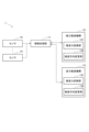
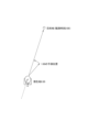
- FIG. 1 is a diagram showing an example of the configuration of an observation device according to this embodiment.
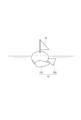
- FIG. 2 is a diagram showing an example of a wind power propulsion mechanism and a wave power propulsion mechanism provided in the observation device.
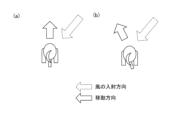
- FIG. 3 is a diagram showing an example of a movement direction according to the wind incidence direction and the control state of the wind propulsion mechanism.
- FIG. 4 is a diagram showing an example of a movement direction according to the wave incidence direction and the control state of the wave power propulsion mechanism.
- FIG. 5 is a diagram showing an example of a moving direction resulting from a combination of propulsive forces due to wind force and wave force.
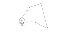
- FIG. 6 is a diagram showing an example of course adjustment to a destination.
- FIG. 7 is a diagram showing an example of course adjustment during observation at the same position.
- FIG. 8 is a flowchart showing an example of a process flow of the observation device.
- FIG. 9 is a flowchart showing an example of a process flow for determining an operation for the propulsion mechanism.
- FIG. 10 is a diagram showing an example of a control method for an observation device.
- FIG. 11 is a diagram showing an example of a control method for the observation device.
- FIG. 12 is a flowchart showing an example of the process flow of the observation device.
- FIG. 1 is a diagram showing an example of the configuration of an observation device of this embodiment.
- the observation device 1 shown in the figure includes an information processing unit 11, a wind power propulsion mechanism 12, a wave power propulsion mechanism 13, and one or more sensors 14.
- the information processing unit 11 controls the entire observation device 1. Specifically, the information processing unit 11 communicates with the satellite, acquires information from the sensor 14, and controls the wind power propulsion mechanism 12 and the wave power propulsion mechanism 13.
- the information processing unit 11 can be composed of a control microcomputer and memory. The processing of the information processing unit 11 may be executed by a program. This program is stored in a storage device provided in the observation device 1, and can be recorded on a non-transitory computer-readable recording medium such as a magnetic disk, optical disk, or semiconductor memory, or can be provided via a network.
- the information processing unit 11 may include a memory for storing observation data and a communication antenna.
- the information processing unit 11 may communicate with a satellite, or may communicate with a parent unit installed near the observation device 1.
- the observation device 1 is an observation device that floats on the sea surface.
- the wind propulsion mechanism 12 is attached to the top of the observation device 1 (above the sea surface), and the wave propulsion mechanism 13 is attached to the bottom of the observation device 1 (below the sea surface).
- the wind propulsion mechanism 12 includes a propulsion force converter 121 that converts wind into propulsion force, and a propulsion direction changer 122 that changes the direction in which the propulsion force acts, i.e., the propulsion direction, and provides propulsion force to the observation device 1 using wind force.
- the propulsion force converter 121 obtains propulsion force by using lift generated when receiving wind.
- the propulsion direction changer 122 may change the propulsion direction by changing the direction in which the sail receives the wind, as in sailing, for example.
- the wave power propulsion mechanism 13 is equipped with a propulsion force conversion unit 131 that converts waves into propulsion force, and a propulsion direction change unit 132 that changes the direction in which the propulsion force acts, i.e., the propulsion direction, and provides propulsion force to the observation device 1 using waves.
- the propulsion force conversion unit 131 converts the vertical movement of the observation device 1 caused by waves into propulsion force.
- the propulsion direction change unit 132 may change the orientation of the wave power propulsion mechanism 13 itself using power, or a ladder may be attached to the propulsion direction change unit 132 and the ladder may be moved to change the propulsion direction.
- Neither the wind propulsion mechanism 12 nor the wave propulsion mechanism 13 uses power to generate propulsive force.
- the sensor 14 is a sensor for measuring the physical quantities of the observation target and a sensor for obtaining environmental information around the observation device 1.
- the sensor 14 is a Conductivity Temperature Depth (CTD) sensor, a chlorophyll sensor, a camera, a Global Positioning System (GPS), an accelerometer, a current direction and speed meter, an anemometer, etc.
- CTD Conductivity Temperature Depth
- GPS Global Positioning System
- accelerometer a current direction and speed meter
- an anemometer etc.
- the observation device 1 is equipped with a battery for operating each part.
- the observation device 1 may also be equipped with a solar power generation panel for charging the battery.
- the observation device 1 or the remote device predicts the direction of movement of the observation device 1 due to wind and wave forces, and derives the operation of the wind propulsion mechanism 12 and the wave propulsion mechanism 13 so that the direction of movement is toward the destination.
- the remote device is, for example, a computer placed on land, and is capable of communicating with the observation device 1 via satellite. The operation derived by the remote device is transmitted to the observation device 1.
- the observation device 1 When the observation device 1 derives an operation, the observation device 1 obtains necessary environmental information such as surrounding wave height, wave period, wave direction, wind direction, and wind speed.
- the observation device 1 may obtain the environmental information from a sensor equipped in the observation device 1 itself, or may obtain the environmental information via communication from an external device.
- the remote device derives an operation for the observation device 1, the observation device 1 transmits the obtained environmental information to the remote device and receives the operation derived by the remote device.
- the movement direction and movement distance of the observation device 1 according to the direction and strength of the wind or waves incident on the observation device 1 and the control state (propulsion direction) of the wind propulsion mechanism 12 and the wave propulsion mechanism 13 are derived by simulation or experiment.
- the wind direction is the same, but the control state of the propulsion direction change unit 122 is different.
- the wave direction is the same, but the control state of the propulsion direction change unit 132 is different.
- the incident direction of the wind or waves is indicated by a dashed arrow, and the movement direction is indicated by a solid arrow.
- the observation device 1 or the remote device holds information on the propulsion force due to wind power, which is determined by a combination of the wind conditions and the control state of the wind power propulsion mechanism 12, and information on the propulsion force due to wave power, which is determined by a combination of the wave conditions and the control state of the wave power propulsion mechanism 13, for each wind and wave condition, and predicts the destination of the observation device 1 based on this information and the wind and wave conditions.
- the observation device 1 or the remote device predicts the destination of the observation device 1 for each control state, and determines the operation of the wind power propulsion mechanism 12 and the wave power propulsion mechanism 13 so that the predicted position falls within an allowable range from the target position.
- the control states are not limited to the two stages shown in Figures 3 and 4, but there are multiple stages for each of the wind power propulsion mechanism 12 and the wave power propulsion mechanism 13.
- the observation device 1 or the remote device predicts the moving direction and moving distance of the observation device 1 when the control state of at least one of the wind propulsion mechanism 12 and the wave propulsion mechanism 13 is changed, and derives a control state that brings the moving direction closer to the destination.
- the observation device 1 or the remote device predicts the moving direction and moving distance of the observation device 1 when the wind propulsion mechanism 12 is changed to Figure 3(b), when the wave propulsion mechanism 13 is changed to Figure 4(b), or when the wind propulsion mechanism 12 is changed to Figure 3(b) and the wave propulsion mechanism 13 is changed to Figure 4(b), and derives an operation that brings the observation device 1 closest to the destination. It is preferable to select an operation that minimizes the energy required to change the control state of the wind propulsion mechanism 12 and the wave propulsion mechanism 13.
- the movement trajectory does not have to be a straight line connecting the observation device 1 and the destination.
- the distance to the destination is set according to the time until the observation time, and the operation for the observation device 1 is determined so that the observation device 1 can be within the set distance.
- the remote device determines the operation for the wind power propulsion mechanism 12 and the wave power propulsion mechanism 13.
- the observation device 1 transmits information about the observation device 1 (hereinafter referred to as observation device information) to the remote device. For example, the observation device 1 transmits the current time, the current position of the observation device 1, the current propulsion direction (control state) of each propulsion mechanism, the next observation position, and the next observation time as the observation device information to the remote device via satellite. When the observation device 1 acquires environmental information using the sensor 14, the observation device 1 may transmit the environmental information to the remote device.
- step S3 the remote device uses the observation device information received from the observation device 1 and the environmental information around the observation device 1 to derive operations (control contents) for each propulsion mechanism that will enable the observation device 1 to reach the observation position at the observation time. Details of the processing by the remote device will be described later.
- the observation device 1 receives instructions from the remote device. At this time, the observation device 1 also receives a predicted position a certain time later. The certain time later may be the next observation time, or each of the multiple times up to the next observation time. For example, if there are two hours until the observation time, the observation device 1 may receive a predicted position two hours later, a predicted position 30 minutes later, or multiple predicted positions at 30-minute intervals.
- step S13 the observation device 1 determines whether or not it has received an instruction regarding the operation of the wind power propulsion mechanism 12 and the wave power propulsion mechanism 13. If it has not received an instruction regarding the operation, in other words, if it does not want to change the control state of the wind power propulsion mechanism 12 and the wave power propulsion mechanism 13, it waits for a certain period of time to pass in step S15.
- step S14 the observation device 1 operates the wind power propulsion mechanism 12 and the wave power propulsion mechanism 13 in accordance with the instruction, and in step S15, waits for a certain period of time to pass.
- step S16 the observation device 1 determines whether it is observation time.
- step S17 the observation device 1 performs observation using the sensor 14.
- the observation device 1 may store the observation results in memory, or may transmit the observation results via satellite.
- step S18 the observation device 1 determines its current position after a certain time and determines whether it is at the predicted position.
- the predicted position is the predicted position after a certain time received in step S12.
- step S19 the observation device 1 continues to operate according to the instructions, and in step S15, waits for a certain period of time to pass.
- step S11 the observation device information is sent to the remote device and the operation of each propulsion mechanism is re-derived so that the vehicle is in the observation position at the observation time.
- the remote device executes the following processing for each of the multiple observation devices 1.
- the processing by the remote device may be executed by a program.
- This program is stored in a storage device provided in the remote device, and can be recorded on a non-transitory computer-readable recording medium such as a magnetic disk, optical disk, or semiconductor memory, or can be provided via a network.
- the remote device receives observation device information from the observation device 1.
- the remote device may receive environmental information from the observation device 1.
- the remote device may receive predicted values of ocean currents, tides, waves, and wind from other devices or services.
- step S32 the remote device uses the information received in step S31 to predict the position of the observation device 1 at the next observation time if each propulsion mechanism of the observation device 1 is not operated. For example, the remote device predicts the position at the next observation time based on the movement direction and movement distance according to the wind and wave conditions and the current control state of each propulsion mechanism of the observation device 1. The movement direction and movement distance according to the wind and wave conditions and the control state of each propulsion mechanism are derived and stored in advance, as shown in Figures 3 and 4. As an alternative position prediction method, the remote device may predict the position at the next observation time based on the actual movement state in the current control state.
- step S33 the remote device determines whether the deviation between the predicted position of the observation device 1 at the observation time and the next observation position is within an acceptable range.
- the acceptable range can be set arbitrarily depending on the observation target, etc.
- step S35 If the deviation falls within the allowable range, no operation is performed on each propulsion mechanism and processing proceeds to step S35.
- step S34 the remote device derives an operation for each propulsion mechanism such that the deviation between the predicted position at the observation time and the destination when the control state of each propulsion mechanism is changed falls within the tolerance. For example, the remote device selects the changed control state of each propulsion mechanism, predicts the position at the observation time when the control state of each propulsion mechanism is changed based on the wind and wave conditions and the direction of movement and distance of movement according to the changed control state of each propulsion mechanism, and determines whether the deviation between the predicted position and the destination falls within the tolerance. If the deviation falls within the tolerance, the operation that results in that control state is determined as the operation for each propulsion mechanism. If the deviation exceeds the tolerance, a different control state is selected and the position is predicted.
- step S35 the remote device transmits to the observation device 1 the operation of each propulsion mechanism and the predicted position after a certain time. "After a certain time” may be the next observation time, or each of the multiple divided times up to the next observation time. The predicted position after the certain time is calculated based on the prediction in step S32 or step S34.
- the remote device may predict the position after a certain time, instead of the next observation time, and control the movement of the observation device 1 so that the predicted position after the certain time falls within an acceptable range. For example, in step S32 of FIG. 9, instead of predicting the position at the next observation time, the remote device predicts the position after a certain time, and in step S33, calculates the deviation between the straight line from the current location of the observation device 1 to the next observation location and the predicted position after the certain time. If the deviation exceeds the acceptable range, in step S34, an operation that can minimize the deviation in the certain time is derived. Specifically, as shown in FIG. 10, when the next observation time is two hours later, the remote device predicts the position 30 minutes later from the current location.
- the remote device derives an operation that can minimize the deviation in 30 minutes and transmits it to the observation device 1. Thirty minutes later, as shown in FIG. 11, the remote device predicts its position 30 minutes from its current location 30 minutes from now, and if the deviation between the straight line from the current location to the destination and the predicted position exceeds an allowable range, it derives an operation that can minimize the deviation within 30 minutes. These processes may be repeated to move the observation device 1 to the destination.
- the observation device 1 determines the control contents of the wind power propulsion mechanism 12 and the wave power propulsion mechanism 13.
- the observation device 1 grasps the status of the observation device 1.
- the observation device 1 refers to the internal clock, GPS, and storage device equipped in the observation device 1 to grasp the current time, the current position of the observation device 1, the current propulsion direction (control state) of each propulsion mechanism, the next observation position, and the next observation time.
- the observation device 1 may also receive predicted values for ocean currents, tides, waves, and wind.
- step S52 the observation device 1 uses the information obtained in step S51 to predict the position of the observation device 1 at the next observation time if each propulsion mechanism is not operated.
- step S53 the observation device 1 determines whether the deviation between the predicted position at the observation time and the next observation position is within an acceptable range.
- step S56 the process waits for a certain period of time to elapse.
- step S54 an operation for each propulsion mechanism is derived such that the deviation between the predicted position at the observation time and the destination when the control state of each propulsion mechanism is changed falls within the tolerance.
- the method of deriving the operation for each propulsion mechanism is the same as step S34 in FIG. 9.
- step S55 the observation device 1 executes the operations for each propulsion mechanism derived in step S54, and in step S56, waits for a certain period of time to elapse.
- step S57 the observation device 1 determines whether it is observation time.
- step S58 the observation device 1 performs observation using the sensor 14.
- the observation device 1 may store the observation results in memory, or may transmit the observation results via satellite.
- step S59 the observation device 1 determines its current location and determines whether it is in the predicted location.
- the predicted location is the predicted location received in step S12.
- step S19 the observation device 1 continues to operate each propulsion mechanism, and in step S56, it waits for a certain period of time to pass.
- step S51 the observation device 1 grasps the situation of the observation device 1 and re-derives the operation of each propulsion mechanism to be at the observation position at the observation time.
- the observation device 1 of this embodiment is an observation device 1 that floats on the sea surface and is equipped with one or more sensors 14, a wind propulsion mechanism 12 that converts wind force into a first propulsion force and can control the direction in which the first propulsion force acts, and a wave propulsion mechanism 13 that converts wave force into a second propulsion force and can control the direction in which the second propulsion force acts, and controls the position of the observation device 1 with a propulsion force that is a combination of the first and second propulsion forces.
- the range of position control of the observation device 1 is expanded even if the performance of each propulsion mechanism is not high. As a result, the observation device 1 can be made smaller while improving its position control capability.
- Reference Signs List 1 Observation device 11
- Information processing unit 12 Wind power propulsion mechanism 121
- Propulsion direction change unit 13 Wave power propulsion mechanism 131
- Propulsion direction change unit 14 Sensor
Landscapes
- Chemical & Material Sciences (AREA)
- Engineering & Computer Science (AREA)
- Combustion & Propulsion (AREA)
- Mechanical Engineering (AREA)
- Ocean & Marine Engineering (AREA)
- Chemical Kinetics & Catalysis (AREA)
- Life Sciences & Earth Sciences (AREA)
- Sustainable Development (AREA)
- Sustainable Energy (AREA)
- Control Of Position, Course, Altitude, Or Attitude Of Moving Bodies (AREA)
Abstract
海面に浮かぶ観測装置1である。観測装置1は、1つ以上のセンサ14と、風力を第1推進力に変換し、第1推進力の働く方向を制御できる風力推進機構12と、波力を第2推進力に変換し、第2推進力の働く方向を制御できる波力推進機構13を備える。風の状況と観測装置1の制御状態との組み合わせで決まる第1推進力と、波の状況と観測装置1の制御状態との組み合わせで決まる第2推進力と、風の状況と、波の状況とに基づいて所定時間後の観測装置1の位置を予測する。予測した位置が目的から許容範囲以上ずれる場合、観測装置1の制御状態を変えた状態での観測装置1の位置を予測し、予測した位置が目的からの許容範囲内に収まるように観測装置1に対する操作を決定する。
Description
本開示は、観測装置、制御方法、およびプログラムに関する。
地球温暖化や気候変動のモニタリング、生態系の調査など海洋観測の必要性が増している。海洋観測を行う観測装置として、推進機構を持たないもの、波力推進機構を持つもの、あるいは風力推進機構を持つものが知られている(非特許文献1,2,3)。
「みちびき海象ブイ」、ブルーオーシャン研究所、インターネット〈 URL:https://boi.co.jp/products/michibiki/〉
「Wave Glider SV3」、リキッドロボティクス社、インターネット〈 URL:https://www.hydro-sys.com/detail.php?pid=55)〉
"Wind & Solar Powered Autonomous Vehicles"、Saildrone、インターネット〈 URL:https://www.saildrone.com/technology/vehicles〉
観測装置のデータを衛星により取得する衛星IoT技術の海洋観測への応用が期待される。衛星IoTの効果を最大限発揮するには、大量の観測装置を広域に配置する必要があるため、観測装置の低コスト化が必須である。材料費、運搬・保管等の維持管理費等のコストを考慮すると観測器は小さいほうが良い。
しかしながら、単純にサイズを小さくすると波力や風力を効果的に利用できなくなるため、移動能力が低下するという問題があった。
本開示は、上記に鑑みてなされたものであり、観測装置の小型化を図りながら、位置制御能力を向上させることを目的とする。
本開示の一態様の観測装置は、海面に浮かぶ観測装置であって、1つ以上のセンサと、風力を第1推進力に変換し、前記第1推進力の働く方向を制御できる風力推進機構と、波力を第2推進力に変換し、前記第2推進力の働く方向を制御できる波力推進機構と、を備え、前記第1推進力と前記第2推進力を合成した推進力で前記観測装置の位置を制御する。
本開示の一態様の制御方法は、風力を変換して得られる第1推進力と波力を変換して得られる第2推進力とを合成した推進力で位置を制御する観測装置の制御方法であって、コンピュータが、風の状況と前記観測装置の制御状態との組み合わせで決まる前記第1推進力と、波の状況と前記観測装置の制御状態との組み合わせで決まる前記第2推進力と、風の状況と、波の状況とに基づいて所定時間後の前記観測装置の位置を予測し、予測した位置が目的から許容範囲以上ずれる場合、前記観測装置の制御状態を変えた状態での前記観測装置の位置を予測し、予測した位置が目的からの許容範囲内に収まるように前記観測装置に対する操作を決定する。
本開示によれば、観測装置の小型化を図りながら、位置制御能力を向上できる。
以下、本開示の実施の形態について図面を用いて説明する。
図1は、本実施形態の観測装置の構成の一例を示す図である。同図に示す観測装置1は、情報処理部11、風力推進機構12、波力推進機構13、および1つ以上のセンサ14を備える。
情報処理部11は、観測装置1全体の制御を行う。具体的には、情報処理部11は、衛星との間の通信、センサ14からの情報取得、風力推進機構12と波力推進機構13の制御を実行する。情報処理部11は、制御用マイコンとメモリで構成できる。情報処理部11の処理は、プログラムによって実行されるものとしてよい。このプログラムは、観測装置1が備える記憶装置に記憶されており、磁気ディスク、光ディスク、半導体メモリなどのコンピュータが読み取り可能な非一時的な記録媒体に記録することも、ネットワークを通して提供することも可能である。
情報処理部11は、観測データを保存するためのメモリ、通信用アンテナを備えてもよい。情報処理部11は、衛星との間で通信してもよいし、観測装置1の近くに設置された親機と通信してもよい。
図2に示すように、観測装置1は、海面に浮かぶ観測装置である。風力推進機構12は、観測装置1の上部(海面上)に取り付けられ、波力推進機構13は、観測装置1の下部(海面下)に取り付けられる。
風力推進機構12は、風を推進力に変換する推進力変換部121と、推進力の働く方向つまり推進方向を変更する推進方向変更部122を備えて、風力により観測装置1に推進力を与える。例えば、推進力変換部121は、風を受けたときに発生する揚力を用いて推進力を得る。推進方向変更部122は、例えばセーリングと同様に、帆が風を受ける向きを変えて推進方向を変えてもよい。
波力推進機構13は、波を推進力に変換する推進力変換部131と、推進力の働く方向つまり推進方向を変更する推進方向変更部132を備えて、波により観測装置1に推進力を与える。例えば、推進力変換部131は、波による観測装置1の上下方向の動きを推進力に変換する。推進方向変更部132は、動力によって波力推進機構13自体の向きを変えてもよいし、推進方向変更部132にラダーを取り付けて、ラダーを動かして推進方向を変更してもよい。
風力推進機構12と波力推進機構13のいずれも動力を用いて推進力を得るものではない。
センサ14は、観測対象の物理量を測定するためのセンサおよび観測装置1の周囲の環境情報を得るためのセンサである。例えば、センサ14は、Conductivity Temperature Depth (CTD) センサ、クロロフィルセンサ、カメラ、Global Positioning System (GPS)、加速度計、流向流速計、風向風速計などである。これらのセンサは一例であり、これら以外のセンサが搭載されてもよい。
図示していないが、観測装置1は、各部を動作させるためのバッテリを備える。観測装置1は、バッテリを充電するための太陽光発電パネルを備えてもよい。
次に、観測装置1の位置制御について説明する。本実施形態では、観測装置1または遠隔地装置が、風力と波力による観測装置1の移動方向を予測し、移動方向が目的地へ向くように、風力推進機構12と波力推進機構13の操作を導出する。遠隔地装置とは、例えば、陸地に配置した計算機であり、観測装置1との間で衛星を経由した通信が可能である。遠隔地装置で導出した操作は、観測装置1へ送信される。
観測装置1が操作を導出する場合、観測装置1は、周辺の波高、波周期、波向、風向、および風速などの必要な環境情報を得る。観測装置1は、観測装置1自身の備えるセンサから環境情報を取得してもよいし、外部から通信で環境情報を取得してもよい。遠隔地装置が観測装置1の操作を導出する場合、観測装置1は、取得した環境情報を遠隔地装置へ送信し、遠隔地装置により導出された操作を受信する。
図3および図4に示すように、観測装置1に対して入射する風または波の方向と強さと風力推進機構12と波力推進機構13の制御状態(推進方向)に応じた観測装置1の移動方向と移動距離をシミュレーションまたは実験にて導出しておく。例えば、図3(a)と図3(b)は、風向は同じで、推進方向変更部122の制御状態が異なる。図4(a)と図4(b)は、波の方向は同じで、推進方向変更部132の制御状態が異なる。図3,4では、風または波の入射方向を破線矢印で示し、移動方向を実線矢印で示している。図3,4に示すように、風向または波の方向が同じであっても、制御状態に応じて移動方向が異なる。観測装置1または遠隔地装置は、風と波の各状況について、風の状況と風力推進機構12の制御状態との組み合わせで決まる風力による推進力の情報、波の状況と波力推進機構13の制御状態との組み合わせで決まる波力による推進力の情報を保持し、これらの情報と風と波の状況に基づいて観測装置1の移動先を予測する。観測装置1または遠隔地装置は、制御状態のそれぞれについて観測装置1の移動先を予測し、予測位置が目的位置からの許容範囲内に収まるように風力推進機構12と波力推進機構13に対する操作を決定する。制御状態は、図3,4で示した2段階に限らず、風力推進機構12と波力推進機構13のそれぞれで複数段階存在する。
風と波の状況が得られると、風を利用して移動できる方向と速度並びに波を利用して移動できる方向と速度を予測できる。例えば、図5(a)に示すように風が入射した場合、観測装置1は、風力により図5(a)の実線矢印の方向に移動することが既知であり、図5(b)に示すように波が入射した場合、観測装置1は、波力により図5(b)の実線矢印の方向に移動することが既知であるとする。風力と波力による推進力を合わせると、図5(c)に示すように、観測装置1は目的地の方向へ移動すると予測できる。
風力と波力による推進力を合わせた移動方向が目的地の方向でない場合、観測装置1または遠隔地装置は、風力推進機構12と波力推進機構13のすくなくともいずれかの制御状態を変えた状態での観測装置1の移動方向と移動距離を予測し、移動方向が目的に近づくような制御状態を導出する。例えば、図3,4に示したように、風と波が入射するとき、図3(a)と図4(a)の制御状態での移動方向が目的地でない場合、観測装置1または遠隔地装置は、風力推進機構12を図3(b)に変えた状態、波力推進機構13を図4(b)に変えた状態、または風力推進機構12を図3(b)に変え、波力推進機構13を図4(b)に変えた状態での観測装置1の移動方向と移動距離を予測し、観測装置1が最も目的に近づくような操作を導出する。風力推進機構12と波力推進機構13の制御状態を変更するために必要なエネルギーが最小となる操作を選択することが好ましい。
なお、観測装置1が観測時刻に目的地に存在できるならば、図6に示すように、移動の軌跡は観測装置1と目的地とを結ぶ直線でなくてもよい。例えば、観測時刻までの時間に応じた目的地までの距離を設定しておき、設定した距離内に観測装置1が存在できるように、観測装置1に対する操作を決定する。
また、同じ位置で観測したい場合、風や波による漂流移動を直線的に打ち消さずに、図7に示すように、前後左右に移動した結果として、観測時刻に同じ位置に戻るものでもよい。
次に、観測装置1の動作について説明する。
図8のフローチャートを参照し、観測装置1の処理の流れの一例について説明する。図8の処理では、遠隔地装置で風力推進機構12と波力推進機構13に対する操作を決定する。
ステップS11にて、観測装置1は、観測装置1に関する情報(以下、観測装置情報と称する)を遠隔地装置へ送信する。例えば、観測装置1は、観測装置情報として、現在時刻、観測装置1の現在位置、現在の各推進機構の推進方向(制御状態)、次回の観測位置、および次回の観測時刻を衛星経由で遠隔地装置へ送信する。観測装置1がセンサ14で環境情報を取得する場合、観測装置1は環境情報を遠隔地装置へ送信してもよい。
ステップS3にて、遠隔地装置は、観測装置1から受信した観測装置情報、および観測装置1周辺の環境情報を利用し、観測装置1が観測時刻に観測位置に到達できるような各推進機構に対する操作(制御内容)を導出する。遠隔地装置の処理の詳細は後述する。
ステップS12にて、観測装置1は、遠隔地装置から指示を受信する。このとき、観測装置1は、一定時間後の予測位置も受信する。一定時間後とは、次回の観測時刻であってもよいし、次回の観測時刻までを複数に区切った各時刻であってもよい。例えば、観測時刻まで2時間ある場合、観測装置1は、2時間後の予測位置を受信してもよいし、30分後の予測位置を受信してもよいし、30分間隔ごとの複数の予測位置を受信してもよい。
ステップS13にて、観測装置1は、風力推進機構12と波力推進機構13の操作に関する指示を受信したか否か判定する。操作に関する指示を受信していない場合、つまり風力推進機構12と波力推進機構13の制御状態を変更しない場合、ステップS15にて、一定時間の経過を待つ。
制御に関する指示を受信した場合、ステップS14にて、観測装置1は、指示に従って風力推進機構12と波力推進機構13を操作し、ステップS15にて、一定時間の経過を待つ。
一定時間後、ステップS16にて、観測装置1は、観測時刻であるか否か判定する。
観測時刻の場合、ステップS17にて、観測装置1は、センサ14を用いて観測を実施する。観測装置1は、観測結果をメモリに保存してもよいし、観測結果を衛星経由で送信してもよい。
観測時刻でない場合、ステップS18にて、観測装置1は、一定時間後の現在位置を把握し、予測位置にいるか否か判定する。予測位置は、ステップS12において受信した一定時間後の予測位置である。
予測位置にいる場合、ステップS19にて、観測装置1は、指示に従う操作を続行し、ステップS15にて、一定時間の経過を待つ。
予測位置にいない場合、ステップS11に戻り、観測装置情報を遠隔地装置へ送信し、観測時刻に観測位置にいるための各推進機構に対する操作を再導出する。
図9のフローチャートを参照し、遠隔地装置の処理の流れについて説明する。遠隔地装置は、多数の観測装置1のそれぞれについて、下記の処理を実行する。遠隔地装置の処理は、プログラムによって実行されるものとしてよい。このプログラムは、遠隔地装置が備える記憶装置に記憶されており、磁気ディスク、光ディスク、半導体メモリなどのコンピュータが読み取り可能な非一時的な記録媒体に記録することも、ネットワークを通して提供することも可能である。
ステップS31にて、遠隔地装置は、観測装置1から観測装置情報を受信する。遠隔地装置は、観測装置1から環境情報を受信してもよい。遠隔地装置は、他の装置またはサービスから、海流、潮流、波や風の予測値を受信してもよい。
ステップS32にて、遠隔地装置は、ステップS31で受信した情報を利用して、観測装置1の各推進機構を操作しなかった場合の観測装置1の次回の観測時刻での位置を予測する。例えば、遠隔地装置は、風や波の状況と観測装置1の各推進機構の現在の制御状態に応じた移動方向と移動距離に基づいて、次回の観測時刻での位置を予測する。風や波の状況と各推進機構の制御状態に応じた移動方向と移動距離は、図3,4で示したように、事前に導出して保持しておく。別の位置予測方法として、遠隔地装置は、現在の制御状態での実際の移動状況に基づいて次回の観測時刻での位置を予測してもよい。
ステップS33にて、遠隔地装置は、観測時刻での観測装置1の予測位置と、次回の観測位置とのズレが許容範囲内であるか否か判定する。許容範囲は、観測対象などによって任意に設定できる。
ズレが許容範囲内に収まる場合、各推進機構に対する操作はなしとして、処理をステップS35に進める。
ズレが許容範囲を超えている場合、ステップS34にて、遠隔地装置は、各推進機構の制御状態を変更した場合の観測時刻での予測位置と目的地とのズレが許容範囲内に収まるような、各推進機構に対する操作を導出する。例えば、遠隔地装置は、変更後の各推進機構の制御状態を選び、風や波の状況と変更後の各推進機構の制御状態に応じた移動方向と移動距離に基づいて、各推進機構の制御状態を変更した場合の観測時刻での位置を予測し、予測位置と目的地とのズレが許容範囲内に収まるか否か判定する。ズレが許容範囲内に収まる場合、その制御状態となるような操作を各推進機構に対する操作として決定する。ズレが許容範囲を超える場合は、別の制御状態を選んで、位置を予測する。
ステップS35にて、遠隔地装置は、観測装置1に、各推進機構に対する操作と一定時間後の予測位置を送信する。一定時間後とは、次回の観測時刻であってもよいし、次回の観測時刻までを複数に区切った各時刻であってもよい。一定時間後の予測位置は、ステップS32またはステップS34における予測に基づいて求められる。
なお、遠隔地装置は、次回の観測時刻ではなく、一定時間後の位置を予測し、一定時間後の予測位置が許容範囲内に収まるように観測装置1の移動を制御してもよい。例えば、図9のステップS32において、次回の観測時刻での位置を予測する代わりに、一定時間後の位置を予測し、ステップS33において、観測装置1の現在地から次回の観測位置への直線と一定時間後の予測位置との乖離を算出し、乖離が許容範囲を超えている場合に、ステップS34において、一定時間で乖離を最小にできるような操作を導出する。具体的には、図10に示すように、次回の観測時刻が2時間後のとき、遠隔地装置は、現在地から30分後の位置を予測する。観測装置1の現在地から目的地への直線と30分後の予測位置との乖離が許容範囲を超えている場合、遠隔地装置は、30分間で乖離を最小にできるような操作を導出して観測装置1へ送信する。30分後、図11に示すように、遠隔地装置は、30分後の現在地からさらに30分後の位置を予測し、現在地から目的地への直線と予測位置との乖離が許容範囲を超えている場合は、30分間で乖離を最小にできるような操作を導出する。これらの処理を繰り返して観測装置1を目的地へ移動させてもよい。
図12のフローチャートを参照し、観測装置1の処理の流れの一例について説明する。図12の処理では、観測装置1が風力推進機構12と波力推進機構13の制御内容を決定する。
ステップS51にて、観測装置1は、観測装置1の状況を把握する。例えば、観測装置1は、内部時計、GPS、および観測装置1の備える記憶装置を参照し、現在時刻、観測装置1の現在位置、現在の各推進機構の推進方向(制御状態)、次回の観測位置、および次回の観測時刻を把握する。観測装置1は、海流、潮流、波や風の予測値を受信してもよい。
ステップS52にて、観測装置1は、ステップS51で把握した情報を利用して、各推進機構を操作しなかった場合の観測装置1の次回の観測時刻での位置を予測する。
ステップS53にて、観測装置1は、観測時刻での予測位置と、次回の観測位置とのズレが許容範囲内であるか否か判定する。
ズレが許容範囲内に収まる場合、各推進機構に対する操作はなしとして、ステップS56にて、一定時間の経過を待つ。
ズレが許容範囲を超えている場合、ステップS54にて、各推進機構の制御状態を変更した場合の観測時刻での予測位置と目的地とのズレが許容範囲内に収まるような、各推進機構に対する操作を導出する。各推進機構に対する操作の導出方法は、図9のステップS34と同様である。
ステップS55にて、観測装置1は、ステップS54で導出した各推進機構に対する操作を実行し、ステップS56にて、一定時間の経過を待つ。
一定時間後、ステップS57にて、観測装置1は、観測時刻であるか否か判定する。
観測時刻の場合、ステップS58にて、観測装置1は、センサ14を用いて観測を実施する。観測装置1は、観測結果をメモリに保存してもよいし、観測結果を衛星経由で送信してもよい。
観測時刻でない場合、ステップS59にて、観測装置1は、現在位置を把握し、予測位置にいるか否か判定する。予測位置は、ステップS12において受信した予測位置である。
予測位置にいる場合、ステップS19にて、観測装置1は、各推進機構に対する操作を続行し、ステップS56にて、一定時間の経過を待つ。
予測位置にいない場合、ステップS51に戻り、観測装置1は、観測装置1の状況を把握し、観測時刻に観測位置にいるための各推進機構に対する操作を再導出する。
以上説明したように、本実施形態の観測装置1は、海面に浮かぶ観測装置1であって、1つ以上のセンサ14と、風力を第1推進力に変換し、第1推進力の働く方向を制御できる風力推進機構12と、波力を第2推進力に変換し、第2推進力の働く方向を制御できる波力推進機構13と、を備え、第1推進力と第2推進力を合成した推進力で観測装置1の位置を制御する。風力と波力の両方を推進力に変換することで、各推進機構の性能が高性能でない場合でも、観測装置1の位置制御の幅が広がる。その結果、観測装置1の小型化を図りながら、位置制御能力を向上できる。
1 観測装置
11 情報処理部
12 風力推進機構
121 推進力変換部
122 推進方向変更部
13 波力推進機構
131 推進力変換部
132 推進方向変更部
14 センサ
11 情報処理部
12 風力推進機構
121 推進力変換部
122 推進方向変更部
13 波力推進機構
131 推進力変換部
132 推進方向変更部
14 センサ
Claims (6)
- 海面に浮かぶ観測装置であって、
1つ以上のセンサと、
風力を第1推進力に変換し、前記第1推進力の働く方向を制御できる風力推進機構と、
波力を第2推進力に変換し、前記第2推進力の働く方向を制御できる波力推進機構と、を備え、
前記第1推進力と前記第2推進力を合成した推進力で前記観測装置の位置を制御する
観測装置。 - 請求項1に記載の観測装置であって、
風の状況と前記風力推進機構の制御状態との組み合わせで決まる前記第1推進力と、波の状況と前記波力推進機構の制御状態との組み合わせで決まる前記第2推進力と、風の状況と、波の状況とに基づいて所定時間後の前記観測装置の位置を予測し、予測した位置が目的から許容範囲以上ずれる場合、前記風力推進機構の制御状態と前記波力推進機構の制御状態の少なくともいずれか一方を変えた状態での前記観測装置の位置を予測し、予測した位置が目的からの許容範囲内に収まるように前記風力推進機構と前記波力推進機構に対する操作を決定する
観測装置。 - 請求項2に記載の観測装置であって、
前記風力推進機構の制御状態と前記波力推進機構の制御状態を変更するためのエネルギーが最小となるように前記操作を決定する
観測装置。 - 風力を変換して得られる第1推進力と波力を変換して得られる第2推進力とを合成した推進力で位置を制御する観測装置の制御方法であって、
コンピュータが、
風の状況と前記観測装置の制御状態との組み合わせで決まる前記第1推進力と、波の状況と前記観測装置の制御状態との組み合わせで決まる前記第2推進力と、風の状況と、波の状況とに基づいて所定時間後の前記観測装置の位置を予測し、
予測した位置が目的から許容範囲以上ずれる場合、前記観測装置の制御状態を変えた状態での前記観測装置の位置を予測し、予測した位置が目的からの許容範囲内に収まるように前記観測装置に対する操作を決定する
制御方法。 - 請求項4に記載の制御方法であって、
所定時間後の前記観測装置の予測位置が前記観測装置の現在地から観測位置への直線から許容範囲以上乖離する場合、前記観測装置の制御状態を変えた状態での前記観測装置の位置を予測し、予測した位置が前記直線からの許容範囲内に収まるように前記観測装置に対する操作を決定する
制御方法。 - 請求項4または5に記載の制御方法をコンピュータに実行させるプログラム。
Priority Applications (2)
| Application Number | Priority Date | Filing Date | Title |
|---|---|---|---|
| JP2024569939A JPWO2024150366A1 (ja) | 2023-01-12 | 2023-01-12 | |
| PCT/JP2023/000585 WO2024150366A1 (ja) | 2023-01-12 | 2023-01-12 | 観測装置、制御方法、およびプログラム |
Applications Claiming Priority (1)
| Application Number | Priority Date | Filing Date | Title |
|---|---|---|---|
| PCT/JP2023/000585 WO2024150366A1 (ja) | 2023-01-12 | 2023-01-12 | 観測装置、制御方法、およびプログラム |
Publications (1)
| Publication Number | Publication Date |
|---|---|
| WO2024150366A1 true WO2024150366A1 (ja) | 2024-07-18 |
Family
ID=91896553
Family Applications (1)
| Application Number | Title | Priority Date | Filing Date |
|---|---|---|---|
| PCT/JP2023/000585 Ceased WO2024150366A1 (ja) | 2023-01-12 | 2023-01-12 | 観測装置、制御方法、およびプログラム |
Country Status (2)
| Country | Link |
|---|---|
| JP (1) | JPWO2024150366A1 (ja) |
| WO (1) | WO2024150366A1 (ja) |
Citations (1)
| Publication number | Priority date | Publication date | Assignee | Title |
|---|---|---|---|---|
| JP2007500638A (ja) * | 2003-07-31 | 2007-01-18 | ソーラー セーラー ピーティーワイ リミテッド | 無人海洋艇 |
-
2023
- 2023-01-12 JP JP2024569939A patent/JPWO2024150366A1/ja active Pending
- 2023-01-12 WO PCT/JP2023/000585 patent/WO2024150366A1/ja not_active Ceased
Patent Citations (1)
| Publication number | Priority date | Publication date | Assignee | Title |
|---|---|---|---|---|
| JP2007500638A (ja) * | 2003-07-31 | 2007-01-18 | ソーラー セーラー ピーティーワイ リミテッド | 無人海洋艇 |
Non-Patent Citations (3)
| Title |
|---|
| DANE ROBERT , WILLIAM GREENE, NINAN MATHEW : "Launch of Next-generation Windpowered USV", HYDRO-INTERNATIONAL, 6 August 2015 (2015-08-06), pages 1 - 15, XP093191306, Retrieved from the Internet <URL:https://www.hydro-international.com/content/article/launch-of-next-generation-wind-powered-usv> [retrieved on 20240731] * |
| HARADA YOSHITERU , YUSUKE KINUGAWA: "KAWASAKI Dynamic Positioning System - Performance Improvement Based on Model Predictive Optimal Control", MARINE ENGINEERING, vol. 55, no. 1, 1 January 2020 (2020-01-01), JAPAN , pages 52 - 56, XP093191356, ISSN: 1346-1427, DOI: 10.5988/jime.55.52 * |
| SLOCOMBE, GEOFF: "Unmanned Vehicles in the Maritime Domain", ASIA-PACIFIC DEFENCE REPORTER, vol. 46, no. 10, 1 January 2021 (2021-01-01), pages 19 - 21, XP009556237 * |
Also Published As
| Publication number | Publication date |
|---|---|
| JPWO2024150366A1 (ja) | 2024-07-18 |
Similar Documents
| Publication | Publication Date | Title |
|---|---|---|
| US12162566B2 (en) | Wind-powered computing buoy | |
| US10921809B2 (en) | Autonomous sailing vessel | |
| EP4164919B1 (en) | Autonomous seagoing power replenishment watercraft | |
| JP5534248B2 (ja) | 無人浮流物質監視用ブイ、浮流物質監視システム及び浮流物質監視方法 | |
| US12270370B2 (en) | Adaptive control of wave energy converters | |
| US20170350558A1 (en) | Apparatus and method for periodically charging ocean vessel or other system using thermal energy conversion | |
| CN120215512B (zh) | 无人船自适应路径跟踪控制方法及装置 | |
| CN119960450B (zh) | 面向中尺度涡预测的自动走航温盐深剖面观测系统及方法 | |
| Walker et al. | Disturbance preview for non-linear model predictive trajectory tracking of underwater vehicles in wave dominated environments | |
| US20250036142A1 (en) | A surveillance system for an offshore infrastructure | |
| Wang et al. | Observation and communication platform design of USV for marine environmental parameters | |
| NO334692B1 (no) | Fremgangsmåte for styring av et ubemannet havfartøy | |
| JP2025541780A (ja) | 無人自律技術を使用して風力タービンを検査するためのシステムおよび方法 | |
| US11462939B1 (en) | Hydrothermal vent energy harvesting, storage, and power distribution system | |
| McKinney et al. | A Low-Flow Marine Hydrokinetic Turbine for a Floating Unmanned Mobile Platform | |
| JP7560787B2 (ja) | 定点観測装置、定点観測システム | |
| Furfaro et al. | Design, construction, and initial testing of an autonomous surface vehicle for riverine and coastal reconnaissance | |
| Fujii et al. | Evaluation of position-keeping strategies for symmetrically-shaped autonomous water-surface robots under disturbances | |
| WO2015191766A1 (en) | Deep water wind energy capture system | |
| Sanchez et al. | Enduruns project: Advancements for a sustainable offshore survey system using autonomous marine vehicles | |
| Shao et al. | Development and Engineering Realization of a Multi-Mode Control System for an Air–Sea Cross-Medium UAV | |
| EP4397586A1 (en) | A multipurpose buoy for supporting a project of an offshore infrastructure and the offshore infrastructure | |
| Orona et al. | Adaptive control of wave energy converters | |
| Ticona Rollano et al. | Powering the Blue Economy: A Survey of Station-Keeping Methods for Mooringless Platforms | |
| KR20240107570A (ko) | 최대 전력량을 생성하는 태양 추적 시스템 |
Legal Events
| Date | Code | Title | Description |
|---|---|---|---|
| 121 | Ep: the epo has been informed by wipo that ep was designated in this application |
Ref document number: 23915988 Country of ref document: EP Kind code of ref document: A1 |
|
| WWE | Wipo information: entry into national phase |
Ref document number: 2024569939 Country of ref document: JP |
|
| NENP | Non-entry into the national phase |
Ref country code: DE |
|
| 122 | Ep: pct application non-entry in european phase |
Ref document number: 23915988 Country of ref document: EP Kind code of ref document: A1 |