WO2024143306A1 - 摺動部品 - Google Patents
摺動部品 Download PDFInfo
- Publication number
- WO2024143306A1 WO2024143306A1 PCT/JP2023/046517 JP2023046517W WO2024143306A1 WO 2024143306 A1 WO2024143306 A1 WO 2024143306A1 JP 2023046517 W JP2023046517 W JP 2023046517W WO 2024143306 A1 WO2024143306 A1 WO 2024143306A1
- Authority
- WO
- WIPO (PCT)
- Prior art keywords
- groove
- groove portion
- dynamic pressure
- pressure generating
- fluid recovery
- Prior art date
- Legal status (The legal status is an assumption and is not a legal conclusion. Google has not performed a legal analysis and makes no representation as to the accuracy of the status listed.)
- Ceased
Links
Images





Classifications
-
- F—MECHANICAL ENGINEERING; LIGHTING; HEATING; WEAPONS; BLASTING
- F16—ENGINEERING ELEMENTS AND UNITS; GENERAL MEASURES FOR PRODUCING AND MAINTAINING EFFECTIVE FUNCTIONING OF MACHINES OR INSTALLATIONS; THERMAL INSULATION IN GENERAL
- F16J—PISTONS; CYLINDERS; SEALINGS
- F16J15/00—Sealings
- F16J15/16—Sealings between relatively-moving surfaces
- F16J15/34—Sealings between relatively-moving surfaces with slip-ring pressed against a more or less radial face on one member
- F16J15/3404—Sealings between relatively-moving surfaces with slip-ring pressed against a more or less radial face on one member and characterised by parts or details relating to lubrication, cooling or venting of the seal
- F16J15/3408—Sealings between relatively-moving surfaces with slip-ring pressed against a more or less radial face on one member and characterised by parts or details relating to lubrication, cooling or venting of the seal at least one ring having an uneven slipping surface
- F16J15/3412—Sealings between relatively-moving surfaces with slip-ring pressed against a more or less radial face on one member and characterised by parts or details relating to lubrication, cooling or venting of the seal at least one ring having an uneven slipping surface with cavities
-
- F—MECHANICAL ENGINEERING; LIGHTING; HEATING; WEAPONS; BLASTING
- F16—ENGINEERING ELEMENTS AND UNITS; GENERAL MEASURES FOR PRODUCING AND MAINTAINING EFFECTIVE FUNCTIONING OF MACHINES OR INSTALLATIONS; THERMAL INSULATION IN GENERAL
- F16C—SHAFTS; FLEXIBLE SHAFTS; ELEMENTS OR CRANKSHAFT MECHANISMS; ROTARY BODIES OTHER THAN GEARING ELEMENTS; BEARINGS
- F16C17/00—Sliding-contact bearings for exclusively rotary movement
- F16C17/04—Sliding-contact bearings for exclusively rotary movement for axial load only
-
- F—MECHANICAL ENGINEERING; LIGHTING; HEATING; WEAPONS; BLASTING
- F16—ENGINEERING ELEMENTS AND UNITS; GENERAL MEASURES FOR PRODUCING AND MAINTAINING EFFECTIVE FUNCTIONING OF MACHINES OR INSTALLATIONS; THERMAL INSULATION IN GENERAL
- F16C—SHAFTS; FLEXIBLE SHAFTS; ELEMENTS OR CRANKSHAFT MECHANISMS; ROTARY BODIES OTHER THAN GEARING ELEMENTS; BEARINGS
- F16C17/00—Sliding-contact bearings for exclusively rotary movement
- F16C17/04—Sliding-contact bearings for exclusively rotary movement for axial load only
- F16C17/045—Sliding-contact bearings for exclusively rotary movement for axial load only with grooves in the bearing surface to generate hydrodynamic pressure, e.g. spiral groove thrust bearings
-
- F—MECHANICAL ENGINEERING; LIGHTING; HEATING; WEAPONS; BLASTING
- F16—ENGINEERING ELEMENTS AND UNITS; GENERAL MEASURES FOR PRODUCING AND MAINTAINING EFFECTIVE FUNCTIONING OF MACHINES OR INSTALLATIONS; THERMAL INSULATION IN GENERAL
- F16C—SHAFTS; FLEXIBLE SHAFTS; ELEMENTS OR CRANKSHAFT MECHANISMS; ROTARY BODIES OTHER THAN GEARING ELEMENTS; BEARINGS
- F16C33/00—Parts of bearings; Special methods for making bearings or parts thereof
- F16C33/02—Parts of sliding-contact bearings
- F16C33/04—Brasses; Bushes; Linings
- F16C33/06—Sliding surface mainly made of metal
- F16C33/10—Construction relative to lubrication
- F16C33/1025—Construction relative to lubrication with liquid, e.g. oil, as lubricant
- F16C33/106—Details of distribution or circulation inside the bearings, e.g. details of the bearing surfaces to affect flow or pressure of the liquid
- F16C33/107—Grooves for generating pressure
-
- F—MECHANICAL ENGINEERING; LIGHTING; HEATING; WEAPONS; BLASTING
- F16—ENGINEERING ELEMENTS AND UNITS; GENERAL MEASURES FOR PRODUCING AND MAINTAINING EFFECTIVE FUNCTIONING OF MACHINES OR INSTALLATIONS; THERMAL INSULATION IN GENERAL
- F16J—PISTONS; CYLINDERS; SEALINGS
- F16J15/00—Sealings
- F16J15/16—Sealings between relatively-moving surfaces
- F16J15/34—Sealings between relatively-moving surfaces with slip-ring pressed against a more or less radial face on one member
- F16J15/3404—Sealings between relatively-moving surfaces with slip-ring pressed against a more or less radial face on one member and characterised by parts or details relating to lubrication, cooling or venting of the seal
- F16J15/3408—Sealings between relatively-moving surfaces with slip-ring pressed against a more or less radial face on one member and characterised by parts or details relating to lubrication, cooling or venting of the seal at least one ring having an uneven slipping surface
-
- F—MECHANICAL ENGINEERING; LIGHTING; HEATING; WEAPONS; BLASTING
- F16—ENGINEERING ELEMENTS AND UNITS; GENERAL MEASURES FOR PRODUCING AND MAINTAINING EFFECTIVE FUNCTIONING OF MACHINES OR INSTALLATIONS; THERMAL INSULATION IN GENERAL
- F16J—PISTONS; CYLINDERS; SEALINGS
- F16J15/00—Sealings
- F16J15/16—Sealings between relatively-moving surfaces
- F16J15/34—Sealings between relatively-moving surfaces with slip-ring pressed against a more or less radial face on one member
- F16J15/3404—Sealings between relatively-moving surfaces with slip-ring pressed against a more or less radial face on one member and characterised by parts or details relating to lubrication, cooling or venting of the seal
- F16J15/3408—Sealings between relatively-moving surfaces with slip-ring pressed against a more or less radial face on one member and characterised by parts or details relating to lubrication, cooling or venting of the seal at least one ring having an uneven slipping surface
- F16J15/3424—Sealings between relatively-moving surfaces with slip-ring pressed against a more or less radial face on one member and characterised by parts or details relating to lubrication, cooling or venting of the seal at least one ring having an uneven slipping surface with microcavities
Definitions
- a plurality of the dynamic pressure generating grooves may be connected to one fluid recovery groove in the circumferential direction. This makes it possible to reliably generate positive pressure at a plurality of locations in the circumferential direction.
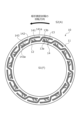
- FIG. 11 is a view showing a sliding surface of a stationary seal ring according to a fifth embodiment of the present invention, as viewed from the axial direction.
- FIG. 11 is a view showing a sliding surface of a stationary seal ring in a modified example of the first embodiment of the present invention, as viewed from the axial direction.
- the mechanical seal shown in Figure 1 is an outside type that seals the sealed fluid F that is trying to leak from the inner diameter side to the outer diameter side of the sliding surface, and the outer space S2 is connected to the atmosphere A.
- the sealed fluid F is a high-pressure liquid
- the atmosphere A is a gas with a lower pressure than the sealed fluid F.
- the first groove portion 141 extends circumferentially from the upstream side of the rotational direction of the rotating seal ring 20 to the downstream side of the rotational direction, i.e., it extends from the upstream side to the downstream side in the relative rotational direction. Note that it is sufficient for the first groove portion 141 to have at least a circumferential component, and it may also have a radial component. Note that the radial direction in this invention is sufficient to include at least a radial component, and similarly, the circumferential direction in this invention is sufficient to include at least a circumferential component.
- the end 141a of the first groove portion 141 overlaps in the circumferential direction with the bent portion 144 between the first groove portion 141 and the second groove portion 142 in the pumping groove 14 on the upstream side in the rotational direction of the rotating seal ring 20.
- being arranged in a position where they overlap when viewed from the circumferential direction is expressed as overlapping in the circumferential direction.
- being arranged in a position where they overlap when viewed from the radial direction is expressed in the present invention as overlapping in the radial direction.
- the bent portion 144 in this embodiment has a curved shape, this is not limited to this and it may have a bent shape.
- the positive pressure generated in the dynamic pressure groove 13 and the pumping groove 14 causes the sliding surfaces 11 and 21 to rise between them, causing the sealed fluid F to flow from the inner space S1.
- the sealed fluid F that has flowed into the sealed fluid F is collected in the pumping groove 14. This prevents the sealed fluid F from leaking into the outer space S2.
- the pumping groove 14 of this embodiment has two types of closed ends on the downstream side: the end 143a of the pumping groove 14 and the outer diameter end 13b of the dynamic pressure groove 13, and since there are more outflow points compared to conventional crank-shaped pumping dimples, the relative negative pressure is large. Therefore, there is less leakage of the sealed fluid F into the outer space S2 side compared to conventional dimples.
- the end 141a of the first groove portion 141 overlaps in the circumferential direction with the bent portion 144 between the first groove portion 141 and the second groove portion 142 in the pumping groove 14 on the upstream side in the rotational direction of the rotating seal ring 20, so that the fluid that flows out from the bent portion 144 to between the sliding surfaces 11, 21 can be efficiently recovered by the action of the positive pressure generated at and near the bent portion 144.
- each first groove portion 141 is formed in an arc shape with the same curvature as the sliding surface 11 and is arranged on the same circumference, the first groove portion 141 can guide the sealed fluid F along the rotational direction.
- the sealed fluid F that flows out between the sliding surfaces 11, 21 from the bent portion 144 in the pumping groove 14 adjacent to the upstream side of the rotational direction of the rotating seal ring 20 can also be easily moved along the rotational direction. As a result, the stationary seal ring 10 can evenly recover the sealed fluid F.
- the dynamic pressure groove 13 is shown to be connected to the third groove portion 143 of the pumping groove 14, but it may be provided in the first groove portion 141 or the second groove portion 142.
- the end 143a of the pumping groove 14 is closed, but the end 143a of the pumping groove 14 may be connected to the internal space S1.
- a pressure generating section may be provided at a location other than the end 143a of the pumping groove 14.
- the shape of the end 143a of the pumping groove 14 can be freely changed.
- the pressure generating portion may be curved to form a convex shape in the extension direction, or may have a tapered shape.
- the shape of the outer diameter end 13b of the dynamic pressure groove 13 can be freely changed.
- the dynamic pressure generating portion may be curved to form a convex shape in the extension direction, or may have a tapered shape.
- a dynamic pressure generating groove may be provided separately from the dynamic pressure groove 13 of this embodiment.
- the pumping groove 14 in this embodiment has been illustrated as having a rectangular cross section, the cross section may be U-shaped, semicircular, triangular, or may be modified as appropriate. The same applies to the dynamic pressure groove 13.
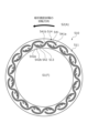
- Example 2 the sliding parts of Example 2 will be described with reference to FIG. 4. Note that descriptions of the same configuration as in Example 1 will be omitted.
- the sliding surface 311 of the stationary seal ring 310 of this embodiment 2 is provided with a plurality of pumping grooves 314 and a plurality of dynamic pressure grooves 313.
- the pumping groove 314 is composed of a first groove portion 341, a second groove portion 342, and a third groove portion 343.
- the second groove portion 342 extends in an arc shape from the end of the first groove portion 341 downstream in the rotational direction of the rotating seal ring 20 toward the inner space S1 so as to form a convex inner diameter side.
- the bend portion 344 between the first groove portion 341 and the second groove portion 342 in the pumping groove 314 is formed at an acute angle compared to the bend portion 144 in Example 1.
- the bend portion 344 is a curved portion in the pumping groove 314, and functions as a pressure generating portion in the pumping groove 314.
- Example 3 the sliding parts of Example 3 will be described with reference to FIG. 5. Note that descriptions of the same configuration as Example 1 will be omitted.
- the sliding surface 411 of the stationary seal ring 410 in this embodiment 3 has multiple pumping grooves 414 and multiple dynamic pressure grooves 413 formed therein.
- the pumping groove 414 is connected to the second groove portion 442 at a position spaced upstream from the end portion 441b, which serves as a pressure generating portion downstream of the relative rotation of the rotating seal ring 20 in the first groove portion 441.
- Example 4 the sliding parts of Example 4 will be described with reference to FIG. 6. Note that descriptions of the same configuration as in Example 1 will be omitted.
- the sliding surface 511 of the stationary seal ring 510 in this embodiment 4 has multiple pumping grooves 514 and multiple dynamic pressure grooves 513 formed therein.
- the pumping groove 514 is composed of a first curved groove portion 541 and a second curved groove portion 542.
- the first curved groove portion 541 is formed in a circular arc shape that is convex toward the outer diameter side with a substantially constant curvature that is smaller than the curvature of the bent portion 144 of the first embodiment.
- the end portion 541 downstream in the rotation direction of the rotating seal ring 20 of the first curved groove portion 541 is connected to the second curved groove portion 542.
- the end portion 541a upstream in the rotation direction of the rotating seal ring 20 of the first curved groove portion 541 is closed.
- the first curved groove portion 541 also has a curved portion 541b that extends from its circumferential center toward the inner diameter side and downstream in the rotational direction of the rotating seal ring 20 toward the second curved groove portion 542. A slight positive pressure is generated in the curved portion 541b. In this way, the curved portion 541b functions as a pressure generating portion in the pumping groove 514.
- the pumping groove 514 of this embodiment suppresses the positive pressure generated in the curved portion 541b compared to the pumping groove 14 of the first embodiment, making it easier to guide the fluid collected in the first curved groove portion 541 to the second curved groove portion 542.
- the second curved groove portion 542 has a shape that is substantially the same as the shape of the first curved groove portion 541, which is inverted radially and circumferentially.
- the end portion 542a of the second curved groove portion 542 downstream in the rotational direction of the rotating seal ring 20 is closed.
- the end portion of the second curved groove portion 542 upstream in the rotational direction of the rotating seal ring 20 is connected to the first curved groove portion 541.
- the second curved groove portion 542 also communicates with two dynamic pressure grooves 513.
- the end 542a of the second curved groove portion 542 of the pumping groove 514 extends toward the downstream side in the direction of rotation and toward the outer diameter side, dynamic pressure can be generated at a position radially close to the outer diameter end 513b of each dynamic pressure groove 513.
- the curved portion 542b functions as a pressure generating portion at the circumferential end portion downstream in the relative direction of rotation of the pumping groove 514.
- Example 5 the sliding parts of Example 5 will be described with reference to FIG. 7. Note that descriptions of the same configuration as in Example 1 will be omitted.
- the mechanical seal to which the stationary seal ring 210 of this embodiment 5 is applied seals the sealed fluid F present on the outer space S12 side of the sliding surfaces 211, 21, and is an inside type in which the inner space S11 is connected to the atmosphere A.
- the sliding surface 211 has multiple pumping grooves 214 and multiple dynamic pressure grooves 213 formed therein.
- the fluid on the leakage space side was described as air, which is a low-pressure gas, but it is not limited to this and may be liquid or high-pressure gas, or a mist-like mixture of liquid and gas.
- the sealed fluid space side has been described as the high pressure side and the leakage space side as the low pressure side, but the sealed fluid space side may be the low pressure side and the leakage space side may be the high pressure side, or the sealed fluid space side and the leakage space side may be at approximately the same pressure.
- the dynamic pressure generating groove and the fluid recovery groove are described as being connected to each other, but this is not limiting, and the dynamic pressure generating groove and the fluid recovery groove may be non-connected.
- the dynamic pressure generating groove 13A and the fluid recovery groove 14A may be non-connected.
Landscapes
- Engineering & Computer Science (AREA)
- General Engineering & Computer Science (AREA)
- Mechanical Engineering (AREA)
- Physics & Mathematics (AREA)
- Fluid Mechanics (AREA)
- Chemical & Material Sciences (AREA)
- Oil, Petroleum & Natural Gas (AREA)
- Mechanical Sealing (AREA)
- Sliding-Contact Bearings (AREA)
Priority Applications (4)
| Application Number | Priority Date | Filing Date | Title |
|---|---|---|---|
| CN202380086078.7A CN120359370A (zh) | 2022-12-26 | 2023-12-25 | 滑动部件 |
| KR1020257021143A KR20250112866A (ko) | 2022-12-26 | 2023-12-25 | 슬라이딩 부품 |
| EP23912085.0A EP4644736A1 (en) | 2022-12-26 | 2023-12-25 | Sliding component |
| JP2024567825A JPWO2024143306A1 (https=) | 2022-12-26 | 2023-12-25 |
Applications Claiming Priority (2)
| Application Number | Priority Date | Filing Date | Title |
|---|---|---|---|
| JP2022-208343 | 2022-12-26 | ||
| JP2022208343 | 2022-12-26 |
Publications (1)
| Publication Number | Publication Date |
|---|---|
| WO2024143306A1 true WO2024143306A1 (ja) | 2024-07-04 |
Family
ID=91718040
Family Applications (1)
| Application Number | Title | Priority Date | Filing Date |
|---|---|---|---|
| PCT/JP2023/046517 Ceased WO2024143306A1 (ja) | 2022-12-26 | 2023-12-25 | 摺動部品 |
Country Status (5)
| Country | Link |
|---|---|
| EP (1) | EP4644736A1 (https=) |
| JP (1) | JPWO2024143306A1 (https=) |
| KR (1) | KR20250112866A (https=) |
| CN (1) | CN120359370A (https=) |
| WO (1) | WO2024143306A1 (https=) |
Citations (4)
| Publication number | Priority date | Publication date | Assignee | Title |
|---|---|---|---|---|
| WO2014050920A1 (ja) * | 2012-09-29 | 2014-04-03 | イーグル工業株式会社 | 摺動部品 |
| WO2020162349A1 (ja) * | 2019-02-04 | 2020-08-13 | イーグル工業株式会社 | 摺動部品 |
| WO2021246371A1 (ja) * | 2020-06-02 | 2021-12-09 | イーグル工業株式会社 | 摺動部品 |
| WO2023199791A1 (ja) * | 2022-04-11 | 2023-10-19 | イーグル工業株式会社 | 摺動部品 |
-
2023
- 2023-12-25 WO PCT/JP2023/046517 patent/WO2024143306A1/ja not_active Ceased
- 2023-12-25 JP JP2024567825A patent/JPWO2024143306A1/ja active Pending
- 2023-12-25 EP EP23912085.0A patent/EP4644736A1/en active Pending
- 2023-12-25 KR KR1020257021143A patent/KR20250112866A/ko active Pending
- 2023-12-25 CN CN202380086078.7A patent/CN120359370A/zh active Pending
Patent Citations (5)
| Publication number | Priority date | Publication date | Assignee | Title |
|---|---|---|---|---|
| WO2014050920A1 (ja) * | 2012-09-29 | 2014-04-03 | イーグル工業株式会社 | 摺動部品 |
| JP6058018B2 (ja) | 2012-09-29 | 2017-01-11 | イーグル工業株式会社 | 摺動部品 |
| WO2020162349A1 (ja) * | 2019-02-04 | 2020-08-13 | イーグル工業株式会社 | 摺動部品 |
| WO2021246371A1 (ja) * | 2020-06-02 | 2021-12-09 | イーグル工業株式会社 | 摺動部品 |
| WO2023199791A1 (ja) * | 2022-04-11 | 2023-10-19 | イーグル工業株式会社 | 摺動部品 |
Non-Patent Citations (1)
| Title |
|---|
| See also references of EP4644736A1 |
Also Published As
| Publication number | Publication date |
|---|---|
| KR20250112866A (ko) | 2025-07-24 |
| JPWO2024143306A1 (https=) | 2024-07-04 |
| CN120359370A (zh) | 2025-07-22 |
| EP4644736A1 (en) | 2025-11-05 |
Similar Documents
| Publication | Publication Date | Title |
|---|---|---|
| CN113439167B (zh) | 滑动部件 | |
| KR102651943B1 (ko) | 슬라이딩 부품 | |
| JP7538920B2 (ja) | 摺動部品 | |
| JPWO2020166589A1 (ja) | 摺動部品 | |
| JP7307102B2 (ja) | 摺動部品 | |
| CN113348308B (zh) | 滑动部件 | |
| CN113661330B (zh) | 滑动部件 | |
| JP7618671B2 (ja) | 摺動部品 | |
| CN113454353B (zh) | 滑动部件 | |
| JP7749888B2 (ja) | 摺動部品 | |
| JP7804695B2 (ja) | 摺動要素 | |
| JP7520473B2 (ja) | 摺動部品 | |
| WO2024143306A1 (ja) | 摺動部品 | |
| JP7804762B2 (ja) | 摺動部品 | |
| JP7555688B2 (ja) | 摺動部品 | |
| WO2024143304A1 (ja) | 摺動部品 | |
| WO2024143307A1 (ja) | 摺動部品 | |
| WO2025150435A1 (ja) | 摺動部品 | |
| WO2024143303A1 (ja) | 摺動部品 | |
| JP7767584B2 (ja) | 摺動部品 | |
| JP7804775B2 (ja) | 摺動部品 | |
| JP7767616B2 (ja) | 摺動部品 | |
| WO2025239228A1 (ja) | 摺動部品 | |
| JP7846066B2 (ja) | 摺動部品 | |
| WO2026004745A1 (ja) | 一対の摺動部品 |
Legal Events
| Date | Code | Title | Description |
|---|---|---|---|
| 121 | Ep: the epo has been informed by wipo that ep was designated in this application |
Ref document number: 23912085 Country of ref document: EP Kind code of ref document: A1 |
|
| WWE | Wipo information: entry into national phase |
Ref document number: 2024567825 Country of ref document: JP |
|
| WWE | Wipo information: entry into national phase |
Ref document number: 202380086078.7 Country of ref document: CN |
|
| WWE | Wipo information: entry into national phase |
Ref document number: 1020257021143 Country of ref document: KR |
|
| WWP | Wipo information: published in national office |
Ref document number: 202380086078.7 Country of ref document: CN |
|
| WWP | Wipo information: published in national office |
Ref document number: 1020257021143 Country of ref document: KR |
|
| WWE | Wipo information: entry into national phase |
Ref document number: 2023912085 Country of ref document: EP |
|
| NENP | Non-entry into the national phase |
Ref country code: DE |
|
| ENP | Entry into the national phase |
Ref document number: 2023912085 Country of ref document: EP Effective date: 20250728 |
|
| ENP | Entry into the national phase |
Ref document number: 2023912085 Country of ref document: EP Effective date: 20250728 |
|
| WWP | Wipo information: published in national office |
Ref document number: 2023912085 Country of ref document: EP |