WO2024143165A1 - 送風装置 - Google Patents
送風装置 Download PDFInfo
- Publication number
- WO2024143165A1 WO2024143165A1 PCT/JP2023/045981 JP2023045981W WO2024143165A1 WO 2024143165 A1 WO2024143165 A1 WO 2024143165A1 JP 2023045981 W JP2023045981 W JP 2023045981W WO 2024143165 A1 WO2024143165 A1 WO 2024143165A1
- Authority
- WO
- WIPO (PCT)
- Prior art keywords
- airflow
- guide portion
- air
- area
- guide
- Prior art date
- Legal status (The legal status is an assumption and is not a legal conclusion. Google has not performed a legal analysis and makes no representation as to the accuracy of the status listed.)
- Ceased
Links
Images


Classifications
-
- F—MECHANICAL ENGINEERING; LIGHTING; HEATING; WEAPONS; BLASTING
- F04—POSITIVE - DISPLACEMENT MACHINES FOR LIQUIDS; PUMPS FOR LIQUIDS OR ELASTIC FLUIDS
- F04D—NON-POSITIVE-DISPLACEMENT PUMPS
- F04D25/00—Pumping installations or systems
- F04D25/02—Units comprising pumps and their driving means
- F04D25/08—Units comprising pumps and their driving means the working fluid being air, e.g. for ventilation
- F04D25/10—Units comprising pumps and their driving means the working fluid being air, e.g. for ventilation the unit having provisions for automatically changing direction of output air
-
- F—MECHANICAL ENGINEERING; LIGHTING; HEATING; WEAPONS; BLASTING
- F24—HEATING; RANGES; VENTILATING
- F24F—AIR-CONDITIONING; AIR-HUMIDIFICATION; VENTILATION; USE OF AIR CURRENTS FOR SCREENING
- F24F13/00—Details common to, or for air-conditioning, air-humidification, ventilation or use of air currents for screening
- F24F13/02—Ducting arrangements
- F24F13/06—Outlets for directing or distributing air into rooms or spaces, e.g. ceiling air diffuser
-
- F—MECHANICAL ENGINEERING; LIGHTING; HEATING; WEAPONS; BLASTING
- F24—HEATING; RANGES; VENTILATING
- F24F—AIR-CONDITIONING; AIR-HUMIDIFICATION; VENTILATION; USE OF AIR CURRENTS FOR SCREENING
- F24F7/00—Ventilation
- F24F7/04—Ventilation with ducting systems, e.g. by double walls; with natural circulation
- F24F7/06—Ventilation with ducting systems, e.g. by double walls; with natural circulation with forced air circulation, e.g. by fan positioning of a ventilator in or against a conduit
-
- F—MECHANICAL ENGINEERING; LIGHTING; HEATING; WEAPONS; BLASTING
- F24—HEATING; RANGES; VENTILATING
- F24F—AIR-CONDITIONING; AIR-HUMIDIFICATION; VENTILATION; USE OF AIR CURRENTS FOR SCREENING
- F24F2130/00—Control inputs relating to environmental factors not covered by group F24F2110/00
- F24F2130/10—Weather information or forecasts
Definitions
- the present invention relates to a blower device.
- the air blowing device described in Patent Document 1 includes a blower, an outlet, a duct, and an airflow deflection door.
- the blower blows out air.
- the outlet blows out air into the interior space of the vehicle, which is the target space.
- the duct connects the outlet and the blower.
- the airflow deflection door is disposed in the air flow path within the duct. The airflow deflection door can generate two airflows with different flow speeds within the duct.
- the airflow deflection door may block the blowing outlet, excessively reducing the air volume. Also, when maintaining the airflow volume, it is difficult to blow air in the direction desired by the designer. In other words, it is difficult to blow air in the direction desired by the designer while suppressing the reduction in air volume.
- the present invention was made in consideration of the above problems, and aims to provide a blower that can blow air in the direction desired by the designer while minimizing the reduction in air volume.
- the blower device includes a blower section, a housing, and a change section.
- the blower section blows air.
- the housing houses the blower section.
- the change section changes the direction of the wind.
- the change section has a first guide section and a second guide section.
- the first guide section guides the wind to the outside of the housing.
- the second guide section is located upstream of the first guide section in the flow of the wind, and guides the wind blown from the blower section.
- the first guide section is inclined relative to the second guide section.
- the air blower of the present invention can blow air in the direction desired by the designer while minimizing the reduction in air volume.
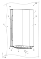
- FIG. 1 is a perspective view of a blower device according to an embodiment of the present invention, as viewed obliquely from the front.
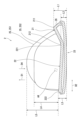
- FIG. 2 is a cross-sectional view of the blower device shown in FIG. 1 .
- 4 is a diagram showing a cross section of a louver of the blower device according to the embodiment of the present invention.
- FIG. 4A and 4B are diagrams illustrating louvers of a blower device according to an embodiment of the present invention.
- 11 is a diagram showing a louver when an opening of the air blower device according to the embodiment of the present invention is opened.
- FIG. 11 is a diagram showing a louver when closing an opening of a blower device according to an embodiment of the present invention.
- 11A and 11B are diagrams illustrating a louver of a blower device according to a comparative example.
- 4 shows an airflow blown out from an opening of a blower device according to a comparative example.
- 10 is a diagram showing a schematic diagram of the strength of the airflow blown out from the blower device according to the comparative example.
- FIG. 4A and 4B are diagrams illustrating louvers of the blower device according to the embodiment.
- 5A and 5B are diagrams illustrating air currents blown out from an opening of the blower device according to the embodiment.
- 5A and 5B are diagrams illustrating the strength of the airflow blown out from the blower device according to the embodiment.
- the drawings show the X-axis, Y-axis, and Z-axis that indicate a three-dimensional orthogonal coordinate system.
- the X-axis and Y-axis are parallel to the horizontal direction
- the Z-axis is parallel to the vertical direction.
- the blower device 100 includes a housing 1 and a louver 2.
- the blower device 100 may further include an operation unit (not shown).
- the operation unit receives instructions from a user. Specifically, the user issues instructions for each operation mode, such as air direction control and air volume control, via operation buttons (not shown) on the operation unit.
- the operation unit may receive operations from an external device. The external device controls the operation of each component of the blower device 100.
- the housing 1 is a hollow member.
- the housing 1 has, for example, a box shape.
- the housing 1 is installed on an installation surface G of a room.
- the installation surface G is, for example, a wall surface of the room.
- the material of the housing 1 includes, for example, sheet metal or synthetic resin. However, the material of the housing 1 is not particularly limited.
- the housing 1 includes a front cover 11, a rear cover 12, and a pair of side panels 13.
- the housing 1 has an opening H and a first suction port 14.
- the first suction ports 14 are disposed on each of the pair of side panels 13.
- the first suction ports 14 draw air into the interior of the housing 1. Specifically, the first suction ports 14 draw air from the side panel 13 side of the housing 1 into the interior of the housing 1.
- FIG. 2 is a cross-sectional view of the blower device 100 shown in Fig. 1.
- the blower device 100 further includes an air cleaning filter 15 and a fan 3.
- the air purifying filter 15 is, for example, a HEPA (High Efficiency Particulate Air) filter made of nonwoven fabric formed into a paper-like material. However, there are no particular limitations on the type of air purifying filter 15.
- the air purifying filter 15 purifies the air sucked in from the first suction port 14.
- the air purifying filter 15 is housed inside the housing 1.
- the first storage section 131 houses the fan 3.
- the first storage section 131 has a second intake port 132 and a first outlet port 133.
- the first storage section 131 is connected to the duct 141 on the first outlet port 133 side.
- the second intake port 132 draws in air that has passed through the air purification filter 15.
- the first outlet port 133 blows air into the duct 141.
- the duct 141 guides the airflow f2 discharged by the fan 3.
- the duct 141 is located on the rear cover 12 side.
- the airflow f2 indicates the flow of wind moving in the direction from the first housing section 131 toward the duct 141.
- the duct 141 has a second opening 145.
- the second opening 145 is located downstream of the airflow f2 from the first outlet 133.
- the second opening 145 includes a second outlet 142.
- the second outlet 142 blows air toward the opening H.
- the second outlet 142 is through which air blown by the fan 3 passes.
- the second outlet 142 is an example of an "opening".
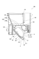
- FIG 3 is a diagram showing a cross section of the louver 2.
- the louver 2 is rotatable. As shown in Figure 2, the angle of the louver 2 can be changed to an angle at which it intersects with the airflow f2.
- the louver 2 covers the opening H. In other words, the louver 2 can block the opening H.
- the louver 2 has a first guide portion 21, a second guide portion 22, a cover portion 23, and a rotation axis AX.
- the rotation axis AX changes the angle of the louver 2. Specifically, the rotation axis AX rotates the first guide portion 21, the second guide portion 22, and the cover portion 23.
- the second guide section 22 guides the air blown from the fan 3. Specifically, as shown in FIG. 2, the second guide section 22 guides the airflow f3 that has passed through the second outlet 142 to the first guide section 21.
- the airflow f3 indicates the flow of air moving from the second outlet 142 to the opening H.
- the second guide section 22 is located upstream of the airflow f3 from the first guide section 21.
- the first guide section 21 guides the air to the outside of the housing 1. Specifically, as shown in FIG. 2, the first guide section 21 guides the airflow f3 that has passed through the second air outlet 142 to the outside of the housing 1. More specifically, the first guide section 21 guides the airflow f3 that has been guided to the second guide section 22 to the outside of the housing 1.
- the first guide section 21 is located downstream of the airflow f3 from the second guide section 22.
- the first guide section 21 is inclined relative to the second guide section 22. Therefore, the airflow f3 guided to the second guide section 22 can be guided in accordance with the inclination of the first guide section 21. As a result, the airflow f sent out from the blower device 100 can be blown in the direction intended by the designer while suppressing a reduction in the air volume.
- the direction of the airflow f can be changed by the first guide portion 21, and the airflow f can be guided toward the wall surface opposite the installation surface G.
- the opening degree of the opening H can be made larger compared to a blower device that does not have the first guide portion 21. Therefore, it is also possible to prevent a decrease in the momentum of the airflow f blown out of the blower device 100. In other words, a sufficient amount of air can be secured while moving the airflow f in the direction desired by the designer.
- the first guide portion 21 also has a first connection portion 212 and a first end portion 211.
- the first connection portion 212 is an end portion that is connected to the second guide portion 22.
- the first connection portion 212 is located upstream of the first end portion 211 in the airflow f3.
- the first end 211 is the end of the first guide portion 21 located downstream of the airflow f3 from the first connection portion 212.
- the first end 211 is the end located on the first direction D1 side from the first connection portion 212.
- the first direction D1 indicates the direction from the second guide portion 22 toward the rotation axis AX. Therefore, the first guide portion 21 can be tilted from the first end 211 toward the first connection portion 212. As a result, the direction of the airflow f3 guided to the second guide portion 22 can be easily changed.
- the engraved portion 26 is an end of the first guide portion 21 that is located downstream of the airflow f3 from the first end portion 211.
- the engraved portion 26 is fixed to the lid portion 23.
- the second guide portion 22 also has a second connection portion 221 and a second end portion 222.
- the second end portion 222 is an end portion of the second guide portion 22 located upstream of the airflow f3 from the second connection portion 221.
- the second end portion 222 is an end portion located on the other side of the second direction D2.
- the second direction D2 is a direction intersecting the first direction D1.
- the second direction D2 indicates a direction along the direction from the second end portion 222 toward the second connection portion 221.
- the second end portion 222 is fixed to the lid portion 23.
- the second connection portion 221 is an end portion that is connected to the first guide portion 21. Specifically, the second connection portion 221 is an end portion that is connected to the first connection portion 212. The second connection portion 221 is located downstream of the airflow f3 from the second end portion 222. The second connection portion 221 is located on one side of the second direction D2.
- the lid portion 23 closes the opening H.
- the lid portion 23 also opens the opening H.
- the lid portion 23 closes the opening H by rotating in one direction around the rotation axis AX.
- the lid portion 23 opens the opening H by rotating in the other direction around the rotation axis AX.
- the lid portion 23 faces the first guide portion 21 and the second guide portion 22. Specifically, the lid portion 23 is located in a fourth direction D4, which is the opposite direction to the first direction D1, relative to the first guide portion 21. In addition, the lid portion 23 is located in the fourth direction D4 relative to the second guide portion 22.
- the lid portion 23 is spaced a predetermined distance from the first end 211.
- the lid portion 23 is spaced a predetermined distance from the first connection portion 212.
- the first distance L1 from the lid portion 23 to the first end 211 in the first direction D1 is longer than the second distance L2 from the lid portion 23 to the first connection portion 212 in the first direction D1. Therefore, the first guide portion 21 can be further tilted from the first end 211 toward the first connection portion 212. As a result, the direction of the airflow f3 guided to the second guide portion 22 can be changed even more significantly.
- louver 2 will be described in more detail with reference to Figures 3 and 4.
- Figure 4 shows the louver 2.
- the louver 2 has a plurality of plate portions 25.
- the plurality of plate portions 25 guide the airflow f3 blown out from the second outlet 142 to the second guide portion 22.
- the plurality of plate portions 25 extend in the first direction D1 from the second guide portion 22.
- the plurality of plate portions 25 extend in the first direction D1 beyond the rotation axis AX.
- the multiple plate portions 25 also extend in a direction from the first guide portion 21 toward the second guide portion 22. This allows the airflow f3 guided to the second guide portion 22 to be straightened. As a result, the airflow f3 can be easily guided along the inclination of the first guide portion 21.
- the second plate portion 252 is disposed between the pair of first plate portions 251.
- the second plate portion 252 straightens the airflow f3 moving between the first plate portion 251 and the second plate portion 252.
- the length of the second plate portion 252 in the first direction D1 is length L4.
- multiple second plate portions 252 may be arranged between a pair of first plate portions 251.
- the multiple second plate portions 252 are arranged along the third direction D3.
- the second plate portions 252 rectify the airflow f3 moving between adjacent second plate portions 252 and adjacent first plate portions 251.
- the pair of first plate portions 251 rectify the airflow f3 moving between the first plate portion 251 and the second plate portion 252.
- the length of the first plate portion 251 in the first direction D1 is length L5.
- Length L5 is longer than length L4.
- the length of the first plate portion 251 in the first direction D1 is longer than the length of the second plate portion 252 in the first direction D1. Therefore, it is possible to prevent the airflow f3 from moving beyond the first plate portion 251. In other words, it is easy to move the airflow f3 so that it passes between the first plate portion 251 and the second plate portion 252. As a result, the airflow f3 moving between the first plate portion 251 and the second plate portion 252 can be easily rectified.
- the housing 1 further has a third guide portion 143.
- the second opening 145 has a fourth guide portion 144 and a lattice portion 146.
- the fourth guide portion 144 is disposed inside the housing 1.
- the fourth guide portion 144 protrudes from the duct 141 toward the opening H.
- the fourth guide portion 144 guides the air that has passed through the second opening 145 to the second guide portion 22.
- the fourth guide portion 144 extends in a direction intersecting the first direction D1.
- the fourth guide portion 144 is inclined in a direction from the second opening 145 toward the rotation axis AX. Therefore, the direction of the airflow that has passed through the second opening 145 can be changed in accordance with the inclination of the fourth guide portion 144. Therefore, it is easy to make the airflow f3 reach the second guide portion 22.
- the second guide portion 22 can easily guide the airflow that has passed through the second opening 145.
- the fourth guide portion 144 can prevent the airflow f3 that has passed through the second opening 145 from being blown out of the opening H without being guided by the second guide portion 22.
- the lattice portion 146 prevents a part of the user's body from entering the inside of the duct 141 beyond the second air outlet 142.
- the lattice portion 146 includes a first lattice 146a and a second lattice 146b.
- the first lattice 146a extends in a direction from the front cover 11 toward the rear cover 12.
- the first lattice 146a intersects with the direction of the airflow f2.
- the first lattice 146a has a plurality of through holes through which the airflow f2 passes.
- One end of the first lattice 146a is connected to the third guide portion 143.
- One end of the first lattice 146a is the end on the front cover 11 side.
- the other end of the first lattice 146a is connected to the second lattice 146b.
- the other end of the first lattice 146a is the end on the rear cover 12 side.
- the second lattice 146b is inclined from the first lattice 146a toward the fourth guide section 144.
- the second lattice 146b intersects with the direction of the airflow f2.
- the second lattice 146b has multiple through holes through which the airflow f2 passes.
- the airflow guided by the fourth guide section 144 passes through the through holes of the second lattice 146b.
- the second lattice 146b allows the airflow guided by the fourth guide section 144 to pass toward the second guide section 22, while restricting any part of the user's body from entering the inside of the duct 141.
- One end of the second lattice 146b is connected to the other end of the first lattice 146a.
- One end of the second lattice 146b is the end on the duct 141 side.
- the other end of the second lattice 146b is connected to the fourth guide section 144.
- the other end of the second lattice 146b is the end on the opening H side.
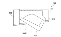
- FIG. 7A shows louvers 502 of a blower device 500 according to a comparative example.
- FIG. 7B shows airflow blown out from openings 500H of a blower device 500 according to a comparative example.
- FIG. 7C is a schematic diagram showing the strength of the airflow blown out from a blower device 500 according to a comparative example.
- the blower device 500 according to the comparative example is installed on the wall of a room, similar to the blower device 100 according to this embodiment.
- the configuration of the blower device 500 according to the comparative example differs from the louver 2 of the blower device 100 according to this embodiment in that the louver 502 is different.
- the louvers 502 of the blower 500 become thicker toward the opening 500H.
- the louvers 502 are inclined toward the opening 500H. Because the louvers 502 do not have the first guide portion 21, the opening angle of the louvers 502 becomes excessively small when the airflow is directed toward the wall surface opposite the wall surface on which the blower 500 is installed.
- the louvers 502 guide the airflow.
- the louvers 502 of the comparative example guide the airflow toward the front cover 511.
- the blower device 500 of the comparative example does not have the third guide portion 143 of the blower device 100 of the present embodiment, and therefore the airflow is disturbed between the louver 502 and the front cover 511. Therefore, the blower device 500 of the comparative example cannot efficiently guide the airflow to the louver 502.
- the airflow reaches the first area A51, the second area A52, the third area A53, the fourth area A54, the fifth area A55, and the sixth area A56.
- the third area A53 is an area indicated by hatching with dots having the second highest density after the second area A52.
- the third area A53 is an area in which the airflow speed and volume are greater than the fourth area A54 and the sixth area A56.
- airflow moves at a third airflow speed and a third airflow volume.
- the third airflow speed is smaller than the second airflow speed.
- the third airflow volume is smaller than the second airflow volume.
- the fourth area A54 is the area indicated by the least densely hatched dots.
- the fourth area A54 is an area in which the airflow speed and volume are smaller than the first area A51, the second area A52, the third area A53, and the fifth area A55.
- airflow moves at a fourth airflow speed and a fourth airflow volume.
- the fourth airflow speed is smaller than the third airflow speed.
- the fourth airflow volume is smaller than the third airflow volume.
- the fourth area A54 reaches the floor of the room.
- the fifth area A55 is an area indicated by hatching with dots having the second highest density after the second area A52.
- the fifth area A55 shows the airflow blown out from between the louvers 502 and the rear cover 512.
- the fifth area A55 is an area where the airflow has a higher wind speed and volume than the fourth area A54 and the sixth area A56.
- the fifth area A55 is an area where the airflow has approximately the same wind speed and volume as the third area A53. In other words, in the fifth area A55, an airflow with a third wind speed and third volume moves.
- the sixth area A56 is an area indicated by hatching with dots at the lowest density.
- the sixth area A56 is an area in which the airflow speed and volume are smaller than those of the first area A51, the second area A52, the third area A53, and the fifth area A55.
- the sixth area A56 is an area in which the airflow speed and volume are approximately the same as those of the fourth area A54. In other words, in the sixth area A56, airflow moves at the fourth speed and fourth volume.
- the blower device 500 of the comparative example does not have the fourth guide portion 144 of the blower device 100 of the present embodiment. Therefore, the blower device 500 of the comparative example cannot efficiently guide the airflow to the louver 502. Specifically, since it does not have the fourth guide portion 144 of the blower device 100 of the present embodiment, the airflow is also blown out from between the louver 502 and the rear cover 512. Therefore, the blower device 500 of the comparative example blows out the airflow guided by the louver 502 and the airflow blown out from between the louver 502 and the rear cover 512. In other words, it is difficult to guide the airflow in the direction desired by the designer while maintaining the air volume.
- FIG. 8A shows the louver 2 of the blower device 100 according to this embodiment.
- FIG. 8B shows the airflow blown out from the opening H of the blower device 100 according to this embodiment.
- FIG. 8C is a schematic diagram showing the strength of the airflow blown out from the blower device 100 according to this embodiment.
- the angle of the louver 2 shown in FIG. 8A is the same as that of the louver 502 shown in FIG. 7A.
- the blower device 100 according to this embodiment has the third guide portion 143, and therefore can guide the airflow to the first guide portion 21. This prevents the airflow from entering between the third guide portion 143 and the front cover 11 and causing turbulence. Therefore, the blower device 100 according to this embodiment can guide the airflow to the louver 2 more efficiently than the blower device 500 of the comparative example.
- the blower device 100 according to this embodiment has the fourth guide portion 144, it can guide the airflow to the second guide portion 22. Specifically, it can prevent the airflow from being blown out from between the louver 2 and the rear cover 12.
- the blower device 100 according to this embodiment can guide the airflow to the louver 2 more efficiently than the blower device 500 of the comparative example. Therefore, it is possible to easily guide the airflow in the direction desired by the designer while maintaining the air volume.
- the airflow reaches the first area A1, the second area A2, the third area A3, and the fourth area A4.
- the first area A1 is an area indicated by dot hatching.
- the dot hatching in the first area A1 is the densest.
- the first area A1 is an area in which the airflow speed and volume are greater than those in the second area A2, the third area A3, and the fourth area A4. In the first area A1, the airflow guided by the louvers 2 moves at a first speed and a first volume.
- the third area A3 is an area indicated by hatching with dots having the second highest density after the second area A52.
- the third area A3 is an area in which the airflow speed and volume are greater than those of the fourth area A4. In the third area A3, airflow moves at a third speed and a third volume. The airflow in the third area A3 reaches the wall of the room.
- the fourth area A4 is the area indicated by the least densely hatched dots.
- the fourth area A4 is an area in which the airflow speed and volume are smaller than those of the first area A1, the second area A2, and the third area A3.
- airflow moves at a fourth speed and a fourth volume.
- the wall of the fourth area A4 reaches the wall of the room.
- the blower device 100 of this embodiment can make the airflow reach the location desired by the designer. Furthermore, because the airflow with the third wind speed and the third wind volume reaches the wall surface, the blower device 100 of this embodiment can prevent a reduction in the air volume and wind speed.
- the air blower 100 shown in embodiment 1 may have, for example, a dehumidification function and a humidification function.
- the air blower 100 draws in air around the air blower 100, removes moisture contained in the drawn-in air, and blows out the air.
- the air blower 100 can dry clothes by blowing dehumidified air (wind) onto the clothes.
- the air blower 100 increases the moisture contained in the air drawn in by the air blower 100 and blows out the air.
- the present invention provides a blower device and has industrial applicability.
Landscapes
- Engineering & Computer Science (AREA)
- Mechanical Engineering (AREA)
- General Engineering & Computer Science (AREA)
- Chemical & Material Sciences (AREA)
- Combustion & Propulsion (AREA)
- Feeding Of Articles To Conveyors (AREA)
- Structures Of Non-Positive Displacement Pumps (AREA)
Priority Applications (1)
| Application Number | Priority Date | Filing Date | Title |
|---|---|---|---|
| JP2024567718A JPWO2024143165A1 (https=) | 2022-12-27 | 2023-12-21 |
Applications Claiming Priority (2)
| Application Number | Priority Date | Filing Date | Title |
|---|---|---|---|
| JP2022209716 | 2022-12-27 | ||
| JP2022-209716 | 2022-12-27 |
Publications (1)
| Publication Number | Publication Date |
|---|---|
| WO2024143165A1 true WO2024143165A1 (ja) | 2024-07-04 |
Family
ID=91717663
Family Applications (1)
| Application Number | Title | Priority Date | Filing Date |
|---|---|---|---|
| PCT/JP2023/045981 Ceased WO2024143165A1 (ja) | 2022-12-27 | 2023-12-21 | 送風装置 |
Country Status (3)
| Country | Link |
|---|---|
| JP (1) | JPWO2024143165A1 (https=) |
| TW (1) | TW202426832A (https=) |
| WO (1) | WO2024143165A1 (https=) |
Citations (2)
| Publication number | Priority date | Publication date | Assignee | Title |
|---|---|---|---|---|
| JPH05280804A (ja) * | 1992-03-31 | 1993-10-29 | Sanyo Electric Co Ltd | 空気調和機 |
| JP2000249394A (ja) * | 1999-02-25 | 2000-09-12 | Sharp Corp | 空気調和機 |
-
2023
- 2023-11-17 TW TW112144659A patent/TW202426832A/zh unknown
- 2023-12-21 WO PCT/JP2023/045981 patent/WO2024143165A1/ja not_active Ceased
- 2023-12-21 JP JP2024567718A patent/JPWO2024143165A1/ja active Pending
Patent Citations (2)
| Publication number | Priority date | Publication date | Assignee | Title |
|---|---|---|---|---|
| JPH05280804A (ja) * | 1992-03-31 | 1993-10-29 | Sanyo Electric Co Ltd | 空気調和機 |
| JP2000249394A (ja) * | 1999-02-25 | 2000-09-12 | Sharp Corp | 空気調和機 |
Also Published As
| Publication number | Publication date |
|---|---|
| TW202426832A (zh) | 2024-07-01 |
| JPWO2024143165A1 (https=) | 2024-07-04 |
Similar Documents
| Publication | Publication Date | Title |
|---|---|---|
| JP5121878B2 (ja) | 空気清浄機 | |
| KR102231096B1 (ko) | 공기청정기 | |
| JP4867746B2 (ja) | 空気調和機 | |
| CN202283365U (zh) | 空气调节机和离子产生单元 | |
| JP2009024595A (ja) | 遠心ファン及びこれを用いた空気調和機 | |
| CN102753897A (zh) | 风扇、循环器、微粒扩散装置及空气循环方法 | |
| KR20170057028A (ko) | 송풍장치 및 이를 포함하는 공기청정기 | |
| WO2024143165A1 (ja) | 送風装置 | |
| JP5809021B2 (ja) | 送風装置およびイオン発生機 | |
| JP2009018221A (ja) | 空気清浄機 | |
| JP6957308B2 (ja) | 空調システム | |
| JP5012410B2 (ja) | 空気調和機 | |
| JP2004347264A (ja) | 送風装置、ルーバ及びそれを備えた空気調節装置 | |
| JP6467623B2 (ja) | 空気清浄装置 | |
| KR102946698B1 (ko) | 공기 청정기 | |
| JP2011094928A (ja) | 加湿機付きイオン発生機 | |
| JP2004353977A (ja) | イオン発生素子の取付構造及びこれを用いた送風構造並びに空調装置及び空調システム | |
| JP4123876B2 (ja) | 遠心式送風機 | |
| JP5851796B2 (ja) | イオン発生機 | |
| JP5397335B2 (ja) | 空気調和機 | |
| JP4774609B2 (ja) | 多翼ファン | |
| CN113614454A (zh) | 送风装置 | |
| WO2023181535A1 (ja) | 気流形成システム | |
| CN110462303A (zh) | 摆叶及送风装置 | |
| JP2005282927A (ja) | 熱交換形換気扇 |
Legal Events
| Date | Code | Title | Description |
|---|---|---|---|
| 121 | Ep: the epo has been informed by wipo that ep was designated in this application |
Ref document number: 23911945 Country of ref document: EP Kind code of ref document: A1 |
|
| WWE | Wipo information: entry into national phase |
Ref document number: 2024567718 Country of ref document: JP |
|
| NENP | Non-entry into the national phase |
Ref country code: DE |
|
| 122 | Ep: pct application non-entry in european phase |
Ref document number: 23911945 Country of ref document: EP Kind code of ref document: A1 |