WO2024142829A1 - 光学系、光学機器及び光学系の製造方法 - Google Patents
光学系、光学機器及び光学系の製造方法 Download PDFInfo
- Publication number
- WO2024142829A1 WO2024142829A1 PCT/JP2023/043829 JP2023043829W WO2024142829A1 WO 2024142829 A1 WO2024142829 A1 WO 2024142829A1 JP 2023043829 W JP2023043829 W JP 2023043829W WO 2024142829 A1 WO2024142829 A1 WO 2024142829A1
- Authority
- WO
- WIPO (PCT)
- Prior art keywords
- lens
- optical system
- negative meniscus
- meniscus lens
- negative
- Prior art date
- Legal status (The legal status is an assumption and is not a legal conclusion. Google has not performed a legal analysis and makes no representation as to the accuracy of the status listed.)
- Ceased
Links
Images




Classifications
-
- G—PHYSICS
- G02—OPTICS
- G02B—OPTICAL ELEMENTS, SYSTEMS OR APPARATUS
- G02B13/00—Optical objectives specially designed for the purposes specified below
- G02B13/04—Reversed telephoto objectives
-
- G—PHYSICS
- G02—OPTICS
- G02B—OPTICAL ELEMENTS, SYSTEMS OR APPARATUS
- G02B13/00—Optical objectives specially designed for the purposes specified below
- G02B13/18—Optical objectives specially designed for the purposes specified below with lenses having one or more non-spherical faces, e.g. for reducing geometrical aberration
Definitions
- the present invention relates to an optical system, an optical device, and a method for manufacturing an optical system.
- Patent Document 1 In the past, compact optical systems with wide angles of view have been proposed (see, for example, Patent Document 1). However, Patent Document 1 had an issue in that there was a demand for a system that was both compact and lightweight while still providing good optical performance.
- the optical system according to the first aspect of the present invention comprises, in order from the object side, a first negative meniscus lens having negative refractive power with a convex surface facing the object side, a second negative meniscus lens having negative refractive power with a convex surface facing the object side, a third biconcave negative lens having negative refractive power, and at least one lens, and satisfies the following condition: 90.0° ⁇ ⁇ 0.10 ⁇ R12/(-fL1) ⁇ 0.80 however, ⁇ : half angle of view of the optical system fL1: focal length of the first negative meniscus lens R12: radius of curvature of the lens surface of the first negative meniscus lens on the image side
- the optical system according to the second aspect of the present invention comprises, in order from the object side, a first negative meniscus lens having negative refractive power with a convex surface facing the object side, a second negative meniscus lens having negative refractive power with a convex surface facing the object side, a third biconcave negative lens having negative refractive power, and at least one lens, and satisfies the following condition: 90.0° ⁇ ⁇ 1.80 ⁇ R12/D12 ⁇ 3.00 however, ⁇ : half angle of view of the optical system D12: on-axis air spacing between the first negative meniscus lens and the second negative meniscus lens R12: radius of curvature of the lens surface of the first negative meniscus lens on the image surface side
- FIG. 2 is a cross-sectional view showing a lens configuration of the optical system according to the first example when focusing on an object at infinity.
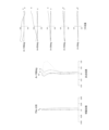
- 5A to 5C are diagrams illustrating various aberrations when the optical system according to the first example is focused on an object at infinity.
- FIG. 11 is a cross-sectional view showing a lens configuration of an optical system according to a second example when focusing on an object at infinity.
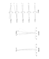
- 13A to 13C are diagrams illustrating various aberrations when the optical system according to the second example is focused on an object at infinity.
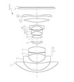
- FIG. 11 is a cross-sectional view showing a lens configuration of an optical system according to Example 3 when focusing on an object at infinity.
- optical system OL Accordingly, it is desirable for the optical system OL according to the second embodiment to satisfy the following conditional expression (3).
- conditional formula (3) In addition, if the upper limit of conditional formula (3) is exceeded, it is undesirable because the correction of the curvature of field and astigmatism becomes insufficient. In order to ensure the effect of conditional formula (3), it is more preferable to set the upper limit of conditional formula (3) to 2.80, 2.65, and even more preferable to set it to 2.50.
- R12 radius of curvature of the lens surface of the first negative meniscus lens L1 on the image side
- ⁇ 12 effective diameter of the lens surface of the first negative meniscus lens L1 on the image side
- Conditional formula (4) specifies the ratio of the effective diameter of the lens surface on the image side of the first negative meniscus lens L1 to the radius of curvature of the lens surface on the image side of the first negative meniscus lens L1.
- optical system OL Accordingly, it is desirable for the optical system OL according to this embodiment to satisfy the following conditional expression (5).
- R22 radius of curvature of the lens surface on the image side of the second negative meniscus lens L2
- ⁇ 22 effective diameter of the lens surface on the image side of the second negative meniscus lens L2
- Conditional formula (5) specifies the ratio of the effective diameter of the lens surface on the image side of the second negative meniscus lens L2 to the radius of curvature of the lens surface on the image side of the second negative meniscus lens L2.
- Conditional formula (6) specifies the ratio of the radius of curvature of the lens surface on the image side of the first negative meniscus lens L1 to the thickness on the optical axis of the first negative meniscus lens L1. By satisfying this conditional formula (6), it is possible to achieve both a small and lightweight optical system OL and good optical performance. If the lower limit of conditional formula (6) is exceeded, it is undesirable because it becomes difficult to correct the curvature of field and astigmatism. In order to ensure the effect of conditional formula (6), it is more preferable to set the lower limit of conditional formula (6) to 8.00, 8.50, or even 8.80.
- conditional formula (6) In addition, if the upper limit of conditional formula (6) is exceeded, the entire optical system OL becomes large, and if the radius of curvature of the lens surface on the object side of the first negative meniscus lens L1 is reduced to alleviate this effect, it is undesirable because it becomes difficult to correct the astigmatism and curvature of field. In order to ensure the effect of conditional expression (6), it is more preferable to set the upper limit of conditional expression (6) to 10.50, 10.00, or even 9.50.
- R11 radius of curvature of the object side lens surface of the first negative meniscus lens L1
- R12 radius of curvature of the image side lens surface of the first negative meniscus lens L1
- conditional formula (8) In addition, if the upper limit of conditional formula (8) is exceeded, it is not preferable because it is difficult to correct the spherical aberration. In order to ensure the effect of conditional formula (8), it is more preferable to set the upper limit of conditional formula (8) to 0.75, 0.70, or even 0.65.
- Conditional expression (9) specifies the ratio of the radius of curvature of the lens surface on the image side of the second negative meniscus lens L2 to the thickness on the optical axis of the second negative meniscus lens L2. By satisfying this conditional expression (9), it is possible to achieve both a small and lightweight optical system OL and good optical performance. If the lower limit of conditional expression (9) is exceeded, it is undesirable because it becomes difficult to correct the curvature of field and astigmatism. In order to ensure the effect of conditional expression (9), it is more preferable to set the lower limit of conditional expression (9) to 7.00, 7.50, or even 8.00.
- conditional expression (9) In addition, if the upper limit of conditional expression (9) is exceeded, the entire optical system OL becomes large, and if the radius of curvature of the lens surface on the object side of the second negative meniscus lens L2 is reduced to alleviate this effect, it is undesirable because it becomes difficult to correct the astigmatism and curvature of field. In order to ensure the effect of conditional expression (9), it is more preferable to set the upper limit value of conditional expression (9) to 11.50, 11.00, 10.50, or even 10.00.
- Ymax maximum image height of the optical system OL TL: total optical length (air equivalent length) when the optical system OL is focused at infinity
- optical system OL Accordingly, it is desirable for the optical system OL according to this embodiment to satisfy the following conditional expression (13).
- nd1 refractive index of the medium of the first negative meniscus lens L1 with respect to the d-line
- nd2 refractive index of the medium of the second negative meniscus lens L2 with respect to the d-line
- Conditional formula (13) specifies the average value of the refractive index for the d-line of the medium of the first negative meniscus lens L1 and the second negative meniscus lens L2. By satisfying this conditional formula (13), it is possible to achieve both a small and lightweight optical system OL and good optical performance. If the lower limit of conditional formula (13) is exceeded, the refractive index for the d-line of the medium of the first negative meniscus lens L1 and the second negative meniscus lens L2 becomes low, which is undesirable because it becomes difficult to correct the curvature of field and astigmatism. In order to ensure the effect of conditional formula (13), it is more preferable to set the lower limit of conditional formula (13) to 1.78, and even more preferably 1.80.
- conditional formula (13) In addition, if the upper limit of conditional formula (13) is exceeded, it is undesirable because an appropriate Petzval sum cannot be obtained and it becomes difficult to correct astigmatism. In order to ensure the effect of conditional expression (13), it is more preferable to set the upper limit of conditional expression (13) to 1.94, 1.92, or even 1.90.
- optical system OL Accordingly, it is desirable for the optical system OL according to this embodiment to satisfy the following conditional expression (14).
- ⁇ d1 Abbe number of the medium of the first negative meniscus lens L1 at the d line
- ⁇ d2 Abbe number of the medium of the second negative meniscus lens L2 at the d line
- Conditional formula (14) specifies the average value of the Abbe number for the d-line of the medium of the first negative meniscus lens L1 and the second negative meniscus lens L2. By satisfying this conditional formula (14), it is possible to achieve both a small size and a light weight of the optical system OL and good optical performance. If the lower limit of conditional formula (14) is exceeded, the chromatic aberration generated in the first negative meniscus lens L1 and the second negative meniscus lens L2 cannot be corrected by other lenses, which is undesirable. In order to ensure the effect of conditional formula (14), it is more preferable to set the lower limit of conditional formula (14) to 31.5, 32.5, 34.0, and further 34.5.
- conditional formula (14) In addition, if the upper limit of conditional formula (14) is exceeded, the Abbe number of the medium of the first negative meniscus lens L1 and the second negative meniscus lens L2 becomes small, which is undesirable because it becomes difficult to correct the curvature of field and astigmatism. In order to ensure the effect of conditional expression (14), it is more preferable to set the upper limit of conditional expression (14) to 43.0, 41.5, 40.0, or even 38.0.
- Conditional formula (16) specifies the ratio of the focal length of the entire system in an infinity focused state to the focal length of the second cemented lens CLb from the object side among the cemented lenses closer to the image plane than the aperture stop (aperture stop S). By satisfying this conditional formula (16), it is possible to achieve both a compact and lightweight optical system OL and good optical performance. If the lower limit of conditional formula (16) is exceeded, it is difficult to correct the chromatic aberration of magnification, which is undesirable. In order to ensure the effect of conditional formula (16), it is more preferable to set the lower limit of conditional formula (16) to -0.25, -0.20, -0.15, or -0.10.
- each lens surface may be coated with an anti-reflection coating that has high transmittance over a wide wavelength range to reduce flare and ghosting and achieve high-contrast optical performance.
Landscapes
- Physics & Mathematics (AREA)
- General Physics & Mathematics (AREA)
- Optics & Photonics (AREA)
- Lenses (AREA)
Abstract
Description
90.0° < ω
0.10 < R12/(-fL1) < 0.80
但し、
ω:前記光学系の半画角
fL1:前記第一負メニスカスレンズの焦点距離
R12:前記第一負メニスカスレンズの像面側のレンズ面の曲率半径
90.0° < ω
1.80 < R12/D12 < 3.00
但し、
ω:前記光学系の半画角
D12:前記第一負メニスカスレンズと前記第二負メニスカスレンズとの間の軸上空気間隔
R12:前記第一負メニスカスレンズの像面側のレンズ面の曲率半径
90.0° < ω
0.10 < R12/(-fL1) < 0.80
但し、
ω:前記光学系の半画角
fL1:前記第一負メニスカスレンズの焦点距離
R12:前記第一負メニスカスレンズの像面側のレンズ面の曲率半径
90.0° < ω
1.80 < R12/D12 < 3.00
但し、
ω:前記光学系の半画角
D12:前記第一負メニスカスレンズと前記第二負メニスカスレンズとの間の軸上空気間隔
R12:前記第一負メニスカスレンズの像面側のレンズ面の曲率半径
第1の実施形態に係る光学系OLは、図1に示すように、物体側から順に、物体側に凸面を向けた負の屈折力を有する第一負メニスカスレンズL1と、物体側に凸面を向けた負の屈折力を有する第二負メニスカスレンズL2と、負の屈折力を有する第三両凹負レンズL3と、少なくとも1枚のレンズとを有して構成されている。このように構成することにより、光学系OLの小型化・軽量化と良好な光学性能とを両立させることができる。
但し、
ω:光学系OLの半画角
但し、
fL1:第一負メニスカスレンズL1の焦点距離
R12:第一負メニスカスレンズL1の像面側のレンズ面の曲率半径
第2の実施形態に係る光学系OLは、図1に示すように、物体側から順に、物体側に凸面を向けた負の屈折力を有する第一負メニスカスレンズL1と、物体側に凸面を向けた負の屈折力を有する第二負メニスカスレンズL2と、負の屈折力を有する第三両凹負レンズL3と、少なくとも1枚のレンズとを有して構成されている。このように構成することにより、光学系OLの小型化・軽量化と良好な光学性能とを両立させることができる。
但し、
D12:第一負メニスカスレンズL1と第二負メニスカスレンズL2との間の軸上空気間隔
R12:第一負メニスカスレンズL1の像面側のレンズ面の曲率半径
また、第1の実施形態及び第2の実施形態(以下「本実施形態」と呼ぶ)に係る光学系OLは、以下に示す条件式(4)を満足することが望ましい。
但し、
R12:第一負メニスカスレンズL1の像面側のレンズ面の曲率半径
φ12:第一負メニスカスレンズL1の像面側のレンズ面の有効径
但し、
R22:第二負メニスカスレンズL2の像面側のレンズ面の曲率半径
φ22:第二負メニスカスレンズL2の像面側のレンズ面の有効径
但し、
DL1:第一負メニスカスレンズL1の光軸上の厚さ
R12:第一負メニスカスレンズL1の像面側のレンズ面の曲率半径
但し、
R11:第一負メニスカスレンズL1の物体側のレンズ面の曲率半径
R12:第一負メニスカスレンズL1の像面側のレンズ面の曲率半径
但し、
fL2:第二負メニスカスレンズL2の焦点距離
R22:第二負メニスカスレンズL2の像面側のレンズ面の曲率半径
但し、
DL2:第二負メニスカスレンズL2の光軸上の厚さ
R22:第二負メニスカスレンズL2の像面側のレンズ面の曲率半径
但し、
R21:第二負メニスカスレンズL2の物体側のレンズ面の曲率半径
R22:第二負メニスカスレンズL2の像面側のレンズ面の曲率半径
但し、
D23:第二負メニスカスレンズL2と第三両凹負レンズL3との間の軸上空気間隔
R22:第二負メニスカスレンズL2の像面側のレンズ面の曲率半径
但し、
Ymax:光学系OLの最大像高
TL:光学系OLの無限遠合焦状態における光学全長(空気換算長)
但し、
nd1:第一負メニスカスレンズL1の媒質のd線に対する屈折率
nd2:第二負メニスカスレンズL2の媒質のd線に対する屈折率
但し、
νd1:第一負メニスカスレンズL1の媒質のd線に対するアッベ数
νd2:第二負メニスカスレンズL2の媒質のd線に対するアッベ数
但し、
fa:絞り(開口絞りS)より像面側の接合レンズのうち、最も物体側に配置された接合レンズCLaの焦点距離
f:光学系OLの無限遠合焦状態における全系の焦点距離
但し、
fb:絞り(開口絞りS)より像面側の接合レンズのうち、物体側から2番目の接合レンズCLbの焦点距離
f:光学系OLの無限遠合焦状態における全系の焦点距離
+A4×y4+A6×y6+A8×y8+A10×y10+A12×y12 (a)
図1は、第1実施例に係る光学系OL1の構成を示している。この光学系OL1は、物体側から順に、物体側に凸面を向けたメニスカス形状の負レンズ(第一負メニスカスレンズ)L1、物体側に凸面を向けたメニスカス形状の負レンズ(第二負メニスカスレンズ)L2、物体側のレンズ面及び像面側のレンズ面が非球面形状に形成された両凹形状の負レンズ(第三両凹負レンズ)L3、両凸形状の正レンズL4、物体側のレンズ面及び像面側のレンズ面が非球面形状に形成された両凸形状の正レンズL5、両凸形状の正レンズL6と両凹形状の負レンズL7とを接合した接合負レンズCLa、物体側に凹面を向けたメニスカス形状の正レンズL8と物体側に凹面を向けたメニスカス形状の負レンズL9とを接合した接合負レンズCLb、物体側のレンズ面及び像面側のレンズ面が非球面形状に形成された物体側に凸面を向けたメニスカス形状の正レンズL10(Ln-1)、及び、物体側のレンズ面及び像面側のレンズ面が非球面形状に形成された両凸形状の正レンズL11(Ln)で構成されている。なお、正レンズL10(Ln-1)の物体側のレンズ面及び像面側のレンズ面、並びに、正レンズL11(Ln)の物体側のレンズ面及び像面側のレンズ面は曲率反転のある非球面である。
[全体諸元]
f = 10.184
FNo = 4.08
ω = 108.1
Ymax = 21.630
TL(空気換算長) = 75.604
Bf(空気換算長) = 10.185
[レンズデータ]
m r d nd νd ip
物面 ∞
1 38.8086 2.0000 1.846660 23.80
2 18.1489 7.5089
3 34.8073 1.2000 1.804000 46.60
4 10.7528 7.9956
5* -24.4955 3.4882 1.516800 64.13
6* 17.7105 1.3476
7 26.8728 6.2548 1.846660 23.80
8 -41.7098 6.2175
9 ∞ 0.1000 開口絞りS
10* 16.1802 2.2961 1.516800 64.13
11* -15.4891 1.4138
12 39.9385 3.8403 1.516800 64.13
13 -11.1383 1.0000 1.846660 23.80
14 63.9809 3.3773
15 -72.2609 5.2297 1.516800 64.13
16 -8.3676 1.0000 1.804000 46.60
17 -22.2128 0.1010
18* 28.8319 3.0944 1.536497 55.98 5.0
19* 35.9760 3.3991 4.7
20* 36.7332 4.5549 1.536497 55.98 14.3
21* -925.9246 8.6297 14.4
22 ∞ 1.6000 1.516800 64.13
23 ∞ 0.5000
像面 ∞
[非球面データ]
m K A4 A6 A8 A10 A12
5 0.382 1.953e-05 1.097e-07 1.814e-10 -4.272e-12 0.000e-00
6 1.963 6.745e-05 6.621e-07 -4.961e-09 5.269e-11 0.000e-00
10 0.000 1.872e-05 1.106e-07 -6.243e-09 3.857e-10 0.000e-00
11 0.000 5.263e-05 -2.331e-07 2.395e-08 -2.410e-10 0.000e-00
18 -0.695 -1.261e-04 4.100e-07 -7.949e-09 4.776e-11 0.000e-00
19 1.410 -1.184e-04 2.742e-07 -4.418e-09 3.123e-11 0.000e-00
20 0.000 3.542e-05 -4.594e-07 1.939e-09 -3.017e-12 0.000e-00
21 0.000 9.243e-05 -4.616e-07 1.417e-09 -2.044e-12 0.000e-00
図3は、第2実施例に係る光学系OL2の構成を示している。この光学系OL2は、物体側から順に、物体側に凸面を向けたメニスカス形状の負レンズ(第一負メニスカスレンズ)L1、物体側に凸面を向けたメニスカス形状の負レンズ(第二負メニスカスレンズ)L2、像面側のレンズ面に非球面が形成された両凹形状の負レンズ(第三両凹負レンズ)L3、両凸形状の正レンズL4、物体側のレンズ面及び像面側のレンズ面が非球面形状に形成された両凸形状の正レンズL5、両凸形状の正レンズL6と両凹形状の負レンズL7とを接合した接合負レンズCLa、両凸形状の正レンズL8と物体側に凹面を向けたメニスカス形状の負レンズL9とを接合した接合正レンズCLb、物体側のレンズ面及び像面側のレンズ面が非球面形状に形成された両凸形状の正レンズL10(Ln-1)、及び、物体側のレンズ面及び像面側のレンズ面が非球面形状に形成された物体側に凸面を向けたメニスカス形状の正レンズL11(Ln)で構成されている。なお、負レンズL3は、ガラス製レンズ本体の像面側のレンズ面に樹脂層が設けられて非球面が形成されている複合型のレンズである。また、正レンズL10(Ln-1)の像面側のレンズ面、並びに、正レンズL11(Ln)の物体側のレンズ面及び像面側のレンズ面は曲率反転のある非球面である。
[全体諸元]
f = 10.800
FNo = 4.31
ω = 108.2
Ymax = 21.630
TL(空気換算長) = 75.681
Bf(空気換算長) = 13.589
[レンズデータ]
m r d nd νd ip
物面 ∞
1 38.4930 2.0000 1.846660 23.80
2 18.1994 7.7453
3 31.3266 1.2000 1.804000 46.60
4 10.1212 7.4845
5 -28.2828 1.8745 1.516800 64.13
6 13.5367 0.3000 1.517417 52.43
7* 16.0189 1.1415
8 23.1082 4.1597 1.846660 23.80
9 -1133.8574 6.4898
10 ∞ 0.1000 開口絞りS
11* 13.8921 5.2227 1.516800 64.13
12* -17.8409 2.4747
13 15.8353 5.4988 1.516800 64.13
14 -9.4885 1.0000 1.850260 32.35
15 23.3720 0.9227
16 53.5359 5.6247 1.516800 64.13
17 -10.7038 1.0000 1.850260 32.35
18 -37.2536 1.5633
19* 28.3105 4.1472 1.536497 55.98
20* -73.6320 0.5924 11.4
21* 38.4645 1.5494 1.536497 55.98 15.3
22* 37.9324 12.0345 13.1
23 ∞ 1.6000 1.516800 64.13
24 ∞ 0.5000
像面 ∞
[非球面データ]
m K A4 A6 A8 A10 A12
7 0.000 5.864e-05 4.236e-07 1.341e-09 4.009e-11 0.000e-00
11 0.000 -2.348e-06 4.229e-07 -1.794e-08 4.158e-10 0.000e-00
12 0.000 4.274e-05 5.241e-07 -1.154e-08 2.520e-10 0.000e-00
19 0.000 -4.102e-05 -5.807e-08 6.132e-10 -1.064e-12 0.000e-00
20 0.000 -3.901e-05 3.288e-07 2.259e-10 -1.272e-12 0.000e-00
21 0.000 6.497e-06 -1.613e-07 9.567e-10 -1.754e-12 0.000e-00
22 0.000 8.431e-05 -7.162e-07 2.374e-09 -3.132e-12 0.000e-00
図5は、第3実施例に係る光学系OL3の構成を示している。この光学系OL3は、物体側から順に、物体側に凸面を向けたメニスカス形状の負レンズ(第一負メニスカスレンズ)L1、物体側に凸面を向けたメニスカス形状の負レンズ(第二負メニスカスレンズ)L2、両凹形状の負レンズ(第三両凹負レンズ)L3、両凸形状の正レンズL4、物体側のレンズ面及び像面側のレンズ面が非球面形状に形成された物体側に凸面を向けたメニスカス形状の正レンズL5、両凸形状の正レンズL6、両凸形状の正レンズL7と両凹形状の負レンズL8とを接合した接合負レンズCLa、両凸形状の正レンズL9と物体側に凹面を向けたメニスカス形状の負レンズL10とを接合した接合負レンズCLb、物体側のレンズ面及び像面側のレンズ面が非球面形状に形成された両凸形状の正レンズL11(Ln-1)、及び、物体側のレンズ面及び像面側のレンズ面が非球面形状に形成された両凸形状の正レンズL12(Ln)で構成されている。なお、正レンズL11(Ln-1)の物体側のレンズ面、並びに、正レンズL12(Ln)の物体側のレンズ面及び像面側のレンズ面は曲率反転のある非球面である。
[全体諸元]
f = 10.320
FNo = 4.10
ω = 108.2
Ymax = 21.630
TL(空気換算長) = 80.453
Bf(空気換算長) = 9.555
[レンズデータ]
m r d nd νd ip
物面 ∞
1 38.1536 2.0000 2.000690 25.46
2 18.7162 8.8900
3 64.8953 1.2000 1.772500 49.62
4 11.6510 10.7371
5 -22.3206 1.1044 1.772500 49.62
6 81.7597 0.1000
7 56.6242 7.6127 1.850260 32.35
8 -25.9653 3.6583
9* 12.0383 1.9489 1.647690 33.72
10* 14.5775 4.1023
11 ∞ 1.3075 開口絞りS
12 20.1343 3.3377 1.563840 60.71
13 -14.2563 0.1559
14 21.0384 4.5506 1.487490 70.32
15 -10.4332 1.0000 1.850260 32.35
16 16.6449 1.0524
17 47.3014 4.7935 1.487490 70.32
18 -9.9926 1.0000 1.850260 32.35
19 -39.8171 3.8396
20* 46.6429 4.3398 1.536497 55.98 10.2
21* -89.6813 2.4988
22* 87.3093 1.6690 1.536497 55.98 7.1
23* -330.4666 8.0000 8.7
24 ∞ 1.6000 1.516800 64.13
25 ∞ 0.5000
像面 ∞
[非球面データ]
m K A4 A6 A8 A10 A12
9 0.000 -9.573e-06 1.487e-07 -3.046e-08 -3.922e-10 1.654e-22
10 0.000 8.932e-05 2.650e-06 -9.717e-08 5.604e-10 -7.248e-23
20 0.000 -3.454e-06 2.602e-07 -2.664e-09 7.746e-12 -1.048e-14
21 0.000 -2.187e-05 1.976e-07 1.281e-09 -1.957e-11 5.433e-14
22 0.000 1.165e-04 -1.656e-06 7.400e-09 -1.612e-11 1.530e-14
23 0.000 2.077e-04 -2.071e-06 9.243e-09 -2.025e-11 1.649e-14
第1実施例~第3実施例における条件式(1)~(16)の対応値を以下の表7に示す。
(1)ω
(2)R12/(-fL1)
(3)R12/D12
(4)φ12/R12
(5)φ22/R22
(6)R12/DL1
(7)(R12+R11)/(R12-R11)
(8)R22/(-fL2)
(9)R22/DL2
(10)(R22+R21)/(R22-R21)
(11)R22/D23
(12)TL/Ymax
(13)(nd1+nd2)/2
(14)(νd1+νd2)/2
(15)f/fa
(16)f/fb
第1実施例 第2実施例 第3実施例
fL1 -42.137 -42.702 -38.704
fL2 -19.793 -19.078 -18.565
φ12 32.666 32.759 33.696
φ22 19.353 18.262 20.987
fa -34.945 -32.903 -17.591
fb -228.098 533.836 -258.987
(1) 108.1 108.2 108.2
(2) 0.431 0.426 0.484
(3) 2.417 2.350 2.105
(4) 1.800 1.800 1.800
(5) 1.800 1.804 1.801
(6) 9.074 9.100 9.358
(7) -2.757 -2.794 -2.926
(8) 0.543 0.531 0.628
(9) 8.961 8.434 9.709
(10) -1.894 -1.955 -1.438
(11) 1.345 1.352 1.085
(12) 3.495 3.499 3.720
(13) 1.825 1.825 1.887
(14) 35.200 35.200 37.540
(15) -0.291 -0.328 -0.587
(16) -0.045 0.020 -0.040
L1 第一負メニスカスレンズ L2 第二負メニスカスレンズ
L3 第三両凹負レンズ S 開口絞り(絞り)
Claims (19)
- 物体側から順に、物体側に凸面を向けた負の屈折力を有する第一負メニスカスレンズと、物体側に凸面を向けた負の屈折力を有する第二負メニスカスレンズと、負の屈折力を有する第三両凹負レンズと、少なくとも1枚のレンズとからなり、
次式の条件を満足する光学系。
90.0° < ω
0.10 < R12/(-fL1) < 0.80
但し、
ω:前記光学系の半画角
fL1:前記第一負メニスカスレンズの焦点距離
R12:前記第一負メニスカスレンズの像面側のレンズ面の曲率半径 - 物体側から順に、物体側に凸面を向けた負の屈折力を有する第一負メニスカスレンズと、物体側に凸面を向けた負の屈折力を有する第二負メニスカスレンズと、負の屈折力を有する第三両凹負レンズと、少なくとも1枚のレンズとからなり、
次式の条件を満足する光学系。
90.0° < ω
1.80 < R12/D12 < 3.00
但し、
ω:前記光学系の半画角
D12:前記第一負メニスカスレンズと前記第二負メニスカスレンズとの間の軸上空気間隔
R12:前記第一負メニスカスレンズの像面側のレンズ面の曲率半径 - 次式の条件を満足する請求項1または2に記載の光学系。
φ12/R12 < 1.90
但し、
R12:前記第一負メニスカスレンズの像面側のレンズ面の曲率半径
φ12:前記第一負メニスカスレンズの像面側のレンズ面の有効径 - 次式の条件を満足する請求項1~3のいずれか一項に記載の光学系。
φ22/R22 < 1.90
但し、
R22:前記第二負メニスカスレンズの像面側のレンズ面の曲率半径
φ22:前記第二負メニスカスレンズの像面側のレンズ面の有効径 - 次式の条件を満足する請求項1~4のいずれか一項に記載の光学系。
7.50 < R12/DL1 < 11.00
但し、
DL1:前記第一負メニスカスレンズの光軸上の厚さ
R12:前記第一負メニスカスレンズの像面側のレンズ面の曲率半径 - 次式の条件を満足する請求項1~5のいずれか一項に記載の光学系。
-3.50 < (R12+R11)/(R12-R11) < -2.00
但し、
R11:前記第一負メニスカスレンズの物体側のレンズ面の曲率半径
R12:前記第一負メニスカスレンズの像面側のレンズ面の曲率半径 - 次式の条件を満足する請求項1~6のいずれか一項に記載の光学系。
0.20 < R22/(-fL2) < 0.80
但し、
fL2:前記第二負メニスカスレンズの焦点距離
R22:前記第二負メニスカスレンズの像面側のレンズ面の曲率半径 - 次式の条件を満足する請求項1~7のいずれか一項に記載の光学系。
6.50 < R22/DL2 < 12.00
但し、
DL2:前記第二負メニスカスレンズの光軸上の厚さ
R22:前記第二負メニスカスレンズの像面側のレンズ面の曲率半径 - 次式の条件を満足する請求項1~8のいずれか一項に記載の光学系。
-2.50 < (R22+R21)/(R22-R21) < -1.00
但し、
R21:前記第二負メニスカスレンズの物体側のレンズ面の曲率半径
R22:前記第二負メニスカスレンズの像面側のレンズ面の曲率半径 - 次式の条件を満足する請求項1~9のいずれか一項に記載の光学系。
0.80 < R22/D23 < 2.00
但し、
D23:前記第二負メニスカスレンズと前記第三両凹負レンズとの間の軸上空気間隔
R22:前記第二負メニスカスレンズの像面側のレンズ面の曲率半径 - 次式の条件を満足する請求項1~10のいずれか一項に記載の光学系。
2.00 < TL/Ymax < 5.00
但し、
Ymax:前記光学系の最大像高
TL:前記光学系の無限遠合焦状態における光学全長 - 次式の条件を満足する請求項1~11のいずれか一項に記載の光学系。
1.75 < (nd1+nd2)/2 < 1.95
但し、
nd1:前記第一負メニスカスレンズの媒質のd線に対する屈折率
nd2:前記第二負メニスカスレンズの媒質のd線に対する屈折率 - 次式の条件を満足する請求項1~12のいずれか一項に記載の光学系。
30.0 < (νd1+νd2)/2 < 45.0
但し、
νd1:前記第一負メニスカスレンズの媒質のd線に対するアッベ数
νd2:前記第二負メニスカスレンズの媒質のd線に対するアッベ数 - 絞りと、前記絞りの物体側又は像面側に隣接して配置された正レンズと、を有する請求項1~13のいずれか一項に記載の光学系。
- 絞りを有し、
次式の条件を満足する請求項1~14のいずれか一項に記載の光学系。
-0.80 < f/fa < 0.10
但し、
fa:前記絞りより像面側の接合レンズのうち、最も物体側に配置された接合レンズの焦点距離
f:前記光学系の無限遠合焦状態における全系の焦点距離 - 絞りを有し、
次式の条件を満足する請求項1~15のいずれか一項に記載の光学系。
-0.30 < f/fb < 0.30
但し、
fb:前記絞りより像面側の接合レンズのうち、物体側から2番目の接合レンズの焦点距離
f:前記光学系の無限遠合焦状態における全系の焦点距離 - 請求項1~16のいずれか一項に記載の光学系を備える光学機器。
- 物体側から順に、物体側に凸面を向けた負の屈折力を有する第一負メニスカスレンズと、物体側に凸面を向けた負の屈折力を有する第二負メニスカスレンズと、負の屈折力を有する第三両凹負レンズと、少なくとも1枚のレンズとからなる光学系の製造方法であって、
次式の条件を満足するように配置する光学系の製造方法。
90.0° < ω
0.10 < R12/(-fL1) < 0.80
但し、
ω:前記光学系の半画角
fL1:前記第一負メニスカスレンズの焦点距離
R12:前記第一負メニスカスレンズの像面側のレンズ面の曲率半径 - 物体側から順に、物体側に凸面を向けた負の屈折力を有する第一負メニスカスレンズと、物体側に凸面を向けた負の屈折力を有する第二負メニスカスレンズと、負の屈折力を有する第三両凹負レンズと、少なくとも1枚のレンズとからなる光学系の製造方法であって、
次式の条件を満足するように配置する光学系の製造方法。
90.0° < ω
1.80 < R12/D12 < 3.00
但し、
ω:前記光学系の半画角
D12:前記第一負メニスカスレンズと前記第二負メニスカスレンズとの間の軸上空気間隔
R12:前記第一負メニスカスレンズの像面側のレンズ面の曲率半径
Priority Applications (2)
| Application Number | Priority Date | Filing Date | Title |
|---|---|---|---|
| JP2024567389A JPWO2024142829A5 (ja) | 2023-12-07 | 光学系及び光学機器 | |
| CN202380087904.XA CN120359446A (zh) | 2022-12-26 | 2023-12-07 | 光学系统、光学设备以及光学系统的制造方法 |
Applications Claiming Priority (2)
| Application Number | Priority Date | Filing Date | Title |
|---|---|---|---|
| JP2022-208569 | 2022-12-26 | ||
| JP2022208569 | 2022-12-26 |
Publications (1)
| Publication Number | Publication Date |
|---|---|
| WO2024142829A1 true WO2024142829A1 (ja) | 2024-07-04 |
Family
ID=91717268
Family Applications (1)
| Application Number | Title | Priority Date | Filing Date |
|---|---|---|---|
| PCT/JP2023/043829 Ceased WO2024142829A1 (ja) | 2022-12-26 | 2023-12-07 | 光学系、光学機器及び光学系の製造方法 |
Country Status (2)
| Country | Link |
|---|---|
| CN (1) | CN120359446A (ja) |
| WO (1) | WO2024142829A1 (ja) |
Cited By (2)
| Publication number | Priority date | Publication date | Assignee | Title |
|---|---|---|---|---|
| CN119781138A (zh) * | 2024-12-25 | 2025-04-08 | 佛山市灵觉科技有限公司 | 一种便携大视场眼底相机光学系统 |
| CN120276129A (zh) * | 2025-06-11 | 2025-07-08 | 苏州莱能士光电科技股份有限公司 | 一种低畸变大靶面大通光高解析力的智能交通镜头 |
Citations (5)
| Publication number | Priority date | Publication date | Assignee | Title |
|---|---|---|---|---|
| JP2016191790A (ja) * | 2015-03-31 | 2016-11-10 | 富士フイルム株式会社 | 撮像レンズおよび撮像装置 |
| JP2017015967A (ja) * | 2015-07-02 | 2017-01-19 | Hoya株式会社 | 撮像レンズ系 |
| WO2018189818A1 (ja) * | 2017-04-11 | 2018-10-18 | エスゼット ディージェイアイ テクノロジー カンパニー リミテッド | レンズ系、撮像装置、移動体及びシステム |
| CN111929861A (zh) * | 2020-09-16 | 2020-11-13 | 厦门力鼎光电股份有限公司 | 一种高清鱼眼镜头 |
| CN113933960A (zh) * | 2021-09-28 | 2022-01-14 | 江西晶超光学有限公司 | 光学镜头、摄像模组、电子设备及汽车 |
-
2023
- 2023-12-07 CN CN202380087904.XA patent/CN120359446A/zh active Pending
- 2023-12-07 WO PCT/JP2023/043829 patent/WO2024142829A1/ja not_active Ceased
Patent Citations (5)
| Publication number | Priority date | Publication date | Assignee | Title |
|---|---|---|---|---|
| JP2016191790A (ja) * | 2015-03-31 | 2016-11-10 | 富士フイルム株式会社 | 撮像レンズおよび撮像装置 |
| JP2017015967A (ja) * | 2015-07-02 | 2017-01-19 | Hoya株式会社 | 撮像レンズ系 |
| WO2018189818A1 (ja) * | 2017-04-11 | 2018-10-18 | エスゼット ディージェイアイ テクノロジー カンパニー リミテッド | レンズ系、撮像装置、移動体及びシステム |
| CN111929861A (zh) * | 2020-09-16 | 2020-11-13 | 厦门力鼎光电股份有限公司 | 一种高清鱼眼镜头 |
| CN113933960A (zh) * | 2021-09-28 | 2022-01-14 | 江西晶超光学有限公司 | 光学镜头、摄像模组、电子设备及汽车 |
Cited By (2)
| Publication number | Priority date | Publication date | Assignee | Title |
|---|---|---|---|---|
| CN119781138A (zh) * | 2024-12-25 | 2025-04-08 | 佛山市灵觉科技有限公司 | 一种便携大视场眼底相机光学系统 |
| CN120276129A (zh) * | 2025-06-11 | 2025-07-08 | 苏州莱能士光电科技股份有限公司 | 一种低畸变大靶面大通光高解析力的智能交通镜头 |
Also Published As
| Publication number | Publication date |
|---|---|
| CN120359446A (zh) | 2025-07-22 |
| JPWO2024142829A1 (ja) | 2024-07-04 |
Similar Documents
| Publication | Publication Date | Title |
|---|---|---|
| CN102037388B (zh) | 变焦透镜、具有其的光学设备及变焦透镜的制造方法 | |
| CN110832376A (zh) | 变倍光学系统、光学装置以及变倍光学系统的制造方法 | |
| CN111492287B (zh) | 光学系统以及光学设备 | |
| CN110573924A (zh) | 变倍光学系统、光学装置和制造变倍光学系统的方法 | |
| CN111095070B (zh) | 变倍光学系统、光学装置以及变倍光学系统的制造方法 | |
| JP2017156428A (ja) | 変倍光学系、光学機器及び変倍光学系の製造方法 | |
| JP7627444B2 (ja) | 光学系及び光学機器 | |
| CN120359446A (zh) | 光学系统、光学设备以及光学系统的制造方法 | |
| CN111095071B (zh) | 变倍光学系统、光学装置以及变倍光学系统的制造方法 | |
| JP6938845B2 (ja) | 光学系および光学機器 | |
| CN110546544A (zh) | 变倍光学系统、光学装置和制造变倍光学系统的方法 | |
| CN115244444B (zh) | 光学系统及光学设备 | |
| CN107615130B (zh) | 变倍光学系统以及光学设备 | |
| CN113348397B (zh) | 变倍光学系统以及光学设备 | |
| CN104769477B (zh) | 可变放大率光学系统、光学装置以及可变放大率光学系统的生产方法 | |
| JP2025052870A (ja) | 光学系、光学機器、および光学系の製造方法 | |
| WO2015163368A1 (ja) | 変倍光学系、光学装置、変倍光学系の製造方法 | |
| CN104919354B (zh) | 可变放大率光学系统、光学装置,和用于可变放大率光学系统的生产方法 | |
| JP6627915B2 (ja) | 変倍光学系及び光学機器 | |
| JP7576231B2 (ja) | 光学系及び光学機器 | |
| CN104755986B (zh) | 可变放大率光学系统、光学装置,和用于可变放大率光学系统的生产方法 | |
| WO2014069446A1 (ja) | 変倍光学系、光学装置、変倍光学系の製造方法 | |
| JP6451074B2 (ja) | 変倍光学系、光学装置、変倍光学系の製造方法 | |
| CN113056694B (zh) | 变倍光学系统以及光学设备 | |
| WO2024203170A1 (ja) | 光学系、光学機器及び光学系の製造方法 |
Legal Events
| Date | Code | Title | Description |
|---|---|---|---|
| 121 | Ep: the epo has been informed by wipo that ep was designated in this application |
Ref document number: 23911610 Country of ref document: EP Kind code of ref document: A1 |
|
| WWE | Wipo information: entry into national phase |
Ref document number: 2024567389 Country of ref document: JP |
|
| WWE | Wipo information: entry into national phase |
Ref document number: 202380087904.X Country of ref document: CN |
|
| WWP | Wipo information: published in national office |
Ref document number: 202380087904.X Country of ref document: CN |
|
| NENP | Non-entry into the national phase |
Ref country code: DE |
|
| 122 | Ep: pct application non-entry in european phase |
Ref document number: 23911610 Country of ref document: EP Kind code of ref document: A1 |