WO2024135423A1 - 情報処理装置、情報処理方法、プログラムおよび情報処理システム - Google Patents
情報処理装置、情報処理方法、プログラムおよび情報処理システム Download PDFInfo
- Publication number
- WO2024135423A1 WO2024135423A1 PCT/JP2023/044118 JP2023044118W WO2024135423A1 WO 2024135423 A1 WO2024135423 A1 WO 2024135423A1 JP 2023044118 W JP2023044118 W JP 2023044118W WO 2024135423 A1 WO2024135423 A1 WO 2024135423A1
- Authority
- WO
- WIPO (PCT)
- Prior art keywords
- detection
- unit
- explanation
- information
- information processing
- Prior art date
- Legal status (The legal status is an assumption and is not a legal conclusion. Google has not performed a legal analysis and makes no representation as to the accuracy of the status listed.)
- Ceased
Links
Images


Classifications
-
- G—PHYSICS
- G06—COMPUTING OR CALCULATING; COUNTING
- G06N—COMPUTING ARRANGEMENTS BASED ON SPECIFIC COMPUTATIONAL MODELS
- G06N3/00—Computing arrangements based on biological models
- G06N3/02—Neural networks
- G06N3/04—Architecture, e.g. interconnection topology
- G06N3/0464—Convolutional networks [CNN, ConvNet]
-
- G—PHYSICS
- G06—COMPUTING OR CALCULATING; COUNTING
- G06N—COMPUTING ARRANGEMENTS BASED ON SPECIFIC COMPUTATIONAL MODELS
- G06N5/00—Computing arrangements using knowledge-based models
- G06N5/04—Inference or reasoning models
- G06N5/045—Explanation of inference; Explainable artificial intelligence [XAI]; Interpretable artificial intelligence
-
- G—PHYSICS
- G06—COMPUTING OR CALCULATING; COUNTING
- G06T—IMAGE DATA PROCESSING OR GENERATION, IN GENERAL
- G06T7/00—Image analysis
-
- G—PHYSICS
- G06—COMPUTING OR CALCULATING; COUNTING
- G06V—IMAGE OR VIDEO RECOGNITION OR UNDERSTANDING
- G06V10/00—Arrangements for image or video recognition or understanding
- G06V10/70—Arrangements for image or video recognition or understanding using pattern recognition or machine learning
- G06V10/764—Arrangements for image or video recognition or understanding using pattern recognition or machine learning using classification, e.g. of video objects
Definitions
- the present invention relates to an information processing device, an information processing method, a program, and an information processing system.
- Patent Document 1 divides an image using a pre-set method, performs anomaly detection, and displays an integrated explanation of each anomaly detection result for the divided image.
- the present invention has been made in consideration of the above-mentioned problems, and the object of the present invention is to provide an information processing device, information processing method, program, and information processing system that can correctly show an explanation of the detection result even when there are multiple detection locations in an image.
- An information processing device including: a detection unit that detects multiple target regions from an image using a first trained model; and an explanation unit that outputs explanatory information explaining the reason for the detection of each of the multiple target regions detected by the detection unit.
- An information processing device as described in (1) above, comprising a discrimination unit that executes a process of classifying detection targets using a second trained model and acquires features of the second trained model after the process, the discrimination unit acquires features for each of the target regions by inputting an image of the target regions cut out into the second trained model, and the explanation unit applies an explainable AI technique to the features for each of the target regions acquired from the second trained model to obtain the explanation information for each of the multiple target regions.
- An information processing method having a detection step of detecting multiple target regions from one image using a first trained model, and an explanation step of outputting explanatory information explaining the reason for the detection of each of the multiple target regions detected in the detection step.
- An information processing system including an imaging device that captures an image of a detection target, an information processing device that executes object detection processing on the image captured by the imaging device, and a display device that displays the detection results by the information processing device, the information processing device having a detection unit that detects multiple target areas from one image using a first trained model, an explanation unit that outputs explanatory information that explains the reason for the detection for each of the multiple target areas detected by the detection unit, and an output unit that reflects the target areas in the image and outputs display screen information in which the explanatory information is associated with the target areas.
- 1 is a diagram illustrating an example of a configuration of a system according to a first embodiment of the present invention.
- 1 is an example of a configuration of an information processing device according to a first embodiment of the present invention. This is an image of processing using an object detection model.
- 4 is an example of an output of the information processing device according to the first embodiment of the present invention.
- 13 is a diagram illustrating an example of a configuration of an information processing device according to a second embodiment of the present invention. 13 is an image of processing by an information processing device according to a second embodiment of the present invention. 13 is a diagram illustrating an image of a process performed by an explanation unit according to the second embodiment of the present invention.
- 13 is a diagram illustrating an example of a configuration of an information processing device according to a third embodiment of the present invention.
- 13 is a diagram illustrating an image of processing by an information processing device according to a third embodiment of the present invention.
- FIG. 1 is a diagram showing an example of the configuration of an information processing system 1 according to a first embodiment of the present invention.
- the information processing system 1 shown in FIG. 1 detects detection targets appearing in an image based on information of the detection targets (e.g., objects and anomalies) learned in advance, and outputs an explanation of the detection of the detection targets for each detection target. Details will be described later, but the information processing system 1 is configured by combining an object detection technology using artificial intelligence (AI) (e.g., an object detection technology using deep learning) and an explainable AI (XAI) technology.
- AI artificial intelligence
- XAI explainable AI
- XAI is a method for explaining processing using AI technology or a general term for the method.
- the information processing system 1 can be used in various situations without being limited to a particular industry.
- Targets detected by the information processing system 1 include objects (e.g., things and people), abnormalities (e.g., damage, deterioration, and illness), etc.
- objects e.g., things and people
- abnormalities e.g., damage, deterioration, and illness
- a description is given assuming that an object is a detection target, but detection targets other than objects (e.g., abnormalities) may also be mentioned.
- the information processing system 1 shown in FIG. 1 includes an imaging device 2, an information processing device 3, a display device 4, and an input device 5.
- the imaging device 2 has, for example, an image sensor.
- the imaging device 2 captures an image of a subject to obtain image data, and outputs the obtained image data to the information processing device 3.
- the information processing device 3 is, for example, a computer having one or more processors 10 and a storage medium 20.
- the information processing device 3 executes programs stored in the storage medium 20 using the processor 10 to realize various functions related to image processing.
- the information processing device 3 outputs the detection result by performing object detection processing on the image data output from the imaging device 2.
- the information processing device 3 also uses the XAI technique to output an explanation of why the detection target was detected.
- the information processing device 3 reflects the object detection result in the input image data and creates display screen information that associates the reason why the detection target was detected with the detection result.
- the information processing device 3 then outputs the created display screen information to the display device 4.
- the display device 4 is, for example, a display having a liquid crystal monitor, etc.
- the display device 4 is capable of displaying display screen information output from the information processing device 3.
- the input device 5 is an input device that can be operated by a user, such as a mouse, a keyboard, or a touch panel.
- Fig. 2 shows an example of the configuration of the information processing device 3.
- Fig. 3 shows an image of processing using an object detection model.
- Fig. 4 shows an example of the output of the information processing device 3.
- the information processing device 3 includes a detection unit 11, an explanation unit 13, and an output unit 14.
- the detection unit 11, the explanation unit 13, and the output unit 14 are realized by, for example, executing a program.
- the detection unit 11 has an object detection model, and receives image data captured by the imaging device 2.
- the object detection model is a detector that is trained to detect targets (here, objects) by inputting image data.
- the object detection model may be configured, for example, as a Convolutional Neural Network (CNN) and may use techniques such as "YOLO (You Only Look Once)” or “SSD (Single Shot MultiBox Detector).” There are no particular limitations on the method of training the object detection model.
- the object detection model is an example of a "first trained model.”
- the object detection model detects an area of an object to be detected (a target area) in an image, and outputs information about the target area (which may be information about a frame surrounding the detected area, etc.) as a detection result.
- a target area three objects (a first object, a second object, and a third object) are shown in the input image, and the object detection model detects a target area D1 corresponding to the first object, a target area D2 corresponding to the second object, and a target area D3 corresponding to the third object.
- the detection unit 11 outputs image data used in the detection and the detection result to the output unit 14.
- the detection unit 11 also outputs information related to the detection process to the explanation unit 13.
- the explanation unit 13 shown in FIG. 2 uses the XAI method to find the reason why the detection unit 11 detected the target area for each target area (for each detection target). The explanation unit 13 then associates the reason for detection with the target area and outputs it to the output unit 14 as explanation information.
- the XAI method used by the explanation unit 13 is not particularly limited, and may be, for example, a method using CAM (Class Activation Map), SHAP (Shapley Additive exPlanations), similar image search, or the like. Information related to the detection process is input to the explanation unit 13 from the detection unit 11.
- Information related to the detection process broadly includes (1) information on the object detection model used in the detection process, (2) information generated during the detection process, (3) information output as a result of the detection process, and (4) information processed from these pieces of information.
- the information input to the explanation unit 13 is preferably determined based on the XAI method used by the explanation unit 13.
- the explanation unit 13 applies the XAI method to information relating to the target region D1 shown in FIG. 3 to determine the reason for the detection of the first object (target region D1).
- the explanation unit 13 also applies the XAI method to information relating to the target region D2 shown in FIG. 3 to determine the reason for the detection of the second object (target region D2).
- the explanation unit 13 also applies the XAI method to information relating to the target region D3 shown in FIG. 3 to determine the reason for the detection of the third object (target region D3).
- the explanation unit 13 then outputs the reason for the detection of the first object (target region D1), the reason for the detection of the second object (target region D2), and the reason for the detection of the third object (target region D3) to the output unit 14 as explanation information.
- the output unit 14 shown in FIG. 2 creates information (display screen information) to be displayed on the display device 4 (see FIG. 1). As shown in FIG. 2, the output unit 14 receives image data and detection results from the detection unit 11, and also receives explanatory information from the explanation unit 13. The output unit 14 reflects the object detection results in the image data, and creates display screen information that associates the reason for detecting the detection target with the detection results. The output unit 14 outputs the created display screen information to the display device 4. An example of a display screen by the display device 4 is shown in FIG. 4. The display screen shown in FIG. 4 has an area V1 that displays image data reflecting the detection results, and an area V2 that displays explanatory information.
- the information processing device 3 according to the first embodiment of the present invention configured as above provides the following advantageous effects. That is, the information processing device 3 according to the present embodiment includes a detection unit 11 and an explanation unit 13.
- the explanation unit 13 uses the XAI technique to obtain the reason why the detection unit 11 detected the target area for each target area (for each detection target). Therefore, even if there are multiple detection points in the image, the explanation of the detection result can be correctly shown.
- a model for a target area (second trained model) is separately prepared for inputting a target area detected by an object detection model (first trained model), and the XAI method is applied to the model for the target area.
- the difference from the first embodiment is the configuration of the information processing device 3, and the following description will focus on the difference.
- Figure 5 is an example of the configuration of the information processing device 103.
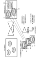
- Figure 6 is an image of the processing by the information processing device 103.
- Figure 7 is an image of the processing by the explanation unit 113 of the second embodiment.
- the information processing device 103 includes a detection unit 111, a determination unit 112, an explanation unit 113, and an output unit 114.
- the detection unit 111, the determination unit 112, the explanation unit 113, and the output unit 114 are realized by, for example, executing a program.
- the detection unit 111 shown in FIG. 5 has an object detection model (first trained model), and receives image data captured by the imaging device 2.
- the object detection model is a detector trained to detect targets (here, objects) by receiving image data as input. There are no particular limitations on the type or configuration of the object detection model, or on the training method for the object detection model.
- the object detection model detects an area of an object to be detected in an image (target area), and outputs information on the target area (which may be information on a frame surrounding the detected area, etc.) as the detection result.
- the detection unit 111 outputs image data used in the detection and the detection result to the output unit 114.
- the detection unit 111 also outputs image data obtained by cutting out the target region to the discrimination unit 112.
- 6 illustrates an example in which the object detection model detects a target region D1 corresponding to a first object, a target region D2 corresponding to a second object, and a target region D3 corresponding to a third object.
- the detection unit 111 outputs image data E1 obtained by cutting out the target region D1, image data E2 obtained by cutting out the target region D2, and image data E3 obtained by cutting out the target region D3 to the discrimination unit 112.
- the discrimination unit 112 shown in FIG. 5 has a model for the target region (second trained model), and image data of the target region cut out is input to this model.
- a classification model will be assumed as the second trained model.
- the classification model is a detector that is trained to classify targets (here, objects) that appear in an image by inputting image data.
- the classification model may be configured, for example, as a Convolutional Neural Network (CNN), and may use the techniques of "EfficientNet” or "Residual Network (ResNet)". There are no particular limitations on the method of training the classification model.
- CNN Convolutional Neural Network
- the classification model identifies the target (here, object) that appears in the image from which the target area has been cut out, and outputs the object discrimination result.
- the object discrimination result may be, for example, the object name or type of object.
- image data E1 from which the target area D1 has been cut out is input to the classification model, and the classification model outputs the type of the first object.
- image data E2 from which the target area D2 has been cut out is input to the classification model, and the classification model outputs the type of the second object.
- image data E3 from which the target area D3 has been cut out is input to the classification model, and the classification model outputs the type of the third object.
- Anomalies to be detected include, for example, unevenness or scratches.
- the target region becomes an anomaly candidate, and the anomaly candidate is input to the classification model.
- the classification model then outputs the type of unevenness or type of scratch.
- the discrimination unit 112 outputs the feature amount of the classification model after discriminating the object to the explanation unit 113.
- the discrimination unit 112 acquires the feature amount of the classification model for each object, and outputs the feature amount of the classification model to the explanation unit 113 in association with the classified object.
- the discrimination unit 112 acquires the feature amount of the classification model that classified the image data E1 that has been cut out from the object region D1, and outputs the feature amount to the explanation unit 113 in association with the first object.
- the discrimination unit 112 also acquires the feature amount of the classification model that has classified the image data E2 that has been cut out from the object region D2, and outputs the feature amount to the explanation unit 113 in association with the second object.
- the discrimination unit 112 also acquires the feature amount of the classification model that has classified the image data E3 that has been cut out from the object region D3, and outputs the feature amount to the explanation unit 113 in association with the third object.
- the explanation unit 113 applies the XAI method to the features of the model for the target region (here, a classification model) and determines the reason why the detection unit 111 detected the target region for each target region (for each detection target). The explanation unit 113 then associates the reason for detection with the target region and outputs it to the output unit 114 as explanation information.
- the XAI method used by the explanation unit 113 is not particularly limited, and may be, for example, a method such as CAM (Class Activation Map), SHAP (Shapley Additive exPlanations), or similar image search.
- the explanation unit 113 applies the XAI method to the feature amount of the classification model that classified the image data E1 that has been cut out from the target region D1, and finds the reason for the detection of the first object (target region D1).
- the explanation unit 113 also applies the XAI method to the feature amount of the classification model that classified the image data E2 that has been cut out from the target region D2, and finds the reason for the detection of the second object (target region D2).
- the explanation unit 113 also applies the XAI method to the feature amount of the classification model that classified the image data E3 that has been cut out from the target region D3, and finds the reason for the detection of the third object (target region D3).
- the explanation unit 113 then outputs the reason for the detection of the first object (target region D1), the reason for the detection of the second object (target region D2), and the reason for the detection of the third object (target region D3) to the output unit 114 as explanation information.
- the explanation unit 113 uses a similar image search technique as XAI.
- the explanation unit 113 searches the learning image data for images that show an object similar to the detected target. For example, the explanation unit 113 searches image data by comparing features, and acquires images that show object A and object B as images that are similar to the detected first object. The explanation unit 113 also acquires images that show object D and object E as images that are similar to the detected second object. Although not shown, the explanation unit 113 also acquires images that are similar to the detected third object using a similar method. The explanation unit 113 outputs the searched similar images and information based on the similar images (for example, an explanation obtained from the similar images) to the output unit 114.
- the output unit 114 shown in FIG. 5 creates information (display screen information) to be displayed on the display device 4 (see FIG. 1). As shown in FIG. 5, the output unit 114 receives image data and detection results from the detection unit 111, and also receives explanatory information from the explanation unit 113. The output unit 114 reflects the object detection results in the image data, and creates display screen information that associates the reason for detecting the detection target with the detection result. For example, the output unit 114 creates display screen information that includes image data reflecting the detection results and an image that is similar to the detected target. The output unit 114 outputs the created display screen information to the display device 4.
- the information processing device 103 according to the second embodiment of the present invention configured as above provides the following advantageous effects.
- the information processing device 103 according to this embodiment has the same effect as the information processing device 3 according to the first embodiment.
- the information processing device 103 according to this embodiment includes a detection unit 111, a discrimination unit 112, and an explanation unit 113.
- the discrimination unit 112 acquires the feature amount of a model for a target area (here, a classification model).
- the explanation unit 113 applies the XAI method to the feature amount of the model, and obtains the reason why the detection unit 111 detected the target area for each target area (for each detection target). Therefore, even if there are multiple detection points in an image, the detection result can be correctly explained.
- the XAI technique is applied to a masked feature map obtained by masking a feature map of an object detection model (first trained model).
- the difference from the first embodiment is the configuration of an information processing device 3, and the following description will focus on the difference.
- Fig. 8 shows an example of the configuration of the information processing device 203.
- Fig. 9 shows an image of the processing by the information processing device 203.
- the information processing device 203 includes a detection unit 211, a mask processing unit 212, an explanation unit 213, and an output unit 214.
- the detection unit 211, the mask processing unit 212, the explanation unit 213, and the output unit 214 are realized by, for example, executing a program.
- the detection unit 211 shown in FIG. 8 has an object detection model (first trained model), and receives image data captured by the imaging device 2.
- the object detection model is a detector trained to detect targets (here, objects) by receiving image data as input. There are no particular limitations on the type or configuration of the object detection model, or on the training method for the object detection model.
- the object detection model detects an area of an object to be detected in an image (target area), and outputs information on the target area (which may be information on a frame surrounding the detected area, etc.) as the detection result.
- the detection unit 211 outputs image data used in the detection and the detection result to the output unit 214. In addition, the detection unit 211 outputs a feature map of the object detection model and the detection result to the mask processing unit 212. 9 illustrates an example in which the object detection model detects a target region D1 corresponding to a first object, a target region D2 corresponding to a second object, and a target region D3 corresponding to a third object. In this case, the detection unit 211 outputs information on the target region D1, the target region D2, and the target region D3 to the mask processing unit 212 as detection results.
- the feature map of the object detection model and the detection results are input to the mask processing unit 212 shown in FIG. 8.
- the mask processing unit 212 masks the feature map using the detection results, and outputs the masked feature map to the explanation unit 213.
- the mask processing unit 212 creates a masked feature map for each detection target, in which the area other than the area corresponding to the target area is the masked area, and outputs the masked feature map to the explanation unit 213 in association with the detection target.
- the mask processing unit 212 masks the feature map using, for example, binarization processing or contour extraction processing. Note that masking may also be performed based on the gaze area of the feature map.
- the mask processing unit 212 creates a masked feature map G1 in which the area other than the area corresponding to the target area D1 is masked, and outputs the masked feature map G1 to the explanation unit 213 in association with the first object.
- the mask processing unit 212 also creates a masked feature map G2 in which the area other than the area corresponding to the target area D2 is masked, and outputs the masked feature map G2 to the explanation unit 213 in association with the second object.
- the mask processing unit 212 also creates a masked feature map G3 in which the area other than the area corresponding to the target area D3 is masked, and outputs the masked feature map G3 to the explanation unit 213 in association with the third object.
- the explanation unit 213 shown in FIG. 8 applies the XAI method to a masked feature map obtained by masking the feature map of the object detection model (first trained model), and determines the reason why the detection unit 211 detected the target area for each target area (for each detection target). The explanation unit 213 then associates the reason for detection with the target area and outputs it to the output unit 214 as explanation information.
- the XAI method used by the explanation unit 213 is not particularly limited, and may be, for example, a method using CAM (Class Activation Map), SHAP (Shapley Additive exPlanations), similar image search, or the like.
- the explanation unit 213 uses the similar image search method as XAI, for example, an image similar to the detected target is searched for from the learning image data by processing similar to that of the second embodiment (see FIG. 7).
- the explanation unit 213 applies the XAI method to the masked feature map G1 in which the area other than the area corresponding to the target area D1 is the masked area, and obtains the reason for the detection of the first object (target area D1).
- the explanation unit 213 also applies the XAI method to the masked feature map G2 in which the area other than the area corresponding to the target area D2 is the masked area, and obtains the reason for the detection of the second object (target area D2).
- the explanation unit 213 also applies the XAI method to the masked feature map G3 in which the area other than the area corresponding to the target area D3 is the masked area, and obtains the reason for the detection of the third object (target area D3).
- the explanation unit 213 then outputs the reasons for the detection of the first object (target area D1), the second object (target area D2), and the third object (target area D3) to the output unit 214 as explanation information.
- the processing of the output unit 214 is similar to that of the output unit 114 in the second embodiment (see FIG. 5).
- the information processing device 203 according to the third embodiment of the present invention configured as above provides the following advantageous effects.
- the information processing device 203 according to this embodiment has the same effect as the information processing device 3 according to the first embodiment.
- the information processing device 203 according to this embodiment includes a detection unit 211, a mask processing unit 212, and an explanation unit 213.
- the mask processing unit 212 creates a masked feature map by masking the feature map of the object detection model.
- the explanation unit 213 applies the XAI method to the masked feature map, and obtains the reason why the detection unit 211 detected the target area for each target area (for each detection target). Therefore, even if there are multiple detection points in the image, the detection result can be correctly explained.
Landscapes
- Engineering & Computer Science (AREA)
- Theoretical Computer Science (AREA)
- Physics & Mathematics (AREA)
- General Physics & Mathematics (AREA)
- Artificial Intelligence (AREA)
- Software Systems (AREA)
- Evolutionary Computation (AREA)
- Computing Systems (AREA)
- Mathematical Physics (AREA)
- General Health & Medical Sciences (AREA)
- Data Mining & Analysis (AREA)
- Computational Linguistics (AREA)
- Medical Informatics (AREA)
- Health & Medical Sciences (AREA)
- Computer Vision & Pattern Recognition (AREA)
- General Engineering & Computer Science (AREA)
- Biomedical Technology (AREA)
- Biophysics (AREA)
- Molecular Biology (AREA)
- Life Sciences & Earth Sciences (AREA)
- Databases & Information Systems (AREA)
- Multimedia (AREA)
- Image Analysis (AREA)
Priority Applications (1)
| Application Number | Priority Date | Filing Date | Title |
|---|---|---|---|
| JP2024565813A JPWO2024135423A1 (https=) | 2022-12-23 | 2023-12-08 |
Applications Claiming Priority (2)
| Application Number | Priority Date | Filing Date | Title |
|---|---|---|---|
| JP2022-207135 | 2022-12-23 | ||
| JP2022207135 | 2022-12-23 |
Publications (1)
| Publication Number | Publication Date |
|---|---|
| WO2024135423A1 true WO2024135423A1 (ja) | 2024-06-27 |
Family
ID=91588638
Family Applications (1)
| Application Number | Title | Priority Date | Filing Date |
|---|---|---|---|
| PCT/JP2023/044118 Ceased WO2024135423A1 (ja) | 2022-12-23 | 2023-12-08 | 情報処理装置、情報処理方法、プログラムおよび情報処理システム |
Country Status (2)
| Country | Link |
|---|---|
| JP (1) | JPWO2024135423A1 (https=) |
| WO (1) | WO2024135423A1 (https=) |
Citations (6)
| Publication number | Priority date | Publication date | Assignee | Title |
|---|---|---|---|---|
| JP2018151843A (ja) * | 2017-03-13 | 2018-09-27 | ファナック株式会社 | 入力画像から検出した対象物の像の尤度を計算する画像処理装置および画像処理方法 |
| JP2019082883A (ja) * | 2017-10-31 | 2019-05-30 | 株式会社デンソー | 推論装置、推論方法及びプログラム |
| JP2019164611A (ja) * | 2018-03-20 | 2019-09-26 | アイシン・エィ・ダブリュ株式会社 | 走行支援装置及びコンピュータプログラム |
| JP2020166378A (ja) * | 2019-03-28 | 2020-10-08 | 京セラ株式会社 | 疾患推定システム |
| WO2022186182A1 (ja) * | 2021-03-04 | 2022-09-09 | 日本電気株式会社 | 予測装置、予測方法、及び、記録媒体 |
| JP2022146822A (ja) * | 2021-03-22 | 2022-10-05 | ソニーグループ株式会社 | 画像診断システム及び画像診断方法 |
-
2023
- 2023-12-08 JP JP2024565813A patent/JPWO2024135423A1/ja active Pending
- 2023-12-08 WO PCT/JP2023/044118 patent/WO2024135423A1/ja not_active Ceased
Patent Citations (6)
| Publication number | Priority date | Publication date | Assignee | Title |
|---|---|---|---|---|
| JP2018151843A (ja) * | 2017-03-13 | 2018-09-27 | ファナック株式会社 | 入力画像から検出した対象物の像の尤度を計算する画像処理装置および画像処理方法 |
| JP2019082883A (ja) * | 2017-10-31 | 2019-05-30 | 株式会社デンソー | 推論装置、推論方法及びプログラム |
| JP2019164611A (ja) * | 2018-03-20 | 2019-09-26 | アイシン・エィ・ダブリュ株式会社 | 走行支援装置及びコンピュータプログラム |
| JP2020166378A (ja) * | 2019-03-28 | 2020-10-08 | 京セラ株式会社 | 疾患推定システム |
| WO2022186182A1 (ja) * | 2021-03-04 | 2022-09-09 | 日本電気株式会社 | 予測装置、予測方法、及び、記録媒体 |
| JP2022146822A (ja) * | 2021-03-22 | 2022-10-05 | ソニーグループ株式会社 | 画像診断システム及び画像診断方法 |
Also Published As
| Publication number | Publication date |
|---|---|
| JPWO2024135423A1 (https=) | 2024-06-27 |
Similar Documents
| Publication | Publication Date | Title |
|---|---|---|
| Bergmann et al. | The MVTec anomaly detection dataset: a comprehensive real-world dataset for unsupervised anomaly detection | |
| JP7649350B2 (ja) | ビジョンシステムで画像内のパターンを検出及び分類するためのシステム及び方法 | |
| Tariq et al. | Quality assessment methods to evaluate the performance of edge detection algorithms for digital image: A systematic literature review | |
| JP2019101919A (ja) | 情報処理装置、情報処理方法、コンピュータプログラムおよび記憶媒体 | |
| US20230053085A1 (en) | Part inspection system having generative training model | |
| CN111967490A (zh) | 用于地图检测的模型训练方法和地图检测方法 | |
| CN116735723B (zh) | 一种钢轨伤损超声定位识别系统 | |
| KR20210026176A (ko) | 딥 러닝을 위한 라벨링 이미지 생성 방법 | |
| EP3404513A1 (en) | Information processing apparatus, method, and program | |
| Lee | 16‐4: Invited Paper: Region‐Based Machine Learning for OLED Mura Defects Detection | |
| JP7713224B2 (ja) | モデル評価方法およびモデル評価システム | |
| Dai et al. | Detection and segmentation of image anomalies based on unsupervised defect reparation | |
| Jovančević et al. | Automated visual inspection of an airplane exterior | |
| CN120951053B (zh) | 一种异物分层检测的方法、系统及电子设备 | |
| Wang et al. | Research on Deep Learning-based Object Detection Algorithm in Construction Sites | |
| JP2024160599A (ja) | コンピュータプログラム、タスク生成装置及びタスク生成方法 | |
| WO2024135423A1 (ja) | 情報処理装置、情報処理方法、プログラムおよび情報処理システム | |
| Servi et al. | Integration of artificial intelligence and augmented reality for assisted detection of textile defects | |
| Zhang et al. | Exploratory image data analysis for quality improvement hypothesis generation | |
| CN115428012A (zh) | 图像检查装置、图像检查方法以及学习完毕模型生成装置 | |
| Wang et al. | Post-processing for retinal vessel detection | |
| Plassmann et al. | Automated Annotation of Shearographic Measurements Enabling Weakly Supervised Defect Detection | |
| JP7391285B2 (ja) | プログラム、情報処理装置、情報処理方法及びモデル生成方法 | |
| Wang et al. | Face detection based on color template and least square matching method | |
| JP7507125B2 (ja) | 検査装置用情報処理装置、検査装置用情報処理方法、及び検査装置システム |
Legal Events
| Date | Code | Title | Description |
|---|---|---|---|
| 121 | Ep: the epo has been informed by wipo that ep was designated in this application |
Ref document number: 23906789 Country of ref document: EP Kind code of ref document: A1 |
|
| WWE | Wipo information: entry into national phase |
Ref document number: 2024565813 Country of ref document: JP |
|
| NENP | Non-entry into the national phase |
Ref country code: DE |
|
| 122 | Ep: pct application non-entry in european phase |
Ref document number: 23906789 Country of ref document: EP Kind code of ref document: A1 |