WO2024135191A1 - ヘッダ管、熱交換器、ヘッダ管の製造方法及び熱交換器の製造方法 - Google Patents
ヘッダ管、熱交換器、ヘッダ管の製造方法及び熱交換器の製造方法 Download PDFInfo
- Publication number
- WO2024135191A1 WO2024135191A1 PCT/JP2023/041496 JP2023041496W WO2024135191A1 WO 2024135191 A1 WO2024135191 A1 WO 2024135191A1 JP 2023041496 W JP2023041496 W JP 2023041496W WO 2024135191 A1 WO2024135191 A1 WO 2024135191A1
- Authority
- WO
- WIPO (PCT)
- Prior art keywords
- header
- tube
- pipe
- outer tube
- heat transfer
- Prior art date
- Legal status (The legal status is an assumption and is not a legal conclusion. Google has not performed a legal analysis and makes no representation as to the accuracy of the status listed.)
- Ceased
Links
Images









Classifications
-
- F—MECHANICAL ENGINEERING; LIGHTING; HEATING; WEAPONS; BLASTING
- F28—HEAT EXCHANGE IN GENERAL
- F28D—HEAT-EXCHANGE APPARATUS, NOT PROVIDED FOR IN ANOTHER SUBCLASS, IN WHICH THE HEAT-EXCHANGE MEDIA DO NOT COME INTO DIRECT CONTACT
- F28D1/00—Heat-exchange apparatus having stationary conduit assemblies for one heat-exchange medium only, the media being in contact with different sides of the conduit wall, in which the other heat-exchange medium is a large body of fluid, e.g. domestic or motor car radiators
- F28D1/02—Heat-exchange apparatus having stationary conduit assemblies for one heat-exchange medium only, the media being in contact with different sides of the conduit wall, in which the other heat-exchange medium is a large body of fluid, e.g. domestic or motor car radiators with heat-exchange conduits immersed in the body of fluid
- F28D1/04—Heat-exchange apparatus having stationary conduit assemblies for one heat-exchange medium only, the media being in contact with different sides of the conduit wall, in which the other heat-exchange medium is a large body of fluid, e.g. domestic or motor car radiators with heat-exchange conduits immersed in the body of fluid with tubular conduits
- F28D1/053—Heat-exchange apparatus having stationary conduit assemblies for one heat-exchange medium only, the media being in contact with different sides of the conduit wall, in which the other heat-exchange medium is a large body of fluid, e.g. domestic or motor car radiators with heat-exchange conduits immersed in the body of fluid with tubular conduits the conduits being straight
- F28D1/05316—Assemblies of conduits connected to common headers, e.g. core type radiators
-
- F—MECHANICAL ENGINEERING; LIGHTING; HEATING; WEAPONS; BLASTING
- F28—HEAT EXCHANGE IN GENERAL
- F28F—DETAILS OF HEAT-EXCHANGE AND HEAT-TRANSFER APPARATUS, OF GENERAL APPLICATION
- F28F9/00—Casings; Header boxes; Auxiliary supports for elements; Auxiliary members within casings
- F28F9/02—Header boxes; End plates
- F28F9/026—Header boxes; End plates with static flow control means, e.g. with means for uniformly distributing heat exchange media into conduits
- F28F9/027—Header boxes; End plates with static flow control means, e.g. with means for uniformly distributing heat exchange media into conduits in the form of distribution pipes
- F28F9/0273—Header boxes; End plates with static flow control means, e.g. with means for uniformly distributing heat exchange media into conduits in the form of distribution pipes with multiple holes
Definitions
- the present disclosure relates to a header tube, a heat exchanger, a method for manufacturing a header tube, and a method for manufacturing a heat exchanger.
- a heat exchanger is a component of a refrigeration circuit, and generally comprises two header pipes and multiple heat transfer pipes connecting the two header pipes.
- One of the two header pipes is connected to a pipeline on the upstream side of the refrigeration circuit, and refrigerant flows into it from the upstream side of the refrigeration circuit.
- the refrigerant that flows into one header pipe is distributed to multiple heat transfer pipes and flows into the other header pipe through the multiple heat transfer pipes.
- the refrigerant that flows into the other header pipe is collected there.
- the other header pipe is connected to a pipeline on the downstream side of the refrigeration circuit, and the collected refrigerant flows out to the downstream side of the refrigeration circuit.
- heat exchangers are equipped with multiple heat transfer fins that cross the multiple heat transfer tubes and are in thermal contact with them. By providing heat transfer fins, the heat transfer area of the heat exchanger with respect to the surrounding air is increased, improving the efficiency of heat exchange.
- Patent Document 1 discloses a flat-tube evaporator, which is a type of heat exchanger.
- the inlet manifold of this flat-tube evaporator corresponds to a header pipe arranged upstream of the heat exchanger, and the flat tubes correspond to heat transfer tubes.
- a distribution pipe is inserted into the inlet manifold, and the distribution pipe has multiple orifices. Refrigerant flowing in from the upstream side of the refrigeration circuit is guided to the distribution pipe, passes through the orifices, and flows out of the distribution pipe to the flat tube. The refrigerant flows through the flat tube to the outlet manifold.
- the header tube of the flat tube evaporator described in Patent Document 1 includes an outer tube connected to multiple heat transfer tubes and an inner tube inserted into the outer tube, with the inner tube having multiple small holes on its side.
- the refrigerant that flows into the outer tube is guided to the inner tube, passes through the small holes, and flows out of the inner tube and is guided to the flat tubes, so that the refrigerant can be evenly distributed to the multiple heat transfer tubes.
- Patent Document 1 as shown in Figure 4, the inner tube is cantilevered at one end of the outer tube. This causes a problem in that the relative position of the inner tube to the outer tube is not stable. In particular, during the manufacturing process of the header tube, the inner tube may bend due to the heat of brazing, which may result in the inner tube becoming misaligned with respect to the outer tube. If the inner tube becomes misaligned with respect to the outer tube, the flow of the refrigerant in the header tube changes, and there is a risk that the designed performance will not be achieved.
- the present disclosure has been made in consideration of the above problems, and aims to provide a header tube in which the inner tube is stably held by the outer tube, and a heat exchanger including the header tube. It also aims to provide a method for manufacturing such a header tube and heat exchanger.
- the header tube disclosed herein comprises an outer tube to which multiple heat transfer tubes are connected, and an inner tube that is inserted into the outer tube and has multiple small holes, and comprises multiple support members that are spaced apart in the longitudinal direction of the outer tube and support the inner tube. In the space between the inner tube and the outer tube, a gap is formed through which the refrigerant flows in the longitudinal direction of the header tube over the support members.
- a plurality of support members are provided, and the inner tube is supported on the outer tube via the plurality of support members.
- the inner tube is supported at multiple points. Therefore, the inner tube is stably held on the outer tube, and the occurrence of misalignment of the inner tube relative to the outer tube is suppressed.
- FIG. 1 is a front view showing a configuration of a heat exchanger including a header tube according to an embodiment of the present disclosure
- FIG. 2 is a cross-sectional view showing an internal configuration of a header pipe provided in the heat exchanger shown in FIG.
- FIG. 3 is a cross-sectional view of the header pipe taken along line IIIA - IIIA in FIG. 3 is a cross-sectional view of the header pipe shown in FIG. 2 taken along line IIIB - IIIB.
- 4 is a cross-sectional view of the header shown in FIG. 2 taken along line IV-IV.
- FIG. 1 is an explanatory diagram showing a manufacturing process of a header pipe according to an embodiment of the present disclosure in chronological order.
- FIG. 1 is an explanatory diagram showing a manufacturing process of a header pipe according to an embodiment of the present disclosure in chronological order.
- FIG. 1 is an explanatory diagram showing a manufacturing process of a header pipe according to an embodiment of the present disclosure in chronological order.
- FIG. 1 is an explanatory diagram showing a manufacturing process of a header pipe according to an embodiment of the present disclosure in chronological order.
- FIG. 1 is an explanatory diagram showing a manufacturing process of a header pipe according to an embodiment of the present disclosure in chronological order.
- FIG. 1 is an explanatory diagram showing a manufacturing process of a header pipe according to an embodiment of the present disclosure in chronological order.
- FIG. 1 is an explanatory diagram showing a manufacturing process of a header pipe according to an embodiment of the present disclosure in chronological order.
- FIG. 1 is an explanatory diagram showing a manufacturing process of a header pipe according to an embodiment of the present disclosure in chronological order.
- FIG. 1 is an explanatory diagram showing a process of assembling a lid portion to a main body portion of an outer pipe of a header pipe in a time sequence according to an embodiment of the present disclosure.
- FIG. 1 is an explanatory diagram showing a process of assembling a lid portion to a main body portion of an outer pipe of a header pipe in a time sequence according to an embodiment of the present disclosure.
- FIG. 1 is an explanatory diagram showing a process of assembling a lid portion to a main body portion of an outer pipe of a header pipe in a time sequence according to an embodiment of the present disclosure.
- FIG. 1 is a plan view showing a detailed shape of a fixing member according to an embodiment of the present disclosure; FIG.
- FIG. 11 is a plan view showing a detailed shape of a fixing member according to a modified example;
- FIG. 11 is a cross-sectional view showing an internal configuration of a header pipe according to a first modified example.
- FIG. 11 is a cross-sectional view showing an internal configuration of a header pipe according to a second modified example.
- FIG. 13 is a side view showing the outer shape of an outer pipe included in a header pipe according to a third modified example.
- 10B is a cross-sectional view of the outer tube shown in FIG. 10A taken along line XX.
- FIG. 13 is a plan view showing an outer shape of a support member provided in a header pipe according to a third modified example. 10B shows a state in which the support member shown in FIG.
- FIG. 10C is attached to the outer tube shown in FIG. 10B.
- FIG. 13 is a side view showing the outer shape of an outer pipe included in a header pipe according to a fourth modified example.
- FIG. 13 is a plan view showing an outer shape of a support member provided in a header pipe according to a fourth modified example.
- 11B shows a state in which the support member shown in FIG. 11C is attached to the outer tube shown in FIG. 11B.
- FIG. 11D is a cross-sectional view of the main body and the support member taken along line XI d -XI d of FIG. 11D, showing the shape of the fillet formed around the fitting groove and the protruding piece.
- FIG. 11D is a cross-sectional view of the main body and the support member taken along line XI d -XI d of FIG. 11D, showing the shape of the fillet formed around the fitting groove and
- FIG. 12B is a cross-sectional view showing the shape of a fillet formed around a fitting groove and a protruding piece according to another embodiment of the present invention
- FIG. 3B is a cross-sectional view showing a modified example of the outer tube according to the embodiment of the present disclosure, following FIG.
- FIG. 3B is a cross-sectional view showing another modified example of the outer tube according to the embodiment of the present disclosure, in accordance with FIG.
- FIG. 1 is a front view showing a configuration of a heat exchanger 1 including a header tube 2 according to an embodiment of the present disclosure.
- the heat exchanger 1 includes two header tubes 2 arranged parallel to each other, a plurality of heat transfer tubes 3 arranged between the two header tubes 2 and allowing a refrigerant to flow between the two header tubes 2, and a plurality of heat transfer fins 4 arranged to intersect with the plurality of heat transfer tubes 3 and in thermal contact with the plurality of heat transfer tubes 3.
- the heat exchanger 1 is a component of a refrigeration circuit (not shown), and one of the two header pipes 2 is connected to a pipeline on the upstream side of the refrigeration circuit, from which the refrigerant flows in.
- the refrigerant that flows into one header pipe 2 is distributed to multiple heat transfer pipes 3, passes through the heat transfer pipes 3, and flows into the other header pipe 2.
- the other header pipe 2 is connected to a pipeline on the downstream side of the refrigeration circuit, and the refrigerant that flows into the other header pipe 2 flows out into the pipeline on the downstream side.
- the heat exchanger 1 While the refrigerant passes through the heat transfer tubes 3, heat exchange takes place between the refrigerant and the air surrounding the heat exchanger 1.
- the heat exchanger 1 is equipped with multiple heat transfer fins 4, the heat transfer area of the heat exchanger 1 with respect to the air surrounding the heat exchanger 1 is large. As a result, the heat exchanger 1 has high heat exchange efficiency.
- Fig. 2 is a cross-sectional view showing the internal structure of the header pipe 2 included in the heat exchanger 1.
- the header pipe 2 includes an outer pipe 5 that forms the outer shell of the header pipe 2, and an inner pipe 6 that is inserted into the outer pipe 5.
- the inner pipe 6 is penetrated by a plurality of small holes 6a that are equally spaced apart on its side surface and arranged in two rows in the longitudinal direction of the inner pipe 6.
- the header pipe 2 is provided with two fixing members 7 that are spaced apart in the longitudinal direction of the outer pipe 5 and fix the portions of the inner pipe 6 near both ends to the outer pipe 5.
- the fixing members 7 seal the gap between the inner pipe 6 and the outer pipe 5. Therefore, the fixing members 7 airtightly divide the space between the inner pipe 6 and the outer pipe 5 in the longitudinal direction of the outer pipe 5.
- the multiple small holes 6a in the inner pipe 6 are formed only between the two fixing members 7. The right end of the inner pipe 6 in the drawing is also closed.
- multiple support members 8 are arranged in the space between the inner tube 6 and the outer tube 5, which is between the two fixing members 7.
- the support members 8 are fixed to the outer tube 5 and support the inner tube 6.
- cover members 9 are attached to both ends of the outer pipe 5 in the longitudinal direction.
- the cover members 9 are fitted into both ends of the outer pipe 5, airtightly closing both ends of the outer pipe 5.
- the header pipe 2 is also provided with an outlet pipe 10. The refrigerant that flows in and out of the header pipe 2 flows in and out of the outer pipe 5 through the outlet pipe 10.
- the inner pipe 6 is supported by the outer pipe 5 via a plurality of fixing members 7 and support members 8, so the inner pipe 6 is stably held by the outer pipe 5. This prevents the inner pipe 6 from becoming misaligned during the manufacturing process of the header pipe 2, which will be described later. This makes it easier to manufacture the header pipe 2. In addition, the performance of the header pipe 2 is stable.
- the refrigerant flowing in from the upstream pipeline passes through the outlet pipe 10 and flows into the space between the cover member 9 and the fixed member 7 on the left side in FIG. 2.
- the refrigerant that flows into the space between the cover member 9 and the fixed member 7 flows from there into the inner pipe 6.
- the refrigerant that flows into the inner pipe 6 passes through the multiple small holes 6a in the inner pipe 6 and is distributed to the multiple heat transfer pipes 3.
- the refrigerant then flows through the multiple heat transfer pipes 3 to the other header pipe 2.
- the refrigerant that has passed through the heat transfer tubes 3 and flowed into the other header tube 2 passes through the small holes 6a in the inner tube 6 and flows into the interior of the inner tube 6.
- the refrigerant that has flowed into the interior of the inner tube 6 flows into the space between the cover member 9 and the fixed member 7 on the left side of the other header tube 2 in FIG. 2, and from there flows through the extraction pipe 10 into the piping downstream of the header tube 2 in the refrigeration circuit (not shown).
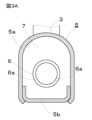
- FIG. 3A is a cross-sectional view of the header pipe 2 cut along a plane indicated by line IIIA - IIIA in Fig. 2.
- Fig. 3B is a cross-sectional view of the header pipe 2 cut along a plane indicated by line IIIB - IIIB in Fig. 2.
- the fixing member 7 closes all the gaps between the inner pipe 6 and the outer pipe 5.
- the inner pipe 6 penetrates the fixing member 7.
- the fixing member 7 is fixed to the inner pipe 6 and the outer pipe 5 by brazing.
- the minute gaps between the fixing member 7 and the inner pipe 6 and between the fixing member 7 and the outer pipe 5 are filled with brazing material. Therefore, the space between the inner pipe 6 and the outer pipe 5 is airtightly partitioned by the fixing member 7 in the longitudinal direction of the outer pipe 5.
- the outer tube 5 is composed of a main body 5a having a U-shaped cross section and a bottom plate 5b that closes the open end of the U-shaped cross section.
- FIG. 4 is a cross-sectional view of the header pipe 2 taken along the plane indicated by IV-IV in Fig. 2. As shown in Fig. 4, the support member 8 is disposed between the inner pipe 6 and the outer pipe 5 to support the inner pipe 6. The inner pipe 6 also passes through the support member 8.
- a first gap 8a is formed between the support member 8 and the outer tube 5.
- the support member 8 and the heat transfer tubes 3 do not interfere with each other. Also, the flow of refrigerant entering and exiting the heat transfer tube 3 is less likely to be affected by the support member 8.
- a second gap 8b is formed between the inner tube 6 and the support member 8.
- the second gap 8b is arranged symmetrically in two locations.
- the second gap 8b is arranged at a position where the small hole 6a faces the second gap 8b. Therefore, even if the support member 8 is arranged at a position where it overlaps with the small hole 6a, the support member 8 does not block the small hole 6a. Therefore, the attachment position of the support member 8 can be selected without considering the arrangement of the small hole 6a.
- a first gap 8a is formed between the support member 8 and the outer pipe 5, and a second gap 8b is formed between the support member 8 and the inner pipe 6, which enables the refrigerant to flow in the longitudinal direction of the header pipe 2 in the space between the inner pipe 6 and the outer pipe 5, beyond the support member 8.
- FIG. 4 if the inner tube 6 is likened to a clock face, two rows of small holes 6a are formed at positions corresponding to approximately 4 o'clock and 8 o'clock, but this position is an example.
- the positions of the small holes 6a can be selected arbitrarily in the design.
- the number of small holes 6a appearing in FIG. 4 can also be selected arbitrarily in the design. In other words, in FIG. 4, there may be three or more rows of small holes 6a, or just one.
- the position and number of the second gaps 8b can be selected appropriately according to the positions and number of the small holes 6a.
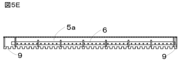
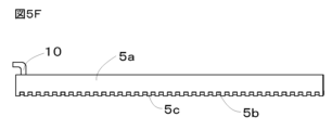
- FIGS. 5A to 5F are explanatory diagrams showing, in chronological order, the manufacturing process of the header pipe 2. The manufacturing method of the header pipe 2 will be described below with reference to FIGS.
- each of the components that make up the header pipe 2 is manufactured separately. That is, the main body 5a and bottom plate 5b that make up the outer pipe 5 are manufactured by bending material cut out from a metal plate.
- the inner pipe 6 is manufactured by cutting a metal pipe material and then drilling small holes 6a.
- the fixing member 7, support member 8, and cover member 9 are cut out from a metal plate.
- the extraction pipe 10 is manufactured by cutting a metal pipe material and then bending it. Additionally, brazing material is applied to the necessary areas of each of the above components.
- the inner tube 6 is inserted into one fixing member 7 as shown in Fig. 5A.
- the inner tube 6 is positioned relative to the fixing member 7 so that the small hole 6a faces a predetermined direction, i.e., the direction shown in Fig. 3A.
- a tube expansion tool 11 is pushed into the inner tube 6 to expand the portion of the inner tube 6 that intersects with the fixing member 7.
- the inner tube 6 is fixed to the fixing member 7 in the state shown in Fig. 5B.
- the inner tube 6 is fixed to the fixing member 7 while maintaining the state in which the small hole 6a faces the predetermined direction, i.e., the direction shown in Fig. 3A.
- the inner pipe 6 that has been through the inner pipe assembling process i.e., the inner pipe 6 to which the fixing member 7 and the support member 8 are attached, is assembled to the main body 5a as shown in Fig. 5D.
- the inner pipe 6 since the inner pipe 6 is fixed to one of the fixing members 7 in the fixing member fixing process, the inner pipe 6 does not rotate around the central axis of the inner pipe 6 relative to the fixing member 7 before and after the inner pipe assembling process. Therefore, in the inner pipe assembling process, the inner pipe 6 is assembled to the main body 5a while maintaining the state shown in Fig. 5B.
- the main body 5a has a number of comb-tooth-shaped claws 5c. The function of the claws 5c will be described later.
- FIG. 6A to 6C are explanatory diagrams showing the process of assembling the bottom plate 5b to the main body 5a of the outer tube 5 in chronological order in the overall assembly process described above.
- FIG. 6A before the bottom plate 5b is assembled to the main body 5a, the claws 5c are in a straight state. Therefore, as shown in FIG. 6B, the bottom plate 5b can be inserted into the main body 5a. After the bottom plate 5b is inserted into the main body 5a, the claws 5c are bent as shown in FIG. 6C. When the claws 5c are bent, the bottom plate 5b is sandwiched between the fixing member 7 and the claws 5c. As a result, the bottom plate 5b is fixed to the main body 5a.
- the header tube 2 and the heat exchanger 1 equipped with the header tube 2 are manufactured.
- Fig. 7A is a plan view showing the detailed shape of the fixing member 7 included in the header pipe 2 shown in Fig. 2
- Fig. 7B is a plan view showing the detailed shape of the fixing member 7 according to a modified example.
- the fixing member 7 has an insertion hole 7a for inserting the inner tube 6.
- the insertion hole 7a has a planar shape that is similar to the cross-sectional shape of the inner tube 6. In other words, if the cross-section of the inner tube 6 is circular, the planar shape of the insertion hole 7a is circular. Also, as shown in FIG. 7A, the planar shape of the insertion hole 7a is slightly larger than the cross-sectional shape of the inner tube 6 before expansion, so that the inner tube 6 before expansion can be easily inserted into the insertion hole 7a. When the inner tube 6 is expanded, the inner tube 6 is in close contact with the fixing member 7.
- the planar shape of the insertion hole 7a may be dissimilar to the cross-sectional shape of the inner tube 6. If the planar shape of the insertion hole 7a is made dissimilar to the cross-sectional shape of the inner tube 6, then when the inner tube 6 is expanded, a portion of the fixing member 7 will bite deeply into the inner tube 6, and the inner tube 6 will be fixed to the fixing member 7 even more firmly. As a result, rotation of the inner tube 6 about its long axis relative to the fixing member 7 can be more reliably restricted.
- FIG. 8 is a cross-sectional view showing the configuration of a header pipe 2 according to a first modified example
- FIG. 9 is a cross-sectional view showing the configuration of a header pipe 2 according to a second modified example.
- the header pipe 2 is not limited to being provided with the fixing member 7 and the take-out pipe 10.
- the inner pipe 6 may be extended to the left side of the figure, penetrate the cover member 9, and the tip of the inner pipe 6 may protrude outside the header pipe 2.
- the inner pipe 6 may be bent into an L-shape at one end, penetrate the outer pipe 5, and one end of the inner pipe 6 may protrude outside the header pipe 2.
- the refrigerant entering and exiting the header pipe 2 can be directly entered and exited from the inner pipe 6, so the take-out pipe 10 is not necessary.
- the fixing member 7 is not necessary. Therefore, as shown in FIGS. 8 and 9, only a plurality of support members 8 are arranged at intervals in the longitudinal direction of the outer pipe 5 between the cover members 9 assigned to both ends of the outer pipe 5.
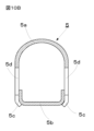
- Fig. 10A is a side view showing the outer shape of an outer pipe 5 included in a header pipe 2 (not shown in Fig. 10A) according to a third modified example
- Fig. 10B is a cross-sectional view showing the outer pipe 5 shown in Fig. 10A cut along the plane shown by line X-X in Fig. 10A
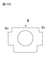
- Fig. 10C is a plan view showing the outer shape of a support member 8 included in a header pipe 2 according to a third modified example.
- Fig. 10D is a view showing a state in which the support member 8 shown in Fig. 10C is attached to the outer pipe 5 shown in Fig. 10B.
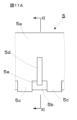
- a fitting groove 5d is formed on both sides of the main body 5a of the outer tube 5.
- the support member 8 has a protruding piece 8c.
- the fitting groove 5d is cut from the lower end of the main body 5, so that the protruding piece 8c can be inserted into the fitting groove 5d from below the main body 5a and fitted into the fitting groove 5d.
- the fitting groove 5d penetrates the main body 5a, and when the protruding piece 8c is fitted into the fitting groove 5d, the tip of the protruding piece 8c protrudes outside the main body 5a.
- the support member 8 is fixed to the main body 5a in the manner shown in Figure 10D.
- the header pipe 2 according to the third modified example has a fitting groove 5d in the main body 5a of the outer pipe 5, and the support member 8 has a protruding piece 8c that fits into the fitting groove 5d, so that the support member 8 can be easily positioned relative to the main body.
- This makes it easier to assemble the header pipe 2.
- the assembly accuracy of the header pipe 2 is improved.
- the tip of the protruding piece 8c protrudes outside the main body 5a, so that it is easy to confirm from outside the outer pipe 5 that the support member 8 has been assembled.
- the support member 8 is provided with the protruding piece 8c, but the member that has the protruding piece that fits into the fitting groove 5d is not limited to the support member 8.
- the fixing member 7 or the cover member 9 may also be provided with a protruding piece that fits into the fitting groove 5d.
- Fig. 11A is a side view showing the outer shape of an outer pipe 5 included in a header pipe 2 (not shown in Fig. 11A) according to a fourth modified example
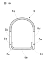
- Fig. 11B is a cross-sectional view showing the outer pipe 5 shown in Fig. 11A cut along the plane shown by line XI-XI in Fig. 11A
- Fig. 11C is a plan view showing the outer shape of a support member 8 included in a header pipe 2 according to a fourth modified example.
- Fig. 11D is a view showing a state in which the support member 8 shown in Fig. 11C is attached to the outer pipe 5 shown in Fig. 11B.
- the basic configuration and function of the header pipe 2 according to the fourth modified example is the same as that of the header pipe 2 according to the third modified example.
- the header pipe 2 according to the fourth modified example differs from the header pipe 2 according to the third modified example in that the header pipe 2 according to the fourth modified example has a second fitting groove 5e in the bottom plate 5b.
- the header pipe 2 according to the fourth modified example also differs from the header pipe 2 according to the third modified example in that the protruding piece 8c of the support member 8 fits into the second fitting groove 5e in addition to the fitting groove 5d.
- the bottom plate 5b can be positioned relative to the main body 5a by fitting the protruding piece 8c into the second fitting groove 5e. Therefore, the bottom plate 5b can be positioned relative to the main body 5a easily and accurately. As a result, the assembly of the header pipe 2 becomes easier. Also, the assembly accuracy of the header pipe 2 is further improved.
- the support member 8 is provided with the protruding piece 8c that fits into the fitting groove 5d and the second fitting groove 5e
- the member that has the protruding piece that fits into the fitting groove 5d and the second fitting groove 5e is not limited to the support member 8.
- the fixing member 7 or the cover member 9 may be provided with a protruding piece that fits into the fitting groove 5d and the second fitting groove 5e.
- the main body 5a and the bottom plate 5b are also manufactured by bending a material cut out from a metal plate. If the fitting groove 5d and the second fitting groove 5e are formed in the material and then bending is performed, the position of the fitting groove 5d or the second fitting groove 5e on the right side of the outer tube 5 and the position of the fitting groove 5d or the second fitting groove 5e on the left side of the outer tube 5 may not be aligned in the shape shown in FIG. 10B or FIG. 11B if the fitting groove 5d formed on the right side of the main body 5a in FIG.
- a gap may be generated between the fitting groove 5d formed on the left side of the main body 5a and the protruding piece 8c.
- a gap may be formed between the second fitting groove 5e formed on the right side of the bottom plate 5b and the protruding piece 8c. Therefore, it is preferable to form the fitting groove 5d and the second fitting groove 5e after bending the material. By forming the fitting groove 5d and the second fitting groove 5e after bending the material, it is possible to prevent the fitting groove 5d or the second fitting groove 5e from being misaligned on the left and right.
- Fig. 12A is a cross-sectional view showing the main body 5a and the support member 8 shown in Fig. 11D cut along the plane shown by line XI d -XI d in Fig. 11D, and shows the shape of the fillet formed around the fitting groove 5d and the protruding piece 8c.
- Fig. 12B is a cross-sectional view showing the shape of the fillet formed around the fitting groove 5d and the protruding piece 8c according to another example, following Fig. 12A.
- the tip of the protruding piece 8c of the support member 8 protrudes outside the outer tube 5. Therefore, when the support member 8 is brazed to the outer tube 5, as shown in FIG. 12A, a fillet 12 is formed on the inside and outside of the outer tube 5. As a result, the strength of the brazed portion is improved. In addition, it becomes easier to ensure airtightness and watertightness of the brazed portion.
- the shape and dimensions of the protruding piece 8c may also be selected so that the tip of the protruding piece 8c does not reach the outer surface of the outer tube 5.
- the tip of the protruding piece 8c may remain inside the fitting groove 5d.
- a fillet 12 is formed inside the outer tube 5 and inside the fitting groove 5d.
- the strength of the brazed portion is improved. It also becomes easier to ensure airtightness and watertightness of the brazed portion.
- FIG. 13A is a cross-sectional view showing a modified example of the outer tube 5 following FIG. 3A
- FIG. 13B is a cross-sectional view showing another modified example of the outer tube 5 following FIG. 3A.
- the cross section of the main body 5a of the outer tube 5 has a U-shaped cross section
- the cross section of the main body 5a may be groove-shaped, and is not limited to that shown in Figures 3A and 3B.
- the cross section of the main body 5a may be, for example, as shown in Figure 13A or Figure 13B. That is, the cross section of the main body 5a may have a linear contour and include two joints 5f, with the interior angles of each joint 5f forming a right angle, as shown in Figure 13A.
- the cross section of the main body 5a may have four joints 5f, with the interior angles of each joint 5f forming an obtuse angle, as shown in Figure 13B.
- a "groove shape” refers to a cross-sectional shape that is enclosed on three sides and has one open end. If another member is applied to the open end of the "groove shape", a closed cross-section is formed.
- a "groove shape” refers to a cross-sectional shape that is open on one end, and a closed cross-section is formed by applying another member to the open end.
- the shape of the part that is enclosed on three sides is not limited. And it goes without saying that the cross-sectional shape of the main body part in this disclosure can be changed as desired, so long as it follows the definition of "groove shape” above.
- cross-sectional shapes generally called “U-shapes” or “C-shapes” are also included in “groove shapes”.
- the cross-sectional shape of the bottom plate in this disclosure is not limited to the cross-sectional shape of bottom plate 5b shown in Figures 3A, 3B, 13A, 13B, or other drawings.
- the cross-sectional shape of the bottom plate in this disclosure can be changed arbitrarily as long as it has the function of forming a closed cross section integrally with the main body part by being fitted to the open end of the main body part having a "channel-shaped" cross-sectional shape.
- the inner pipe 6 is supported on the outer pipe 5 via a plurality of support members 8 arranged in the longitudinal direction of the inner pipe 6, or via a plurality of fixing members 7 and support members 8.
- the inner pipe 6 is supported on the outer pipe 5 at multiple points. Therefore, compared to the case where the inner pipe is cantilever-supported on the outer pipe as in the example described in Patent Document 1, the inner pipe 6 is held more stably on the outer pipe 5. Therefore, bending of the inner pipe 6 and the occurrence of misalignment of the inner pipe 6 with respect to the outer pipe 5 during the manufacturing process of the header pipe 2 are suppressed. This makes it easier to manufacture the header pipe 2.
- the shape precision of the header pipe 2 is improved, so the performance of the header pipe 2 is stabilized.
- a first gap 8a exists between the outer tube 5 and the support member 8
- a second gap 8b exists between the inner tube 6 and the support member 8. Therefore, in the space between the outer tube 5 and the inner tube 6, the refrigerant can move across the support member 8 in the longitudinal direction of the header tube 2. This allows the refrigerant to flow evenly through the many heat transfer tubes 3. As a result, the performance of the heat exchanger 1 is improved.
- the specific mechanical configurations of the heat exchanger 1 and the header pipe 2 described in the above embodiment are merely examples, and the technical scope of this disclosure is not limited by the specific mechanical configurations of the heat exchanger 1 and the header pipe 2.
- the number of support members provided in the header pipe according to this disclosure is not limited to those exemplified.
- header pipes 2 are arranged in parallel, one header pipe 2 and the other header pipe 2 do not have to be parallel.
- the outer shape of the header pipes 2 is also arbitrary.
- an inner tube 6 having a perfect circular cross section is exemplified, but the header pipe according to the present disclosure is not limited to one having an inner tube having a perfect circular cross section.
- the inner tube of the header pipe according to the present disclosure may be a square tube or a tube having another cross section.
- both ends of the inner tube 6 are fixed to the outer tube 5 with two fixing members 7, and a support member 8 that is fixed to the outer tube 5 and supports the inner tube 6 is disposed between the two fixing members 7, but the inner tube 6 may be fixed to the outer tube 5 with three or more fixing members 7.
- a gap facing the small hole 6a may be formed in the fixing member 7 disposed in the middle, similar to the second gap 8b provided in the support member 8.
- the fixing position is not limited to the end of the inner tube 6.
- the cross-sectional shape of the small holes 6a is not limited to a circle.
- the cross-sectional shape of the small holes 6a may be an oval or polygon.
- the diameter of the small holes 6a is also arbitrary. In the above, an example is shown in which the small holes 6a are arranged in series at equal intervals, but the small holes 6a may be arranged at unequal intervals.
- the small holes 6a may be formed in pseudo-random positions.
- a heat exchanger 1 equipped with heat transfer fins 4 is exemplified, but the heat exchanger according to the present disclosure is not limited to one equipped with components equivalent to heat transfer fins 4.
- the components equivalent to heat transfer fins 4 are optional components. It is sufficient for the heat exchanger according to the present disclosure to be equipped with components equivalent to header tubes 2 and components equivalent to heat transfer tubes 3.
- a header tube including an outer tube to which a plurality of heat transfer tubes are connected and an inner tube inserted into the outer tube and having a plurality of small holes, a plurality of support members arranged at intervals in a longitudinal direction of the outer tube to support the inner tube; a gap is formed in a space between the inner pipe and the outer pipe, through which a refrigerant flows in a longitudinal direction of the header pipe beyond the support member; Header tube.
- the outer tube is a main body portion having a groove-shaped cross section in a cross section obtained by cutting the header tube along a plane perpendicular to a longitudinal axis of the header tube, the main body portion being connected to the heat transfer tube; A bottom plate that is fitted to the open end of the groove-shaped cross section of the main body portion; and a cover member attached to both ends of the outer tube in the longitudinal direction.
- a header tube including an outer tube to which a plurality of heat transfer tubes are connected and an inner tube inserted into the outer tube and having a plurality of small holes, two fixing members arranged at an interval in a longitudinal direction of the outer tube, fixing the inner tube to the outer tube and air-tightly dividing a space between the inner tube and the outer tube in the longitudinal direction of the outer tube; a support member disposed between the two fixing members in a space between the inner tube and the outer tube, the support member supporting the inner tube; a gap is formed in a space between the inner pipe and the outer pipe, through which a refrigerant flows in a longitudinal direction of the header pipe beyond the support member; Header tube.
- the fixing member includes an insertion hole penetrating the header pipe in a longitudinal direction thereof and into which the inner pipe is inserted, a planar shape of the insertion hole as viewed from a longitudinal direction of the header pipe is dissimilar to a cross-sectional shape of the inner pipe; 4.
- the outer tube is a main body portion having a groove-shaped cross section in a cross section obtained by cutting the header tube along a plane perpendicular to a longitudinal axis of the header tube, the main body portion being connected to the heat transfer tube; A bottom plate that is fitted to the open end of the groove-shaped cross section of the main body portion; and a cover member attached to both ends of the outer tube in the longitudinal direction. 5.
- the gap is formed between the support member and the outer tube, In a plan view of the header tube seen from the longitudinal direction, all of the portions of the heat transfer tubes protruding into the outer tube are visible inside the gap. 6.
- the header tube according to claim 1
- the gap is formed between the support member and the inner tube, In a plan view of the header pipe as viewed from a longitudinal direction, the small hole of the inner pipe is located at a position facing the gap. 6.
- the header tube according to claim 1
- a method for manufacturing the header tube according to claim 5, comprising the steps of: inserting the inner tube into one of the fixing members, and then expanding the inner tube to fix the fixing member to the inner tube; an inner pipe assembling process of assembling another fixing member and the support member to the inner pipe that has been through the fixing member fixing process; a general assembly step of assembling the inner pipe, which has been subjected to the inner pipe assembling step, to the main body portion, and assembling the bottom plate and the cover member to the main body portion. Manufacturing method of header pipes.
- the body portion of the outer tube has a fitting groove, Either the support member or the cover member, or both of them, have a protruding piece that fits into the fitting groove. 6.
- the bottom plate of the outer tube has a second fitting groove, The protruding piece is fitted into the second fitting groove. 12.
- a tip of the protruding piece passes through the fitting groove and protrudes to the outside of the outer tube. 13.
- the present disclosure is useful as a header tube, a heat exchanger, a method for manufacturing a header tube, and a method for manufacturing a heat exchanger.
Landscapes
- Engineering & Computer Science (AREA)
- Physics & Mathematics (AREA)
- Thermal Sciences (AREA)
- Mechanical Engineering (AREA)
- General Engineering & Computer Science (AREA)
- Heat-Exchange Devices With Radiators And Conduit Assemblies (AREA)
Priority Applications (3)
| Application Number | Priority Date | Filing Date | Title |
|---|---|---|---|
| JP2024565687A JPWO2024135191A1 (https=) | 2022-12-23 | 2023-11-17 | |
| CN202380085613.7A CN120359389A (zh) | 2022-12-23 | 2023-11-17 | 集管、热交换器、集管的制造方法和热交换器的制造方法 |
| DE112023005351.0T DE112023005351T5 (de) | 2022-12-23 | 2023-11-17 | Sammelleitung, Wärmetauscher, Verfahren zur Herstellung einer Sammelleitung und Verfahren zur Herstellung eines Wärmetauschers |
Applications Claiming Priority (2)
| Application Number | Priority Date | Filing Date | Title |
|---|---|---|---|
| JP2022-207144 | 2022-12-23 | ||
| JP2022207144 | 2022-12-23 |
Publications (1)
| Publication Number | Publication Date |
|---|---|
| WO2024135191A1 true WO2024135191A1 (ja) | 2024-06-27 |
Family
ID=91588401
Family Applications (1)
| Application Number | Title | Priority Date | Filing Date |
|---|---|---|---|
| PCT/JP2023/041496 Ceased WO2024135191A1 (ja) | 2022-12-23 | 2023-11-17 | ヘッダ管、熱交換器、ヘッダ管の製造方法及び熱交換器の製造方法 |
Country Status (4)
| Country | Link |
|---|---|
| JP (1) | JPWO2024135191A1 (https=) |
| CN (1) | CN120359389A (https=) |
| DE (1) | DE112023005351T5 (https=) |
| WO (1) | WO2024135191A1 (https=) |
Citations (7)
| Publication number | Priority date | Publication date | Assignee | Title |
|---|---|---|---|---|
| JPH09166368A (ja) * | 1995-12-14 | 1997-06-24 | Sanden Corp | 熱交換器 |
| JP2004301454A (ja) * | 2003-03-31 | 2004-10-28 | Calsonic Kansei Corp | 熱交換器用のヘッダタンク |
| JP2005207614A (ja) * | 2004-01-20 | 2005-08-04 | Calsonic Kansei Corp | 熱交換器 |
| US20130168070A1 (en) * | 2011-12-29 | 2013-07-04 | Delphi Technologies, Inc. | Heat Exchanger Assembly Having a Distributor Tube Retainer Tab |
| JP2013139943A (ja) * | 2011-12-28 | 2013-07-18 | Daikin Industries Ltd | 熱交換器 |
| JP2017032244A (ja) * | 2015-08-05 | 2017-02-09 | 東芝キヤリア株式会社 | 冷凍サイクル装置 |
| US20170227264A1 (en) * | 2016-02-04 | 2017-08-10 | Mahle International Gmbh | Micro-channel evaporator having compartmentalized distribution |
-
2023
- 2023-11-17 WO PCT/JP2023/041496 patent/WO2024135191A1/ja not_active Ceased
- 2023-11-17 CN CN202380085613.7A patent/CN120359389A/zh active Pending
- 2023-11-17 JP JP2024565687A patent/JPWO2024135191A1/ja active Pending
- 2023-11-17 DE DE112023005351.0T patent/DE112023005351T5/de active Pending
Patent Citations (7)
| Publication number | Priority date | Publication date | Assignee | Title |
|---|---|---|---|---|
| JPH09166368A (ja) * | 1995-12-14 | 1997-06-24 | Sanden Corp | 熱交換器 |
| JP2004301454A (ja) * | 2003-03-31 | 2004-10-28 | Calsonic Kansei Corp | 熱交換器用のヘッダタンク |
| JP2005207614A (ja) * | 2004-01-20 | 2005-08-04 | Calsonic Kansei Corp | 熱交換器 |
| JP2013139943A (ja) * | 2011-12-28 | 2013-07-18 | Daikin Industries Ltd | 熱交換器 |
| US20130168070A1 (en) * | 2011-12-29 | 2013-07-04 | Delphi Technologies, Inc. | Heat Exchanger Assembly Having a Distributor Tube Retainer Tab |
| JP2017032244A (ja) * | 2015-08-05 | 2017-02-09 | 東芝キヤリア株式会社 | 冷凍サイクル装置 |
| US20170227264A1 (en) * | 2016-02-04 | 2017-08-10 | Mahle International Gmbh | Micro-channel evaporator having compartmentalized distribution |
Also Published As
| Publication number | Publication date |
|---|---|
| JPWO2024135191A1 (https=) | 2024-06-27 |
| CN120359389A (zh) | 2025-07-22 |
| DE112023005351T5 (de) | 2025-10-23 |
Similar Documents
| Publication | Publication Date | Title |
|---|---|---|
| KR100842337B1 (ko) | 열교환기 및 그 제조방법 | |
| US20150033789A1 (en) | Heat exchanger and air conditioner provided with heat exchanger | |
| US20090173482A1 (en) | Distributor tube subassembly | |
| JP5351386B2 (ja) | 熱交換器の配管コネクタ | |
| WO2017064940A1 (ja) | 熱交換器 | |
| JPH1089870A (ja) | 熱交換器の製造方法及び熱交換器 | |
| EP3159642B1 (en) | Heat exchangers | |
| JP2020076535A (ja) | 熱交換器および熱交換器の製造方法 | |
| WO2024135191A1 (ja) | ヘッダ管、熱交換器、ヘッダ管の製造方法及び熱交換器の製造方法 | |
| EP3657117B1 (en) | Heat-exchanger manufacturing method, heat-exchanger overlaying method, heat exchanger and multi-row heat exchanger | |
| JP2017198403A (ja) | 扁平管熱交換器およびその製造方法 | |
| KR100284855B1 (ko) | 열교환기및그제조방법 | |
| JP6674262B2 (ja) | 熱交換器及びその製造方法 | |
| WO2019058514A1 (ja) | 熱交換器、冷凍サイクル装置、及び、熱交換器の製造方法 | |
| JP2017009191A (ja) | 熱交換器のヘッダープレートとコアとの仮組立て手段 | |
| US12169103B2 (en) | Heat exchanger | |
| KR20140015766A (ko) | 열교환기용 튜브 및 이의 제조방법 | |
| JP2019199978A (ja) | 熱交換器 | |
| CN112739972B (zh) | 用于散热器应用的顺应性b型管 | |
| JP2840789B2 (ja) | プレート・フィン付き蛇行状熱交換器の製造法 | |
| US20240011721A1 (en) | Heat exchanger and heat exchanger manufacturing method | |
| JPWO2024135191A5 (https=) | ||
| KR102158387B1 (ko) | 헤더탱크의 결합력을 높인 열교환기 | |
| JP7335690B2 (ja) | 熱交換器及び熱交換器の製造方法 | |
| KR20230057822A (ko) | 열교환기 |
Legal Events
| Date | Code | Title | Description |
|---|---|---|---|
| 121 | Ep: the epo has been informed by wipo that ep was designated in this application |
Ref document number: 23906560 Country of ref document: EP Kind code of ref document: A1 |
|
| WWE | Wipo information: entry into national phase |
Ref document number: 2024565687 Country of ref document: JP |
|
| WWE | Wipo information: entry into national phase |
Ref document number: 202380085613.7 Country of ref document: CN |
|
| WWP | Wipo information: published in national office |
Ref document number: 202380085613.7 Country of ref document: CN |
|
| WWE | Wipo information: entry into national phase |
Ref document number: 112023005351 Country of ref document: DE |
|
| WWP | Wipo information: published in national office |
Ref document number: 112023005351 Country of ref document: DE |
|
| 122 | Ep: pct application non-entry in european phase |
Ref document number: 23906560 Country of ref document: EP Kind code of ref document: A1 |