WO2024135148A1 - 気流発生システム、気流発生方法、および、プログラム - Google Patents
気流発生システム、気流発生方法、および、プログラム Download PDFInfo
- Publication number
- WO2024135148A1 WO2024135148A1 PCT/JP2023/040509 JP2023040509W WO2024135148A1 WO 2024135148 A1 WO2024135148 A1 WO 2024135148A1 JP 2023040509 W JP2023040509 W JP 2023040509W WO 2024135148 A1 WO2024135148 A1 WO 2024135148A1
- Authority
- WO
- WIPO (PCT)
- Prior art keywords
- airflow
- air temperature
- space
- airflow generating
- unit
- Prior art date
- Legal status (The legal status is an assumption and is not a legal conclusion. Google has not performed a legal analysis and makes no representation as to the accuracy of the status listed.)
- Ceased
Links
Images


Classifications
-
- F—MECHANICAL ENGINEERING; LIGHTING; HEATING; WEAPONS; BLASTING
- F24—HEATING; RANGES; VENTILATING
- F24F—AIR-CONDITIONING; AIR-HUMIDIFICATION; VENTILATION; USE OF AIR CURRENTS FOR SCREENING
- F24F11/00—Control or safety arrangements
- F24F11/70—Control systems characterised by their outputs; Constructional details thereof
- F24F11/72—Control systems characterised by their outputs; Constructional details thereof for controlling the supply of treated air, e.g. its pressure
- F24F11/79—Control systems characterised by their outputs; Constructional details thereof for controlling the supply of treated air, e.g. its pressure for controlling the direction of the supplied air
-
- F—MECHANICAL ENGINEERING; LIGHTING; HEATING; WEAPONS; BLASTING
- F24—HEATING; RANGES; VENTILATING
- F24F—AIR-CONDITIONING; AIR-HUMIDIFICATION; VENTILATION; USE OF AIR CURRENTS FOR SCREENING
- F24F9/00—Use of air currents for screening, e.g. air curtains
-
- F—MECHANICAL ENGINEERING; LIGHTING; HEATING; WEAPONS; BLASTING
- F24—HEATING; RANGES; VENTILATING
- F24F—AIR-CONDITIONING; AIR-HUMIDIFICATION; VENTILATION; USE OF AIR CURRENTS FOR SCREENING
- F24F2110/00—Control inputs relating to air properties
- F24F2110/10—Temperature
-
- F—MECHANICAL ENGINEERING; LIGHTING; HEATING; WEAPONS; BLASTING
- F24—HEATING; RANGES; VENTILATING
- F24F—AIR-CONDITIONING; AIR-HUMIDIFICATION; VENTILATION; USE OF AIR CURRENTS FOR SCREENING
- F24F2110/00—Control inputs relating to air properties
- F24F2110/10—Temperature
- F24F2110/12—Temperature of the outside air
Definitions
- the present invention relates to an airflow generating system, an airflow generating method, and a program.
- Patent Document 1 discloses an air curtain device equipped with a blowing means that blows blocking air from near the edge of an entrance/exit opening in a wall that separates two spaces that may have a temperature difference, in a direction across the entrance/exit opening, forming an air curtain only in approximately the lower half of the entrance/exit.
- the present invention provides an airflow generation system that can reduce the impact on the inside air temperature caused by the transfer of heat between the outdoors and a space separated from the outdoors by a structure.
- An airflow generating system includes an outside air temperature detector that detects the outside air temperature, which is the temperature outdoors; an inside air temperature detector that detects the inside air temperature of a space separated from the outdoors by an upright structure; an airflow generating device that generates an airflow that flows from one side of the ceiling and floor of the space to the other side along the structure; and a control unit that controls the airflow generating device based on the detected outside and inside air temperatures.
- the airflow generating method is an airflow generating method executed by a computer, and includes an outside temperature detection step of detecting the outside temperature, which is the temperature outdoors, an inside temperature detection step of detecting the inside temperature of a space separated from the outdoors by an erected structure, and a control step of controlling an airflow generating device based on the detected outside and inside temperatures to generate an airflow that flows from one of the ceiling and floor of the space to the other and that follows the structure.
- a program according to one aspect of the present invention is a program for causing a computer to execute the airflow generation method.
- An airflow generation system can reduce the impact on the inside air temperature caused by the transfer of heat between the outdoors and a space separated from the outdoors by a structure.
- FIG. 1 is a diagram for explaining an overview of an airflow generating system according to an embodiment.
- FIG. 2 is a block diagram showing a functional configuration of the airflow generation system according to the embodiment.
- FIG. 3 is a diagram showing an example of the installation of the inside air temperature detector.
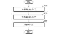
- FIG. 4 is a flowchart showing the basic operation of the airflow generating system according to the embodiment.
- FIG. 5 is a flowchart showing an example of the operation of the airflow generating system according to the embodiment.
- FIG. 6 is a diagram for explaining the operation of the airflow generating device in step S20 of FIG.
- FIG. 7 is a diagram for explaining the first modification of the control process.
- FIG. 8 is a diagram for explaining the second modification of the control process.
- FIG. 9 is a diagram for explaining the third modification of the control process.
- each figure is a schematic diagram and is not necessarily a precise illustration.
- the same reference numerals are used for substantially the same configurations, and duplicate explanations may be omitted or simplified.
- FIG. 1 is a diagram for explaining an overview of an airflow generation system 100 according to an embodiment.
- Fig. 2 is a block diagram showing a functional configuration of the airflow generation system 100 according to an embodiment.
- Fig. 3 is a diagram showing an example of installation of an inside air temperature detection unit 2.
- the airflow generating system 100 detects the outside and inside air temperatures, and controls the airflow generating device 4 that generates an airflow along the structure 3 from one side of the ceiling and floor to the other side based on the detected outside and inside air temperatures. Specifically, the airflow generating system 100 controls the generation of airflow so as to reduce the impact on the inside air temperature of heat (radiant heat and cold radiation) that moves between the outside of the building 50 (i.e., outdoors) and the space 5 inside the building 50 via the structure 3.
- heat radiant heat and cold radiation
- the outside air temperature is the temperature outdoors and is detected by the outside air temperature detection unit 1.
- the inside air temperature is the temperature inside the space 5 separated from the outdoors by the erected structure 3 and is detected by the inside air temperature detection unit 2.
- the structure 3 is, for example, a wall or a window.
- FIG. 1 shows an example in which the structure 3 is a window
- FIG. 3 shows an example in which the structure 3 is a wall.
- the space 5 is, for example, a room separated from the outdoors by a wall or a window.
- the airflow generating system 100 includes an outside air temperature detection unit 1, an inside air temperature detection unit 2, an airflow generating device 4, and a control unit (in this example, a control device 10).
- the outside air temperature detection unit 1 is a sensor that detects the outside air temperature, which is the temperature outdoors.
- the outside air temperature detection unit 1 is, for example, a temperature sensor. There is no particular limitation on the type of temperature sensor.
- the outside air temperature detection unit 1 transmits data on the detected outside air temperature to the control device 10.
- the outside air temperature detection unit 1 is connected to the control device 10, for example, via wireless communication or wired communication.
- the outside air temperature detection unit 1 is installed outdoors near a structure 3.
- the indoor air temperature detection unit 2 is a sensor that detects the indoor air temperature of the space 5 separated from the outdoors by the erected structure 3.
- the indoor air temperature detection unit 2 may be realized by a plurality of temperature sensors distributed in the space 5, or may be realized by a thermal image sensor that captures a thermal image of the space 5.
- the thermal image sensor is, for example, an infrared array sensor or an infrared camera.
- the indoor air temperature detection unit 2 is a thermal image sensor, one indoor air temperature detection unit 2 is installed on the ceiling of the space (see FIG. 1), but two or more indoor air temperature detection units 2 may be installed (see FIG. 3(a)).
- the indoor air temperature detection unit 2 may also be installed on a wall instead of the ceiling, or on the floor instead of the ceiling (see FIG. 3(b)).
- the indoor air temperature detection unit 2 may be attached to an air conditioner installed in the space 5, or may be attached to a light installed on the ceiling, wall, or floor of the space 5.
- the inside air temperature detection unit 2 detects a first inside air temperature in the center of the space 5 and a second inside air temperature in a location closer to the structure 3 (e.g., wall 3 in (a) and (b) of FIG. 3) than the center of the space 5.
- the inside air temperature detection unit 2 also detects a third inside air temperature in a location along the ceiling of the space 5 and a fourth inside air temperature in a location along the floor of the space 5.
- the inside air temperature detection unit 2 transmits data on the detected inside air temperatures (first inside air temperature, second inside air temperature, third inside air temperature, and fourth inside air temperature) to the control device 10.
- the inside air temperature detection unit 2 is connected to the control device 10, for example, via wireless communication or wired communication.
- the airflow generating device 4 is a device that generates an airflow that flows from one of the ceiling and floor of the space to the other, along the structure 3.
- the airflow generating device 4 is communicatively connected to the control device 10, and is controlled based on a control signal output from the control device 10.
- the airflow generating device 4 includes a first airflow generating unit 4a provided on the ceiling of the space 5, and a second airflow generating unit 4b provided on the floor of the space 5. More specifically, as shown in FIG. 1, the first airflow generating unit 4a and the second airflow generating unit 4b are installed on the ceiling and floor on the structure 3 side.
- the first airflow generating unit 4a and the second airflow generating unit 4b may be installed at a predetermined distance (e.g., 5 cm to 10 cm) from the structure 3.
- the first airflow generating unit 4a and the second airflow generating unit 4b may be installed so as to overlap when viewed from above the ceiling, or may be arranged so as to be shifted along the structure 3 so that at least a part of the first airflow generating unit 4a and the second airflow generating unit 4b overlap when viewed from above.
- the first airflow generating unit 4a and the second airflow generating unit 4b may be installed on the ceiling surface and the floor surface, or may be embedded in the ceiling and the floor.
- the shape of the first airflow generating unit 4a and the second airflow generating unit 4b may be, for example, an elongated shape extending along the structure 3 (see FIG. 1), or may be a rectangular or circular shape like a ventilation fan.
- each of the first airflow generating unit 4a and the second airflow generating unit 4b may be installed in the space 5 one by one, or two or more may be installed along the structure 3 in the space 5.
- the first airflow generating unit 4a and the second airflow generating unit 4b each include, for example, an outlet, an inlet, a fan (for example, an impeller and a motor that drives the impeller), piping, and a filter.
- the first airflow generating unit 4a and the second airflow generating unit 4b may each include a single fan that can switch between sucking in and blowing out air, or may each include a fan for sucking in air and a fan for blowing out air.
- the airflow is generated when one of the first airflow generating unit 4a and the second airflow generating unit 4b performs a blowing operation to blow air out to the space 5, and the other of the first airflow generating unit 4a and the second airflow generating unit 4b performs a suction operation to suck air from the space 5.
- the control device 10 is an example of a control unit, and controls the airflow generating device 4 based on the outside air temperature detected by the outside air temperature detection unit 1 and the inside air temperature detected by the inside air temperature detection unit 2.
- the control device 10 includes, for example, a communication unit 11, a control unit 12, and a memory unit 13.
- the control device 10 may further include an operation receiving unit (not shown) and a display unit (not shown).
- the control device 10 is, for example, a controller attached to a wall surface in the space 5, but may also be a controller installed in the building 50 that includes the space 5.
- the communication unit 11 is a communication circuit (or a communication module) for the control device 10 to communicate with the outside air temperature detection unit 1, the inside air temperature detection unit 2, and the airflow generating device 4.
- the communication unit 11 is, for example, a wireless communication circuit that performs wireless communication, but may also be a wired communication circuit that performs wired communication. There are no particular limitations on the communication standard of the communication performed by the communication unit 11.
- the communication unit 11 may perform wireless communication with a user's mobile terminal (not shown). In this case, the communication unit 11 may include a communication circuit that performs short-range wireless communication, a communication circuit that performs wireless communication via a wide area communication network, or both of these communication circuits.
- the mobile terminal may receive instructions from the user and transmit the instructions to the control device 10, or may present a notification from the control device 10 to the user.
- the control unit 12 performs information processing to control the airflow generating device 4 based on the outside air temperature detected by the outside air temperature detection unit 1 and the inside air temperature detected by the inside air temperature detection unit 2.
- the control unit 12 is realized, for example, by a microcomputer, but may also be realized by a processor.
- the control unit 12 has, as functional components, an acquisition unit 12a, a determination unit 12b, and an output unit 12c.
- the functions of the acquisition unit 12a, the determination unit 12b, and the output unit 12c are realized, for example, by the microcomputer or processor constituting the control unit 12 executing a computer program stored in the memory unit 13.
- the memory unit 13 is a storage device that stores information necessary to control the airflow generating device 4. Such information includes computer programs executed by the control unit 12.
- the memory unit 13 is realized, for example, by a semiconductor memory.
- the operation reception unit receives operations (manual operations) by the user of the airflow generating device 4.
- the operation reception unit is realized, for example, by a touch panel, but may also be realized by hardware keys, etc.
- the display unit (not shown) displays images.
- the display unit is realized by a display panel such as a liquid crystal panel or an organic EL (Electro Luminescence) panel.
- FIG. 4 is a flowchart showing the basic operation of the airflow generation system 100 according to the embodiment.
- Fig. 5 is a flowchart showing an example of the operation of the airflow generation system 100 according to the embodiment.
- control unit of the airflow generating system 100 When the control unit of the airflow generating system 100 (here, the control device 10) accepts an operation by a user to input an instruction to start operation, it outputs an instruction to start operation to the outside air temperature detection unit 1, the inside air temperature detection unit 2, and the airflow generating device 4 (not shown).
- the control unit of the airflow generating system 100 here, the control device 10) accepts an operation by a user to input an instruction to start operation and outputs an instruction to start operation, but this is not limited to this example.
- control device 10 of the airflow generating system 100 when the control device 10 of the airflow generating system 100 starts operation (for example, when the program operation starts after power is supplied to the control device 10), it may output an instruction to start operation to the outside air temperature detection unit 1, the inside air temperature detection unit 2, and the airflow generating device 4.
- the outside air temperature detection unit 1 detects the outside air temperature, which is the temperature outdoors (outside air temperature detection step S01 in FIG. 4, step S11 in FIG. 5).
- the outside air temperature detection unit 1 transmits the detected outside air temperature data to the control device 10 at a predetermined time interval.
- the frequency of data transmission may be determined as appropriate.
- the inside air temperature detection unit 2 detects the inside air temperature of the space 5 separated from the outdoors by the erected structure 3 (inside air temperature detection step S02).
- the inside air temperature detection unit 2 transmits the detected inside air temperature data to the control device 10 at a predetermined time interval. The frequency of transmitting the data may be determined appropriately. Note that the outside air temperature detection step S01 and the inside air temperature detection step S02 may be performed in parallel.
- control device 10 of the airflow generating system 100 controls the airflow generating device 4 based on the detected outside and inside air temperatures to generate an airflow that flows from one side of the ceiling and floor of the space 5 to the other side and that follows the structure 3 (control step S03).
- the airflow generating device 4 has been described above, so a description thereof will be omitted here.
- the airflow generating system 100 controls the generation of airflow based on the outside air temperature and the inside air temperature, thereby reducing the impact on the inside air temperature caused by the transfer of heat between the outdoors and the space 5 separated from the outdoors by the structure 3.
- the interior air temperature detection unit 2 detects a first interior air temperature in the center of the space 5 and a second interior air temperature in a location closer to the structure 3 than the center of the space 5 (S12), and transmits the detected first interior air temperature and second interior air temperature data to the control device 10.
- control device 10 When the control device 10 acquires the data of the first and second inside air temperatures sent from the inside air temperature detection unit 2 (not shown), it determines whether the second inside air temperature is closer to the outside air temperature than the first inside air temperature (step S13). When the control device 10 determines that the second inside air temperature is closer to the outside air temperature than the first inside air temperature (Yes in step S13), it outputs an instruction to the airflow generating device 4 to start generating an airflow (not shown). When the airflow generating device 4 acquires the instruction, it starts generating an airflow (step S14). Specific airflow control will be described later.
- the control device 10 determines that the second indoor air temperature is not closer to the outdoor air temperature than the first indoor air temperature (No in step S13), it causes the indoor air temperature detection unit 2 to detect a third indoor air temperature at a location along the ceiling of space 5 and a fourth indoor air temperature at a location along the floor of space 5.
- the indoor air temperature detection unit 2 detects the third indoor air temperature and the fourth indoor air temperature (step S15)
- control device 10 When the control device 10 acquires the data of the third and fourth internal temperatures sent from the internal temperature detection unit 2 (not shown), it determines whether the absolute value of the difference between the third and fourth internal temperatures is equal to or greater than the second threshold (step S16). When the control device 10 determines that the absolute value of the difference between the third and fourth internal temperatures is not equal to or greater than the second threshold (No in step S16), it returns to the processing of step S11. On the other hand, when the control device 10 determines that the absolute value of the difference between the third and fourth internal temperatures is equal to or greater than the second threshold (Yes in step S16), it outputs an instruction to the airflow generating device 4 to start generating an airflow (not shown). When the airflow generating device 4 acquires the instruction, it starts generating an airflow (step S14).
- the control device 10 judges whether the absolute value of the difference between the first and second internal temperatures is equal to or less than a first threshold value (e.g., 2) at predetermined time intervals (e.g., 5 minutes) (step S17).
- a first threshold value e.g. 2
- predetermined time intervals e.g. 5 minutes
- the internal temperature detection unit 2 transmits data on the detected internal temperatures to the control device 10 at predetermined time intervals.
- the control device 10 makes the above judgment based on the time series data of the acquired internal temperatures (here, the first internal temperature and the second internal temperature).
- control device 10 judges that the absolute value of the difference between the first and second internal temperatures is equal to or less than the first threshold value (Yes in step S17), it outputs an instruction to the airflow generating device 4 to stop generating the airflow (not shown).
- the airflow generating device 4 receives the instruction, it stops generating the airflow (step S18). In other words, the control device 10 causes the airflow generating device 4 to continue generating the airflow from the start of airflow generation in step S14 until the absolute value of the difference between the first and second internal temperatures is equal to or less than the first threshold value.
- control device 10 When the control device 10 receives an operation by the user to input an instruction to end operation, it outputs an instruction to end operation to the outside air temperature detection unit 1, the inside air temperature detection unit 2, and the airflow generation device 4, and ends the operation of the outside air temperature detection unit 1, the inside air temperature detection unit 2, and the airflow generation device 4 (not shown), but these operations may also be ended by the processing of step S18.
- control device 10 determines whether or not it is within a first time (e.g., 10 minutes) since the airflow generation started (step S19).
- a first time e.g. 10 minutes
- the control device 10 determines that it is within the first time since the airflow generation started (Yes in step S19)
- it outputs an instruction to the airflow generating device 4 to (i) gradually increase the strength of the airflow, (ii) reverse the direction of the airflow, or (iii) cause the first airflow generating unit 4a and the second airflow generating unit 4b to perform the same operation (e.g., blowing or suctioning) (not shown).
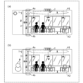
- FIG. 6 is a diagram for explaining the operation of the airflow generating device 4 in step S20 of FIG. 5.
- the reference numeral 4 is omitted from the illustration in view of ease of viewing. (a) and (b) of FIG.
- FIG. 6 are diagrams that show a schematic example of the airflow generating device 4 reversing the direction of the airflow as described above in (ii), and (c) and (d) of FIG. 6 are diagrams that show a schematic example of the first airflow generating unit 4a and the second airflow generating unit 4b performing the same operation as described above in (iii).
- the structure 3 is a wall, and the operation of the first airflow generating unit 4a and the second airflow generating unit 4b to blow air into the space 5 and to suck air from the space 5 are shown by outlined arrows.
- the airflow generating device 4 when the airflow generating device 4 receives an instruction from the control device 10 to reverse the direction of the airflow, the first airflow generating unit 4a switches from the blowing operation to the suction operation and the second airflow generating unit 4b switches from the suction operation to the blowing operation in accordance with the instruction, thereby reversing the direction of the airflow, as shown in FIG. 6B. As a result, the airflow generating device 4 reverses the airflow from the ceiling side to the floor side and generates an airflow from the floor side to the ceiling side.
- both the first airflow generating unit 4a and the second airflow generating unit 4b perform a blowing operation in accordance with the instruction, as shown in (c) of FIG. 6.
- This allows the airflow generating system 100 to push the air near the structure 3 (e.g., the wall 3) of the space 5 toward the center of the space 5, thereby circulating the air, making it easier to make the absolute value of the difference between the first and second internal air temperatures approach the first threshold value or less.
- both the first airflow generating unit 4a and the second airflow generating unit 4b perform a suction operation in accordance with the instruction, as shown in (d) of FIG. 6.
- the airflow generating system 100 can draw air closer to the center of the space 5 to a location closer to the structure 3 (wall 3) of the space 5 and circulate the air, making it easier to bring the absolute value of the difference between the first and second internal temperatures closer to or less than the first threshold value.
- step S20 the control device 10 of the airflow generating system 100 returns to step S17.
- the control device 10 determines whether it is within the first hour since the airflow generation started (No in step S19)
- the second time is longer than the first time.
- the first time is 10 minutes and the second time is 60 minutes, but this example is not limited to this example. These times may vary depending on, for example, the amount of moisture contained in the air and the temperature of the air, and may be set experimentally or empirically.
- control device 10 determines that it is within the second hour since the airflow generation started (Yes in step S21), it returns to step S17. On the other hand, if the control device 10 determines that it is not within the second hour since the airflow generation started (No in step S21), it outputs an instruction to the airflow generating device 4 to stop the generation of the airflow (not shown). When the airflow generating device 4 receives the instruction, it stops the generation of the airflow (step S18).
- the airflow generating system 100 starts generating airflow when heat transfer between the outdoors and the space 5 occurs through the structure 3 (wall 3), thereby reducing the impact of the heat transfer on the inside air temperature.
- the airflow generating system 100 can reduce the impact of heat transfer between the outdoors and the space 5 on the inside air temperature by continuing to generate airflow until the temperature difference between the center of the space 5 and the area close to the structure 3 (wall 3) is small enough that there is almost no difference in the temperature felt by people. Therefore, the airflow generating system 100 can provide a comfortable air-conditioned environment for people in the space 5.
- the airflow generating system 100 can gradually increase the strength of the airflow after a first time (e.g., 10 minutes) has elapsed, or reverse the direction of the airflow, or have both the first airflow generating unit 4a and the second airflow generating unit 4b perform the same operation (specifically, a blowing operation or a suction operation), thereby making it possible to bring the difference closer to a temperature difference that does not change the temperature felt by people in a shorter time. Therefore, the airflow generating system 100 can provide a comfortable air-conditioned environment for people in the space 5, even if it is difficult to reduce the impact of the transfer of heat between the outdoors and the space 5 on the inside temperature.
- a first time e.g. 10 minutes
- the airflow generating system 100 can reduce the load and cost of the airflow generating device 4 by stopping the generation of the airflow.
- the airflow generating system 100 starts generating an airflow when either a warm air pocket occurs along the ceiling of the space 5, or a cold air pocket occurs along the floor of the space 5, so that it is possible to reduce the impact of heat transfer between the outdoors and the space 5 on the internal air temperature by using either the air at the third internal temperature in the warm air pocket or the air at the fourth internal temperature in the cold air pocket.
- FIG. 7 is a diagram for explaining the first modified example of the control process.
- the structure 3 is a wall, and the airflow generated along the structure 3 (e.g., the wall 3) by the operation of the first airflow generation unit 4a and the second airflow generation unit 4b is shown by outlined arrows.
- the transfer of heat between the outdoors and the inside of the space 5, which occurs via the structure 3 (wall 3) is shown by dotted arrows.
- the control device 10 acquires the outside air temperature detected by the outside air temperature detection unit 1 and the inside air temperature detected by the inside air temperature detection unit 2, and when the outside air temperature is higher than the inside air temperature, the control device 10 causes the airflow generating device 4 to generate an airflow from the floor to the ceiling, for example, as shown in FIG. 7(a).
- the control device 10 causes the airflow generating device 4 to generate an airflow from the ceiling to the floor, for example, as shown in FIG. 7(b).
- the inside air temperature may be the second inside air temperature in the center of the space 5, or may be the first inside air temperature in a location closer to the structure 3 (wall 3) of the space 5.
- the airflow generating system 100 can generate an airflow toward the ceiling by using air at the fourth inside temperature in the cold air reservoir A2 located along the floor of the space 5, and when the outside temperature is lower than the inside temperature, the airflow generating system 100 can generate an airflow toward the floor by using air at the third inside temperature in the warm air reservoir A1 located along the ceiling of the space 5. This allows the airflow generating system 100 to block the transfer of heat (radiant heat or cold radiation) between the outdoors and the space 5, thereby reducing the impact of the transfer of heat on the inside temperature.
- heat radiant heat or cold radiation
- FIG. 8 is a diagram for explaining the second modified example of the control process.
- the structure 3 is a wall, and the airflow generated along the structure 3 (e.g., the wall 3) by the operation of the first airflow generation unit 4a and the second airflow generation unit 4b is shown by outlined arrows.
- the convection generated along the structure 3 (wall 3) by the transfer of heat between the outdoors and the inside of the space 5 is shown by dotted arrows.
- the control device 10 acquires the outside air temperature detected by the outside air temperature detection unit 1 and the inside air temperature detected by the inside air temperature detection unit 2, and when the outside air temperature is higher than the inside air temperature, the control device 10 causes the airflow generating device 4 to generate an airflow from the ceiling to the floor, for example, as shown in FIG. 8(a).
- the control device 10 causes the airflow generating device 4 to generate an airflow from the floor to the ceiling, for example, as shown in FIG. 8(b).
- the inside air temperature may be the second inside air temperature in the center of the space 5, or may be the first inside air temperature in a location near the structure 3 (wall 3) of the space 5.
- the airflow generating system 100 can generate an airflow toward the floor by using air at the third inside temperature in the warm air reservoir A1 located along the ceiling of the space 5, and when the outside temperature is lower than the inside temperature, the airflow generating system 100 can generate an airflow toward the ceiling by using air at the fourth inside temperature in the cold air reservoir A2 located along the floor of the space 5.
- This allows the airflow generating system 100 to counteract the convection of warm or cold air that occurs along the structure 3 (wall 3) due to the transfer of heat (radiant heat or cold radiation) between the outdoors and the space 5, thereby reducing the impact of the transfer of heat on the inside temperature.
- FIG. 9 is a diagram for explaining Modification 3 of the control process.
- the structure 3 is a wall, and the airflows generated by the operation of the first airflow generation unit 4a and the second airflow generation unit 4b are indicated by outlined arrows.
- the distance of the first airflow generating unit 4a from the structure 3 (e.g., the wall 3) and the distance of the second airflow generating unit 4b from the structure 3 can be set individually.
- the distance from the structure 3 (wall 3) to the center of the first airflow generating unit 4a of the first airflow generating unit 4a provided on the ceiling of the space 5 is X1
- the distance from the structure 3 (wall 3) to the center of the second airflow generating unit 4b of the second airflow generating unit 4b provided on the floor of the space 5 is X2 .
- X1 and X2 can take may be, for example, 0 cm or more and 30 cm or less. These ranges are not particularly limited to the above example, and may be set appropriately depending on the size of the first airflow generating unit 4a and the second airflow generating unit 4b. These ranges may be set experimentally or empirically.
- the above X1 and X2 are the distance from the structure 3 (wall 3) to the center of the first airflow generating unit 4a and the distance from the structure 3 to the center of the second airflow generating unit 4b, but they do not have to be the centers.
- X1 may be the distance from the structure 3 (wall 3) to the end (side) of the first airflow generating unit 4a on the structure 3 (wall 3) side
- X2 may be the distance from the structure 3 (wall 3) to the end (side) of the second airflow generating unit 4b on the structure 3 (wall 3) side.
- Each of the first airflow generating unit 4a and the second airflow generating unit 4b can perform a blowing operation to send air into the space 5 and a suction operation to suck air from the space 5, and the blowing direction of the air in the blowing operation and the suction direction of the air in the suction operation are variable.
- the control device 10 causes both the first airflow generating unit 4a and the second airflow generating unit 4b to perform a blowing operation, but may also cause them to perform a suction operation.
- the control device 10 causes the first airflow generating unit 4a to perform a blowing operation and the second airflow generating unit 4b to perform a suction operation.
- the first airflow generating unit 4a changes the blowing direction of the air in the blowing operation to the direction of the second airflow generating unit 4b
- the second airflow generating unit 4b changes the suction direction of the air in the suction operation to the direction of the first airflow generating unit 4a.
- the control device 10 causes the first airflow generating unit 4a to perform a suction operation and the second airflow generating unit 4b to perform a blowing operation.
- the first airflow generating unit 4a changes the air suction direction during the suction operation to the direction of the second airflow generating unit 4b
- the second airflow generating unit 4b changes the air blowing direction during the blowing operation to the direction of the first airflow generating unit 4a.
- the airflow generating system 100 can be installed so that the first airflow generating unit 4a and the second airflow generating unit 4b overlap when viewed from above the ceiling, or can be installed with their positions shifted so as not to overlap from the structure 3 (wall 3) toward the center of the space 5. Therefore, the airflow generating system 100 can generate an airflow or convection of a desired width in the direction from the structure 3 (wall 3) to the center of the space 5. Therefore, the airflow generating system 100 can efficiently reduce the influence of the transfer of heat between the outdoors and the space 5 on the inside air temperature.
- the airflow generating system 100 can generate airflows that do not hit the structure 3 (wall 3) because the blowing direction of the air in the blowing operation of the first airflow generating unit 4a and the second airflow generating unit 4b and the sucking direction of the air in the sucking operation are variable. Therefore, the airflow generating system 100 can make it difficult for condensation to occur on the surface of the structure 3 (wall 3). Therefore, the airflow generating system 100 can provide a comfortable environment for people present in the space 5.
- Invention 1 is an airflow generating system 100 comprising an outside air temperature detection unit 1 that detects the outside air temperature, which is the temperature outdoors (e.g., outside a building 50), an inside air temperature detection unit 2 that detects the inside air temperature of a space 5 separated from the outdoors by an upright structure 3, an airflow generating device 4 that generates an airflow along the structure 3, which is an airflow from one side of the ceiling and floor of the space 5 to the other, and a control unit (e.g., control device 10) that controls the airflow generating device 4 based on the detected outside and inside air temperatures.
- an outside air temperature detection unit 1 that detects the outside air temperature, which is the temperature outdoors (e.g., outside a building 50)
- an inside air temperature detection unit 2 that detects the inside air temperature of a space 5 separated from the outdoors by an upright structure 3
- an airflow generating device 4 that generates an airflow along the structure 3, which is an airflow from one side of the ceiling and floor of the space 5 to the other
- This type of airflow generating system 100 controls the generation of airflow based on the outside air temperature and the inside air temperature, so it can reduce the impact on the inside air temperature caused by the transfer of heat between the outdoors and the space 5 separated from the outdoors by the structure 3.
- Invention 2 is the airflow generating system 100 of Invention 1, in which the internal air temperature detection unit 2 detects a first internal air temperature in the center of the space 5 and a second internal air temperature in a location closer to the structure 3 than the center of the space 5, and the control device 10 causes the airflow generating device 4 to start generating an airflow when the second internal air temperature is closer to the outside air temperature than the first internal air temperature.
- This type of airflow generating system 100 starts generating airflow when heat transfer between the outdoors and the space 5 occurs through the structure 3, reducing the impact of the heat transfer on the inside air temperature.
- control device 10 causes the airflow generating device 4 to continue generating an airflow until the absolute value of the difference between the first internal air temperature and the second internal air temperature becomes equal to or less than a first threshold value (e.g., 2) after the airflow generation is started.
- a first threshold value e.g. 2, 2
- Such an airflow generating system 100 can reduce the impact of heat transfer between the outdoors and space 5 on the inside air temperature by continuing to generate airflow until the temperature difference between the center of space 5 and the area close to structure 3 is small enough that there is almost no difference in the temperature felt by people. Therefore, airflow generating system 100 can provide a comfortable air-conditioned environment for people in space 5.
- control device 10 controls the airflow generating device 4 to gradually increase the strength of the airflow if the absolute value of the difference does not become equal to or less than a first threshold value (e.g., 2) within a first time (e.g., 10 minutes) after the airflow generation is started.
- a first threshold value e.g. 2
- a first time e.g. 10 minutes
- Such an airflow generating system 100 can gradually increase the strength of the airflow after a first time (e.g., 10 minutes) has elapsed, thereby bringing the difference closer to a temperature difference that does not change the temperature felt by people in a shorter time. Therefore, the airflow generating system 100 can provide a comfortable air-conditioned environment for people in the space 5, even in cases where it is difficult to reduce the impact of the transfer of heat between the outdoors and the space 5 on the inside air temperature.
- a first time e.g. 10 minutes
- control device 10 controls the airflow generating device 4 to reverse the direction of the airflow if the absolute value of the difference does not become equal to or less than a first threshold value (e.g., 2) within a first time (e.g., 10 minutes) after the airflow generation starts.
- a first threshold value e.g., 2
- a first time e.g. 10 minutes
- Such an airflow generating system 100 can reverse the direction of the airflow after a first time (e.g., 10 minutes) has elapsed, and by using, for example, the air along the ceiling of the space 5 or the air along the floor of the space 5, the difference can be brought closer to a temperature difference that does not change the temperature felt by people. Therefore, the airflow generating system 100 can provide a comfortable air-conditioned environment for people in the space 5, even if it is difficult to reduce the impact of the transfer of heat between the outdoors and the space 5 on the inside air temperature.
- a first time e.g. 10 minutes
- the airflow generating device 4 includes a first airflow generating unit 4a provided on the ceiling of the space 5 and a second airflow generating unit 4b provided on the floor of the space 5, the airflow is generated when one of the first airflow generating unit 4a and the second airflow generating unit 4b performs a blowing operation to blow air into the space 5 and the other of the first airflow generating unit 4a and the second airflow generating unit 4b performs a suction operation to suck air from the space 5, and the control device 10 causes both the first airflow generating unit 4a and the second airflow generating unit 4b to perform a blowing operation or causes both the first airflow generating unit 4a and the second airflow generating unit 4b to perform a suction operation if the absolute value of the difference does not become equal to or less than a first threshold value (e.g., 2) within a first time (e.g., 10 minutes) after the airflow generation is started.
- a first threshold value e.g., 2
- Such an airflow generating system 100 can generate air convection in a location along the structure 3 in the space 5 by having both the first airflow generating unit 4a and the second airflow generating unit 4b perform the same operation (blowing or suction operation). As a result, air is drawn from other locations in the space 5 (e.g., locations along the ceiling, the floor, and the center) to the location along the structure 3 in the space 5, making it easier for the difference to approach the first threshold value or less. Therefore, the airflow generating system 100 can provide a comfortable air-conditioned environment for people in the space 5 even in cases where it is difficult to reduce the effect of heat transfer between the outdoors and the space 5 on the inside temperature.
- control device 10 causes the airflow generating device 4 to stop generating the airflow if the absolute value of the difference does not become within a first threshold value (e.g., 2) within a second time (e.g., 60 minutes) after the airflow generation is started, and the second time is longer than the first time, in the airflow generating system 100 of any of inventions 4 to 6.
- a first threshold value e.g. 2
- a second time e.g. 60 minutes
- Such an airflow generating system 100 can reduce the load and cost of the airflow generating device 4 by stopping the generation of the airflow when it is difficult to reduce the impact of the heat transfer between the outdoors and the space 5 on the inside air temperature within the second time period (e.g., 60 minutes).
- Invention 8 is the airflow generating system 100 of Invention 2, in which the indoor air temperature detection unit 2 detects a third indoor air temperature at a location along the ceiling of the space 5 and a fourth indoor air temperature at a location along the floor of the space 5, and the control device 10 causes the airflow generating device 4 to start generating an airflow when the absolute value of the difference between the third indoor air temperature and the fourth indoor air temperature is equal to or greater than a second threshold value (e.g., 5).
- a second threshold value e.g., 5
- Such an airflow generating system 100 starts generating an airflow when either a warm air pocket occurs along the ceiling of space 5 or a cold air pocket occurs along the floor of space 5, and can therefore utilize either the air at the third internal temperature in the warm air pocket or the air at the fourth internal temperature in the cold air pocket to reduce the impact of heat transfer between the outdoors and space 5 on the internal temperature.
- Invention 9 is the airflow generating system 100 of invention 1, in which the control device 10 causes the airflow generating device 4 to generate an airflow from the floor to the ceiling when the outside air temperature is higher than the inside air temperature, and causes the airflow generating device 4 to generate an airflow from the ceiling to the floor when the outside air temperature is lower than the inside air temperature.
- Such an airflow generating system 100 can generate an airflow toward the ceiling by using air of a fourth internal temperature in a cold air reservoir along the floor of space 5 when the outside temperature is higher than the inside temperature, and can generate an airflow toward the floor by using air of a third internal temperature in a warm air reservoir along the ceiling of space 5 when the outside temperature is lower than the inside temperature. This allows the airflow generating system 100 to block the transfer of heat (radiant heat or cold radiation) between the outdoors and space 5, thereby reducing the impact of the transfer of heat on the inside temperature.
- control device 10 controls the airflow generating device 4 to generate an airflow from the ceiling to the floor when the outside air temperature is higher than the inside air temperature, and controls the airflow generating device 4 to generate an airflow from the floor to the ceiling when the outside air temperature is lower than the inside air temperature.
- Such an airflow generating system 100 can generate an airflow toward the floor by using air of a third internal temperature in a warm air reservoir located along the ceiling of space 5 when the outside temperature is higher than the inside temperature, and can generate an airflow toward the ceiling by using air of a fourth internal temperature in a cold air reservoir located along the floor of space 5 when the outside temperature is lower than the inside temperature. This allows the airflow generating system 100 to cancel out the convection of warm or cold air that occurs along the structure 3 due to the transfer of heat (radiant heat or cold radiation) between the outdoors and space 5, thereby reducing the impact of the transfer of heat on the inside temperature.
- the airflow generating device 4 includes a first airflow generating unit 4a provided on the ceiling of the space 5 and a second airflow generating unit 4b provided on the floor of the space 5, and each of the first airflow generating unit 4a and the second airflow generating unit 4b can perform a blowing operation to send air into the space 5 and a suction operation to suck air from the space 5, the blowing direction of the air in the blowing operation and the suction direction of the air in the suction operation are variable, and the distance of the first airflow generating unit 4a from the structure 3 and the distance of the second airflow generating unit 4b from the structure 3 can be set individually, in the airflow generating system 100 of any of inventions 1 to 10.
- the first airflow generating unit 4a and the second airflow generating unit 4b can be installed so as to overlap when viewed from above from the ceiling, or can be installed so as to be offset from the structure 3 toward the center of the space 5 so as not to overlap. Therefore, the airflow generating system 100 can generate an airflow or convection of a desired width in the direction from the structure 3 to the center of the space 5. Therefore, the airflow generating system 100 can efficiently reduce the influence of the transfer of heat between the outdoors and the space 5 on the inside air temperature.
- the airflow generating system 100 can change the blowing direction of the air in the blowing operation of the first airflow generating unit 4a and the second airflow generating unit 4b and the sucking direction of the air in the sucking operation, the airflow can be generated so as not to hit the structure 3. Therefore, the airflow generating system 100 can make it difficult for condensation to occur on the surface of the structure 3. Therefore, the airflow generating system 100 can provide a comfortable environment for people in the space 5.
- the airflow generating device 4 includes a first airflow generating unit 4a provided on the ceiling of the space 5 and a second airflow generating unit 4b provided on the floor of the space 5, and the control device 10 causes one of the first airflow generating unit 4a and the second airflow generating unit 4b to perform a blowing operation to send air into the space 5 and causes the other of the first airflow generating unit 4a and the second airflow generating unit 4b to perform a suction operation to suck air from the space 5, while the distance of the first airflow generating unit 4a from the structure 3 and the distance of the second airflow generating unit 4b from the structure 3 are different, thereby causing the airflow generating device 4 to generate an airflow.
- the first airflow generating unit 4a and the second airflow generating unit 4b are installed so as not to overlap from the structure 3 toward the center of the space 5 when viewed from above from the ceiling, and an airflow heading from the first airflow generating unit 4a to the second airflow generating unit 4b, or an airflow heading from the second airflow generating unit 4b to the first airflow generating unit 4a, can be generated. Therefore, the airflow generating system 100 uses the air in the warm air pocket along the ceiling, or the air in the cold air pocket along the floor, to move air in a location along the structure 3, thereby reducing the impact of heat transfer between the outdoors and the space 5 on the internal temperature, and eliminating the warm air pocket and the cold air pocket.
- Invention 13 is an airflow generating system 100 according to any one of Inventions 1 to 12, in which the structure 3 is a wall or a window.
- Such an airflow generating system 100 can reduce the impact on the inside air temperature caused by heat transfer between the outdoors and a space 5 separated from the outdoors by a wall or window.
- Invention 14 is an airflow generating system 100 according to any one of Inventions 1 to 13, in which the inside air temperature detection unit 2 includes a plurality of temperature sensors distributed in the space 5.
- Such an airflow generating system 100 can acquire temperature distribution data within the space 5 based on the internal air temperatures at multiple locations in the space 5 detected by multiple temperature sensors.
- Invention 15 is an airflow generating system 100 according to any one of Inventions 1 to 13, in which the inside air temperature detection unit 2 includes a thermal image sensor that captures a thermal image of the space 5.
- Such an airflow generating system 100 can obtain temperature distribution data within the space 5 based on the thermal image simply by installing one thermal image sensor in the space 5 that captures a thermal image of the space 5.
- Invention 16 is an airflow generating method executed by a computer such as the airflow generating system 100, and includes an outside air temperature detection step S01 for detecting the outside air temperature, which is the temperature outdoors (outside the building 50), an inside air temperature detection step S02 for detecting the inside air temperature of a space 5 separated from the outdoors by an erected structure 3, and a control step S03 for controlling the airflow generating device 4 based on the detected outside and inside air temperatures to generate an airflow that flows from one side of the ceiling and floor of the space 5 to the other and that follows the structure 3.
- an outside air temperature detection step S01 for detecting the outside air temperature, which is the temperature outdoors (outside the building 50)
- an inside air temperature detection step S02 for detecting the inside air temperature of a space 5 separated from the outdoors by an erected structure 3
- a control step S03 for controlling the airflow generating device 4 based on the detected outside and inside air temperatures to generate an airflow that flows from one side of the ceiling and floor of the space 5 to the other and that
- This airflow generation method can cause the airflow generating device 4 to generate an airflow in a specified direction along the structure 3 based on the outside air temperature and the inside air temperature, thereby reducing the impact on the inside air temperature caused by the transfer of heat between the outdoors and the space 5 separated from the outdoors by the structure 3.
- Invention 17 is a program for causing a computer to execute the airflow generation method of invention 16.
- Such a program can cause the airflow generating device 4 to generate an airflow in a specified direction along the structure 3 based on the outside and inside temperatures, thereby reducing the impact on the inside temperature caused by the transfer of heat between the outdoors and the space 5 separated from the outdoors by the structure 3.
- the airflow generation system may be realized by a single device, or may be realized by multiple devices.
- the airflow generation system may be realized as a single device corresponding to the control device.
- the components (particularly functional components) of the airflow generation system may be allocated in any way to the multiple devices.
- the functional components (acquisition unit, determination unit, output unit) of the control device may be included in the airflow generation device.
- the method of communication between the devices in the above embodiment is not particularly limited.
- a relay device (not shown) may be used in the communication between the devices.
- processing performed by a specific processing unit may be executed by another processing unit.
- the order of multiple processes may be changed, and multiple processes may be executed in parallel.
- each component may be realized by executing a software program suitable for each component.
- Each component may be realized by a program execution unit such as a CPU or processor reading and executing a software program recorded on a recording medium such as a hard disk or semiconductor memory.
- each component may be realized by hardware.
- each component may be a circuit (or an integrated circuit). These circuits may form a single circuit as a whole, or each may be a separate circuit. Furthermore, each of these circuits may be a general-purpose circuit, or a dedicated circuit.
- the general or specific aspects of the present invention may be realized as a system, an apparatus, a method, an integrated circuit, a computer program, or a computer-readable recording medium such as a CD-ROM.
- the present invention may be realized as any combination of a system, an apparatus, a method, an integrated circuit, a computer program, and a recording medium.
- the present invention may be realized as an airflow generating device or control device according to the above-described embodiments.
- the present invention may also be realized as an airflow generating method executed by a computer, such as an airflow generating system, or as a program for causing a computer to execute such an airflow generating method.
- the present invention may also be realized as a computer-readable non-transitory recording medium on which such a program is recorded.
- the present invention also includes forms obtained by applying various modifications to each embodiment that a person skilled in the art may conceive, or forms realized by arbitrarily combining the components and functions of each embodiment within the scope of the spirit of the present invention.
- Airflow generating system 1 Outside temperature detector 2 Inside temperature detector 3 Structure (wall) 4 Airflow generating device 4a First airflow generating section 4b Second airflow generating section 5 Space 10 Control device 100 Airflow generating system
Landscapes
- Engineering & Computer Science (AREA)
- Chemical & Material Sciences (AREA)
- Combustion & Propulsion (AREA)
- Mechanical Engineering (AREA)
- General Engineering & Computer Science (AREA)
- Air Conditioning Control Device (AREA)
Priority Applications (2)
| Application Number | Priority Date | Filing Date | Title |
|---|---|---|---|
| EP23906519.6A EP4641101A4 (en) | 2022-12-19 | 2023-11-10 | AIR FLOW PRODUCTION SYSTEM, AIR FLOW PRODUCTION PROCESS AND PROGRAM |
| JP2024565666A JPWO2024135148A1 (https=) | 2022-12-19 | 2023-11-10 |
Applications Claiming Priority (2)
| Application Number | Priority Date | Filing Date | Title |
|---|---|---|---|
| JP2022-202200 | 2022-12-19 | ||
| JP2022202200 | 2022-12-19 |
Publications (1)
| Publication Number | Publication Date |
|---|---|
| WO2024135148A1 true WO2024135148A1 (ja) | 2024-06-27 |
Family
ID=91588514
Family Applications (1)
| Application Number | Title | Priority Date | Filing Date |
|---|---|---|---|
| PCT/JP2023/040509 Ceased WO2024135148A1 (ja) | 2022-12-19 | 2023-11-10 | 気流発生システム、気流発生方法、および、プログラム |
Country Status (3)
| Country | Link |
|---|---|
| EP (1) | EP4641101A4 (https=) |
| JP (1) | JPWO2024135148A1 (https=) |
| WO (1) | WO2024135148A1 (https=) |
Citations (12)
| Publication number | Priority date | Publication date | Assignee | Title |
|---|---|---|---|---|
| JPS62119342A (ja) * | 1985-11-19 | 1987-05-30 | Shisutetsuku Kankyo Kenkyusho:Kk | エア・カ−テン付き窓 |
| JPH08121815A (ja) * | 1994-10-21 | 1996-05-17 | Shimizu Corp | 空調設備 |
| JPH1038345A (ja) * | 1996-07-22 | 1998-02-13 | Taikisha Ltd | 空調設備 |
| JPH10288380A (ja) * | 1997-04-11 | 1998-10-27 | Toshiba Corp | 空調制御方法および装置 |
| JP2002089947A (ja) * | 2000-09-12 | 2002-03-27 | Takenaka Komuten Co Ltd | ペリメータ空調システム |
| JP2004020087A (ja) * | 2002-06-18 | 2004-01-22 | Taisei Corp | 窓際のエアバリアシステム |
| JP2004271092A (ja) * | 2003-03-10 | 2004-09-30 | Osaka Gas Co Ltd | シーリングファン装置、及び、それを用いた空調設備 |
| JP2006064258A (ja) * | 2004-08-26 | 2006-03-09 | Daikin Ind Ltd | 空気調和システム、空調制御装置および空調制御方法 |
| JP2008298400A (ja) | 2007-06-01 | 2008-12-11 | Sanki Service:Kk | エアカーテン装置及び断熱方法 |
| US20160290673A1 (en) * | 2015-04-01 | 2016-10-06 | Samsung Electronics Co., Ltd. | Apparatus and method for adaptively applying central hvac system and individual hvac system |
| WO2020075244A1 (ja) * | 2018-10-10 | 2020-04-16 | 三菱電機株式会社 | 空気調和機、空気調和機制御方法及びプログラム |
| JP2022157921A (ja) * | 2021-03-31 | 2022-10-14 | 三機工業株式会社 | 空調システム |
Family Cites Families (3)
| Publication number | Priority date | Publication date | Assignee | Title |
|---|---|---|---|---|
| JPH08270977A (ja) * | 1995-01-30 | 1996-10-18 | Nippon Steel Corp | 空調設備 |
| JPH10220839A (ja) * | 1997-01-31 | 1998-08-21 | Shin Nippon Kucho Kk | 窓面の熱処理装置およびその運転方法 |
| CN117222851A (zh) * | 2021-03-31 | 2023-12-12 | 三菱电机楼宇解决方案株式会社 | 空调系统 |
-
2023
- 2023-11-10 JP JP2024565666A patent/JPWO2024135148A1/ja active Pending
- 2023-11-10 EP EP23906519.6A patent/EP4641101A4/en active Pending
- 2023-11-10 WO PCT/JP2023/040509 patent/WO2024135148A1/ja not_active Ceased
Patent Citations (12)
| Publication number | Priority date | Publication date | Assignee | Title |
|---|---|---|---|---|
| JPS62119342A (ja) * | 1985-11-19 | 1987-05-30 | Shisutetsuku Kankyo Kenkyusho:Kk | エア・カ−テン付き窓 |
| JPH08121815A (ja) * | 1994-10-21 | 1996-05-17 | Shimizu Corp | 空調設備 |
| JPH1038345A (ja) * | 1996-07-22 | 1998-02-13 | Taikisha Ltd | 空調設備 |
| JPH10288380A (ja) * | 1997-04-11 | 1998-10-27 | Toshiba Corp | 空調制御方法および装置 |
| JP2002089947A (ja) * | 2000-09-12 | 2002-03-27 | Takenaka Komuten Co Ltd | ペリメータ空調システム |
| JP2004020087A (ja) * | 2002-06-18 | 2004-01-22 | Taisei Corp | 窓際のエアバリアシステム |
| JP2004271092A (ja) * | 2003-03-10 | 2004-09-30 | Osaka Gas Co Ltd | シーリングファン装置、及び、それを用いた空調設備 |
| JP2006064258A (ja) * | 2004-08-26 | 2006-03-09 | Daikin Ind Ltd | 空気調和システム、空調制御装置および空調制御方法 |
| JP2008298400A (ja) | 2007-06-01 | 2008-12-11 | Sanki Service:Kk | エアカーテン装置及び断熱方法 |
| US20160290673A1 (en) * | 2015-04-01 | 2016-10-06 | Samsung Electronics Co., Ltd. | Apparatus and method for adaptively applying central hvac system and individual hvac system |
| WO2020075244A1 (ja) * | 2018-10-10 | 2020-04-16 | 三菱電機株式会社 | 空気調和機、空気調和機制御方法及びプログラム |
| JP2022157921A (ja) * | 2021-03-31 | 2022-10-14 | 三機工業株式会社 | 空調システム |
Non-Patent Citations (1)
| Title |
|---|
| See also references of EP4641101A4 |
Also Published As
| Publication number | Publication date |
|---|---|
| JPWO2024135148A1 (https=) | 2024-06-27 |
| EP4641101A4 (en) | 2026-04-01 |
| EP4641101A1 (en) | 2025-10-29 |
Similar Documents
| Publication | Publication Date | Title |
|---|---|---|
| JP5932998B2 (ja) | 空気調和システム | |
| JP6494562B2 (ja) | 制御装置、空調システム、制御方法、及び、プログラム | |
| CN113906260B (zh) | 空调控制装置以及空调控制系统 | |
| JP6250076B2 (ja) | 空調制御装置、空調制御システム、空調制御方法及びプログラム | |
| JP7330298B2 (ja) | 空気調和システム | |
| JP7004508B2 (ja) | 空調制御装置、空気調和機、空調システム、空調制御方法およびプログラム | |
| JP5725114B2 (ja) | 空調システム | |
| JP2012013389A (ja) | サーキュレータおよびサーキュレータシステム | |
| JP2014035115A (ja) | 空気調和機 | |
| JP6371640B2 (ja) | 空調制御装置および方法 | |
| JP7377333B2 (ja) | 空気調和機 | |
| JP6288138B2 (ja) | 制御装置 | |
| WO2017154060A1 (ja) | 空調送風制御装置 | |
| WO2024135148A1 (ja) | 気流発生システム、気流発生方法、および、プログラム | |
| JP6537705B2 (ja) | 制御装置、空調システム、空調方法及びプログラム | |
| JP6458181B2 (ja) | 空調制御装置および方法 | |
| WO2017081721A1 (ja) | 空調制御システム | |
| JP7588295B2 (ja) | 空調システム | |
| JP6698959B2 (ja) | コントローラ、輻射空気調和設備、制御方法および制御プログラム | |
| JP7535976B2 (ja) | 空気調和システム | |
| JP2017223393A (ja) | 空調制御システム、及び、空調制御方法 | |
| JP7082310B2 (ja) | 空調システム | |
| WO2021234770A1 (ja) | 制御システム、設備機器システム及び設備機器の制御方法 | |
| JP2004293850A (ja) | 屋内の空気流通システム | |
| JP7565483B2 (ja) | 在不在判定装置、換気システム、全館空調システム、監視システム |
Legal Events
| Date | Code | Title | Description |
|---|---|---|---|
| 121 | Ep: the epo has been informed by wipo that ep was designated in this application |
Ref document number: 23906519 Country of ref document: EP Kind code of ref document: A1 |
|
| WWE | Wipo information: entry into national phase |
Ref document number: 2024565666 Country of ref document: JP |
|
| WWE | Wipo information: entry into national phase |
Ref document number: 2023906519 Country of ref document: EP |
|
| NENP | Non-entry into the national phase |
Ref country code: DE |
|
| ENP | Entry into the national phase |
Ref document number: 2023906519 Country of ref document: EP Effective date: 20250721 |
|
| ENP | Entry into the national phase |
Ref document number: 2023906519 Country of ref document: EP Effective date: 20250721 |
|
| ENP | Entry into the national phase |
Ref document number: 2023906519 Country of ref document: EP Effective date: 20250721 |
|
| WWP | Wipo information: published in national office |
Ref document number: 2023906519 Country of ref document: EP |